EP2361736A2 - Dispositif d'entraînement rotatif - Google Patents
Dispositif d'entraînement rotatif Download PDFInfo
- Publication number
- EP2361736A2 EP2361736A2 EP11153652A EP11153652A EP2361736A2 EP 2361736 A2 EP2361736 A2 EP 2361736A2 EP 11153652 A EP11153652 A EP 11153652A EP 11153652 A EP11153652 A EP 11153652A EP 2361736 A2 EP2361736 A2 EP 2361736A2
- Authority
- EP
- European Patent Office
- Prior art keywords
- angle
- reference value
- torque
- reduction gear
- rotation
- Prior art date
- Legal status (The legal status is an assumption and is not a legal conclusion. Google has not performed a legal analysis and makes no representation as to the accuracy of the status listed.)
- Granted
Links
Images


Classifications
-
- B—PERFORMING OPERATIONS; TRANSPORTING
- B25—HAND TOOLS; PORTABLE POWER-DRIVEN TOOLS; MANIPULATORS
- B25J—MANIPULATORS; CHAMBERS PROVIDED WITH MANIPULATION DEVICES
- B25J9/00—Program-controlled manipulators
- B25J9/16—Program controls
- B25J9/1628—Program controls characterised by the control loop
- B25J9/1633—Program controls characterised by the control loop compliant, force, torque control, e.g. combined with position control
-
- B—PERFORMING OPERATIONS; TRANSPORTING
- B25—HAND TOOLS; PORTABLE POWER-DRIVEN TOOLS; MANIPULATORS
- B25J—MANIPULATORS; CHAMBERS PROVIDED WITH MANIPULATION DEVICES
- B25J9/00—Program-controlled manipulators
- B25J9/16—Program controls
- B25J9/1628—Program controls characterised by the control loop
- B25J9/1641—Program controls characterised by the control loop compensation for backlash, friction, compliance, elasticity in the joints
-
- G—PHYSICS
- G05—CONTROLLING; REGULATING
- G05B—CONTROL OR REGULATING SYSTEMS IN GENERAL; FUNCTIONAL ELEMENTS OF SUCH SYSTEMS; MONITORING OR TESTING ARRANGEMENTS FOR SUCH SYSTEMS OR ELEMENTS
- G05B2219/00—Program-control systems
- G05B2219/30—Nc systems
- G05B2219/37—Measurements
- G05B2219/37297—Two measurements, on driving motor and on slide or on both sides of motor
-
- G—PHYSICS
- G05—CONTROLLING; REGULATING
- G05B—CONTROL OR REGULATING SYSTEMS IN GENERAL; FUNCTIONAL ELEMENTS OF SUCH SYSTEMS; MONITORING OR TESTING ARRANGEMENTS FOR SUCH SYSTEMS OR ELEMENTS
- G05B2219/00—Program-control systems
- G05B2219/30—Nc systems
- G05B2219/39—Robotics, robotics to robotics hand
- G05B2219/39186—Flexible joint
-
- G—PHYSICS
- G05—CONTROLLING; REGULATING
- G05B—CONTROL OR REGULATING SYSTEMS IN GENERAL; FUNCTIONAL ELEMENTS OF SUCH SYSTEMS; MONITORING OR TESTING ARRANGEMENTS FOR SUCH SYSTEMS OR ELEMENTS
- G05B2219/00—Program-control systems
- G05B2219/30—Nc systems
- G05B2219/42—Servomotor, servo controller kind till VSS
- G05B2219/42093—Position and current, torque control loop
-
- G—PHYSICS
- G05—CONTROLLING; REGULATING
- G05B—CONTROL OR REGULATING SYSTEMS IN GENERAL; FUNCTIONAL ELEMENTS OF SUCH SYSTEMS; MONITORING OR TESTING ARRANGEMENTS FOR SUCH SYSTEMS OR ELEMENTS
- G05B2219/00—Program-control systems
- G05B2219/30—Nc systems
- G05B2219/42—Servomotor, servo controller kind till VSS
- G05B2219/42097—Dual mode servo, slow and precise, quick and coarse movement
-
- G—PHYSICS
- G05—CONTROLLING; REGULATING
- G05B—CONTROL OR REGULATING SYSTEMS IN GENERAL; FUNCTIONAL ELEMENTS OF SUCH SYSTEMS; MONITORING OR TESTING ARRANGEMENTS FOR SUCH SYSTEMS OR ELEMENTS
- G05B2219/00—Program-control systems
- G05B2219/30—Nc systems
- G05B2219/49—Nc machine tool, till multiple
- G05B2219/49197—Gear
Definitions
- the present invention relates to rotary drive devices for driving joints, such as links and hands, of a robot arm, and, more specifically, it relates to rotary drive devices for rotationally driving joints via reduction gears.
- a typical conventional rotary drive device for driving a link or hand of a robot arm uses an AC or DC servo motor and is connected to the object to be driven, with a reduction gear provided on the output side of the motor to obtain a high-output torque.
- robot arms are required to achieve higher precision, higher speed, and higher output.
- Japanese Patent Laid-Open No. 2006-141101 proposes a rotary drive device that uses a reduction gear, in which the position of the origin with respect to the rotation shaft of the reduction gear is detected.
- Japanese Patent Laid-Open No. 5-252779 discloses a control structure that controls the torque of a servo motor according to the output from a torque sensor attached to the output side of a reduction gear to suppress the vibration of the robot arm.
- Japanese Patent Laid-Open No. 2003-18880 discloses a rotary drive device in which a rotational-speed detecting unit is provided on each of the rotation shaft of the motor and the rotation shaft of the reduction gear so as to bring the rotational speed of the rotation shaft of the reduction gear to a preset speed.
- the rotary drive device rotationally drives the object to be driven via the reduction gear
- an inner mechanism of the reduction gear may be deformed or distorted, due to insufficient strength, by the torque acting on the rotation shaft of the reduction gear.
- the rotation shaft of the reduction gear may be twisted in the rotation direction by the torque acting on the rotation shaft of the reduction gear.
- the conventional rotary drive device if the rotation shaft of the reduction gear is shifted from the ideal position due to twisting like this, high-precision positioning becomes difficult. Accordingly, it is difficult to improve the precision of movement, such as linear movement, of robot arms.
- vibration of the rotation shaft of the reduction gear cannot be suppressed because of insufficient strength of the reduction gear. This increases the settling time and, hence, the time before starting the operation of the robot arm.
- an origin sensor on the rotation shaft of the reduction gear is not enough for high-precision positioning, because it simply detects the position of the origin and, thus, the resolution of position detection is insufficient. Furthermore, even if the torque sensor is provided on the rotation shaft of the reduction gear, as in the above-described conventional rotary drive device, it is impossible to detect the amount of deformation of the inner mechanism or the amount of shift of the rotation position of the rotation shaft, due to distortion, caused by the torque acting on the inner mechanism via the rotation shaft of the reduction gear. Therefore, it is impossible to position the rotation shaft of the reduction gear with high precision.
- detecting the rotational speed of the rotation shaft of the motor and the rotational speed of the rotation shaft of the reduction gear does not mean detecting the torque acting on the rotation shaft of the reduction gear or detecting the rotation position of the rotation shaft of the reduction gear. Therefore, it is impossible to position the rotation shaft of the reduction gear with high precision.
- the present invention provides a rotary drive device for a robot arm with an increased positioning precision of the rotation shaft of the reduction gear, which can suppress vibration of the robot arm by torque control and reduce the settling time.
- the present invention in its first aspect provides a rotary drive device as specified in Claim 1.
- the present invention in its second aspect provides a rotary drive device as specified in Claim 2.
- the rotation angle of the rotation shaft of the reduction gear is controlled according to the detection result of the second angle-detecting unit, even if the rotation position of the rotation shaft of the reduction gear is shifted with respect to the rotation shaft of the servo motor, due to insufficient strength or distortion of the reduction gear, it is possible to position the rotation shaft of the reduction gear with high precision.
- This increases the precision of movement, such as linear movement, of the robot arm.
- the torque based on the torsional stiffness of the reduction gear is calculated using the detection results of the first angle-detecting unit and second angle-detecting unit, and the torque control is performed according to this calculation result, the vibration of the robot arm can be suppressed without using a torque sensor.
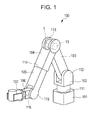
- FIG. 1 is a perspective view of a robot arm according to a first embodiment of the present invention.
- FIG. 2 is a cross-sectional view of a joint portion in FIG. 1 .
- FIG. 3 is a control block diagram of a rotary drive device according to the first embodiment of the present invention.
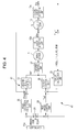
- FIG. 4 is a control block diagram of a rotary drive device according to a second embodiment of the present invention.
- FIG. 1 is a perspective view of a robot arm according to a first embodiment of the present invention.
- a robot arm 100 includes a base 101 fixed to an operation table, a swivel portion 102 that is supported by the base 101 in a manner capable of swiveling, and a first link 103 that is supported by the swivel portion 102 so as to be capable of swinging. Furthermore, the robot arm 100 includes a second link 104 that is supported by the first link 103 so as to be capable of swinging, and a third link 105 that is supported by the second link 104 so as to be capable of advancing and retracting.
- the robot arm 100 includes a tip link 106 that is supported by the third link 105 so as to be capable of swinging and a hand 107 provided on the tip link 106.
- These components are joined to one another by a first joint portion 111, a second joint portion 112, a third joint portion 113, a fourth joint portion 114, a fifth joint portion 115, and a sixth joint portion 116.
- Each of the joint portions 111 to 116 includes a servo motor 1 and a reduction gear 13 for reducing the rotational speed of the servo motor 1.
- the rotation shafts of the reduction gears 13 are connected to the respective components 102 to 106 to drive them.
- FIG. 2 is a cross-sectional view of the joint portion 113 in FIG. 1 .
- a rotary member of the servo motor 1 includes a rotation shaft 2 that serves as an output shaft, a flange 3, a rotor yoke 4, and a rotor magnet 5.
- a stator coil 7 is attached to a motor housing 6, and a bearing 8 supports the rotary member.
- a brake unit 9 is attached to an end of the rotation shaft 2 of the servo motor 1. Furthermore, a first encoder unit 10 that detects the rotation angle (angle position) of the rotation shaft 2 is attached to the end of the rotation shaft 2.
- the first encoder unit 10 is a reflection-type encoder unit including an encoder scale 11 that is fixed to the rotation shaft 2 and has a circumferentially provided slit and an encoder head 12 that is disposed opposite the encoder scale 11.
- the encoder head 12 is fixed to a frame 22, which is a fixed member on the first link 103 ( FIG. 1 ) side.
- the reduction gear 13 with a reduction ratio of N is attached to the other end of the rotation shaft 2.
- the reduction gear 13 is a harmonic drive (registered trademark).
- the reduction gear 13 includes a wave generator 14 joined to the rotation shaft 2 of the servo motor 1 and an annular rigid internal gear 15 fixed to the frame 22.
- the reduction gear 13 includes a flexible external gear 16 that is disposed between the wave generator 14 and the annular rigid internal gear 15 and rotates at a speed reduced from the rotational speed of the wave generator 14 by the reduction ratio N.
- the rotation shaft 20, serving as an output shaft, is fixed to this flexible external gear 16 so as to be coaxial with the rotation shaft 2.
- the rotation shaft 20 is joined to a frame 21 on the second link 104 ( FIG. 1 ) side, which is the object to be driven. Note that the servo motor 1 and the annular rigid internal gear 15 of the reduction gear 13 are also fixed to the frame 22.
- a second encoder unit 17 that detects the rotation angle (angle position) of the rotation shaft 20 is provided on the rotation shaft 20 of the reduction gear 13.
- the second encoder unit 17 is a reflection-type encoder unit including an encoder scale 18 that is fixed to the rotation shaft 2 and has a circumferentially provided slit and an encoder head 19 that is disposed opposite the encoder scale 18. Because the reflection-type encoder units 10 and 17 are smaller in thickness than a transmission type encoder, the space can be saved.
- FIG. 3 is a control block diagram of a rotary drive device 200 according to the first embodiment of the present invention.
- the rotary drive device 200 includes the above-described servo motor 1 and the reduction gear 13 with a reduction ratio of N, which is provided on the output side of the servo motor 1.
- the rotary drive device 200 includes the above-described first encoder unit 10 and a first angle-detecting unit 10A that detects the rotation angle of the rotation shaft 2 of the servo motor 1 and outputs a first rotation angle ⁇ m that can be obtained by dividing the detection result by the reduction ratio, N, of the reduction gear 13.
- the rotary drive device 200 includes the above-described second encoder unit 17 and a second angle-detecting unit 17A that detects the rotation angle of the rotation shaft 20 of the reduction gear 13 and outputs the detection result as a second rotation angle ⁇ g.
- the rotary drive device 200 includes a controller 23, an angle-control unit 24, a torque calculation unit 25, a torque control unit 26, and a current control unit 27.
- the controller 23 outputs an angle reference value ⁇ gref serving as a target rotation angle of the rotation shaft 20 of the reduction gear 13.
- the angle-control unit 24 calculates a torque reference value Tref serving as a target torque of the rotation shaft 20, such that the second rotation angle ⁇ g from the second angle-detecting unit 17A is equal to the angle reference value ⁇ gref.
- the angle-control unit 24 generates the torque reference value Tref of the rotation shaft 20 needed to bring the second rotation angle ⁇ g from the second angle-detecting unit 17A close to the angle reference value ⁇ gref according to the difference ⁇ gref - ⁇ g. That is, the angle-control unit 24 calculates the torque reference value Tref by PID-controlling the position feedback loop. This is because the equivalent transformation of the position and speed feedback loops into the position feedback is equivalent to the PID-controlled position feedback loop.
- the torque calculation unit 25 calculates the torque T acting on the rotation shaft 20 of the reduction gear 13, from an angle difference ⁇ diff between a first rotation angle ⁇ m, which is the output of the first angle-detecting unit 10A, and a second rotation angle ⁇ g, which is the output of the second angle-detecting unit 17A.
- the torque T is calculated by multiplying the angle difference ⁇ diff by a torsional stiffness K, which represents the stiffness of the reduction gear 13.
- the torque control unit 26 calculates the current reference value such that the torque T is equal to the torque reference value Tref. In other words, the torque control unit 26 generates a current reference value Iref needed to bring the torque T close to the torque reference value Tref according to the difference Tref - T.
- the current control unit 27 supplies a current i corresponding to the current reference value Iref to the servo motor 1.
- the angle difference ⁇ diff occurs between the first rotation angle ⁇ m, which is the output of the first angle-detecting unit 10A, and the second rotation angle ⁇ g, which is the output of the second angle-detecting unit 17A, due to the influence of the stiffness K of the reduction gear 13.
- This angle difference ⁇ diff represents a twisting angle by which the rotation shaft 20 of the reduction gear 13 is twisted in the rotation direction from the ideal position.
- the angle-control unit 24 recalculates the torque reference value Tref such that ⁇ gref is equal to ⁇ g.
- the torque control unit 26 recalculates the current reference value Iref such that the recalculated torque reference value Tref is equal to the torque T calculated from the angle difference ⁇ diff, and the current i is outputted to the servo motor 1 via the current control unit 27.
- the torque constant of the servo motor 1 is 0.04 Nm/A.
- the torque calculation unit 25 calculates the torque T from the angle difference ⁇ diff between the first rotation angle ⁇ m and the second rotation angle ⁇ g.
- the current reference value Iref is calculated from the difference between this calculated torque T and the torque reference value Tref generated by the torque control unit 26, and the current control unit 27 outputs the current i corresponding to the current reference value Iref to the servo motor 1.
- the disturbance torque is 0.5 Nm
- the exerted disturbance torque can be canceled and the position precision of the rotation shaft 20 of the reduction gear 13 can be maintained high.
- the rotation angle of the rotation shaft 20 of the reduction gear 13 is controlled according to the detection result of the second angle-detecting unit 17A. Accordingly, even if the rotation position of the rotation shaft 20 of the reduction gear 13 is shifted by a twisting angle (angle difference ⁇ diff) with respect to the rotation shaft 2 of the servo motor 1, due to insufficient strength or distortion of the reduction gear 13, it is possible to position the rotation shaft 20 of the reduction gear 13 with high precision. This increases the precision of movement, such as linear movement, of the robot arm 100.
- the vibration of the robot arm 100 can be suppressed without using a torque sensor.
- the joint portion 113 of the robot arm 100 has been described above, the joint portions 111 to 116 can also be controlled in the same way. In such cases too, it is possible to perform high-precision positioning of the robot arm 100 and to improve the precision of movement, such as linear movement. Furthermore, because the torque control is possible, the vibration of the robot arm 100 can be suppressed. Thus, it is possible to reduce the settling time and to reduce the waiting time before starting the movement of the robot arm 100.
- FIG. 4 is a control block diagram of the rotary drive device 200A according to the second embodiment of the present invention.
- the controller 23A not only outputs the angle reference value ⁇ gref, which is the target rotation angle of the rotation shaft 20 of the reduction gear 13, but also selects one of a first operation mode A and a second operation mode B.
- the selection of the operation mode by the controller 23A may be performed by a user operating an input device (not shown) or according to an operation program for moving the robot arm 100 ( FIG. 1 ).
- the rotary drive device 200A includes the servo motor 1, the reduction gear 13, the first angle-detecting unit 10A, the second angle-detecting unit 17A, the torque calculation unit 25, the torque control unit 26, and the current control unit 27, which have the same configurations as those in the first embodiment.
- the rotary drive device 200A includes the first angle-control unit 24 having the same configuration as the angle-control unit according to the first embodiment.
- the rotary drive device 200A includes a mode-changing switch 28, an angle-conversion calculation unit 29, and a second angle-control unit 30.
- the first angle-control unit 24, the torque calculation unit 25, and the torque control unit 26 constitute a first control loop 41
- the angle-conversion calculation unit 29 and the second angle-control unit 30 constitute a second control loop 42.
- the mode-changing switch 28 changes between the first control loop 41 and the second control loop 42 to which the angle reference value ⁇ gref is outputted, according to an operation mode signal from the controller 23.
- the operation mode signal indicates the selected operation mode.
- the mode-changing switch 28 is turned to the first control loop 41 side, allowing the angle reference value ⁇ gref to be outputted to the first control loop 41.
- the rotary drive device 200A moves in the same manner as the rotary drive device 200 according to the first embodiment.
- the mode-changing switch 28 is turned to the second control loop 42 side, allowing the angle reference value ⁇ gref to be outputted to the second control loop 42.
- the operation is different from that according to the first embodiment.
- the angle-conversion calculation unit 29 needs to calculate a reduced value because the angle reference value ⁇ gref is instructed on the basis of the resolution of the second angle-detecting unit 10A. Therefore, when the second operation mode B is selected, an output reference value ⁇ mref is generated by multiplying the angle reference value ⁇ gref by the reduced value obtained by dividing the resolution of the second angle-detecting unit 17A by the resolution of the first angle-detecting unit 10A.
- the reduced value is about 1.67.
- the second angle-control unit 30 calculates the current reference value such that the first rotation angle ⁇ m, which is the output of the first angle-detecting unit 17A, is equal to the output reference value ⁇ mref, on the basis of the output reference value ⁇ mref. In other words, the second angle-control unit 30 generates, by calculation, the current reference value Iref needed to bring the first rotation angle ⁇ m close to the output reference value ⁇ mref according to the difference between the output reference value ⁇ mref and the first rotation angle ⁇ m.
- the current control unit 27 inputs the current reference value Iref from the torque control unit 26 when the first operation mode A is selected, and inputs the current reference value Iref from the second angle-control unit 30 when the second operation mode B is selected. Then, the current control unit 27 supplies the current i corresponding to the current reference value Iref to the servo motor 1.
- the same control as the first embodiment is performed.
- it is possible to position the robot arm 100 with high precision and to suppress the vibration of the robot arm 100.
- the control loop is simple, and the control is performed only by detecting the angle of the rotation shaft 2 of the servo motor 1.
- a high-speed movement such as a high-speed operation or a quick start-up motion, becomes possible.
- changing the operation mode makes it possible to perform a high speed movement of the robot arm 100, to position the robot arm with high precision, and to suppress vibration.
- the present invention has been described according to the above-described embodiments, the present invention is not limited thereto. While a case in which the reduction gear 13 is a harmonic drive (registered trademark) has been described in the above-described embodiments, the same advantages can be obtained by using other reduction gears, such as a planetary gear.
- a harmonic drive registered trademark
- a first angle-detecting unit (10A) outputs a first rotation angle ( ⁇ m) according to the rotation angle of a rotation shaft of a servo motor (1).
- a second angle-detecting unit (17A) outputs a second rotation angle ( ⁇ g) according to a rotation angle of a rotation shaft of a reduction gear (13).
- a torque calculation unit (25) calculates the torque (T) acting on the rotation shaft of the reduction gear (13) according to the angle difference ( ⁇ diff) between the first rotation angle ( ⁇ m) and the second rotation angle ( ⁇ g).
- An angle-control unit (24) generates a torque reference value (Tref) according to the difference between the angle reference value ( ⁇ gref) and the second rotation angle ( ⁇ g).
- a torque control unit (26) generates a current reference value (Iref) according to the difference between the torque reference value (Tref) and the torque (T).
Landscapes
- Engineering & Computer Science (AREA)
- Robotics (AREA)
- Mechanical Engineering (AREA)
- Manipulator (AREA)
- Control Of Electric Motors In General (AREA)
- Retarders (AREA)
Applications Claiming Priority (1)
| Application Number | Priority Date | Filing Date | Title |
|---|---|---|---|
| JP2010037527A JP5645423B2 (ja) | 2010-02-23 | 2010-02-23 | 回転駆動装置及びロボットアーム |
Publications (3)
| Publication Number | Publication Date |
|---|---|
| EP2361736A2 true EP2361736A2 (fr) | 2011-08-31 |
| EP2361736A3 EP2361736A3 (fr) | 2017-11-29 |
| EP2361736B1 EP2361736B1 (fr) | 2020-01-08 |
Family
ID=44147593
Family Applications (1)
| Application Number | Title | Priority Date | Filing Date |
|---|---|---|---|
| EP11153652.0A Active EP2361736B1 (fr) | 2010-02-23 | 2011-02-08 | Dispositif d'entraînement rotatif |
Country Status (3)
| Country | Link |
|---|---|
| US (1) | US8482242B2 (fr) |
| EP (1) | EP2361736B1 (fr) |
| JP (1) | JP5645423B2 (fr) |
Cited By (12)
| Publication number | Priority date | Publication date | Assignee | Title |
|---|---|---|---|---|
| KR20130093545A (ko) * | 2012-02-14 | 2013-08-22 | 쿠카 로보테르 게엠베하 | 토크를 검출하기 위한 방법 및 산업용 로봇 |
| WO2013097976A3 (fr) * | 2011-12-27 | 2013-09-26 | Robert Bosch Gmbh | Procédé et dispositif de réglage de la position d'un élément de réglage d'un appareil de réglage |
| WO2015131904A1 (fr) * | 2014-03-04 | 2015-09-11 | Universal Robots A/S | Système de sécurité pour robot industriel |
| EP3023208A1 (fr) * | 2014-11-21 | 2016-05-25 | Canon Kabushiki Kaisha | Dispositif et procédé de commande pour dispositif d'entraînement de moteur et dispositif de commande pour moteur multiaxial |
| EP2965875A3 (fr) * | 2014-07-09 | 2016-06-29 | Canon Kabushiki Kaisha | Procédé de commande pour appareil robotisé, programme de commande, support d'enregistrement lisible par ordinateur et appareil robotisé |
| EP3109980A4 (fr) * | 2014-03-06 | 2018-04-18 | Sony Corporation | Actionneur et appareil de bras de robot |
| EP3264592A4 (fr) * | 2015-02-27 | 2018-08-22 | Sony Corporation | Actionneur et dispositif de bras de support médical |
| DE102018004357A1 (de) * | 2018-06-02 | 2019-12-05 | Franka Emika Gmbh | Antriebsvorrichtung für einen Manipulator |
| EP3623113A1 (fr) * | 2018-09-14 | 2020-03-18 | Universal Robots A/S | Obtention de la rigidité d'engrenage d'une roue d'articulation de robot d'un bras de robot |
| CN111673734A (zh) * | 2020-04-27 | 2020-09-18 | 驰驱电气(嘉兴)有限公司 | 一种机器人关节伺服系统振动抑制控制方法 |
| CN111673611A (zh) * | 2020-05-26 | 2020-09-18 | 华中科技大学 | 飞机复材构件机器人磨抛加工弹性变形及振动抑制方法 |
| WO2022146262A1 (fr) * | 2020-12-31 | 2022-07-07 | Ozyegin Universitesi | Mode de réalisation d'actionneur destiné à être utilisé dans des systèmes robotiques |
Families Citing this family (35)
| Publication number | Priority date | Publication date | Assignee | Title |
|---|---|---|---|---|
| JP5652042B2 (ja) * | 2010-08-06 | 2015-01-14 | セイコーエプソン株式会社 | ロボット装置、ロボット装置の制御方法およびプログラム |
| JP2013110874A (ja) * | 2011-11-22 | 2013-06-06 | Nidec-Shimpo Corp | 回転駆動装置及びロボット装置 |
| US9183346B2 (en) * | 2012-03-12 | 2015-11-10 | Empire Technology Development Llc | Robotic appendages |
| JP6083145B2 (ja) | 2012-07-31 | 2017-02-22 | セイコーエプソン株式会社 | ロボットの制御装置、およびロボット |
| JP5962340B2 (ja) * | 2012-08-31 | 2016-08-03 | セイコーエプソン株式会社 | ロボット |
| JP6111563B2 (ja) | 2012-08-31 | 2017-04-12 | セイコーエプソン株式会社 | ロボット |
| JP6053424B2 (ja) * | 2012-09-25 | 2016-12-27 | キヤノン株式会社 | ロボット装置、ロボット制御方法、プログラム及び記録媒体 |
| CN104968967B (zh) * | 2012-12-22 | 2017-12-22 | 株式会社沙夫特 | 旋转驱动装置 |
| JP6008121B2 (ja) * | 2013-01-28 | 2016-10-19 | セイコーエプソン株式会社 | ロボットおよびロボット制御装置 |
| WO2015023340A2 (fr) * | 2013-05-24 | 2015-02-19 | Carnegie Mellon University | Actionneurs élastiques en série pour robots et dispositifs robotiques |
| US9701000B2 (en) * | 2013-07-19 | 2017-07-11 | Panasonic Intellectual Property Management Co., Ltd. | Impact rotation tool and impact rotation tool attachment |
| US9505133B2 (en) | 2013-12-13 | 2016-11-29 | Canon Kabushiki Kaisha | Robot apparatus, robot controlling method, program and recording medium |
| US9718187B2 (en) * | 2014-06-11 | 2017-08-01 | Canon Kabushiki Kaisha | Robot controlling method, robot apparatus, program, recording medium, and method for manufacturing assembly component |
| JP6584102B2 (ja) * | 2015-03-13 | 2019-10-02 | キヤノン株式会社 | ロボット装置、ロボット制御方法、プログラム、記録媒体、及び物品の製造方法 |
| JP6487529B2 (ja) * | 2015-03-24 | 2019-03-20 | 住友重機械工業株式会社 | 旋回装置 |
| JP6684165B2 (ja) * | 2015-11-30 | 2020-04-22 | 日本電産シンポ株式会社 | 減速機システムの出力制御装置、減速機システムおよび減速機システムの出力制御方法 |
| WO2017094716A1 (fr) * | 2015-11-30 | 2017-06-08 | 日本電産シンポ株式会社 | Dispositif de commande de sortie pour système réducteur, système réducteur, et procédé de commande de sortie de système réducteur |
| JP6831208B2 (ja) * | 2015-12-25 | 2021-02-17 | 株式会社ダイヘン | ロボット制御装置 |
| US10980692B2 (en) | 2016-08-29 | 2021-04-20 | Mobius Imaging, Llc | Table system for medical imaging |
| US10369702B2 (en) * | 2016-10-17 | 2019-08-06 | Raytheon Company | Automated work piece moment of inertia (MOI) identification system and method for same |
| JP6952107B2 (ja) * | 2017-03-29 | 2021-10-20 | 住友重機械工業株式会社 | 親機械支援システム、親機械およびサーバ |
| JP2019077008A (ja) * | 2017-10-26 | 2019-05-23 | セイコーエプソン株式会社 | スカラロボット |
| KR102090446B1 (ko) * | 2018-11-12 | 2020-03-18 | (주)로보티즈 | 입력과 출력을 연결하는 탄성부재를 갖는 구동장치 |
| US11027435B2 (en) | 2018-12-04 | 2021-06-08 | Raytheon Company | Automated work piece testing system and method for same |
| US11198227B2 (en) | 2018-12-04 | 2021-12-14 | Raytheon Company | Adjustable ballast system and method for same |
| CN109551483B (zh) * | 2019-01-18 | 2024-09-17 | 王昊 | 一种具有力矩反馈的机械臂关节及其力矩计算方法 |
| JP7336215B2 (ja) | 2019-03-08 | 2023-08-31 | キヤノン株式会社 | ロボットシステム、制御方法、物品の製造方法、プログラム、及び記録媒体 |
| EP3976323B1 (fr) * | 2019-05-29 | 2024-10-09 | Universal Robots A/S | Contrôle d'un bras de robot polyvalent |
| JP7428527B2 (ja) * | 2020-02-04 | 2024-02-06 | ニデックインスツルメンツ株式会社 | モータ制御方法、モータ駆動装置、産業用ロボットの制御方法、及び産業用ロボット |
| CN111388093B (zh) * | 2020-02-19 | 2020-12-01 | 哈尔滨工业大学 | 一种基于协作关节电机的机器人及其控制方法 |
| GB2596813B (en) * | 2020-07-06 | 2024-09-18 | Cmr Surgical Ltd | Characterising the performance of a robotic joint |
| TWI794663B (zh) * | 2020-10-14 | 2023-03-01 | 達明機器人股份有限公司 | 機械手臂之編碼器模組 |
| JP7822703B2 (ja) * | 2021-03-26 | 2026-03-03 | 住友重機械工業株式会社 | 磁気変調ギヤ装置、駆動装置及びロボット |
| DE102024114371B3 (de) | 2024-05-22 | 2025-04-24 | Kuka Deutschland Gmbh | Verfahren zum Bestimmen eines durch ein Getriebe hindurchgeleiteten Drehmoments, Antriebssystem und Roboter mit einem solchen Antriebssystem |
| DE102024128767A1 (de) | 2024-10-07 | 2025-12-18 | Schaeffler Technologies AG & Co. KG | Verfahren zum Betrieb eines Spannungswellengetriebes, Antriebsmodul und Roboterarm |
Citations (3)
| Publication number | Priority date | Publication date | Assignee | Title |
|---|---|---|---|---|
| JPH05252779A (ja) | 1992-03-02 | 1993-09-28 | Matsushita Electric Ind Co Ltd | ロボットのサーボ制御装置 |
| JP2003018880A (ja) | 2001-07-02 | 2003-01-17 | Nidec-Shimpo Corp | 回転駆動装置及びそれに用いられる集積回路 |
| JP2006141101A (ja) | 2004-11-10 | 2006-06-01 | Sony Corp | アクチュエータ装置及び遊星減速機 |
Family Cites Families (27)
| Publication number | Priority date | Publication date | Assignee | Title |
|---|---|---|---|---|
| US5307447A (en) * | 1982-10-29 | 1994-04-26 | Kabushiki Kaisha Toshiba | Control system of multi-joint arm robot apparatus |
| DE3375107D1 (en) * | 1982-10-29 | 1988-02-11 | Toshiba Kk | Control system of multi-joint arm robot apparatus |
| JPS6144582A (ja) * | 1984-08-07 | 1986-03-04 | マツダ株式会社 | ナツトランナ−における塑性締め良否判定方法 |
| JP2681268B2 (ja) * | 1986-08-15 | 1997-11-26 | ファナック 株式会社 | 誘導電動機の運転モード切替装置 |
| US5062673A (en) * | 1988-12-28 | 1991-11-05 | Kabushiki Kaisha Toyota Chuo Kenkyusho | Articulated hand |
| US5243526A (en) * | 1990-05-18 | 1993-09-07 | Mitsubishi Jidosha Kogyo Kabushiki Kaisha | Output control apparatus for vehicle |
| US5355064A (en) * | 1992-03-04 | 1994-10-11 | Honda Giken Kogyo Kabushiki Kaisha | Control system for legged mobile robot |
| JPH05292773A (ja) * | 1992-04-06 | 1993-11-05 | Komatsu Ltd | ロボットの振動低減制御装置 |
| US5404086A (en) * | 1992-07-20 | 1995-04-04 | Honda Giken Kogyo Kabushiki Kaisha | System for controlling locomotion of legged mobile robot and correcting inclinometer's output thereof |
| JPH08278821A (ja) * | 1995-04-06 | 1996-10-22 | Kobe Steel Ltd | サーボ制御系の制振方法 |
| US5994864A (en) * | 1995-09-11 | 1999-11-30 | Kabushiki Kaisha Yaskawa Denki | Robot controller |
| JP3239789B2 (ja) * | 1997-02-21 | 2001-12-17 | 松下電器産業株式会社 | 制御装置および制御方法 |
| JP4483060B2 (ja) * | 2000-09-22 | 2010-06-16 | ソニー株式会社 | アクチュエータ装置 |
| JP2003160053A (ja) * | 2001-11-28 | 2003-06-03 | Toyoda Mach Works Ltd | 電気式動力舵取装置 |
| JP3758563B2 (ja) * | 2001-12-04 | 2006-03-22 | 豊田工機株式会社 | 位置検出器の補正方法、及び、電気式動力舵取装置 |
| JP4007200B2 (ja) * | 2003-01-20 | 2007-11-14 | 株式会社ジェイテクト | 電動パワーステアリング装置 |
| JP2004291877A (ja) * | 2003-03-27 | 2004-10-21 | Toyoda Mach Works Ltd | 車両用操舵装置 |
| JP3891288B2 (ja) * | 2003-03-28 | 2007-03-14 | 株式会社ジェイテクト | 電気式動力舵取装置 |
| WO2005009692A1 (fr) * | 2003-07-29 | 2005-02-03 | Matsushita Electric Industrial Co., Ltd. | Procede de commande du bras d'un robot et dispositif de commande associe |
| JP4405788B2 (ja) * | 2003-11-18 | 2010-01-27 | 日本精工株式会社 | 電動パワーステアリング装置の制御装置 |
| JP3883544B2 (ja) * | 2004-02-27 | 2007-02-21 | 株式会社東芝 | ロボット制御装置およびロボットの制御方法 |
| JP4581543B2 (ja) * | 2004-08-02 | 2010-11-17 | 株式会社安川電機 | 減速機一体型アクチュエータおよびこれを備えたアクチュエータシステム |
| JP4577107B2 (ja) * | 2005-06-17 | 2010-11-10 | 三菱電機株式会社 | 機械位置制御装置 |
| US7325646B2 (en) * | 2005-07-15 | 2008-02-05 | Jtekt Corporation | Electric power steering apparatus |
| DE602007004029D1 (de) * | 2006-07-14 | 2010-02-11 | Nsk Ltd | Steuervorrichtung für eine Servolenkvorrichtung |
| JP4715863B2 (ja) * | 2008-05-01 | 2011-07-06 | ソニー株式会社 | アクチュエータ制御装置及びアクチュエータ制御方法、アクチュエータ、ロボット装置、並びにコンピュータ・プログラム |
| JP5821210B2 (ja) * | 2011-02-22 | 2015-11-24 | セイコーエプソン株式会社 | 水平多関節ロボット及び水平多関節ロボットの制御方法 |
-
2010
- 2010-02-23 JP JP2010037527A patent/JP5645423B2/ja not_active Expired - Fee Related
-
2011
- 2011-02-08 EP EP11153652.0A patent/EP2361736B1/fr active Active
- 2011-02-22 US US13/032,497 patent/US8482242B2/en not_active Expired - Fee Related
Patent Citations (3)
| Publication number | Priority date | Publication date | Assignee | Title |
|---|---|---|---|---|
| JPH05252779A (ja) | 1992-03-02 | 1993-09-28 | Matsushita Electric Ind Co Ltd | ロボットのサーボ制御装置 |
| JP2003018880A (ja) | 2001-07-02 | 2003-01-17 | Nidec-Shimpo Corp | 回転駆動装置及びそれに用いられる集積回路 |
| JP2006141101A (ja) | 2004-11-10 | 2006-06-01 | Sony Corp | アクチュエータ装置及び遊星減速機 |
Cited By (23)
| Publication number | Priority date | Publication date | Assignee | Title |
|---|---|---|---|---|
| WO2013097976A3 (fr) * | 2011-12-27 | 2013-09-26 | Robert Bosch Gmbh | Procédé et dispositif de réglage de la position d'un élément de réglage d'un appareil de réglage |
| EP2628575A3 (fr) * | 2012-02-14 | 2017-12-20 | KUKA Roboter GmbH | Procédé destiné à déterminer un couple et robot industriel |
| KR20130093545A (ko) * | 2012-02-14 | 2013-08-22 | 쿠카 로보테르 게엠베하 | 토크를 검출하기 위한 방법 및 산업용 로봇 |
| CN106061688B (zh) * | 2014-03-04 | 2020-03-17 | 优傲机器人公司 | 用于工业机器人的安全系统 |
| US10399232B2 (en) | 2014-03-04 | 2019-09-03 | Universal Robots A/S | Safety system for industrial robot |
| CN106061688A (zh) * | 2014-03-04 | 2016-10-26 | 优傲机器人公司 | 用于工业机器人的安全系统 |
| WO2015131904A1 (fr) * | 2014-03-04 | 2015-09-11 | Universal Robots A/S | Système de sécurité pour robot industriel |
| EP3109980A4 (fr) * | 2014-03-06 | 2018-04-18 | Sony Corporation | Actionneur et appareil de bras de robot |
| US10505428B2 (en) | 2014-03-06 | 2019-12-10 | Sony Corporation | Actuator and robot arm apparatus |
| US9966816B2 (en) | 2014-03-06 | 2018-05-08 | Sony Corporation | Actuator and robot arm apparatus |
| EP2965875A3 (fr) * | 2014-07-09 | 2016-06-29 | Canon Kabushiki Kaisha | Procédé de commande pour appareil robotisé, programme de commande, support d'enregistrement lisible par ordinateur et appareil robotisé |
| US9815202B2 (en) | 2014-07-09 | 2017-11-14 | Canon Kabushiki Kaisha | Control method for robot apparatus, computer readable recording medium, and robot apparatus |
| US10029366B2 (en) | 2014-11-21 | 2018-07-24 | Canon Kabushiki Kaisha | Control device for motor drive device, control device for multi-axial motor, and control method for motor drive device |
| EP3023208A1 (fr) * | 2014-11-21 | 2016-05-25 | Canon Kabushiki Kaisha | Dispositif et procédé de commande pour dispositif d'entraînement de moteur et dispositif de commande pour moteur multiaxial |
| EP3264592A4 (fr) * | 2015-02-27 | 2018-08-22 | Sony Corporation | Actionneur et dispositif de bras de support médical |
| DE102018004357A1 (de) * | 2018-06-02 | 2019-12-05 | Franka Emika Gmbh | Antriebsvorrichtung für einen Manipulator |
| EP3623113A1 (fr) * | 2018-09-14 | 2020-03-18 | Universal Robots A/S | Obtention de la rigidité d'engrenage d'une roue d'articulation de robot d'un bras de robot |
| WO2020053195A1 (fr) * | 2018-09-14 | 2020-03-19 | Universal Robots A/S | Obtention de la rigidité d'engrenage d'un engrenage d'articulation de robot d'un bras de robot |
| CN111673734A (zh) * | 2020-04-27 | 2020-09-18 | 驰驱电气(嘉兴)有限公司 | 一种机器人关节伺服系统振动抑制控制方法 |
| CN111673734B (zh) * | 2020-04-27 | 2021-07-16 | 驰驱电气(嘉兴)有限公司 | 一种机器人关节伺服系统振动抑制控制方法 |
| CN111673611A (zh) * | 2020-05-26 | 2020-09-18 | 华中科技大学 | 飞机复材构件机器人磨抛加工弹性变形及振动抑制方法 |
| WO2022146262A1 (fr) * | 2020-12-31 | 2022-07-07 | Ozyegin Universitesi | Mode de réalisation d'actionneur destiné à être utilisé dans des systèmes robotiques |
| US12017353B2 (en) | 2020-12-31 | 2024-06-25 | Ozyegin Universitesi | Actuator embodiment for use in robot systems |
Also Published As
| Publication number | Publication date |
|---|---|
| EP2361736B1 (fr) | 2020-01-08 |
| US8482242B2 (en) | 2013-07-09 |
| EP2361736A3 (fr) | 2017-11-29 |
| US20110204838A1 (en) | 2011-08-25 |
| JP2011176913A (ja) | 2011-09-08 |
| JP5645423B2 (ja) | 2014-12-24 |
Similar Documents
| Publication | Publication Date | Title |
|---|---|---|
| US8482242B2 (en) | Rotary drive device | |
| EP2492057B1 (fr) | Robot, système de robot et machine électrique rotative | |
| JP5400473B2 (ja) | ロボット装置 | |
| JP7170389B2 (ja) | ギヤモータ | |
| JP4339275B2 (ja) | インパクト式のネジ締め装置の制御方法および装置 | |
| JP5411978B2 (ja) | ボールネジの伸縮量を補正する機能を備えたサーボ制御装置 | |
| WO2019031219A1 (fr) | Procédé de transmission d'informations dans un dispositif de commande et procédé de détection d'une anomalie dans un codeur | |
| JP2018196266A (ja) | モータ制御システム、モータ制御システムの制御方法、及びロボットシステム | |
| US10295419B2 (en) | Actuator | |
| US11073497B2 (en) | Machine tool and vibration diagnosis support method | |
| KR101015483B1 (ko) | 모터 제어 장치 및 모터 제어 방법 | |
| JP4361285B2 (ja) | 数値制御装置 | |
| JP6271903B2 (ja) | サーボ装置、及びサーボ装置の制御方法 | |
| JP2009072033A (ja) | 位置検出器の初期位置調整方法及びこの方法を用いた電動機駆動装置 | |
| JP4838817B2 (ja) | ロストモーション解消制御装置 | |
| JP2008020465A (ja) | 直接駆動モータを用いた回転粘度計 | |
| JP4827678B2 (ja) | アクチュエータの位置変動抑制方法 | |
| JP6087537B2 (ja) | 制御装置およびステッピングモータの制御方法 | |
| JP4409115B2 (ja) | 位置制御装置および位置制御方法 | |
| JP2014096922A (ja) | ステッピングモーターの制御方法、制御装置およびロボット | |
| JP4668776B2 (ja) | モータのトルクリプル測定方法、測定装置、トルクリプル抑制方法およびその抑制方法を適用したモータ駆動装置 | |
| JP2021023085A (ja) | モータ駆動制御装置、モータユニット、及びアクチュエータ | |
| US8480318B2 (en) | Driving force transmitting device and camera platform device using the same | |
| JP2021058953A (ja) | ロボット制御装置 | |
| JP7604978B2 (ja) | アクチュエータ |
Legal Events
| Date | Code | Title | Description |
|---|---|---|---|
| PUAI | Public reference made under article 153(3) epc to a published international application that has entered the european phase |
Free format text: ORIGINAL CODE: 0009012 |
|
| AK | Designated contracting states |
Kind code of ref document: A2 Designated state(s): AL AT BE BG CH CY CZ DE DK EE ES FI FR GB GR HR HU IE IS IT LI LT LU LV MC MK MT NL NO PL PT RO RS SE SI SK SM TR |
|
| AX | Request for extension of the european patent |
Extension state: BA ME |
|
| PUAL | Search report despatched |
Free format text: ORIGINAL CODE: 0009013 |
|
| AK | Designated contracting states |
Kind code of ref document: A3 Designated state(s): AL AT BE BG CH CY CZ DE DK EE ES FI FR GB GR HR HU IE IS IT LI LT LU LV MC MK MT NL NO PL PT RO RS SE SI SK SM TR |
|
| AX | Request for extension of the european patent |
Extension state: BA ME |
|
| RIC1 | Information provided on ipc code assigned before grant |
Ipc: B25J 9/16 20060101AFI20171020BHEP |
|
| STAA | Information on the status of an ep patent application or granted ep patent |
Free format text: STATUS: REQUEST FOR EXAMINATION WAS MADE |
|
| 17P | Request for examination filed |
Effective date: 20180529 |
|
| RBV | Designated contracting states (corrected) |
Designated state(s): AL AT BE BG CH CY CZ DE DK EE ES FI FR GB GR HR HU IE IS IT LI LT LU LV MC MK MT NL NO PL PT RO RS SE SI SK SM TR |
|
| GRAP | Despatch of communication of intention to grant a patent |
Free format text: ORIGINAL CODE: EPIDOSNIGR1 |
|
| STAA | Information on the status of an ep patent application or granted ep patent |
Free format text: STATUS: GRANT OF PATENT IS INTENDED |
|
| INTG | Intention to grant announced |
Effective date: 20190725 |
|
| GRAS | Grant fee paid |
Free format text: ORIGINAL CODE: EPIDOSNIGR3 |
|
| GRAA | (expected) grant |
Free format text: ORIGINAL CODE: 0009210 |
|
| STAA | Information on the status of an ep patent application or granted ep patent |
Free format text: STATUS: THE PATENT HAS BEEN GRANTED |
|
| AK | Designated contracting states |
Kind code of ref document: B1 Designated state(s): AL AT BE BG CH CY CZ DE DK EE ES FI FR GB GR HR HU IE IS IT LI LT LU LV MC MK MT NL NO PL PT RO RS SE SI SK SM TR |
|
| REG | Reference to a national code |
Ref country code: GB Ref legal event code: FG4D |
|
| REG | Reference to a national code |
Ref country code: CH Ref legal event code: EP |
|
| REG | Reference to a national code |
Ref country code: IE Ref legal event code: FG4D |
|
| REG | Reference to a national code |
Ref country code: DE Ref legal event code: R096 Ref document number: 602011064442 Country of ref document: DE |
|
| REG | Reference to a national code |
Ref country code: AT Ref legal event code: REF Ref document number: 1222120 Country of ref document: AT Kind code of ref document: T Effective date: 20200215 |
|
| REG | Reference to a national code |
Ref country code: NL Ref legal event code: MP Effective date: 20200108 |
|
| REG | Reference to a national code |
Ref country code: LT Ref legal event code: MG4D |
|
| PG25 | Lapsed in a contracting state [announced via postgrant information from national office to epo] |
Ref country code: NO Free format text: LAPSE BECAUSE OF FAILURE TO SUBMIT A TRANSLATION OF THE DESCRIPTION OR TO PAY THE FEE WITHIN THE PRESCRIBED TIME-LIMIT Effective date: 20200408 Ref country code: FI Free format text: LAPSE BECAUSE OF FAILURE TO SUBMIT A TRANSLATION OF THE DESCRIPTION OR TO PAY THE FEE WITHIN THE PRESCRIBED TIME-LIMIT Effective date: 20200108 Ref country code: RS Free format text: LAPSE BECAUSE OF FAILURE TO SUBMIT A TRANSLATION OF THE DESCRIPTION OR TO PAY THE FEE WITHIN THE PRESCRIBED TIME-LIMIT Effective date: 20200108 Ref country code: PT Free format text: LAPSE BECAUSE OF FAILURE TO SUBMIT A TRANSLATION OF THE DESCRIPTION OR TO PAY THE FEE WITHIN THE PRESCRIBED TIME-LIMIT Effective date: 20200531 Ref country code: LT Free format text: LAPSE BECAUSE OF FAILURE TO SUBMIT A TRANSLATION OF THE DESCRIPTION OR TO PAY THE FEE WITHIN THE PRESCRIBED TIME-LIMIT Effective date: 20200108 Ref country code: NL Free format text: LAPSE BECAUSE OF FAILURE TO SUBMIT A TRANSLATION OF THE DESCRIPTION OR TO PAY THE FEE WITHIN THE PRESCRIBED TIME-LIMIT Effective date: 20200108 |
|
| PG25 | Lapsed in a contracting state [announced via postgrant information from national office to epo] |
Ref country code: BG Free format text: LAPSE BECAUSE OF FAILURE TO SUBMIT A TRANSLATION OF THE DESCRIPTION OR TO PAY THE FEE WITHIN THE PRESCRIBED TIME-LIMIT Effective date: 20200408 Ref country code: GR Free format text: LAPSE BECAUSE OF FAILURE TO SUBMIT A TRANSLATION OF THE DESCRIPTION OR TO PAY THE FEE WITHIN THE PRESCRIBED TIME-LIMIT Effective date: 20200409 Ref country code: IS Free format text: LAPSE BECAUSE OF FAILURE TO SUBMIT A TRANSLATION OF THE DESCRIPTION OR TO PAY THE FEE WITHIN THE PRESCRIBED TIME-LIMIT Effective date: 20200508 Ref country code: LV Free format text: LAPSE BECAUSE OF FAILURE TO SUBMIT A TRANSLATION OF THE DESCRIPTION OR TO PAY THE FEE WITHIN THE PRESCRIBED TIME-LIMIT Effective date: 20200108 Ref country code: SE Free format text: LAPSE BECAUSE OF FAILURE TO SUBMIT A TRANSLATION OF THE DESCRIPTION OR TO PAY THE FEE WITHIN THE PRESCRIBED TIME-LIMIT Effective date: 20200108 Ref country code: HR Free format text: LAPSE BECAUSE OF FAILURE TO SUBMIT A TRANSLATION OF THE DESCRIPTION OR TO PAY THE FEE WITHIN THE PRESCRIBED TIME-LIMIT Effective date: 20200108 |
|
| REG | Reference to a national code |
Ref country code: CH Ref legal event code: PL |
|
| REG | Reference to a national code |
Ref country code: DE Ref legal event code: R097 Ref document number: 602011064442 Country of ref document: DE |
|
| REG | Reference to a national code |
Ref country code: BE Ref legal event code: MM Effective date: 20200229 |
|
| PG25 | Lapsed in a contracting state [announced via postgrant information from national office to epo] |
Ref country code: ES Free format text: LAPSE BECAUSE OF FAILURE TO SUBMIT A TRANSLATION OF THE DESCRIPTION OR TO PAY THE FEE WITHIN THE PRESCRIBED TIME-LIMIT Effective date: 20200108 Ref country code: LU Free format text: LAPSE BECAUSE OF NON-PAYMENT OF DUE FEES Effective date: 20200208 Ref country code: MC Free format text: LAPSE BECAUSE OF FAILURE TO SUBMIT A TRANSLATION OF THE DESCRIPTION OR TO PAY THE FEE WITHIN THE PRESCRIBED TIME-LIMIT Effective date: 20200108 Ref country code: SK Free format text: LAPSE BECAUSE OF FAILURE TO SUBMIT A TRANSLATION OF THE DESCRIPTION OR TO PAY THE FEE WITHIN THE PRESCRIBED TIME-LIMIT Effective date: 20200108 Ref country code: RO Free format text: LAPSE BECAUSE OF FAILURE TO SUBMIT A TRANSLATION OF THE DESCRIPTION OR TO PAY THE FEE WITHIN THE PRESCRIBED TIME-LIMIT Effective date: 20200108 Ref country code: CZ Free format text: LAPSE BECAUSE OF FAILURE TO SUBMIT A TRANSLATION OF THE DESCRIPTION OR TO PAY THE FEE WITHIN THE PRESCRIBED TIME-LIMIT Effective date: 20200108 Ref country code: DK Free format text: LAPSE BECAUSE OF FAILURE TO SUBMIT A TRANSLATION OF THE DESCRIPTION OR TO PAY THE FEE WITHIN THE PRESCRIBED TIME-LIMIT Effective date: 20200108 Ref country code: SM Free format text: LAPSE BECAUSE OF FAILURE TO SUBMIT A TRANSLATION OF THE DESCRIPTION OR TO PAY THE FEE WITHIN THE PRESCRIBED TIME-LIMIT Effective date: 20200108 Ref country code: EE Free format text: LAPSE BECAUSE OF FAILURE TO SUBMIT A TRANSLATION OF THE DESCRIPTION OR TO PAY THE FEE WITHIN THE PRESCRIBED TIME-LIMIT Effective date: 20200108 |
|
| PLBE | No opposition filed within time limit |
Free format text: ORIGINAL CODE: 0009261 |
|
| STAA | Information on the status of an ep patent application or granted ep patent |
Free format text: STATUS: NO OPPOSITION FILED WITHIN TIME LIMIT |
|
| REG | Reference to a national code |
Ref country code: AT Ref legal event code: MK05 Ref document number: 1222120 Country of ref document: AT Kind code of ref document: T Effective date: 20200108 |
|
| PG25 | Lapsed in a contracting state [announced via postgrant information from national office to epo] |
Ref country code: CH Free format text: LAPSE BECAUSE OF NON-PAYMENT OF DUE FEES Effective date: 20200229 Ref country code: LI Free format text: LAPSE BECAUSE OF NON-PAYMENT OF DUE FEES Effective date: 20200229 |
|
| 26N | No opposition filed |
Effective date: 20201009 |
|
| PG25 | Lapsed in a contracting state [announced via postgrant information from national office to epo] |
Ref country code: IT Free format text: LAPSE BECAUSE OF FAILURE TO SUBMIT A TRANSLATION OF THE DESCRIPTION OR TO PAY THE FEE WITHIN THE PRESCRIBED TIME-LIMIT Effective date: 20200108 Ref country code: IE Free format text: LAPSE BECAUSE OF NON-PAYMENT OF DUE FEES Effective date: 20200208 Ref country code: FR Free format text: LAPSE BECAUSE OF NON-PAYMENT OF DUE FEES Effective date: 20200308 Ref country code: AT Free format text: LAPSE BECAUSE OF FAILURE TO SUBMIT A TRANSLATION OF THE DESCRIPTION OR TO PAY THE FEE WITHIN THE PRESCRIBED TIME-LIMIT Effective date: 20200108 |
|
| PG25 | Lapsed in a contracting state [announced via postgrant information from national office to epo] |
Ref country code: PL Free format text: LAPSE BECAUSE OF FAILURE TO SUBMIT A TRANSLATION OF THE DESCRIPTION OR TO PAY THE FEE WITHIN THE PRESCRIBED TIME-LIMIT Effective date: 20200108 Ref country code: BE Free format text: LAPSE BECAUSE OF NON-PAYMENT OF DUE FEES Effective date: 20200229 Ref country code: SI Free format text: LAPSE BECAUSE OF FAILURE TO SUBMIT A TRANSLATION OF THE DESCRIPTION OR TO PAY THE FEE WITHIN THE PRESCRIBED TIME-LIMIT Effective date: 20200108 |
|
| GBPC | Gb: european patent ceased through non-payment of renewal fee |
Effective date: 20200408 |
|
| PG25 | Lapsed in a contracting state [announced via postgrant information from national office to epo] |
Ref country code: GB Free format text: LAPSE BECAUSE OF NON-PAYMENT OF DUE FEES Effective date: 20200408 |
|
| PG25 | Lapsed in a contracting state [announced via postgrant information from national office to epo] |
Ref country code: TR Free format text: LAPSE BECAUSE OF FAILURE TO SUBMIT A TRANSLATION OF THE DESCRIPTION OR TO PAY THE FEE WITHIN THE PRESCRIBED TIME-LIMIT Effective date: 20200108 Ref country code: MT Free format text: LAPSE BECAUSE OF FAILURE TO SUBMIT A TRANSLATION OF THE DESCRIPTION OR TO PAY THE FEE WITHIN THE PRESCRIBED TIME-LIMIT Effective date: 20200108 Ref country code: CY Free format text: LAPSE BECAUSE OF FAILURE TO SUBMIT A TRANSLATION OF THE DESCRIPTION OR TO PAY THE FEE WITHIN THE PRESCRIBED TIME-LIMIT Effective date: 20200108 |
|
| PG25 | Lapsed in a contracting state [announced via postgrant information from national office to epo] |
Ref country code: MK Free format text: LAPSE BECAUSE OF FAILURE TO SUBMIT A TRANSLATION OF THE DESCRIPTION OR TO PAY THE FEE WITHIN THE PRESCRIBED TIME-LIMIT Effective date: 20200108 Ref country code: AL Free format text: LAPSE BECAUSE OF FAILURE TO SUBMIT A TRANSLATION OF THE DESCRIPTION OR TO PAY THE FEE WITHIN THE PRESCRIBED TIME-LIMIT Effective date: 20200108 |
|
| PGFP | Annual fee paid to national office [announced via postgrant information from national office to epo] |
Ref country code: DE Payment date: 20240123 Year of fee payment: 14 |
|
| REG | Reference to a national code |
Ref country code: DE Ref legal event code: R119 Ref document number: 602011064442 Country of ref document: DE |
|
| PG25 | Lapsed in a contracting state [announced via postgrant information from national office to epo] |
Ref country code: DE Free format text: LAPSE BECAUSE OF NON-PAYMENT OF DUE FEES Effective date: 20250902 |