EP2362034A2 - Agencement de fixation d'au moins une plaque sur une paroi de bâtiment - Google Patents
Agencement de fixation d'au moins une plaque sur une paroi de bâtiment Download PDFInfo
- Publication number
- EP2362034A2 EP2362034A2 EP11001396A EP11001396A EP2362034A2 EP 2362034 A2 EP2362034 A2 EP 2362034A2 EP 11001396 A EP11001396 A EP 11001396A EP 11001396 A EP11001396 A EP 11001396A EP 2362034 A2 EP2362034 A2 EP 2362034A2
- Authority
- EP
- European Patent Office
- Prior art keywords
- plate
- stop
- building
- building wall
- fastening device
- Prior art date
- Legal status (The legal status is an assumption and is not a legal conclusion. Google has not performed a legal analysis and makes no representation as to the accuracy of the status listed.)
- Withdrawn
Links
- 238000010276 construction Methods 0.000 claims abstract description 7
- XLYOFNOQVPJJNP-UHFFFAOYSA-N water Substances O XLYOFNOQVPJJNP-UHFFFAOYSA-N 0.000 claims description 4
- 230000005611 electricity Effects 0.000 claims description 2
- 239000002131 composite material Substances 0.000 description 3
- 239000011521 glass Substances 0.000 description 3
- 239000002023 wood Substances 0.000 description 3
- 230000006978 adaptation Effects 0.000 description 2
- 239000004568 cement Substances 0.000 description 2
- 239000002184 metal Substances 0.000 description 2
- 229910052751 metal Inorganic materials 0.000 description 2
- 239000004575 stone Substances 0.000 description 2
- 229910000746 Structural steel Inorganic materials 0.000 description 1
- 239000011449 brick Substances 0.000 description 1
- 238000005253 cladding Methods 0.000 description 1
- 239000004927 clay Substances 0.000 description 1
- 239000004567 concrete Substances 0.000 description 1
- 230000000694 effects Effects 0.000 description 1
- 239000000463 material Substances 0.000 description 1
- -1 plasterboard Substances 0.000 description 1
- 239000000725 suspension Substances 0.000 description 1
Images


Classifications
-
- E—FIXED CONSTRUCTIONS
- E04—BUILDING
- E04F—FINISHING WORK ON BUILDINGS, e.g. STAIRS, FLOORS
- E04F13/00—Coverings or linings, e.g. for walls or ceilings
- E04F13/07—Coverings or linings, e.g. for walls or ceilings composed of covering or lining elements; Sub-structures therefor; Fastening means therefor
- E04F13/08—Coverings or linings, e.g. for walls or ceilings composed of covering or lining elements; Sub-structures therefor; Fastening means therefor composed of a plurality of similar covering or lining elements
- E04F13/0801—Separate fastening elements
- E04F13/0803—Separate fastening elements with load-supporting elongated furring elements between wall and covering elements
- E04F13/081—Separate fastening elements with load-supporting elongated furring elements between wall and covering elements with additional fastening elements between furring elements and covering elements
- E04F13/0821—Separate fastening elements with load-supporting elongated furring elements between wall and covering elements with additional fastening elements between furring elements and covering elements the additional fastening elements located in-between two adjacent covering elements
-
- F—MECHANICAL ENGINEERING; LIGHTING; HEATING; WEAPONS; BLASTING
- F24—HEATING; RANGES; VENTILATING
- F24S—SOLAR HEAT COLLECTORS; SOLAR HEAT SYSTEMS
- F24S20/00—Solar heat collectors specially adapted for particular uses or environments
- F24S20/60—Solar heat collectors integrated in fixed constructions, e.g. in buildings
- F24S20/66—Solar heat collectors integrated in fixed constructions, e.g. in buildings in the form of facade constructions, e.g. wall constructions
-
- F—MECHANICAL ENGINEERING; LIGHTING; HEATING; WEAPONS; BLASTING
- F24—HEATING; RANGES; VENTILATING
- F24S—SOLAR HEAT COLLECTORS; SOLAR HEAT SYSTEMS
- F24S25/00—Arrangement of stationary mountings or supports for solar heat collector modules
- F24S25/30—Arrangement of stationary mountings or supports for solar heat collector modules using elongate rigid mounting elements extending substantially along the supporting surface, e.g. for covering buildings with solar heat collectors
- F24S25/33—Arrangement of stationary mountings or supports for solar heat collector modules using elongate rigid mounting elements extending substantially along the supporting surface, e.g. for covering buildings with solar heat collectors forming substantially planar assemblies, e.g. of coplanar or stacked profiles
-
- F—MECHANICAL ENGINEERING; LIGHTING; HEATING; WEAPONS; BLASTING
- F24—HEATING; RANGES; VENTILATING
- F24S—SOLAR HEAT COLLECTORS; SOLAR HEAT SYSTEMS
- F24S25/00—Arrangement of stationary mountings or supports for solar heat collector modules
- F24S25/60—Fixation means, e.g. fasteners, specially adapted for supporting solar heat collector modules
- F24S25/63—Fixation means, e.g. fasteners, specially adapted for supporting solar heat collector modules for fixing modules or their peripheral frames to supporting elements
- F24S25/632—Side connectors; Base connectors
-
- F—MECHANICAL ENGINEERING; LIGHTING; HEATING; WEAPONS; BLASTING
- F24—HEATING; RANGES; VENTILATING
- F24S—SOLAR HEAT COLLECTORS; SOLAR HEAT SYSTEMS
- F24S25/00—Arrangement of stationary mountings or supports for solar heat collector modules
- F24S25/70—Arrangement of stationary mountings or supports for solar heat collector modules with means for adjusting the final position or orientation of supporting elements in relation to each other or to a mounting surface; with means for compensating mounting tolerances
-
- H—ELECTRICITY
- H02—GENERATION; CONVERSION OR DISTRIBUTION OF ELECTRIC POWER
- H02S—GENERATION OF ELECTRIC POWER BY CONVERSION OF INFRARED RADIATION, VISIBLE LIGHT OR ULTRAVIOLET LIGHT, e.g. USING PHOTOVOLTAIC [PV] MODULES
- H02S20/00—Supporting structures for PV modules
- H02S20/20—Supporting structures directly fixed to an immovable object
- H02S20/22—Supporting structures directly fixed to an immovable object specially adapted for buildings
- H02S20/26—Building materials integrated with PV modules, e.g. façade elements
-
- Y—GENERAL TAGGING OF NEW TECHNOLOGICAL DEVELOPMENTS; GENERAL TAGGING OF CROSS-SECTIONAL TECHNOLOGIES SPANNING OVER SEVERAL SECTIONS OF THE IPC; TECHNICAL SUBJECTS COVERED BY FORMER USPC CROSS-REFERENCE ART COLLECTIONS [XRACs] AND DIGESTS
- Y02—TECHNOLOGIES OR APPLICATIONS FOR MITIGATION OR ADAPTATION AGAINST CLIMATE CHANGE
- Y02B—CLIMATE CHANGE MITIGATION TECHNOLOGIES RELATED TO BUILDINGS, e.g. HOUSING, HOUSE APPLIANCES OR RELATED END-USER APPLICATIONS
- Y02B10/00—Integration of renewable energy sources in buildings
- Y02B10/10—Photovoltaic [PV]
-
- Y—GENERAL TAGGING OF NEW TECHNOLOGICAL DEVELOPMENTS; GENERAL TAGGING OF CROSS-SECTIONAL TECHNOLOGIES SPANNING OVER SEVERAL SECTIONS OF THE IPC; TECHNICAL SUBJECTS COVERED BY FORMER USPC CROSS-REFERENCE ART COLLECTIONS [XRACs] AND DIGESTS
- Y02—TECHNOLOGIES OR APPLICATIONS FOR MITIGATION OR ADAPTATION AGAINST CLIMATE CHANGE
- Y02B—CLIMATE CHANGE MITIGATION TECHNOLOGIES RELATED TO BUILDINGS, e.g. HOUSING, HOUSE APPLIANCES OR RELATED END-USER APPLICATIONS
- Y02B10/00—Integration of renewable energy sources in buildings
- Y02B10/20—Solar thermal
-
- Y—GENERAL TAGGING OF NEW TECHNOLOGICAL DEVELOPMENTS; GENERAL TAGGING OF CROSS-SECTIONAL TECHNOLOGIES SPANNING OVER SEVERAL SECTIONS OF THE IPC; TECHNICAL SUBJECTS COVERED BY FORMER USPC CROSS-REFERENCE ART COLLECTIONS [XRACs] AND DIGESTS
- Y02—TECHNOLOGIES OR APPLICATIONS FOR MITIGATION OR ADAPTATION AGAINST CLIMATE CHANGE
- Y02E—REDUCTION OF GREENHOUSE GAS [GHG] EMISSIONS, RELATED TO ENERGY GENERATION, TRANSMISSION OR DISTRIBUTION
- Y02E10/00—Energy generation through renewable energy sources
- Y02E10/40—Solar thermal energy, e.g. solar towers
- Y02E10/47—Mountings or tracking
-
- Y—GENERAL TAGGING OF NEW TECHNOLOGICAL DEVELOPMENTS; GENERAL TAGGING OF CROSS-SECTIONAL TECHNOLOGIES SPANNING OVER SEVERAL SECTIONS OF THE IPC; TECHNICAL SUBJECTS COVERED BY FORMER USPC CROSS-REFERENCE ART COLLECTIONS [XRACs] AND DIGESTS
- Y02—TECHNOLOGIES OR APPLICATIONS FOR MITIGATION OR ADAPTATION AGAINST CLIMATE CHANGE
- Y02E—REDUCTION OF GREENHOUSE GAS [GHG] EMISSIONS, RELATED TO ENERGY GENERATION, TRANSMISSION OR DISTRIBUTION
- Y02E10/00—Energy generation through renewable energy sources
- Y02E10/50—Photovoltaic [PV] energy
Definitions
- the present invention relates to an arrangement for fastening at least one panel to a building wall to form a building facade, wherein the arrangement comprises at least one support body to which the plate is fastened, and the support body is a frameless construction and has at least one fastening device, with which he can be fastened to the building wall, wherein the support body has at least one front stop for the plate and at least one back stop for the plate and the plate between the front stop and the back stop can be arranged, in particular clamped, is.
- building facades are increasingly being formed by the cladding of building walls with panels.
- various generic arrangements or systems are known.
- different panels are used to form the building facade.
- it can be provided, for example, as plates to partially or partially provide solar panels for generating electricity and / or hot water and areas between or adjacent to these solar panels in the same building facade with other plates such as glass, sheet metal, wood, cement, Stone or various composite materials to dress.
- a problem is that these different types of plates usually have different thicknesses. So solar panels are usually a few inches thick, while eg glass or metal plates often have thicknesses less than 1cm.
- it is desirable that the remote from the building wall surfaces of various types Plates lie at least in itself over several plates extending portions of the facade in a common plane.
- the object of the invention is to form a generic arrangement to the effect that it is possible to form a stable outwardly flat building facade in a simple and quickly assembled way even from very different thicknesses of plates.
- the support body has at least one adjusting device, wherein the adjusting device, preferably continuously, different distances between the front stop and the backgauge are adjustable and fixable.
- the support body Due to the adjustability of the distance between the front stop, so the front side with respect to the plate arranged stop, and the back stop, so the back arranged with respect to the plate stop, the support body, it is possible to arrange different thickness plates between the front stop and backgauge that with their facing away from the building wall surfaces, ie outwardly, lie in a common plane.
- the distance between the front and back stop can be fixed after adjustment or adaptation to the thickness of the plate, whereby a particularly stable attachment of the plate is achieved. Furthermore, with very different thick plates can be stably fixed with appropriate adjustable and fixable adjustment, as not the spring travel of the backgauge must be considered as in the prior art. Particularly preferably, it is provided that the distance between the front stop and the fastening device is fixed, that is unadjustable. However, this need not necessarily be so, it is also conceivable to make this distance between the front stop and fastening device variably adjustable to compensate for unevenness in the building wall can.
- the front stop on the side remote from the building wall side of the plate and the back stop on the building wall side facing the plate is arranged.
- the term of the building wall is to be interpreted broadly. It does not necessarily have to be a closed wall. Arrangements according to the invention can be used in front of almost all types of building walls for mounting the panels of the building facade. These can be walls made of brick, wood, concrete, plasterboard, clay, composites or other walls. Under building wall can also be understood a corresponding framework or the like.
- the building wall can be a vertically standing wall, a horizontal ceiling, a roof or a floor, but also oblique walls or surfaces or roofs. The same applies to the building façade, which can also be vertical, horizontal or at any other angle to the horizontal. It is also conceivable that the building facade has different sections in which it is then vertical, horizontal or oblique to the horizontal.
- the building façade can also be considered the roof of a building or parts of it.
- the panels can be arranged by means of the arrangement according to the invention in the respective flat area of the building facade with their surfaces facing away from the building wall in a common plane.
- the facade of the building is, in particular, external facades and thus the outer skin of a building visible from the outside.
- arrangements according to the invention can also be used for interior facades and the like for fixing panels.
- the building facades are frameless constructions.
- the support bodies to which the panels are attached are frameless constructions. This makes it possible to make particularly visually aesthetic building facades, because due to the frameless execution from the outside only the side facing away from the building wall of the plates and the front stops on which the plates are supported with their remote from the building wall side, can be seen ,
- the one or more support bodies can be fixed by means of the fastening device directly to the building wall.
- Other embodiments of the invention provide an indirect attachment of the support body by means of the fastening devices on the building wall. So it is e.g. conceivable to fasten the support body by means of its fastening device to a fixed to the building wall scaffold or corresponding rails or the like.
- the front stops are conveniently the back stops against, so arranged between the back stop and front stop the respective plate, preferably clamped can be.
- the front stop is formed in preferred embodiments as part of a hook.
- the backgauge can for example be designed or designed as a bar.
- the support body may have one or more base bodies which, preferably in each case, have one or more fastening devices. In order to ensure the adjustability of the distance between the front stop and the back stop, it is provided that the back stop is adjustable and fixable by means of the adjusting device relative to the base body in different positions.
- the one or more front stops can be arranged fixed to the one or more basic bodies of the support body.
- the fastening device is designed as a pivot joint or as part of a pivot joint or at least has a pivot joint.
- the support body additionally has at least one second fastening device and the second fastening device is designed as a locking device or as part of a locking device or has at least one locking device.
- the invention also relates to a building facade with at least one plate, preferably with a plurality of plates, which, preferably in each case, with at least one arrangement according to the invention is attached to a building wall.
- the plate or at least one of the plates is a solar panel for generating electric current and / or hot water and / or that at least some of the plates have different thicknesses compared to each other and their facing away from the building wall surfaces lie in a common plane.
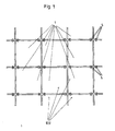
- Fig. 1 schematically shows a section of a building facade according to the invention, in which the individual, the building facade forming plates 1 are fixed by means of inventive arrangements or support body 3 on the clad and thus no longer visible from the outside building wall 2.
- the support members 3 Of the support members 3, only the front stops 5 are visible to which the plates 1 are supported with their sides facing away from the building wall 2 sides 10 and the wall 17 facing away from the building wall 2.
- the front stops 5 prevent the plates 1 can fall off the facade and make it possible to form the building facade in the vertical, horizontal but also at other angles.
- a frameless construction is possible by the front stops 5 in the form shown, which allows a particularly aesthetic design of the building facades.
- the plates 1 may be different plates of different materials with different thicknesses 16.
- some of the plates 1 may be formed as solar panels for generating electric power and / or hot water, while adjacent plates may be sheet, wood, stone, cement, composite or glass plates or the like. Due to the use of arrangements according to the invention for fastening the panels 1 to the building wall 2, it becomes possible, despite different thicknesses of the panels, to arrange their surfaces 17 facing away from the building wall 2 in a common plane 18.
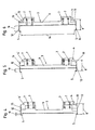
- This common level 18 is in Fig. 3 shown.
- the plates shown 1 are the same thickness.
- a support body 3 is shown.
- Fig. 4 is a comparatively small distance 19 between the front stop 5 and 6 backlash adjusted. This distance 19 is selected when relatively thin plates 1 are to be attached to the support body 3.
- Fig. 5 shows a mean distance 19 for medium-thick plates and
- Fig. 6 shows a large distance 19 between the front stop 5 and the back stop 6, which is selected when correspondingly thick plates 1 between front stop. 5 and back stop 6 are to be arranged or clamped.
- the distance 8 between the front stop 5 and fastening device 4 the same size, which ensures that the side facing away from the building wall 2 surfaces 17 of the individual plates 1 are despite their different thicknesses 16 in the common plane 18 of the building facade.
- the support body 3 of the embodiment shown each have two separate base body 13. Of course, this is just a design variant. It may also be a continuous one-piece main body 13 or more than two main body 13. In any case, a fastening device 4 or 4 ', which serves for the direct or indirect fastening of the supporting body 3 to the building wall 2, is in each case arranged on the base bodies 13 of the variant shown.
- the front stops 5 are each formed in the embodiment shown as part of a hook 12 and fixed to the respective base body 13.
- the back stops 6 are formed in the embodiment shown as strips.
- the adjusting devices 7 are provided, with which the relative position between the back stop 6 and the base bodies 13 can be changed or adjusted so as to different distances 19 between front stop. 5 and set back stop 6.
- the adjusting 7 allow fixing a distance once set and thereby also pinching the respective plate 1 between the front stopper 5 and 6 backstop. In the illustrated embodiment, it is at the adjustment 7 slots, are passed through the clamping screws. If the clamping screws are open, the relative position between the base body 13 and the back stop 6 can be adjusted. If the desired distance 19 is set between the front stop 5 and the back stop 6 or the plate 1 is clamped, then the clamping screws can be closed again, whereby the distance 19 is fixed.
- usable for this purpose adjustment 7 can be used instead of the illustrated slot lock screw combination.
- a respective support body 3 has two front stops 5 arranged in opposite end regions of the support body 3.
- the back stop 6 is arranged in the area between the front stops 5.
- the backstop extends over at least 50%, preferably over at least 80%, of the distance 14 between the two front stops 5.
- the adjustability of the distances 19 may be performed over a wide range in embodiments of the invention.
- the distances 19 between 1 mm and 120mm, preferably between 6mm and 40mm are adjustable. In the exemplary embodiment shown, this is achieved in a simple manner by forming the adjusting device 7 with correspondingly long oblong holes.
- one of the fastening devices 4 of a support body 3 is formed in each case as part of a pivot joint 15.
- this plate 1 together with the support body (s) 3 of the in Fig. 2 shown in the in Fig. 3 be pivoted position shown.
- the second, designed as a locking device fastening means 4 ' is closed, whereby the plate 1 is fully assembled to the building wall 2.
- a groove is formed as part of the locking device of the fastening device 4 'on the corresponding base body 13 of the supporting body 3, in which the bolt 20 engages in the fully assembled state.
- the bolt 20 is in a suitable manner, for example by tightening attached to the rail 9.
- the latch 20 may be designed to be pivotable in order to be able to be pivoted into the groove of the fastening device 4 '. But it is also possible as another example, the latch 20 form a plate so that it can first be inserted into the groove of the fastening device 4 'and after pivoting of the supporting body 3 in the in Fig. 3 shown end position is secured to the rail 9, for example by screwing.
- a corresponding tool such as a screwdriver, can be inserted into the respective gap between the plates 1 or front stops 5.
- Fig. 7 shows in a schematic section along the section line 21 from Fig. 3 as an example of how the latch 20 in the groove of the fastening device 4 'can be set without play. This serves to ensure that the plate does not move or is secured without play when the fastening device 4 'is closed in the assembled state. In the embodiment shown, this is achieved by the biasing spring 22 fixed to the base body 13, which presses or biases the bolt 20 against one of the boundaries of the groove of the fastening device 4 '.
- the fastening device 4 and 4 ' form such that they fasten the supporting body 3 and thus the plate 1 directly to the building wall 2.
- the fastening devices 4 and 4 'could project beyond the plates and have holes, by means of which they can be screwed to the building wall 2, to name just one of many possible embodiments of direct attachment.
Landscapes
- Engineering & Computer Science (AREA)
- Chemical & Material Sciences (AREA)
- Physics & Mathematics (AREA)
- Life Sciences & Earth Sciences (AREA)
- Sustainable Development (AREA)
- Sustainable Energy (AREA)
- Thermal Sciences (AREA)
- Architecture (AREA)
- Combustion & Propulsion (AREA)
- Mechanical Engineering (AREA)
- General Engineering & Computer Science (AREA)
- Civil Engineering (AREA)
- Structural Engineering (AREA)
- Finishing Walls (AREA)
Applications Claiming Priority (1)
| Application Number | Priority Date | Filing Date | Title |
|---|---|---|---|
| AT0029910A AT509506B1 (de) | 2010-02-25 | 2010-02-25 | Anordnung zur befestigung zumindest einer platte an einer gebäudewand |
Publications (1)
| Publication Number | Publication Date |
|---|---|
| EP2362034A2 true EP2362034A2 (fr) | 2011-08-31 |
Family
ID=43983262
Family Applications (1)
| Application Number | Title | Priority Date | Filing Date |
|---|---|---|---|
| EP11001396A Withdrawn EP2362034A2 (fr) | 2010-02-25 | 2011-02-21 | Agencement de fixation d'au moins une plaque sur une paroi de bâtiment |
Country Status (2)
| Country | Link |
|---|---|
| EP (1) | EP2362034A2 (fr) |
| AT (1) | AT509506B1 (fr) |
Cited By (5)
| Publication number | Priority date | Publication date | Assignee | Title |
|---|---|---|---|---|
| WO2016102452A1 (fr) * | 2014-12-22 | 2016-06-30 | Petrus Paulus Carolus Maria Stassen | Système de couverture de toit ou de mur, panneau et procédé d'installation de panneaux |
| US10505492B2 (en) | 2016-02-12 | 2019-12-10 | Solarcity Corporation | Building integrated photovoltaic roofing assemblies and associated systems and methods |
| WO2024251762A1 (fr) | 2023-06-07 | 2024-12-12 | Saint-Gobain Glass France | Habillage de batiment comportant une structure de fixation de panneau reglable en position et procede d'installation d'un tel habillage sur un batiment |
| FR3149632A1 (fr) * | 2023-06-07 | 2024-12-13 | Saint-Gobain Glass France | Habillage de batiment comportant une structure de fixation de panneau reglable en position et procede d’installation d’un tel habillage sur un batiment |
| FR3159813A1 (fr) | 2024-03-04 | 2025-09-05 | Saint Gobain Glass France | Habillage de batiment comportant une structure de fixation de panneau reglable en position et procede d’installation d’un tel habillage sur un batiment |
Families Citing this family (1)
| Publication number | Priority date | Publication date | Assignee | Title |
|---|---|---|---|---|
| DE102014011364B4 (de) | 2014-08-05 | 2020-01-09 | Manz Cigs Technology Gmbh | Befestigungssystem zur Befestigung von plattenförmigen Fassadenelementen |
Citations (4)
| Publication number | Priority date | Publication date | Assignee | Title |
|---|---|---|---|---|
| DE4228661A1 (de) | 1992-08-28 | 1994-03-10 | Franz Leininger | Wandverkleidungsplatte für ein Gebäude |
| DE29602772U1 (de) | 1996-02-16 | 1996-04-04 | Greten, Alfons, 49632 Essen | Verbindungsschiene für Verkleidungsplatten |
| DE19751820A1 (de) | 1996-12-03 | 1998-06-10 | Werkstaette Liechtblick | Haltevorrichtung für vorgehängte Wandverkleidungsplatten |
| DE20107121U1 (de) | 2001-03-18 | 2001-07-05 | HKR Systembau GmbH, 15711 Schenkendorf | Fassade und Vorrichtung zur Befestigung von Fassadenbekleidungsplatten |
-
2010
- 2010-02-25 AT AT0029910A patent/AT509506B1/de not_active IP Right Cessation
-
2011
- 2011-02-21 EP EP11001396A patent/EP2362034A2/fr not_active Withdrawn
Patent Citations (4)
| Publication number | Priority date | Publication date | Assignee | Title |
|---|---|---|---|---|
| DE4228661A1 (de) | 1992-08-28 | 1994-03-10 | Franz Leininger | Wandverkleidungsplatte für ein Gebäude |
| DE29602772U1 (de) | 1996-02-16 | 1996-04-04 | Greten, Alfons, 49632 Essen | Verbindungsschiene für Verkleidungsplatten |
| DE19751820A1 (de) | 1996-12-03 | 1998-06-10 | Werkstaette Liechtblick | Haltevorrichtung für vorgehängte Wandverkleidungsplatten |
| DE20107121U1 (de) | 2001-03-18 | 2001-07-05 | HKR Systembau GmbH, 15711 Schenkendorf | Fassade und Vorrichtung zur Befestigung von Fassadenbekleidungsplatten |
Cited By (6)
| Publication number | Priority date | Publication date | Assignee | Title |
|---|---|---|---|---|
| WO2016102452A1 (fr) * | 2014-12-22 | 2016-06-30 | Petrus Paulus Carolus Maria Stassen | Système de couverture de toit ou de mur, panneau et procédé d'installation de panneaux |
| NL1041128B1 (en) * | 2014-12-22 | 2016-10-11 | Ing Petrus Paulus Carolus Maria Stassen | A roof or wall covering system, a panel and method for installing panels. |
| US10505492B2 (en) | 2016-02-12 | 2019-12-10 | Solarcity Corporation | Building integrated photovoltaic roofing assemblies and associated systems and methods |
| WO2024251762A1 (fr) | 2023-06-07 | 2024-12-12 | Saint-Gobain Glass France | Habillage de batiment comportant une structure de fixation de panneau reglable en position et procede d'installation d'un tel habillage sur un batiment |
| FR3149632A1 (fr) * | 2023-06-07 | 2024-12-13 | Saint-Gobain Glass France | Habillage de batiment comportant une structure de fixation de panneau reglable en position et procede d’installation d’un tel habillage sur un batiment |
| FR3159813A1 (fr) | 2024-03-04 | 2025-09-05 | Saint Gobain Glass France | Habillage de batiment comportant une structure de fixation de panneau reglable en position et procede d’installation d’un tel habillage sur un batiment |
Also Published As
| Publication number | Publication date |
|---|---|
| AT509506B1 (de) | 2012-01-15 |
| AT509506A1 (de) | 2011-09-15 |
Similar Documents
| Publication | Publication Date | Title |
|---|---|---|
| AT509506B1 (de) | Anordnung zur befestigung zumindest einer platte an einer gebäudewand | |
| DE102009030799A1 (de) | Befestigungselement | |
| DE102009030635B4 (de) | Haltewinkel für ein Fassadensystem | |
| EP2681772B1 (fr) | Dispositif pour fixer des modules solaires sur une façade | |
| DE102011000991A1 (de) | Wandhalterung für ein selbsttragendes, plattenförmiges Bauteil, insbesondere für ein Vordach, und Montageverfahren | |
| EP2982812B1 (fr) | Systeme de fixation d'elements de façades en forme de plaques, procede de montage d'elements de façades en forme de plaque et façade | |
| DE10041775C1 (de) | Befestigungssystem für Wandelemente an Gebäudewänden | |
| EP1439269B1 (fr) | Etrier d'ancrage pour profilés pour installations sanitaires et chassis avec un tel étrier | |
| EP1182306B9 (fr) | Système de fixation pour éléments de mur à une façade | |
| EP0972891A2 (fr) | Dispositif pour la fixation de panneaux de verre contre des façades de bâtiments | |
| DE102008061410B4 (de) | Befestigungsanordnung zur Eckverbindung von zwei Platten | |
| DE102007037271A1 (de) | Vorrichtung zum Befestigen von plattenartigen Verkleidungselementen | |
| AT527298B1 (de) | Agraffenprofil und System umfassend Agraffenprofil und Agraffe | |
| EP2309068A2 (fr) | Elément en forme de bloc pour le support de charges sur des façades à système composites d'isolation thermique | |
| EP2407603B1 (fr) | Dispositif de montage doté d'une structure de montage et procédé de montage d'un tel dispositif de montage | |
| DE202010000993U1 (de) | Vorrichtung zur Befestigung von Bauteilen | |
| AT527515A1 (de) | Agraffe und System umfassend Agraffe und Agraffenprofil | |
| DE102017120584A1 (de) | Befestigungsvorrichtung für plattenförmige Bauelemente, insbesondere Fassadenelemente | |
| EP2586928B1 (fr) | Support de plaque en particulier pour panneaux en verre | |
| DE102009016917B3 (de) | Montage-Hilfswerkzeug und Verfahren zur Montage von Bauplatten an eine Unterkonstruktion | |
| DE202014101390U1 (de) | Winkelelement, Befestigungselement und Geländersystem | |
| DE202024105271U1 (de) | Ausgleichsbauteil für mit Abstand montiertes Gebäudeteil | |
| AT511097A4 (de) | Isolierte befestigungsvorrichtung | |
| DE102007061557A1 (de) | Langgestreckter Träger | |
| DE10212978B4 (de) | Befestigungseinheit zur höhenjustierbaren Befestigung eines Ausschlussprofils für ein Befestigungs- und/oder Laufschienenprofil an einer Rohdecke und/oder Unterkonstuktion |
Legal Events
| Date | Code | Title | Description |
|---|---|---|---|
| PUAI | Public reference made under article 153(3) epc to a published international application that has entered the european phase |
Free format text: ORIGINAL CODE: 0009012 |
|
| AK | Designated contracting states |
Kind code of ref document: A2 Designated state(s): AL AT BE BG CH CY CZ DE DK EE ES FI FR GB GR HR HU IE IS IT LI LT LU LV MC MK MT NL NO PL PT RO RS SE SI SK SM TR |
|
| AX | Request for extension of the european patent |
Extension state: BA ME |
|
| STAA | Information on the status of an ep patent application or granted ep patent |
Free format text: STATUS: THE APPLICATION IS DEEMED TO BE WITHDRAWN |
|
| 18D | Application deemed to be withdrawn |
Effective date: 20160901 |