EP2363366A1 - Dispositif de pliage de feuilles - Google Patents
Dispositif de pliage de feuilles Download PDFInfo
- Publication number
- EP2363366A1 EP2363366A1 EP11156349A EP11156349A EP2363366A1 EP 2363366 A1 EP2363366 A1 EP 2363366A1 EP 11156349 A EP11156349 A EP 11156349A EP 11156349 A EP11156349 A EP 11156349A EP 2363366 A1 EP2363366 A1 EP 2363366A1
- Authority
- EP
- European Patent Office
- Prior art keywords
- rollers
- pair
- reciprocating motion
- sheet
- contact surface
- Prior art date
- Legal status (The legal status is an assumption and is not a legal conclusion. Google has not performed a legal analysis and makes no representation as to the accuracy of the status listed.)
- Withdrawn
Links
- 230000033001 locomotion Effects 0.000 claims abstract description 25
- 230000015572 biosynthetic process Effects 0.000 claims description 5
- 230000005540 biological transmission Effects 0.000 claims description 3
- 238000005096 rolling process Methods 0.000 description 2
- 229940079593 drug Drugs 0.000 description 1
- 239000003814 drug Substances 0.000 description 1
- 238000003780 insertion Methods 0.000 description 1
- 230000037431 insertion Effects 0.000 description 1
- 238000000034 method Methods 0.000 description 1
- 230000010355 oscillation Effects 0.000 description 1
- 230000000717 retained effect Effects 0.000 description 1
- 238000006467 substitution reaction Methods 0.000 description 1
Images


Classifications
-
- B—PERFORMING OPERATIONS; TRANSPORTING
- B65—CONVEYING; PACKING; STORING; HANDLING THIN OR FILAMENTARY MATERIAL
- B65H—HANDLING THIN OR FILAMENTARY MATERIAL, e.g. SHEETS, WEBS, CABLES
- B65H45/00—Folding thin material
- B65H45/02—Folding limp material without application of pressure to define or form crease lines
- B65H45/06—Folding webs
- B65H45/10—Folding webs transversely
- B65H45/101—Folding webs transversely in combination with laying, i.e. forming a zig-zag pile
-
- B—PERFORMING OPERATIONS; TRANSPORTING
- B65—CONVEYING; PACKING; STORING; HANDLING THIN OR FILAMENTARY MATERIAL
- B65H—HANDLING THIN OR FILAMENTARY MATERIAL, e.g. SHEETS, WEBS, CABLES
- B65H45/00—Folding thin material
- B65H45/12—Folding articles or webs with application of pressure to define or form crease lines
- B65H45/20—Zig-zag folders
Definitions
- This invention relates to a machine and a method for folding sheets.
- this invention relates to a machine for folding information sheets intended for insertion in packets of medicines and the like.
- a web of paper is passed between two rollers which are shaped to match each other in such a way as to impart to the web lines for folding in alternating directions.
- the prior art folding system just described has many disadvantages, one of which is the fact that it is impossible to vary the size of the layer, since it is uniquely linked to the diameter of the rollers and the distance between the teeth/grooves made in them.
- the aim of this invention is to overcome these disadvantages by providing a device for folding sheets in superposed layers which is at the same time simple and economical to make and practical and effective to use.
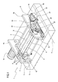
- the numeral 1 denotes in its entirety a device for folding sheets in superposed layers made in accordance with this invention.
- the device 1 comprises a supporting frame 2 which, by way of example, comprises a base 3 and two lateral walls 4a, 4b extending vertically from the base 3.
- the device 1 comprises a pair of first rollers for feeding a sheet 7, advantageously of paper, which is visible in Figures 2 to 8 .
- the pair of first rollers hereinafter also referred to without distinction as the first pair, comprises, as indicated, the two rollers 5, 6 one of which, labelled 5 in the drawings, is motor-driven, and the other of which, labelled 6, is idle.
- the two rollers 5, 6 are parallel with each other and are rotatably mounted on the vertical walls 4a, 4b of the frame 2 by means of rolling bearings of the known type and not illustrated.
- the device 1 comprises a pair of second, folding rollers 8, 9, also referred to as the second pair, which is located below the first pair.
- the second pair comprises two rollers 8, 9 which are parallel with each other and spaced with a predetermined centre-to-centre distance.
- the first rollers 5, 6 and the second rollers 8, 9 have respective axes of rotation X which are all parallel with each other.
- the two second rollers 8, 9 are free-rotatably mounted, by means of rolling bearings of the known type and not illustrated, on two sliders 10, only one of which is visible in Figure 1 , which are located at respective opposite longitudinal ends of the second rollers 8, 9 themselves.
- the device 1 comprises a contact surface 11 elastically mounted on the frame 2 by means of a plurality of elastic elements 12 of the known type, for varying its distance from the above-mentioned pair of second rollers 8, 9.
- each slider 10 slidably engages on two respective cylindrical tracks 12 which extend longitudinally in directions transversal to those identified by the axes of the rollers 5, 6, 8, 9.
- the cylindrical tracks 12 are mounted at the respective longitudinal ends on vertical members 13 which are rigidly connected to the frame 2 and, in particular, are against the vertical walls 4a, 4b.
- the sliders 10 are slidably movable relative to the frame 2, to produce a straight line reciprocating motion of the pair of second rollers 8, 9 along a direction T which is substantially perpendicular to the axes of rotation X of the rollers 5, 6, 8, 9.
- the device 1 comprises actuating means 14 designed both to make the first roller 5 rotate, thus producing a sheet 7 feeding motion, and to move the pair of second rollers 8, 9 with reciprocating motion.
- the actuating means 14 comprise a single electric motor 15 and means 16 for transmitting the motion both to the first roller 5 and to the sliders 10.
- the motion transmission means 16 comprise at least one gear wheel 17 keyed to a driving shaft 18 connected to the motor 15.
- the gear wheel 17 engages with a toothed belt 19 which transmits the rotary motion to a pulley 20 keyed to a shaft 21 integral with the first roller 5.
- the belt 19 also engages with a plurality of return rollers 22.
- the motion transmission means 16 also comprise a crank and link mechanism in turn comprising a crank 23 keyed to the driving shaft 18 and a link 24 connected to an arm 25 fixed cantilever-style to one of the sliders 10.
- the actuating means 14 have two separate motors for respectively moving the first roller 5 and the crank 23.
- the first rollers 5, 6 rotate in opposite directions, since the rotation of the first roller 5 is driven by the actuating means 14, through the belt 19 and the related pulley 20, while the roller 6 is idle, that is to say, it rotates freely.
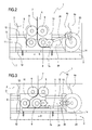
- FIG. 3 shows, when the sliders 10 invert their motion, according to the direction of the arrow D, when the crank and link mechanism reaches a dead centre, the second roller 9 makes a fold in the sheet 7, with the simultaneous formation of a second layer intended to be superposed on a first layer in contact with the contact surface 11.
- Figures 4 to 6 show successive moments of the creation of the second layer of the sheet 7, corresponding to respective successive positions of the sliders 10 as they advance along the direction indicated by the arrow D.
- Figures 3 to 6 show, in successive moments, the movement of the second rollers 8, 9 and the action of the second roller 9 on the sheet 7.
- they show how the second roller 9 lays out the sheet 7 so that it is lying on the layer below, until a superposing layer is created.
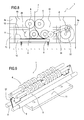
- the superposing layer is formed, in its entirety, at the moment when the pair of second rollers 8, 9 and the related sliders 10 invert their motion, as illustrated substantially in Figure 7 .
- Said figure shows the formation of a further fold in the sheet 7, said fold confirming the start of the formation of a further layer superposed on the previous layers.
- Figure 8 shows the device 1 at a moment after the configuration of Figure 7 , a moment when the sheet 7 fed by the first rollers 5, 6 and pushed by the second roller 8 on the right, rests on the second roller 9 on the left.
- the device 1 comprises an oscillating element 27 for guiding the sheet to be folded, the guide element 27 being interposed between the second rollers 8, 9.
- the presence of the oscillating element 27 advantageously allows more rapid feeding of the sheet to be folded, preventing the "natural" formation of loops in the sheet from resulting in any hindrance between the second rollers 8, 9.
- the oscillating element 27 advantageously comprises two superposed plates which are spaced by a gap big enough to allow the passage of a sheet between them.
- the means for driving the oscillation advantageously derive their motion from the crank and link mechanism which drives the reciprocating movement of the sliders 10.
Landscapes
- Folding Of Thin Sheet-Like Materials, Special Discharging Devices, And Others (AREA)
- Shaping Of Tube Ends By Bending Or Straightening (AREA)
Applications Claiming Priority (1)
| Application Number | Priority Date | Filing Date | Title |
|---|---|---|---|
| ITBO2010A000124A IT1398486B1 (it) | 2010-03-03 | 2010-03-03 | Dispositivo per la piegatura di fogli |
Publications (1)
| Publication Number | Publication Date |
|---|---|
| EP2363366A1 true EP2363366A1 (fr) | 2011-09-07 |
Family
ID=42831586
Family Applications (1)
| Application Number | Title | Priority Date | Filing Date |
|---|---|---|---|
| EP11156349A Withdrawn EP2363366A1 (fr) | 2010-03-03 | 2011-03-01 | Dispositif de pliage de feuilles |
Country Status (2)
| Country | Link |
|---|---|
| EP (1) | EP2363366A1 (fr) |
| IT (1) | IT1398486B1 (fr) |
Cited By (2)
| Publication number | Priority date | Publication date | Assignee | Title |
|---|---|---|---|---|
| US20110306482A1 (en) * | 2009-02-18 | 2011-12-15 | Sprick Gmbh Bielefelder Papierund Wellpappenwerke & Co. | Drive mechanism for a device for laying a fibrous material web in a leporello fold |
| CN115195090A (zh) * | 2022-06-28 | 2022-10-18 | 陕西臻瑞汽车部件有限公司 | 一种热片材铺料设备 |
Citations (4)
| Publication number | Priority date | Publication date | Assignee | Title |
|---|---|---|---|---|
| JPS58100065A (ja) * | 1981-12-09 | 1983-06-14 | Hiroshi Hatahara | 帯状紙のジグザグ折り曲げ方法 |
| US4573958A (en) * | 1984-05-08 | 1986-03-04 | Biesinger Peter J | Cuttling machine for continuous input of web |
| US4573670A (en) * | 1983-12-07 | 1986-03-04 | Jos. Hunkeler Ltd. | Apparatus for folding and stacking of continuous web in zigzag arrangement |
| WO1999016693A1 (fr) * | 1997-09-29 | 1999-04-08 | Stac Pac Technologies Inc. | Appareil d'emballage d'une bande de matiere |
-
2010
- 2010-03-03 IT ITBO2010A000124A patent/IT1398486B1/it active
-
2011
- 2011-03-01 EP EP11156349A patent/EP2363366A1/fr not_active Withdrawn
Patent Citations (4)
| Publication number | Priority date | Publication date | Assignee | Title |
|---|---|---|---|---|
| JPS58100065A (ja) * | 1981-12-09 | 1983-06-14 | Hiroshi Hatahara | 帯状紙のジグザグ折り曲げ方法 |
| US4573670A (en) * | 1983-12-07 | 1986-03-04 | Jos. Hunkeler Ltd. | Apparatus for folding and stacking of continuous web in zigzag arrangement |
| US4573958A (en) * | 1984-05-08 | 1986-03-04 | Biesinger Peter J | Cuttling machine for continuous input of web |
| WO1999016693A1 (fr) * | 1997-09-29 | 1999-04-08 | Stac Pac Technologies Inc. | Appareil d'emballage d'une bande de matiere |
Cited By (3)
| Publication number | Priority date | Publication date | Assignee | Title |
|---|---|---|---|---|
| US20110306482A1 (en) * | 2009-02-18 | 2011-12-15 | Sprick Gmbh Bielefelder Papierund Wellpappenwerke & Co. | Drive mechanism for a device for laying a fibrous material web in a leporello fold |
| US9061860B2 (en) * | 2009-02-18 | 2015-06-23 | Sprick Gmbh Bielefelder Papier-Und Wellpappenwerke & Co. | Drive mechanism for a device for laying a fibrous material web in a Leporello fold |
| CN115195090A (zh) * | 2022-06-28 | 2022-10-18 | 陕西臻瑞汽车部件有限公司 | 一种热片材铺料设备 |
Also Published As
| Publication number | Publication date |
|---|---|
| IT1398486B1 (it) | 2013-03-01 |
| ITBO20100124A1 (it) | 2011-09-04 |
Similar Documents
| Publication | Publication Date | Title |
|---|---|---|
| DE602004006993T2 (de) | Schneidwerk für eine hülsen-wickelmaschine mit einem an einem rotierendem arm geführten schneider | |
| US20130305891A1 (en) | Web member cutting apparatus for cutting web member that has a plurality of fibers including tows and web member cutting method | |
| JPS5843292B2 (ja) | カミタバ マタハ ソノルイジブツノラツピングソウチ | |
| US8083661B2 (en) | Creasing machine | |
| JP2011063443A5 (fr) | ||
| US3972519A (en) | Apparatus for the zig-zag folding of a web of material | |
| CN106687262A (zh) | 用于通过将带状体材料卷绕一成型芯轴来生产管体的机器 | |
| EP2363366A1 (fr) | Dispositif de pliage de feuilles | |
| DE60316817T2 (de) | Verpackungsmaschine für die Produktumwicklung in korrespondierenden Zuschnitten aus heisssiegelbarem Umwicklungsmaterial | |
| JP5883747B2 (ja) | フォルダグルア | |
| JP6178124B2 (ja) | 切断装置及び切断方法 | |
| JPH05104321A (ja) | 切断機 | |
| JP3416852B2 (ja) | ポケットコイルばねの製造方法およびその装置 | |
| US1693728A (en) | Material-feeding device | |
| KR101133161B1 (ko) | 제본기의 접지장치 | |
| JP2004142836A (ja) | 折機のデリバリー装置 | |
| ITBO20080167A1 (it) | Unita' operatrice per macchine interfogliatrici. | |
| JP2571216B2 (ja) | ばね巻付け機 | |
| EP2090535A1 (fr) | Dispositif pour couper transversalement une bande. | |
| KR200428871Y1 (ko) | 직물지 절단 장치 | |
| EP1364901A2 (fr) | Appareil de sortie de feuilles | |
| JP2017081619A (ja) | 折り目形成装置、ピロー包装機、包装材、包装方法およびピロー包装体 | |
| CN207943625U (zh) | 一种平压平模切机的输纸机构 | |
| US1652093A (en) | Means for cutting fabrics into lengths or portions | |
| US3468202A (en) | Machine for cutting flat flexible multiwall tubing |
Legal Events
| Date | Code | Title | Description |
|---|---|---|---|
| PUAI | Public reference made under article 153(3) epc to a published international application that has entered the european phase |
Free format text: ORIGINAL CODE: 0009012 |
|
| AK | Designated contracting states |
Kind code of ref document: A1 Designated state(s): AL AT BE BG CH CY CZ DE DK EE ES FI FR GB GR HR HU IE IS IT LI LT LU LV MC MK MT NL NO PL PT RO RS SE SI SK SM TR |
|
| AX | Request for extension of the european patent |
Extension state: BA ME |
|
| STAA | Information on the status of an ep patent application or granted ep patent |
Free format text: STATUS: THE APPLICATION IS DEEMED TO BE WITHDRAWN |
|
| 18D | Application deemed to be withdrawn |
Effective date: 20120308 |