EP2363714A2 - Probenanalysegerät, Verfahren und Vorrichtung zum Erhalt von Informationen zur Probenidentifikation - Google Patents
Probenanalysegerät, Verfahren und Vorrichtung zum Erhalt von Informationen zur Probenidentifikation Download PDFInfo
- Publication number
- EP2363714A2 EP2363714A2 EP11156751A EP11156751A EP2363714A2 EP 2363714 A2 EP2363714 A2 EP 2363714A2 EP 11156751 A EP11156751 A EP 11156751A EP 11156751 A EP11156751 A EP 11156751A EP 2363714 A2 EP2363714 A2 EP 2363714A2
- Authority
- EP
- European Patent Office
- Prior art keywords
- sample
- barcode
- reading
- sample container
- barcode reader
- Prior art date
- Legal status (The legal status is an assumption and is not a legal conclusion. Google has not performed a legal analysis and makes no representation as to the accuracy of the status listed.)
- Granted
Links
Images


Classifications
-
- G—PHYSICS
- G01—MEASURING; TESTING
- G01N—INVESTIGATING OR ANALYSING MATERIALS BY DETERMINING THEIR CHEMICAL OR PHYSICAL PROPERTIES
- G01N35/00—Automatic analysis not limited to methods or materials provided for in any single one of groups G01N1/00 - G01N33/00; Handling materials therefor
- G01N35/00584—Control arrangements for automatic analysers
- G01N35/00722—Communications; Identification
- G01N35/00732—Identification of carriers, materials or components in automatic analysers
- G01N2035/00742—Type of codes
- G01N2035/00752—Type of codes bar codes
Definitions
- the present invention relates to a sample analyzer which analyzes a sample contained in a sample container, a method of obtaining sample identification information to obtain identification information of a sample contained in a sample container by reading a barcode adhered to the sample container, and an sample identification information obtaining apparatus.
- sample analyzes for processing clinical samples such as blood or urine are being used in medical centers.
- a configuration for obtaining identification information of a sample contained in a sample container by reading a barcode adhered to the sample container is provided.
- the barcode adhered to a sample container is read while a sample container is rotated.
- the identification information of the sample is obtained on the basis of this barcode information.
- a sample container may be moved from a medical center to another medical center.
- the identification information of a sample is newly assigned in the medical center after the transfer.
- a new barcode is issued on the basis of the newly assigned identification information and is adhered to the sample container.
- the new barcode is adhered over the barcode which is adhered in the medical center before the transfer.
- a first aspect of the present invention is a sample analyzer comprising: a measurement unit for measuring a sample contained in a sample container; a barcode reader for reading a barcode adhered to the sample container by irradiating a side surface of the sample container with light; a rotating section for rotating the sample container relative to the barcode reader so that a position at which the reading is performed by the barcode reader moves in a circumferential direction of the sample container; and a controller which executes operations, the operations comprising: controlling the rotating section and the barcode reader so that the barcode reader repeatedly reads the barcode over the range of a predetermined rotation angle; and obtaining identification information of the sample contained in the sample container on the basis of reading results obtained as a result of the repeated reading of the barcode by the barcode reader.
- the sample analyzer even in the case of a sample container to which barcodes are doubly adhered, as well as the old barcode exposed from the lower side, the new barcode adhered on the upper side is also read and the reading results are obtained. Therefore, obtaining wrong identification information due to the reading of only the old barcode exposed from the lower side can be avoided and accurate identification information can be obtained.
- the controller causes the barcode reader to repeatedly read the barcode at least while the sample container is rotated 360 degrees.
- the new barcode is necessarily read over a large area no matter how the barcode is adhered. Accordingly, the accuracy of the obtained identification information can be increased.
- the controller causes the barcode reader to repeatedly read the barcode at least while the sample container is rotated by 180 degrees, or, that the controller causes the barcode reader to repeatedly read the barcode at least while the sample container is rotated by 270 degrees.
- the controller controls rotating section to terminates the rotation and controls the barcode reader to terminates the reading.
- the controller obtains the identification information of the sample contained in the sample container on the basis of one reading result which occupies a predetermined ratio among the plurality of reading results.
- the controller retries the controlling operation and the obtaining operation when a number of the reading results does not satisfy a first threshold.
- the controller obtains the identification information on the basis of one reading result which is continuously read.
- the controller retries the causing operation and the obtaining operation when the controller fails to obtain identification information.
- the controller controls the rotating section so that the rotation of the retried operation is performed in a direction reverse against a direction of an initial rotation.
- the sample container is smoothly rotated due to the reverse rotation of the sample container. Accordingly, the barcode reading can be smoothly performed. Therefore, it is possible to increase a possibility of properly reading the barcode during the re-reading.
- the controller controls the rotating section so that the rotation of the retried operation is performed at a speed lower than the rotation speed in the initial rotation.
- the rotating section includes at least three rollers and rotates the sample container by rotating any one of the rollers in a state in which the rollers are brought into contact with the sample container.
- the sample container is a vacuum blood collection tube
- the measurement unit measures blood cells included in blood as a sample which is contained in a vacuum blood collection tube.
- a second aspect of the present invention is method of obtaining sample identification information, the method comprising: repeatedly reading a barcode adhered to a sample container over a range of a predetermined rotation angle by rotating the sample container; and obtaining identification information of a sample contained in the sample container on the basis of reading results obtained as a result of the repeated reading of the barcode.
- a third aspect of the present invention is a sample identification information obtaining apparatus comprising: a barcode reader for reading a barcode adhered to the sample container by irradiating a side surface of the sample container with light; a rotating section for rotating the sample container relative to the barcode reader so that a position at which the reading is performed by the barcode reader moves in a circumferential direction of the sample container; and a controller which executes operations, the operations comprising: controlling the rotating section and the barcode reader so that the barcode reader repeatedly reads the barcode over the range of a predetermined rotation angle; and obtaining identification information of the sample contained in the sample container on the basis of reading results obtained as a result of repeated reading of the barcode by the barcode reader.
- This embodiment is a sample analysis system for examination and analysis related to blood, to which the invention is applied.
- a sample analysis system according to this embodiment includes three measurement units and one smear preparation apparatus. In the three measurement units, blood analysis is performed concurrently, and when it is necessary to prepare a smear based on the analysis result thereof, the smear preparation apparatus prepares a smear.
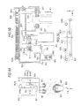
- Fig. 1 is a plan view schematically showing the configuration when a sample analysis system 1 is viewed from the upper side.
- the sample analysis system 1 according to this embodiment is configured to include a sample recovery unit 21, a sample insertion unit 22, a sample output unit 23, three sample transport units 3, a blood cell analysis apparatus 4, a sample transport unit 5, a smear preparation apparatus 6, and a transport controller 7.
- the sample analysis system 1 of this embodiment is connected to a host computer 8 via a communication network so as to communicate therewith.
- Each of the sample recovery unit 21, the sample insertion unit 22, and the sample output unit 23 is configured so that a plurality of sample racks can be placed therein.
- Fig. 2 shows the configurations of a sample container T and a sample rack L.
- Fig. 2A is a perspective view showing the appearance of a sample container T and
- Fig. 2B is a front view of a sample rack L.
- a sample container T is a tubular container (vacuum blood collection tube) made of glass or a synthetic resin having translucency.
- the upper end of the container is opened and the opening is sealed by a cap section CP.
- a barcode label BL1 is adhered to a side surface of the sample container T.
- On the barcode label BL1, a barcodes showing a sample ID is printed.
- the sample container T a blood sample collected from a patient is contained and the opening of the upper end is sealed by the cap section CP.
- the cap section CP In the cap section CP, a hole is formed in the vertical direction so that a pipette passes therethrough.
- a barcode label BL2 is adhered to a surface (surface in the Y-axis negative direction) on the inward side when the sample rack L is set in the sample insertion unit 22.
- a barcode showing a rack ID is printed on the barcode label BL2
- the sample recovery unit 21 stores sample racks L in which analysis has ended.
- the sample insertion unit 22 stores sample racks L which are inserted by a user and outputs the stored sample racks L toward the sample output unit 23 from the innermost position (end in the Y-axis negative direction) in the leftward direction (in the X-axis positive direction).
- the sample recovery unit 21 and the sample insertion unit 22 are connected to the transport controller 7 so as to communicate therewith.
- the sample output unit 23 has a sensor 23a which is installed on the left side of the innermost position and a barcode unit B which is installed on the innermost side.
- the sensor 23a detects a sample rack L output from the sample insertion unit 22 and positioned on the innermost side of the sample output unit 23.
- the barcode unit B reads a rack ID of the sample rack L positioned on the innermost side and a sample ID of a sample container T held in this sample rack L.
- sample output unit 23 outputs a sample rack L in which the reading of the barcode has been completed to the sample transport unit 3. Further, the sample output unit 23 is connected to the transport controller 7 so as to communicate therewith and the rack ID and the sample ID read by the sample output unit 23 are transmitted to the transport controller 7.
- the configuration of the barcode unit B will be described later with reference to Fig. 4 .
- the three sample transport units 3 are disposed in front of three measurement units 41 (in the Y-axis positive direction), respectively, as shown in Fig. 1 .
- the neighboring two sample transport units 3 are connected to each other so as to deliver sample racks L.
- the right end of the sample transport unit 3 on the right side (X-axis negative direction) is connected to the sample output unit 23 so as to deliver sample racks L, and the left end of the sample transport unit 3 on the left side (in the X-axis positive direction) is connected to the sample transport unit 5 so as to deliver sample racks L.
- the three sample transport units 3 are respectively connected to an information processing unit 42 and the transport controller 7 so as to communicate therewith.
- two transport lines L1 and L2 for transporting the sample racks L are set by dividing cases into the cases in which the measurement of a sample is performed in the respective corresponding measurement units 41 and the cases in which the measurement is not performed. That is, when the measurement of a sample is performed by the measurement unit 41, a sample rack is transported along the transport line L1 shown by the U-shaped rear arrow. When the measurement of a sample is not performed in the measurement unit 41, a sample rack L is transported along the transport line L2 shown by the intermediate left-pointing arrow so as to skip the present measurement unit 41.
- a transport line L3 for transporting the sample racks L to the sample recovery unit 21 is set as shown in Fig. 1 . That is, a sample rack L, in which measurement has ended or preparation of a smear has ended, is transported along the transport line L3 shown by the front (in the Y-axis positive direction) right-pointing (in the X-axis negative direction) arrow and is recovered by the sample recovery unit 21.
- the blood cell analysis apparatus 4 is an optical flow cytometry type multiple blood cell analysis apparatus and includes the three measurement units 41 and the information processing apparatus 42.
- Each of the three measurement units 41 has a barcode unit C and measures a blood sample which is contained in a sample container T.
- the information processing unit 42 is connected to the three measurement units 41 so as to communicate therewith and control the operations of the three measurement units 41.
- the information processing unit 42 is also connected to the three sample transport units 3 so as to communicate therewith.
- Fig. 3 is a plan view schematically showing the configuration when the measurement unit 41 is viewed from the upper side.
- a hand section 411a installed at the front end of a sample container transport section 411 grips a sample container T which is held in a sample rack L at a predetermined position on the transport line L1 and takes it upward (in the Z-axis positive direction).
- the taken sample container T is stirred by the hand section 411a and then set in a sample container setting section 411b.
- the sample container setting section 411b is configured to be moved in the Y-axis direction by a transport mechanism section 411c.
- the transport mechanism section 411c includes a belt, two pulleys, and a stepping motor (not shown).
- the sample container T set in the sample container setting section 411b is positioned in front of the barcode uni t C (in the X-axis negative direction) due to the backward movement (Y-axis negative direction) of the sample container setting section 411b.
- the barcode unit C reads a sample ID of the sample container T. Such a sample ID is transmitted to the information processing unit 42.
- the configuration of the bar-code unit C will be described later with reference to Fig. 4 .
- the information processing unit 42 inquires of the host computer 8 for a measurement order. On the basis of the result of such inquiry, the measurement of the sample which is contained in the sample container T is instructed by the information processing unit 42.
- the sample container T is positioned under a sample suction section 412 (in the Z-axis negative direction) due to the backward movement or the sample container setting section 411b.
- the sample suction section 412 suctions the sample in the sample container T which is positioned under the sample suction section 412. After that, the sample container T returns along the original course and returns to the original holding position in the sample rack L.
- a specimen adjustment section 413 has a plurality of reaction chambers (not shown). The specimen adjustment section 413 mixes and stirs a reagent and the sample suctioned by the sample suction section 412 in a reaction chamber and prepares a specimen for measurement. A detecting section 414 measures the specimen prepared by the specimen adjustment section 413. The measurement data obtained by such measurement is analyzed by the information processing unit 42.
- the sample transport unit 5 is disposed in front of the smear preparation apparatus 6 (in the Y-axis positive direction). As in the sample transport unit 3, in the sample transport unit 5, transport lines L1, L2 and L3 are set. In addition, the sample transport unit 5 is connected to the transport controller 7 so as to communicate therewith. Further, the sample transport unit 5 is connected to the smear preparation apparatus 6, and in accordance with an instruction from the sample transport unit 5, the smear preparation apparatus 6 is driven.
- the sample transport unit 5 has a barcode unit D near the transport line L1.
- the barcode unit D reads the rack ID of a sample rack L positioned in front of the barcode unit D and a sample ID of a sample container T associated with the holding section in the sample rack L.
- the configuration of the barcode unit D will be described later with reference to Fig. 4 .
- the sample transport unit 5 has a transport mechanism for transporting a sample rack L along the transport line L1.
- This transport mechanism includes a belt, two pulleys, and a stepping motor (not shown) in order to transport a sample rack L in the right- and leftward directions (in the X-axis direction) immediately in front of the smear preparation apparatus 6 (in the Y-axis positive direction).
- a smear of a blood sample is prepared. That is, first, the smear preparation apparatus 6 suctions a blood sample contained in a sample container T at a predetermined position on the transport line L1 of the sample transport unit 5. Next, the suctioned blood sample is dropped onto a glass slide, thinly extended on the glass slide, and then is dried. After that, a liquid dye is supplied to the glass slide to dye the blood on the glass slide and a smear is prepared.
- Whether the preparation of a smear is required is determined by the transport controller 7 on the basis of the result of the analysis which is performed by the information processing unit 42, based on the result of the measurement in the three measurement units 41.
- the result of the analysis which is performed by the information processing unit 42 is transmitted to the transport controller 7 via the sample transport unit 3.
- the transport controller 7 determines that the preparation of a smear is required, the sample rack L storing a target sample is transported along the transport line L1 of the sample transport unit 5 and a smear is prepared in the smear preparation apparatus 6.
- the transport controller 7 is connected to the sample recovery unit 21, the sample insertion unit 22, the sample output unit 23, the three sample transport units 3, and the sample transport unit 5 so as to communicate therewith and controls the driving of each unit.
- the transport controller 7 for example, a separate personal computer or a computer incorporated in the system is used.
- the transport controller 7 inquires of the host computer 8 for a measurement order.
- the transport controller 7 stores the measurement order in association with the rack ID, the sample ID and the holding position.
- the transport controller 7 determines whether a sample rack L which is output from the sample output unit 23 is transported to any of the three measurement units 41.
- the transport controller 7 transmits the stored measurement order to the sample transport unit 3 in front of the measurement unit 41 which is determined as a transport destination.
- the transport controller 7 controls each sample transport unit 3 so as to transport this sample rack L up to the measurement unit 41 which is determined as a transport destination.
- the host computer 8 is connected to the communication network and can communicate with the information processing unit 42 and the transport controller 7. In a storage section of the host computer 8, measurement orders are stored. When the information processing unit 42 or the transport controller 7 requests a measurement order including a sample ID, the host computer 8 reads out the measurement order corresponding to this sample ID from the storage section and transmits the measurement order to the information processing unit 42 or the transport controller 7.
- Fig. 4 shows plan views schematically showing the configurations when the barcode units A, B and C are viewed from the upper side, respectively.
- Fig. 4A is a view showing the barcode unit B.
- the barcode unit B has two reading sections B1 and B2 which are juxtaposed in the horizontal direction (in the X-axis direction).
- Each or the reading sections B1 and B2 includes two rollers B11, a roller B21, a base B30, and a barcode reader B31.
- the two rollers B11 are configured to rotate around the Z axis and to be moved in the Y-axis direction on the base B30.
- the roller B21 is configured to rotate and be driven around the Z axis and is fixed on the base B30.
- the barcode reader B31 is fixed to the base B30 and reads a barcode which is positioned immediately ahead thereof (in the Y-axis positive direction).
- the base B30 is configured to be moved in the horizontal direction.
- a mechanism for driving the rollers B11 and B21 and the base B30 is disposed on the innermost side of the sample output unit 23 (inward side of the sample rack L in Fig. 4A ).
- the two rollers B11 are moved forward (in the Y-axis positive direction) so as to be brought into contact with the side surface of the sample container T as shown in Fig. 4B .
- the side surface of the sample container T on the nearest side is brought into contact with the roller B21.
- the sample container T is rotated around the Z axis and the barcode label BL1 is read multiple times by the barcode reader B31 during the rotation of the sample container T.
- the barcode reader B31 reads the barcode label BL2 (see Fig. 2B ) , which is adhered between the holding sections 1 and 2 in the sample rack L, the rollers B11 are not driven forward.
- the barcode readers B31 of the reading sections B1 and B2 read the rack ID of the sample rack L and the sample IDs of sample containers T as shown in Fig. 4B .
- the barcode readers 31 of the reading sections B1 and B2 read the barcodes in order from the left.
- the barcode reader 31 of the reading section B1 By the barcode reader 31 of the reading section B1, the rack ID of the sample rack L, and the sample IDs of the sample containers T which are held in the left-half portion (holding sections 1 to 5) of the sample rack L are read, and by the barcode reader 31 of the reading section B2, the rack IDs of the sample containers T which are held in the right-half portion (holding sections 6 to 10) of the sample rack L are read.
- the barcode portion of the barcode label BL1 adhered to the sample container T is limited to a part of the outer circumference around the Z axis. For this reason, even when the sample container T is rotated, when a positional relationship in which the barcode portion of the sample container T and the barcode reader B31 are opposed to each other is not achieved during the reading operation of the barcode reader B31, the barcode is not read by the barcode reader B31.
- the sample container T is rotated once. Accordingly, the barcode portion of the sample container T necessarily meets the barcode reader B31 and the barcode is read.
- Fig. 4C is a view showing the barcode unit C.
- the barcode unit C includes two rollers C11, a roller C21, a base C30, and a barcode reader C31.
- the base C30 and the barcode reader C31 are fixed to the inside of the measurement unit 41.
- the sample ID of a sample container T which is positioned in front of the barcode reader C31 (in the X-axis negative direction) is read as in the barcode unit B. That is, the two rollers C11 are moved in the rightward direction (in the X-axis negative direction) and the roller C21 is rotated around the Z axis, and thus the sample container T is rotated.
- the barcode label BL1 of the sample container T is read multiple times by the barcode reader C31.
- Fig. 4D is a view showing the barcode unit D.
- the barcode unit D includes two rollers D11, a roller D21, a base D30, and a barcode reader D31.
- the base D30 and the barcode reader D31 are fixed near the transport line L1 of the sample transport unit 5.
- a mechanism for driving the rollers D11 and D21 is disposed immediately in front of a sample rack L in Fig. 4D .
- the sample ID of a sample container T which is positioned in front of the barcode reader D31 (in the Y-axis positive direction) is read as in the above-described barcode unit B. That is, the two rollers D11 are moved in the downward direction (in the Y-axis positive direction) and the roller D21 is rotated around the Z axis, and thus the sample container T is rotated. In this state, the barcode label BL1 of the sample container T is read multiple times by the barcode reader D31.
- Fig. 5 shows the configuration of the barcode unit B in detail. Since the barcode units C and D have almost the same configuration as that of the barcode unit B, only the barcode unit B will be described hereinafter.
- Fig. 5A is a plan view when the rollers B11 and B21 and the surroundings thereof are viewed from the upper side.
- Fig. 5B is a side view when the barcode unit B is viewed from the left side (in the X-axis negative direction).
- Fig. 5C is a side view when support sections B33 and B34 and the surroundings thereof are viewed from the front (in the Y-axis negative direction).
- rollers B11 and a douser B15 are mounted on a support member B10.
- Pulleys B13a and B13b, a stepping motor B14, and a sensor B16 are mounted on the base B30.
- a flange section B10a is formed in the support member B10.
- the support member B10 is supported so as to be moved in the Z-axis direction by a guide (not shown) which is installed in the base B30 and extends in the Y-axis direction.
- the two rollers B11 are supported so as to be rotated around the Z axis by the support member B10.
- a belt B12 runs on the pulleys B13a and B13b.
- the pulley B13a is installed in the shaft of the stepping motor B14 so as to be rotated around the Z axis and the pulley B13b is installed in the base B30 so as to be rotated around the Z axis.
- the flange section B10a is fixed to the belt B12 .
- the douser B15 is a flat plate having a plane perpendicular to the X axis and is installed on the lower surface of the support member B10.
- the sensor B16 is a transmission sensor and is composed of a light-emitting section B16a and a light-receiving section B16b.
- the light-emitting section B16a and the light-receiving section B16b are installed on the base B30 so as to receive the light emitted from the light-emitting section B16a by the light-receiving section B16b and to be opposed to each other in the X-axis direction.
- the belt B12 moves around the pulleys B13a and B13b due to the driving of the stepping motor B14. Accordingly, with the two rollers B11, the support member B10 moves in the Y axis direction on the base B30. In addition., with a signal which is output from the light-receiving section B16b, it is found whether or not the support member B10 is moved forward up to a position where it is determined that there is no sample container T.
- roller B21, a shaft B22 and a pulley B24b are mounted on a support member 320.
- the support member B20 is screwed to the base B30.
- the roller B21 has a hole formed therethrough in the Z axis direction.
- the shaft B22 passes through this hole and supports the roller B21.
- both ends of the shaft B22 are supported by the support member B20 so as to be rotated around the Z axis.
- a belt B23 runs on the pulleys B24a and B24b.
- the pulley B24a is installed in the shaft of a stepping motor B25 so as to be rotated around the Z axis and the pulley B24b is installed in the support member B20 and the support shaft B22 so as to be rotated around the Z axis.
- the stepping motor B25 is installed in the base B30.
- the belt B23 moves around the pulleys B24a and B24b due to the driving of the stepping motor B25. Accordingly, the shaft B22 and the roller B21 are rotated around the Z axis.
- the barcodes reader B31, a receiving section B32, two belts B35, two pulleys B36a, two pulleys B36b, and two stepping motors B37 are disposed on the lower surface of the base B30 (surface in the Z-axis negative direction).
- the barcodes reader B31 and the receiving section B32 are installed on the lower surface of the base B30.
- the support sections B33 and B34 are installed on the lower surfaces of the bases B30 of the reading sections B1 and B2, respectively.
- a guide 23c extending in the X axis direction is installed on the upper surface of a support section 23b which is installed on the innermost side (end in the Y-axis negative direction) of the sample output unit 23.
- the base B30 is supported so as to be moved in the X axis direction on the guide 23c via the receiving section B32.
- the two pulleys B36a and the two pulleys B36b are installed on the side surface of the support section 23b of the sample output unit 23 in the Y-axis negative direction so as to be rotated around the Y axis.
- the two belts B35 run on the pulleys B36a and B36b.
- the support sections B33 and B34 are fixed to the upper and lower belts B35, respectively.
- the two stepping motors B37 are installed in the support section 23b and are connected to the two pulleys B36a.
- the two belts B35 moves around the pulleys B36a and B36b due to the driving of the two stepping motors B37. Accordingly, the support sections B33 and B34 are moved in the X axis direction and thus the bases B30 of the reading sections B1 and B2 are moved individually in the X axis direction.
- Fig. 6 is a diagram showing the functional configurations of the sample output unit 23 and the transport controller 7.
- a communication section 231 performs data communication with the transport controller 7.
- a controller 232 has a storage section 232b including a CPU 232a, a ROM, a RAM, a hard disk and the like.
- the CPU 232a controls sections in accordance with a computer program which is stored in the storage section 232b.
- the CPU 232a obtains the sample ID of a sample which is contained in a sample container T on the basis of the reading result read by a barcode reader section 233. The process of obtaining a sample ID will be described later in detail with reference to Figs. 10 to 12 .
- the barcode reader section 233 includes the two barcode readers B31 which are included in the reading sections B1 and B2.
- the reading result which is output from the barcode reader section B233 is output to the controller 232.
- a driving section 234 includes the stepping motors B14, B25 and B37 which are included in the reading sections B1 and B2 and the stepping motors in other driving mechanisms.
- the driving section 234 includes a rotary encoder which is disposed in each stepping motor. The rotary encoder outputs a pulse signal corresponding to the rotation amount of the stepping motor.
- a sensor section 235 includes the sensors B16 which are included in the reading sections B1 and B2 and the sensor 23a which is disposed in the sample output unit 23. A detection signal of the sensor section 235 is output to the controller 232.
- a communication section 701 performs data communication with the sample recovery unit 21, the sample insertion unit 22, the three sample transport units 3, and the sample transport unit 5 other than the sample output unit 23.
- a controller 702 has a storage section 702b including a CPU 702a, a ROM, a RAM, a hard disk and the like. The CPU 702a controls sections in accordance with a computer program which is stored in the storage section 702b.
- a display section 703 has a display device such as a monitor.
- An input section 704 has a mouse or a keyboard.
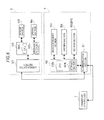
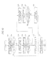
- Fig. 7 is a diagram showing the functional configurations of the sample transport unit 3, the measurement unit 41, and the information processing unit 42.
- Fig. 7 for the sake of convenience, only one sample transport unit 3 and only one measurement unit 41 are shown. However, the other sample transport units 3 and the other measurement units 41 also have the same configuration.
- a communication section 301 performs data communication between the transport controller 7 and the information processing unit 42.
- a controller 302 has a storage section 302b including a CPU 302a, a ROM, a RAM, a hard disk and the like.
- the CPU 302a controls sections in accordance with a computer program which is stored in the storage section 302b.
- a sensor section 303 includes a sensor disposed in the sample transport unit 3 and a driving section 304 includes a driving mechanism for the sample transport unit 3.
- the sections in the measurement unit 41 are controlled by a controller 422 of the information processing unit 42.
- the controller 422 of the information processing unit 42 performs data communication with the sections in the measurement unit 41 via communication sections 421 and 410 and controls the sections in the measurement unit 41.
- the measurement unit 41 includes a barcode reader section 415, a driving section 416, and a sensor section 417 in addition to the sample suction section 412, the specimen adjustment section 413, and the detecting section 414 shown in Fig. 3 .
- the barcode reader section 415 includes a barcode reader C31.
- the reading result which is output from the barcode reader section 415 is transmitted to the controller 422 of the information processing unit 42 via the communication section 410.
- the driving section 416 includes a stepping motor which is included in the barcode unit C and a rotary encoder which is disposed in the stepping motor.
- the sensor section 417 includes a sensor C16 which is included in the barcode unit C.
- the sensor C16 has the same function as that of the sensor B16 of the barcode unit B and a detection signal of the sensor section 417 is transmitted to the controller 422 of the information processing unit 42 via the communication section 410.
- the communication section 421 performs data communication between the communication section 301 of the sample transport unit 3 and the communication section 410 of the measurement unit 41.
- the controller 422 has a storage section 422b including a CPU 422a, a ROM, a RAM, a hard disk and the like.
- the CPU 422a controls the sections in the information processing unit 42 and the sections in the measurement unit 41 in accordance with a computer program which is stored in the storage section 422b.
- the CPU 422a performs blood analysis on the basis of the measurement result (particle data) which is received from the measurement unit 41 and displays the analysis result on a display section 423. Such analysis result is transmitted to the transport controller 7 via the sample transport unit 3.
- the CPU 422a inquires of the host computer 8 for a measurement order via the communication section 421. In addition, the CPU 422a obtains the sample ID of a sample which is contained in a sample container T on the basis of the reading result from the barcode reader section 415 as in the CPU 232a of the sample output unit 23.
- the display section 422 and an input section 424 have the same configurations as those of the display section 703 and the input section 704 of the transport controller 7.
- Fig. 8 is a diagram showing the functional configurations of the sample transport unit 5 and the smear preparation apparatus 6.
- a communication section 501 performs data communication between the smear preparation apparatus 6 and the transport controller 7.
- a controller 502 has a storage section 502b including a CPU 502a, a ROM, a RAM, a hard disk and the like.
- the CPU 502a controls the sections in accordance with a computer program which is stored in the storage section 502b.
- the CPU 502a obtains the sample ID of a sample which is contained in a sample container T on the basis of the reading result from a barcode reader section 503 as in the CPU 232a of the sample output unit 23.
- a driving section 504 includes a stepping motor which is included in the barcode unit D and the stepping motors in other driving mechanism.
- the driving section 504 includes rotary encoders which are disposed in the stepping motors, respectively.
- a sensor section 505 includes a sensor D16 which is included in the barcode unit D.
- the sensor D16 has the same function as that of the sensor B16 of the barcode unit B.
- the communication section 301 performs data communication with the sample transport unit 5.
- a controller 602 has a storage section 602b including a CPU 602a, a ROM, a RAM, a hard disk and the like.
- the CPU 602a controls the sections in accordance with a computer program which is stored in the storage section 602b.
- a sensor section 603 includes a sensor which is disposed in the sample transport unit 5.
- each of the barcode units B, C, and D of the sample output unit 23, the measurement unit 41, and the sample transport unit 5 reads the barcode label BL1 multiple times from a rotating container T as in the above description based on Figs. 4A to 4D .
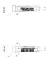
- the state of the barcode label BL1 which is adhered to the sample container T may be as shown in Figs. 9A and 9B .
- a correct sample ID may not be read by the barcode unit B, C, or D.
- Fig. 9A is a diagram showing the state in which on an old barcode label BL1 which is adhered to a sample container T, another new barcode label BL1 is adhered.
- the barcode unit B, C, or D performs barcode reading on this sample container T as described above, a different sample ID may be read. That is, when the reading is executed at a position R1, the correct sample 10 is read from the upper barcode label BL1. However, when the reading is executed at a position R2, the wrong sample ID is read from the lower barcode label BL1.
- Fig. 9B is a diagram showing the state in which a barcode label BL1 which is adhered to a sample container T is slanted.
- the barcodes unit B, C, or D performs barcode reading on this sample container T as described above, a wrong sample ID may be read or the reading may fail. That is, when the reading is executed at a position R3, the correct sample ID is read from the barcode label BL1. However, when the reading is executed at a position R4, the wrong sample ID may be read or the reading may fail due to the cancellation of significant digits occurring in the read result.
- Fig. 10 is a flowchart showing a process of determining the sample ID of a sample container T. Since almost the same process is performed in the barcode units B, C and D, only the processing flowchart related to the barcode unit B will be described hereinafter.
- the CPU 232a of the sample output unit 23 drives the stepping motor B14 and performs an operation of sandwiching a sample container T (S11). That is, the support member B10 is moved forward so that the sample container T is sandwiched between the two rollers B11.
- the CPU 232a when determining a final determination to be described later to be normal by the "reading result determination” process of 314 (S15: YES), the CPU 232a outputs the sample ID obtained by the "reading result determination process of S14 to the subsequent circuit (S16). That is, in this case, the sample ID determined to be normal is transmitted to the transport controller 7.
- the sample ID of the sample container T is re-read. That is, the "barcode reading” process is performed as a retry reading on this sample container T (S18) and the “reading result determination” process is performed on the basis of the reading result obtained in S18 (S19) .
- the CPU 232a when determining that the final determination is determined to be normal by the "reading result determination” process of S19 (S20: YES), the CPU 232a outputs the sample ID obtained by the "reading result determination” process of S19 to the subsequent circuit (transport controller 7) (S16). On the other hand, when determining that the final determination is determined to be wrong (failed) by the "reading result determination” process of S19 (S20: NO), the fact that the reading has failed is output to the subsequent circuit (transport controller 7) (S21).
- the CPU 232a drives the stepping motor B14 and performs an operation of releasing this sample container T (S17). That is, the support member B10 is moved backward so that the rollers B11 are moved backward from the position at which the sample container T is sandwiched between the rollers B11.
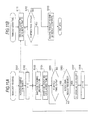
- Fig. 11A is a flowchart showing the "barcode reading” process.
- Fig. 11B is a flowchart showing a "timeout counting" process which is performed concurrently with the "barcode reading” process of Fig. 11A .
- the CPU 232a of the sample output unit 23 rotates the sample container T, which is sandwiched in S11 of Fig. 10 , by driving the stepping motor B25 and thus rotating the roller B21 at a constant rotation speed (S101).
- the sample container T is rotated counterclockwise at a predetermined rotation speed.
- the sample container T is rotated clockwise at half the rotation speed of the general reading.
- the sample container T is smoothly rotated in the retry reading. That is, in the retry reading, since the sample container T is rotated in the reverse direction to the direction in the general reading, the snagging of the barcode label BL1 in the holding section is solved and a possibility of proper reading is increased.
- the CPU 232a starts the "timeout counting" process shown in Fig. 11B and starts counting of an elapsed time T1 (S111).
- the CPU 232a sets a variable n indicating the number of times of obtaining the result to 1 (S102).
- the variable n is stored in the storage section 232b of the sample output unit 23.
- the CPU 232a issues a reading instruction to the barcode reader B31 (S104) and starts the counting of an elapsed time T2 after the issuing of this reading instruction (S104).
- the CPU 232a sets to standby the process until the reading result is received from the barcode reader B31. That is, when the CPU 232a does not receive the reading result (S106: NO), the process returns to S105.
- the CPU 232a receives the reading result (S106)
- the CPU stores this result as the n-th result in the storage section 232b (S107). After that, 1 is added to the value of the variable n (S108) and the process returns to S103.
- the CPU 232a determines that the elapsed time T2 is equal to or longer than the predetermined time Tw (S105: NO)
- the process returns to S103. In this way, the storage of the reading result is repeatedly performed.
- the elapsed time T1 is monitored by the process of Fig. 11B .
- the CPU 232a sets to standby the process.
- the CPU 232a adds the timeout to the end of the reading results which have been stored (S113) and terminates the processes of Figs. 11A and 11B .
- the predetermined time Tout is set to a time which is required to rotate the sample container T once. That is, in the cases of the general reading and the retry reading, when the sample container T is rotated for the predetermined time Tout on the basis of the set rotation speed of the sample container T, the sample container T is rotated once. In addition to the rotation of the sample container T at a constant rotation speed, when the barcode is repeatedly read for a time necessary for the rotation of the sample container T by a predetermined angle (one rotation, in this embodiment), the barcode can be read in the whole range of the rotation angle set in advance.
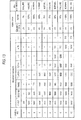
- the reading results stored in S107 and S113 are stored in, for example, the storage section 232b, as shown in the reading result item in Fig. 13 .
- 'AAA', 'BBB' , and 'CCC' indicate sample IDs of the sample containers T in which reading has been performed.
- T/O is a symbol indicating the timeout in S113 of Fig. 11B .
- NG is a symbol indicating that the CPU 232a has received an error from the barcode reader B31 in S106 of Fig. 11A . Such an error is generated when an error is detected by a check digit in the barcode reader B31.
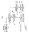
- Fig. 12 is a flowchart showing the "reading result determination” process. In the following number of the reading results, "NG" and “T/O" shown in Fig. 13 are not included.
- the CPU 232a When determining that the number of the reading results related to the sample container T is equal to or less than 1 (S201: YES), the CPU 232a views the determination (hereinafter, referred to as the "final determination") of the reading results of this sample container Task failure (S202) and the process ends. On the other hand, when determining that the number of the reading results related to the sample container T is equal to or greater than 2 (S201: NO), the CPU 232a determines whether or not the number of the reading results is equal to or greater than 2 and equal to or less than 4 (S203).
- the CPU 232a determines whether the sample ID of the first reading result matches the sample ID of the second reading result.
- the final determination is viewed as normal (5205), the matching sample ID is regarded as the sample ID of this sample container T (S206) and the process ends.
- the sample ID of the first reading result does not match the sample ID of the second reading result (S204: NO)
- the final determination is viewed as a failure (S202) and the process ends.
- the CPU 232a determines whether the number of the sample IDs occupying a majority of the reading results is equal to or greater than a predetermined ratio R to the total number of the reading results (S207) When the number of the sample IDs is equal to or greater than the predetermined ratio R (S207: YES), the final determination is viewed as normal (S208), the sample ID occupying the majority is regarded as the sample ID of this sample container T (S209) and the process ends. On the other hand, when the ratio of the sample ID occupying the majority is less than the predetermined ratio R (S207: NO), the CPU 232a views the final determination as a failure (S202) and the process ends.
- the predetermined ratio R which is used in S207 is larger than 50%.
- the final determination related to the Sample Nos. 1 to 10 exemplified in Fig. 13 are shown in the final determination item in Fig. 13 .
- the predetermined ratio R is set to 60%.
- the final determination is viewed as a failure as shown in the Sample Nos. 1 and 2.
- the sample ID of the first reading result matches the sample ID of the second reading result in the Sample Nos. 3 to 5, and thus the final determination is viewed as normal.
- the sample ID of the first reading result does not match the sample ID of the second reading result, and thus the final determination is viewed as a failure.
- the ratio of the sample ID occupying the majority is equal to or greater than 60% in the Sample Nos. 7 and 9, and thus the final determination is viewed as normal.
- the ratio of the sample ID occupying the majority is less than 60% in the Sample Nos. 8 and 10, and thus the final determination is viewed as a failure.
- the reading result is viewed as a failure. Accordingly, it is possible to avoid using a sample ID, which is read only once and of which the reading result may not be correct, as a true value.
- reading the barcode of a sample container T is performed over the whole range during one rotation of the sample container T. Accordingly, a new barcode is necessarily read over a large area regardless of how the barcode label BL1 is adhered to the side surface of the sample container T. Accordingly, the accuracy of the obtained sample ID can be increased.
- the retry reading is performed. Accordingly, even when a proper sample ID is not obtained through the general reading, it can be expected that a proper sample ID is obtained by the retry reading. In addition, during the retry reading, since the sample container T is rotated in the reverse direction, a possibility of obtaining a proper sample ID can be increased as described above.
- blood is exemplified as a measurement target, but urine may also be a measurement target. That is, the invention can also be applied to a sample processing apparatus which examines urine, and further, can also be applied to a clinical sample examination apparatus which examines other clinical samples.
- Tw which is used in the "barcode reading” process of Fig. 11A
- Tout which is used in the "timeout counting” process of Fig. 11B
- the number of the reading results which is used in the determination in S201 and S203 of Fig. 12
- the predetermined ratio R which is used in the determination in S207 of Fig. 12
- the barcode type for example, CODE128, NW-7, ITF, CODE39, JAN and the like
- the barcode unit B may be set by a user.
- the settings of the barcode units B and D are set via the input section 704 of the transport controller 7 and the settings of the barcode unit C are set via the input section 424 of the information processing unit 42.
- these set values are transmitted via the communication sections and are stored in the storage section 232b of the sample output unit 23 and the storage section 502b of the sample transport unit 5, respectively.
- the setting values are stored in the storage section 422b of the information processing unit 42.
- the barcode of a sample container T is read during one rotation of this sample container T, but the invention is not limited thereto.
- the barcode of a sample container T may be read during 3/4 or 1/2 rotation of this sample container T. Accordingly, the unnecessary reading action can be suppressed.
- Fig. 14 schematically shows a ratio of a barcode portion (barcode range) in the barcode label BL1 to the outer circumference of a sample container T and a ratio of a reading range of the barcode reader when the sample container T is viewed from the upper side.
- a ratio of the barcode range is about 50% of the outer circumferential length.
- Fig. 14A is a diagram showing the case in which the barcode reader reading is performed in the range of 75% of the outer circumference when the barcode range is 50% of the outer circumference.
- the remaining range (50%) excluding the barcode range is included in the reading range (75%) of the barcode reader, but at least half the barcode range is always read. Accordingly, when the reading results of this case are subjected to the determination process of Fig. 12 , sample IDs are obtained on the basis of the reading results properly read over the large area, and thus the accuracy of a sample ID which is finally obtained can be increased.
- Fig. 14B is a diagram showing the case in which the barcode reader reading is performed in the range of 50% of the outer circumference when the barcode range is 50% of the outer circumference of a sample container T.
- the reading range (50%) of the barcode reader is the remaining range (50%) excluding the barcode range
- the barcode cannot be read.
- the case in which the reading range of the barcode is outside the barcode range is very rare. Accordingly, even when the barcode reading is performed on a sample container T in this way, in most cases, the barcode reading is performed over a certain amount of range. Therefore, in this case also, a proper sample ID can be obtained with high probability by performing the determination process of Fig. 12 .
- Fig. 14C shows the case in which the barcode reading is performed in the range of 50% of the outer circumference when the barcode range occupies 75% of the outer circumference of a sample container T. In this case, at least 1/3 of the barcode is always read. Accordingly, when the reading results of this case are subjected to the determination process of Fig. 12 , sample IDs are obtained on the basis of the reading results properly read over the large area, and thus the accuracy of a sample ID which is finally obtained can be increased.
- the rotation angle of a rotating sample container may not necessarily correspond to the barcode reading range.
- the reading range with respect to the outer circumference of the sample container T may be manually set. Accordingly, when a ratio of the barcode range to the outer circumference of the sample container T is changed, such as when the diameter of the sample container T is changed, the reading range can be appropriately adjusted so that a sufficient area of the barcode range is read in accordance with the ratio. Therefore, the unnecessary rotation action is suppressed and the barcode can be properly read.
- a sample container T is rotated once in the general reading and the retry reading, but the invention is not limited thereto.
- the rotation angle or a sample container T may be different in the general reading and the retry reading.
- the rotation angle may be 50% of the whole circumference
- the rotation angle may be 75% of the whole circumference. Accordingly, a time required for the general reading can be shortened, and even when the barcode reading is not performed in the general reading, the barcode reading can be securely performed in the retry reading.
- the "reading result determination” process ( Fig. 12 ) according to the above-described embodiment, it is determined whether the number of the reading results is equal to or less than 1 in S201 and it is determined whether the number of the reading results is equal to or less than 4 in S203 when the determination result is NO in S201.
- the invention is not limited thereto and the settings may be appropriately set, respectively.
- the maximum number of the reading results when the determination result is YES in S203 is 4.
- the step S204 can be changed, for example, as follows. That is, when there are units of two or more continuous times of sample IDs in a plurality of sample IDs read,
- the CPU 232a, the CPU 422a, and the CPU 502a determine sample II7s which are true values, respectively.
- the invention is not limited thereto and the determination may be carried out in the barcode units B, C, and D.
- a CPU and a storage section are provided and a sample ID which is a true value is determined by this CPU.
- a sample container T is rotated during the reading of the barcode label BL1.
- a sample container T may be fixed and the barcode readers B31, C31, and D31 may be rotated in the circumferential direction of the sample container T.
- the configuration has been provided in which the barcode reading of the reading section is stopped when a time required to rotate a sample container by a predetermined angle has elapsed, but the invention is not limited to this configuration.
- a configuration may be provided in which an encoder is provided which detects the rotation amount of a sample container and the barcode reading is stopped when the encoder detects that the sample container has been rotated by a predetermined angle.
Landscapes
- Physics & Mathematics (AREA)
- Health & Medical Sciences (AREA)
- Life Sciences & Earth Sciences (AREA)
- Chemical & Material Sciences (AREA)
- Analytical Chemistry (AREA)
- Biochemistry (AREA)
- General Health & Medical Sciences (AREA)
- General Physics & Mathematics (AREA)
- Immunology (AREA)
- Pathology (AREA)
- Automatic Analysis And Handling Materials Therefor (AREA)
Applications Claiming Priority (1)
| Application Number | Priority Date | Filing Date | Title |
|---|---|---|---|
| JP2010048593A JP2011185628A (ja) | 2010-03-05 | 2010-03-05 | 検体分析装置、検体識別情報取得方法および検体識別情報取得装置 |
Publications (3)
| Publication Number | Publication Date |
|---|---|
| EP2363714A2 true EP2363714A2 (de) | 2011-09-07 |
| EP2363714A3 EP2363714A3 (de) | 2015-10-28 |
| EP2363714B1 EP2363714B1 (de) | 2020-12-23 |
Family
ID=44012508
Family Applications (1)
| Application Number | Title | Priority Date | Filing Date |
|---|---|---|---|
| EP11156751.7A Active EP2363714B1 (de) | 2010-03-05 | 2011-03-03 | Probenanalysegerät, Verfahren und Vorrichtung zum Erhalt von Informationen zur Probenidentifikation |
Country Status (4)
| Country | Link |
|---|---|
| US (1) | US8864030B2 (de) |
| EP (1) | EP2363714B1 (de) |
| JP (1) | JP2011185628A (de) |
| CN (1) | CN102192990B (de) |
Cited By (1)
| Publication number | Priority date | Publication date | Assignee | Title |
|---|---|---|---|---|
| WO2021137839A1 (en) * | 2019-12-31 | 2021-07-08 | Gelecek Yazilim Muhendislik Medikal Ve Arastirma Gelistirme Pazarlama Ticaret Limited Sirketi | Barcode scanner for automatic tube sorter |
Families Citing this family (14)
| Publication number | Priority date | Publication date | Assignee | Title |
|---|---|---|---|---|
| US8777107B1 (en) * | 2013-04-25 | 2014-07-15 | Shanghai Shengxiang Science and Technology Co., Ltd. | Wheel type laser encoding device and code reading method |
| JP6294085B2 (ja) * | 2014-01-10 | 2018-03-14 | キヤノンメディカルシステムズ株式会社 | 臨床検査装置 |
| CA2935999C (en) | 2014-01-24 | 2021-11-02 | Siemens Healthcare Diagnostics Inc. | High density in situ barcode reading system |
| JP6585161B2 (ja) * | 2015-03-30 | 2019-10-02 | 株式会社日立ハイテクノロジーズ | 検体搬送装置および検体搬送方法 |
| JP6898252B2 (ja) * | 2015-12-18 | 2021-07-07 | 株式会社堀場製作所 | バーコード位置特定装置およびそのためのコンピュータプログラム |
| JP6850545B2 (ja) * | 2016-03-31 | 2021-03-31 | シスメックス株式会社 | 検体分析システム |
| US10473650B2 (en) | 2017-03-01 | 2019-11-12 | Leadway (Hk) Limited | Reagent mixing and conveying device and reagent mixing method |
| US10112781B2 (en) | 2017-03-01 | 2018-10-30 | Leadway (Hk) Limited | Container autorotation device and container autorotation method |
| US10598637B2 (en) * | 2017-07-18 | 2020-03-24 | Perkinelmer Health Sciences, Inc. | Automated thermal desorption systems configured to determine sample tube orientation and/or cap presence, and related methods |
| EP3540443B1 (de) | 2018-03-16 | 2023-08-30 | Roche Diagnostics GmbH | Laborsystem, laborprobenverteilungssystem und laborautomationssystem |
| US10816516B2 (en) | 2018-03-28 | 2020-10-27 | Perkinelmer Health Sciences, Inc. | Autosamplers and gas chromatographic systems and methods including same |
| JP7490671B2 (ja) * | 2019-12-05 | 2024-05-27 | 株式会社日立ハイテク | 自動分析装置 |
| JP7486342B2 (ja) * | 2020-04-28 | 2024-05-17 | アルテミラ株式会社 | 情報処理システム、情報処理装置、およびプログラム |
| CN115541902A (zh) * | 2021-06-30 | 2022-12-30 | 深圳市瑞图生物技术有限公司 | 旋转扫码机构、方法、装置和样本检测仪 |
Citations (1)
| Publication number | Priority date | Publication date | Assignee | Title |
|---|---|---|---|---|
| JPH0989902A (ja) | 1995-09-21 | 1997-04-04 | Kdk Corp | 血液自動分析装置 |
Family Cites Families (17)
| Publication number | Priority date | Publication date | Assignee | Title |
|---|---|---|---|---|
| US4622457A (en) * | 1981-03-09 | 1986-11-11 | Spectra-Physics, Inc. | Autosampler mechanism |
| ES8401636A1 (es) * | 1981-07-20 | 1983-12-16 | American Hospital Supply Corp | Dispositivo de carga y transferencia para presentar a un analizador quimico recipientes de muestras de fluidos corporales y para retirarlos y alimentarlos seguidamente. |
| JPS60104955A (ja) | 1983-11-11 | 1985-06-10 | Hitachi Koki Co Ltd | 電子写真像形成部材 |
| JPS60104955U (ja) * | 1983-12-20 | 1985-07-17 | トキコ株式会社 | 容器バ−コ−ド読取装置 |
| JPH0423073A (ja) * | 1990-05-17 | 1992-01-27 | Canon Inc | 画像処理装置 |
| JPH0736284Y2 (ja) * | 1990-10-05 | 1995-08-16 | 東亜医用電子株式会社 | 検体容器の検体識別コード読取装置 |
| US5350564A (en) * | 1993-06-28 | 1994-09-27 | Baxter Diagnostics Inc. | Automated chemical analyzer with apparatus and method for conveying and temporary storage of sample tubes |
| JP3347407B2 (ja) * | 1993-08-17 | 2002-11-20 | シスメックス株式会社 | 試料容器回転装置 |
| AUPP058197A0 (en) * | 1997-11-27 | 1997-12-18 | A.I. Scientific Pty Ltd | Pathology sample tube distributor |
| JP2000251011A (ja) * | 1999-03-01 | 2000-09-14 | Toshiba Corp | バーコード認識装置および帳票認識装置 |
| JP3780229B2 (ja) | 2002-06-28 | 2006-05-31 | アロカ株式会社 | 検体分析装置 |
| JP3759091B2 (ja) * | 2002-09-26 | 2006-03-22 | ブラザー工業株式会社 | ミシン |
| JP4071641B2 (ja) | 2003-01-17 | 2008-04-02 | シスメックス株式会社 | 試料検査システム |
| JP3908744B2 (ja) * | 2004-03-08 | 2007-04-25 | 株式会社アイディエス | 試験管のバーコード読取り装置 |
| JP4098272B2 (ja) * | 2004-04-26 | 2008-06-11 | 株式会社アイディエス | 試験管のバーコード読取り装置 |
| US7964413B2 (en) * | 2005-03-10 | 2011-06-21 | Gen-Probe Incorporated | Method for continuous mode processing of multiple reaction receptacles in a real-time amplification assay |
| US20090028754A1 (en) * | 2007-07-27 | 2009-01-29 | Dade Behring Inc. | Insert for Restraining Tube Rotation in a Sample Tube Rack |
-
2010
- 2010-03-05 JP JP2010048593A patent/JP2011185628A/ja active Pending
-
2011
- 2011-01-26 CN CN201110027616.4A patent/CN102192990B/zh not_active Expired - Fee Related
- 2011-03-03 EP EP11156751.7A patent/EP2363714B1/de active Active
- 2011-03-03 US US13/039,977 patent/US8864030B2/en active Active
Patent Citations (1)
| Publication number | Priority date | Publication date | Assignee | Title |
|---|---|---|---|---|
| JPH0989902A (ja) | 1995-09-21 | 1997-04-04 | Kdk Corp | 血液自動分析装置 |
Cited By (1)
| Publication number | Priority date | Publication date | Assignee | Title |
|---|---|---|---|---|
| WO2021137839A1 (en) * | 2019-12-31 | 2021-07-08 | Gelecek Yazilim Muhendislik Medikal Ve Arastirma Gelistirme Pazarlama Ticaret Limited Sirketi | Barcode scanner for automatic tube sorter |
Also Published As
| Publication number | Publication date |
|---|---|
| US20110215149A1 (en) | 2011-09-08 |
| CN102192990A (zh) | 2011-09-21 |
| JP2011185628A (ja) | 2011-09-22 |
| EP2363714A3 (de) | 2015-10-28 |
| US8864030B2 (en) | 2014-10-21 |
| CN102192990B (zh) | 2015-12-16 |
| EP2363714B1 (de) | 2020-12-23 |
Similar Documents
| Publication | Publication Date | Title |
|---|---|---|
| EP2363714A2 (de) | Probenanalysegerät, Verfahren und Vorrichtung zum Erhalt von Informationen zur Probenidentifikation | |
| US9417253B2 (en) | Specimen processing system and specimen container classifying apparatus | |
| US8920724B2 (en) | Specimen processing apparatus | |
| JP5339853B2 (ja) | 検体処理システム | |
| US8329101B2 (en) | Sample analyzer | |
| US9316583B2 (en) | Specimen analyzing method and specimen analyzing apparatus | |
| EP2605020B1 (de) | Verfahren zur Probenanalyse und Probenanalysator | |
| US8143065B2 (en) | Specimen processing device, specimen conveyance device, and specimen conveyance method | |
| JP5198094B2 (ja) | 分析装置 | |
| CN103460055B (zh) | 样本分析系统及样本分析装置 | |
| CN103033633B (zh) | 试样分析装置以及试样分析装置的控制方法 | |
| US9201083B2 (en) | Sample analyzer and reagent management method | |
| JP5485766B2 (ja) | 検体ラック搬送システム | |
| EP2831595A1 (de) | Systeme und verfahren zur erkennung umgefallener behälter für eine vorrichtung zur automatisierten beurteilung des wachstums von mikroorganismen in testproben | |
| AU2013239965A1 (en) | Systems and methods for detecting fallen containers suitable for apparatus for automated evaluation of microorganism growth in test samples | |
| JP2011075445A (ja) | ラック回収ユニット | |
| JP2008249721A (ja) | 試料収容容器に対する自動マーキング方法。 | |
| JP5171352B2 (ja) | 免疫分析装置及び免疫分析方法 | |
| JP5336555B2 (ja) | 検体分析装置 | |
| JP2008309661A (ja) | 分析装置 | |
| JP5484107B2 (ja) | 検体処理システム | |
| JP2015028492A (ja) | 尿分析装置および尿分析方法 | |
| JP2012132932A (ja) | 血液分析装置および血液分析システム | |
| JP5651721B2 (ja) | 分析装置および検体測定方法 | |
| CN221209044U (zh) | 试管分拣设备的分拣机构 |
Legal Events
| Date | Code | Title | Description |
|---|---|---|---|
| PUAI | Public reference made under article 153(3) epc to a published international application that has entered the european phase |
Free format text: ORIGINAL CODE: 0009012 |
|
| AK | Designated contracting states |
Kind code of ref document: A2 Designated state(s): AL AT BE BG CH CY CZ DE DK EE ES FI FR GB GR HR HU IE IS IT LI LT LU LV MC MK MT NL NO PL PT RO RS SE SI SK SM TR |
|
| AX | Request for extension of the european patent |
Extension state: BA ME |
|
| PUAL | Search report despatched |
Free format text: ORIGINAL CODE: 0009013 |
|
| AK | Designated contracting states |
Kind code of ref document: A3 Designated state(s): AL AT BE BG CH CY CZ DE DK EE ES FI FR GB GR HR HU IE IS IT LI LT LU LV MC MK MT NL NO PL PT RO RS SE SI SK SM TR |
|
| AX | Request for extension of the european patent |
Extension state: BA ME |
|
| RIC1 | Information provided on ipc code assigned before grant |
Ipc: G01N 35/00 20060101AFI20150922BHEP |
|
| 17P | Request for examination filed |
Effective date: 20160324 |
|
| RBV | Designated contracting states (corrected) |
Designated state(s): AL AT BE BG CH CY CZ DE DK EE ES FI FR GB GR HR HU IE IS IT LI LT LU LV MC MK MT NL NO PL PT RO RS SE SI SK SM TR |
|
| GRAP | Despatch of communication of intention to grant a patent |
Free format text: ORIGINAL CODE: EPIDOSNIGR1 |
|
| STAA | Information on the status of an ep patent application or granted ep patent |
Free format text: STATUS: GRANT OF PATENT IS INTENDED |
|
| INTG | Intention to grant announced |
Effective date: 20200721 |
|
| GRAS | Grant fee paid |
Free format text: ORIGINAL CODE: EPIDOSNIGR3 |
|
| GRAA | (expected) grant |
Free format text: ORIGINAL CODE: 0009210 |
|
| STAA | Information on the status of an ep patent application or granted ep patent |
Free format text: STATUS: THE PATENT HAS BEEN GRANTED |
|
| AK | Designated contracting states |
Kind code of ref document: B1 Designated state(s): AL AT BE BG CH CY CZ DE DK EE ES FI FR GB GR HR HU IE IS IT LI LT LU LV MC MK MT NL NO PL PT RO RS SE SI SK SM TR |
|
| REG | Reference to a national code |
Ref country code: GB Ref legal event code: FG4D |
|
| REG | Reference to a national code |
Ref country code: DE Ref legal event code: R096 Ref document number: 602011069708 Country of ref document: DE |
|
| REG | Reference to a national code |
Ref country code: AT Ref legal event code: REF Ref document number: 1348239 Country of ref document: AT Kind code of ref document: T Effective date: 20210115 |
|
| REG | Reference to a national code |
Ref country code: IE Ref legal event code: FG4D |
|
| PG25 | Lapsed in a contracting state [announced via postgrant information from national office to epo] |
Ref country code: GR Free format text: LAPSE BECAUSE OF FAILURE TO SUBMIT A TRANSLATION OF THE DESCRIPTION OR TO PAY THE FEE WITHIN THE PRESCRIBED TIME-LIMIT Effective date: 20210324 Ref country code: RS Free format text: LAPSE BECAUSE OF FAILURE TO SUBMIT A TRANSLATION OF THE DESCRIPTION OR TO PAY THE FEE WITHIN THE PRESCRIBED TIME-LIMIT Effective date: 20201223 Ref country code: FI Free format text: LAPSE BECAUSE OF FAILURE TO SUBMIT A TRANSLATION OF THE DESCRIPTION OR TO PAY THE FEE WITHIN THE PRESCRIBED TIME-LIMIT Effective date: 20201223 Ref country code: NO Free format text: LAPSE BECAUSE OF FAILURE TO SUBMIT A TRANSLATION OF THE DESCRIPTION OR TO PAY THE FEE WITHIN THE PRESCRIBED TIME-LIMIT Effective date: 20210323 |
|
| REG | Reference to a national code |
Ref country code: AT Ref legal event code: MK05 Ref document number: 1348239 Country of ref document: AT Kind code of ref document: T Effective date: 20201223 |
|
| REG | Reference to a national code |
Ref country code: NL Ref legal event code: MP Effective date: 20201223 |
|
| PG25 | Lapsed in a contracting state [announced via postgrant information from national office to epo] |
Ref country code: SE Free format text: LAPSE BECAUSE OF FAILURE TO SUBMIT A TRANSLATION OF THE DESCRIPTION OR TO PAY THE FEE WITHIN THE PRESCRIBED TIME-LIMIT Effective date: 20201223 Ref country code: LV Free format text: LAPSE BECAUSE OF FAILURE TO SUBMIT A TRANSLATION OF THE DESCRIPTION OR TO PAY THE FEE WITHIN THE PRESCRIBED TIME-LIMIT Effective date: 20201223 Ref country code: BG Free format text: LAPSE BECAUSE OF FAILURE TO SUBMIT A TRANSLATION OF THE DESCRIPTION OR TO PAY THE FEE WITHIN THE PRESCRIBED TIME-LIMIT Effective date: 20210323 |
|
| PG25 | Lapsed in a contracting state [announced via postgrant information from national office to epo] |
Ref country code: NL Free format text: LAPSE BECAUSE OF FAILURE TO SUBMIT A TRANSLATION OF THE DESCRIPTION OR TO PAY THE FEE WITHIN THE PRESCRIBED TIME-LIMIT Effective date: 20201223 Ref country code: HR Free format text: LAPSE BECAUSE OF FAILURE TO SUBMIT A TRANSLATION OF THE DESCRIPTION OR TO PAY THE FEE WITHIN THE PRESCRIBED TIME-LIMIT Effective date: 20201223 |
|
| REG | Reference to a national code |
Ref country code: LT Ref legal event code: MG9D |
|
| PG25 | Lapsed in a contracting state [announced via postgrant information from national office to epo] |
Ref country code: LT Free format text: LAPSE BECAUSE OF FAILURE TO SUBMIT A TRANSLATION OF THE DESCRIPTION OR TO PAY THE FEE WITHIN THE PRESCRIBED TIME-LIMIT Effective date: 20201223 Ref country code: EE Free format text: LAPSE BECAUSE OF FAILURE TO SUBMIT A TRANSLATION OF THE DESCRIPTION OR TO PAY THE FEE WITHIN THE PRESCRIBED TIME-LIMIT Effective date: 20201223 Ref country code: CZ Free format text: LAPSE BECAUSE OF FAILURE TO SUBMIT A TRANSLATION OF THE DESCRIPTION OR TO PAY THE FEE WITHIN THE PRESCRIBED TIME-LIMIT Effective date: 20201223 Ref country code: RO Free format text: LAPSE BECAUSE OF FAILURE TO SUBMIT A TRANSLATION OF THE DESCRIPTION OR TO PAY THE FEE WITHIN THE PRESCRIBED TIME-LIMIT Effective date: 20201223 Ref country code: SK Free format text: LAPSE BECAUSE OF FAILURE TO SUBMIT A TRANSLATION OF THE DESCRIPTION OR TO PAY THE FEE WITHIN THE PRESCRIBED TIME-LIMIT Effective date: 20201223 Ref country code: PT Free format text: LAPSE BECAUSE OF FAILURE TO SUBMIT A TRANSLATION OF THE DESCRIPTION OR TO PAY THE FEE WITHIN THE PRESCRIBED TIME-LIMIT Effective date: 20210423 Ref country code: SM Free format text: LAPSE BECAUSE OF FAILURE TO SUBMIT A TRANSLATION OF THE DESCRIPTION OR TO PAY THE FEE WITHIN THE PRESCRIBED TIME-LIMIT Effective date: 20201223 |
|
| PG25 | Lapsed in a contracting state [announced via postgrant information from national office to epo] |
Ref country code: PL Free format text: LAPSE BECAUSE OF FAILURE TO SUBMIT A TRANSLATION OF THE DESCRIPTION OR TO PAY THE FEE WITHIN THE PRESCRIBED TIME-LIMIT Effective date: 20201223 Ref country code: AT Free format text: LAPSE BECAUSE OF FAILURE TO SUBMIT A TRANSLATION OF THE DESCRIPTION OR TO PAY THE FEE WITHIN THE PRESCRIBED TIME-LIMIT Effective date: 20201223 |
|
| REG | Reference to a national code |
Ref country code: DE Ref legal event code: R097 Ref document number: 602011069708 Country of ref document: DE |
|
| PG25 | Lapsed in a contracting state [announced via postgrant information from national office to epo] |
Ref country code: IS Free format text: LAPSE BECAUSE OF FAILURE TO SUBMIT A TRANSLATION OF THE DESCRIPTION OR TO PAY THE FEE WITHIN THE PRESCRIBED TIME-LIMIT Effective date: 20210423 |
|
| PG25 | Lapsed in a contracting state [announced via postgrant information from national office to epo] |
Ref country code: MC Free format text: LAPSE BECAUSE OF FAILURE TO SUBMIT A TRANSLATION OF THE DESCRIPTION OR TO PAY THE FEE WITHIN THE PRESCRIBED TIME-LIMIT Effective date: 20201223 Ref country code: AL Free format text: LAPSE BECAUSE OF FAILURE TO SUBMIT A TRANSLATION OF THE DESCRIPTION OR TO PAY THE FEE WITHIN THE PRESCRIBED TIME-LIMIT Effective date: 20201223 Ref country code: IT Free format text: LAPSE BECAUSE OF FAILURE TO SUBMIT A TRANSLATION OF THE DESCRIPTION OR TO PAY THE FEE WITHIN THE PRESCRIBED TIME-LIMIT Effective date: 20201223 |
|
| PLBE | No opposition filed within time limit |
Free format text: ORIGINAL CODE: 0009261 |
|
| REG | Reference to a national code |
Ref country code: CH Ref legal event code: PL |
|
| STAA | Information on the status of an ep patent application or granted ep patent |
Free format text: STATUS: NO OPPOSITION FILED WITHIN TIME LIMIT |
|
| PG25 | Lapsed in a contracting state [announced via postgrant information from national office to epo] |
Ref country code: DK Free format text: LAPSE BECAUSE OF FAILURE TO SUBMIT A TRANSLATION OF THE DESCRIPTION OR TO PAY THE FEE WITHIN THE PRESCRIBED TIME-LIMIT Effective date: 20201223 Ref country code: ES Free format text: LAPSE BECAUSE OF FAILURE TO SUBMIT A TRANSLATION OF THE DESCRIPTION OR TO PAY THE FEE WITHIN THE PRESCRIBED TIME-LIMIT Effective date: 20201223 |
|
| 26N | No opposition filed |
Effective date: 20210924 |
|
| REG | Reference to a national code |
Ref country code: BE Ref legal event code: MM Effective date: 20210331 |
|
| PG25 | Lapsed in a contracting state [announced via postgrant information from national office to epo] |
Ref country code: IE Free format text: LAPSE BECAUSE OF NON-PAYMENT OF DUE FEES Effective date: 20210303 Ref country code: LU Free format text: LAPSE BECAUSE OF NON-PAYMENT OF DUE FEES Effective date: 20210303 Ref country code: LI Free format text: LAPSE BECAUSE OF NON-PAYMENT OF DUE FEES Effective date: 20210331 Ref country code: CH Free format text: LAPSE BECAUSE OF NON-PAYMENT OF DUE FEES Effective date: 20210331 |
|
| PG25 | Lapsed in a contracting state [announced via postgrant information from national office to epo] |
Ref country code: SI Free format text: LAPSE BECAUSE OF FAILURE TO SUBMIT A TRANSLATION OF THE DESCRIPTION OR TO PAY THE FEE WITHIN THE PRESCRIBED TIME-LIMIT Effective date: 20201223 |
|
| PG25 | Lapsed in a contracting state [announced via postgrant information from national office to epo] |
Ref country code: IS Free format text: LAPSE BECAUSE OF FAILURE TO SUBMIT A TRANSLATION OF THE DESCRIPTION OR TO PAY THE FEE WITHIN THE PRESCRIBED TIME-LIMIT Effective date: 20210423 |
|
| PG25 | Lapsed in a contracting state [announced via postgrant information from national office to epo] |
Ref country code: BE Free format text: LAPSE BECAUSE OF NON-PAYMENT OF DUE FEES Effective date: 20210331 |
|
| PG25 | Lapsed in a contracting state [announced via postgrant information from national office to epo] |
Ref country code: HU Free format text: LAPSE BECAUSE OF FAILURE TO SUBMIT A TRANSLATION OF THE DESCRIPTION OR TO PAY THE FEE WITHIN THE PRESCRIBED TIME-LIMIT; INVALID AB INITIO Effective date: 20110303 Ref country code: CY Free format text: LAPSE BECAUSE OF FAILURE TO SUBMIT A TRANSLATION OF THE DESCRIPTION OR TO PAY THE FEE WITHIN THE PRESCRIBED TIME-LIMIT Effective date: 20201223 |
|
| PG25 | Lapsed in a contracting state [announced via postgrant information from national office to epo] |
Ref country code: MK Free format text: LAPSE BECAUSE OF FAILURE TO SUBMIT A TRANSLATION OF THE DESCRIPTION OR TO PAY THE FEE WITHIN THE PRESCRIBED TIME-LIMIT Effective date: 20201223 |
|
| PGFP | Annual fee paid to national office [announced via postgrant information from national office to epo] |
Ref country code: DE Payment date: 20240130 Year of fee payment: 14 |
|
| PGFP | Annual fee paid to national office [announced via postgrant information from national office to epo] |
Ref country code: FR Payment date: 20240213 Year of fee payment: 14 |
|
| PG25 | Lapsed in a contracting state [announced via postgrant information from national office to epo] |
Ref country code: MT Free format text: LAPSE BECAUSE OF FAILURE TO SUBMIT A TRANSLATION OF THE DESCRIPTION OR TO PAY THE FEE WITHIN THE PRESCRIBED TIME-LIMIT Effective date: 20201223 |
|
| REG | Reference to a national code |
Ref country code: DE Ref legal event code: R119 Ref document number: 602011069708 Country of ref document: DE |
|
| PG25 | Lapsed in a contracting state [announced via postgrant information from national office to epo] |
Ref country code: TR Free format text: LAPSE BECAUSE OF FAILURE TO SUBMIT A TRANSLATION OF THE DESCRIPTION OR TO PAY THE FEE WITHIN THE PRESCRIBED TIME-LIMIT Effective date: 20201223 |
|
| PG25 | Lapsed in a contracting state [announced via postgrant information from national office to epo] |
Ref country code: DE Free format text: LAPSE BECAUSE OF NON-PAYMENT OF DUE FEES Effective date: 20251001 |
|
| PG25 | Lapsed in a contracting state [announced via postgrant information from national office to epo] |
Ref country code: FR Free format text: LAPSE BECAUSE OF NON-PAYMENT OF DUE FEES Effective date: 20250331 |
|
| PGFP | Annual fee paid to national office [announced via postgrant information from national office to epo] |
Ref country code: GB Payment date: 20260202 Year of fee payment: 16 |