EP2364882A1 - Anordnung zum elektrischen Verbinden von zwei elektrischen Kontaktstellen - Google Patents
Anordnung zum elektrischen Verbinden von zwei elektrischen Kontaktstellen Download PDFInfo
- Publication number
- EP2364882A1 EP2364882A1 EP10305241A EP10305241A EP2364882A1 EP 2364882 A1 EP2364882 A1 EP 2364882A1 EP 10305241 A EP10305241 A EP 10305241A EP 10305241 A EP10305241 A EP 10305241A EP 2364882 A1 EP2364882 A1 EP 2364882A1
- Authority
- EP
- European Patent Office
- Prior art keywords
- steering shaft
- motor vehicle
- arrangement according
- strand
- contact point
- Prior art date
- Legal status (The legal status is an assumption and is not a legal conclusion. Google has not performed a legal analysis and makes no representation as to the accuracy of the status listed.)
- Granted
Links
Images

Classifications
-
- B—PERFORMING OPERATIONS; TRANSPORTING
- B60—VEHICLES IN GENERAL
- B60R—VEHICLES, VEHICLE FITTINGS, OR VEHICLE PARTS, NOT OTHERWISE PROVIDED FOR
- B60R16/00—Electric or fluid circuits specially adapted for vehicles and not otherwise provided for; Arrangement of elements of electric or fluid circuits specially adapted for vehicles and not otherwise provided for
- B60R16/02—Electric or fluid circuits specially adapted for vehicles and not otherwise provided for; Arrangement of elements of electric or fluid circuits specially adapted for vehicles and not otherwise provided for electric constitutive elements
- B60R16/023—Electric or fluid circuits specially adapted for vehicles and not otherwise provided for; Arrangement of elements of electric or fluid circuits specially adapted for vehicles and not otherwise provided for electric constitutive elements for transmission of signals between vehicle parts or subsystems
- B60R16/027—Electric or fluid circuits specially adapted for vehicles and not otherwise provided for; Arrangement of elements of electric or fluid circuits specially adapted for vehicles and not otherwise provided for electric constitutive elements for transmission of signals between vehicle parts or subsystems between relatively movable parts of the vehicle, e.g. between steering wheel and column
Definitions
- the invention relates to an arrangement for electrically connecting two electrical contact points, which are located in a motor vehicle, of which a first contact point is attached to a rotatable component of the motor vehicle, while a second contact point is fixedly mounted on parts of the motor vehicle, and which are connected to one another by an electrical line arranged in a hollow steering shaft of the motor vehicle, in which the first contact point is arranged in the region of a steering wheel of the motor vehicle connected to the steering shaft, while the second contact point is in the region of the end of the steering shaft remote from the steering wheel ( DE 199 00 083 A1 ).
- Such an arrangement is needed for example for electrically connecting functional elements which are mounted in or on the steering wheel of a motor vehicle.
- Such functional elements are, for example, switches for speakers and a telephone system and for turn signals, windscreen wipers and a horn.
- the trigger mechanism for an airbag is usually mounted on the steering wheel.
- the electrical connection of such an arrangement is carried out in current technology throughout, without sliding electrical contacts. It is used in known technique a running in turns ribbon cable, which can follow the rotation of the steering wheel by changing the position of their turns.
- an arrangement for power transmission has become known by means of a type of a barrel of a clock wound into a wound body FBL.
- the wound-up FBL "breathes" like the spring of a clock.
- the turns of the wound FBL are contracted in one direction of rotation to a smaller diameter. You go back in the other direction to a larger diameter.
- From the EP 0 735 631 B1 shows another arrangement for power transmission, in which the ribbon cable located in a cassette is divided into two partial windings with opposite sense of winding and a U-shaped reversal point, between which an annular guide body is arranged.
- the reversal point between the partial windings engages in the guide body, which is taken along by a rotating movement of a steering wheel, in which the arrangement is mounted, from the moving part windings in the circumferential direction of the cassette.
- the guide body serves to guide and mutual support of the partial windings. He slides on actuation of the arrangement on a correspondingly trained bottom of the cassette.
- the invention has for its object to make the initially described arrangement so that their reliability is increased.
- a mechanically stable strand is attached, which extends over the entire length and is separated by a circumferential free space of the same, and around which at least one flat-conductor ribbon cable with a gap between the turns is wound around as the electric wire.
- the flat conductor strip line - hereinafter referred to as "FL-BL" - is loaded only insignificantly mechanically in this arrangement in the operation of a motor vehicle. Damage to the FL-BL and the two contact points can therefore be ruled out under normal or proper handling.
- the turns of the FL-BL are widened in one direction of rotation upon rotation of the steering wheel, the FL-BL being slightly moved in the radial direction away from the strand around which it is wound. In the other direction of rotation of the steering wheel, the FL-BL stretches closer to the strand.
- These movements of the FL-BL are taken into account in their installation in the steering shaft with a kind of zero position, from which the turns of the same not only rise to a larger diameter, but can also narrow easily in the direction of the strand.
- the steering wheel executes, for example, two revolutions in both directions of rotation, so that the movements of the windings of the FL-BL are very small in both directions described.
- the FL-BL may preferably be arranged at a distance from the same existing an insulating tube, which rests on the inside of the steering shaft.
- the tube may advantageously be coated on its FL-BL facing side with sound absorbing material.
- the strand which may be designed as a rod or tube, may also be preferably coated on its outer surface with sound-absorbing material.
- Fig. 1 is a hollow, consisting of metal steering shaft 1 of a motor vehicle shown in section, at the first end of a steering wheel 2 is mounted.
- the second end of the steering shaft 1 is connected in the position of use with a sake of simplicity not shown steering mechanism of the motor vehicle.
- a first electrical contact point 3 rotatable together with the same about the axis of the steering shaft 1 is mounted.
- a second electrical contact point 4 is mounted, on fixed parts of the motor vehicle.
- Both contact points 3 and 4 are characterized by an in Fig. 1 only indicated electrical line 5 connected together. Their actual form and arrangement go out of the ones in the Fig. 2 and 5 illustrated embodiments.
- an elongate strand 6 Arranged centrally in the steering shaft 1 is an elongate strand 6, which is mechanically stable and separated from the steering shaft 1 by a circumferential free space. It may be made in one piece or even telescopically and is advantageously made of plastic, such as polybutylene terephthalate (PBT), polycarbonate (PC) or polyoxymethylene (PCM).
- the strand 6 may also consist of metal. He preferably has a circular cross-section. It could also be oval or polygon.
- the strand 6 may be a solid rod or a tube. It is advantageously mechanically coupled to the steering shaft 1 and the steering wheel 2, so that it is rotated together with the steering shaft 1 upon rotation of the steering wheel 2.
- FL-BL 7 At least one flat conductor ribbon cable 7 - hereinafter referred to as "FL-BL 7" - wrapped around the strand 6, with gaps between their turns or with a long stroke.
- the pitch of the FL-BL 7 is, for example, at a width thereof between 10 mm and 18 mm at 12 mm to 30 mm.
- the FL-BL 7 must always be designed and wound so that a gap between their turns remains.
- the width of the gap between the turns of an FL-BL 7 is 10 mm when the FL-BL has a width of 15 mm and the pitch is 25 mm.
- the FL-BL 7 has a number of flat electrical conductors that are parallel and spaced are embedded in each other in insulating material.
- the electrical conductors of the FL-BL 7, which are preferably made of copper, are electrically connected in mounted arrangement with the electrical contacts of the contact points 3 and 4.
- the FL-BL 7 In the installed state, ie in the rest position or a zero position, the FL-BL 7 is loosely wrapped around the strand 6, so that their turns narrow at a corresponding rotation of the steering wheel 2 and can invest in the strand 6.
- the number of turns of the FL-BL 7 is relatively low due to the long stroke, with which it is wound around the strand 6, so that upon rotation of the steering wheel 2, in which the FL-BL 7 via the contact point 3 at its taken there end, their radial movement in both directions - from the strand 6 away and on the strand 6 to - is relatively low. It can already be ruled out with some certainty that the FL-BL 7 hits the steering shaft 1 during operation of the motor vehicle with corresponding noise development.
- an existing elastic insulating material pipe 8 is mounted in the steering shaft 1 with advantage, which rests on the inside of the steering shaft 1.
- the tube 8 may also be made of metal.
- a layer 9 made of a sound absorbing material may additionally be applied.
- a layer 10 of a sound absorbing material may be applied on the outer surface of the strand 6 preferably be applied a layer 10 of a sound absorbing material.
- sound-insulating material for example, polyester fibers can be used.
- the tube 8 When mounting the assembly in the hollow steering shaft 1, the tube 8 is advantageously mounted first.
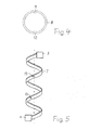
- the existing of elastic material tube 8 has according to Fig. 4 at least two diametrically opposed groove-like indentations 11 and 12 which extend over its entire length. It can thereby be compressed to reduced radial dimensions and relatively easily inserted into the steering shaft 1.
- the tube 8 lays down finally due to its elasticity to the inner wall of the steering shaft 1.
- At least one FL-BL 7 is wound around the strand 6.
- two or more FL-BLEN 7 can be used. They are expediently combined to form a one-piece structure and can according to Fig. 5 in their course at points 13, which have a sufficient distance from each other, are selectively mechanically fixed together.
- the connection can be made for example by gluing, welding, riveting or clasping. If more than two FL-BLen 7 are used, two FL-Blen 7 can also be selectively connected at mutually offset points.
Landscapes
- Engineering & Computer Science (AREA)
- Mechanical Engineering (AREA)
- Steering Controls (AREA)
Abstract
Description
- Die Erfindung bezieht sich auf eine Anordnung zum elektrischen Verbinden von zwei elektrischen Kontaktstellen, die sich in einem Kraftfahrzeug befinden, von denen eine erste Kontaktstelle an einem drehbaren Bauteil des Kraftfahrzeugs angebracht ist, während eine zweite Kontaktstelle feststehenden an Teilen des Kraftfahrzeugs montiert ist, und welche durch eine in einer hohlen Lenkwelle des Kraftfahrzeugs angeordneten elektrischen Leitung miteinander verbunden sind, bei welcher die erste Kontaktstelle im Bereich eines mit der Lenkwelle verbundenen Lenkrades des Kraftfahrzeugs angeordnet ist, während die zweite Kontaktstelle sich im Bereich des vom Lenkrad entfernten Endes der Lenkwelle befindet (
DE 199 00 083 A1 ). - Eine solche Anordnung wird beispielsweise zum elektrischen Verbinden von Funktionselementen benötigt, die im oder am Lenkrad eines Kraftfahrzeugs angebracht sind. Solche Funktionselemente sind beispielsweise Schalter für Lautsprecher und eine Telefonanlage sowie für Blinker, Scheibenwischer und eine Hupe. Auch der Auslösemechanismus für einen Airbag ist in der Regel am Lenkrad angebracht. Die elektrische Verbindung einer derartigen Anordnung ist in heutiger Technik durchgehend, ohne schleifende elektrische Kontakte ausgeführt. Es wird in bekannter Technik eine in Windungen verlaufende Flachband-Leitung eingesetzt, welche der Drehbewegung des Lenkrades durch Änderung der Lage ihrer Windungen folgen kann.
- Durch die
EP 0 417 350 A1 ist beispielsweise eine Anordnung zur Stromübertragung mittels einer nach Art eines Federhauses einer Uhr zu einem Wickelkörper gewickelten FBL bekanntgeworden. Bei einer relativen Drehbewegung der beiden durch die FBL verbundenen Kontaktstellen, "atmet" die aufgewickelte FBL wie die Feder einer Uhr. Die Windungen der gewickelten FBL werden in der einen Drehrichtung auf einen kleineren Durchmesser zusammengezogen. Sie gehen in der anderen Drehrichtung wieder auf einen größeren Durchmesser auf. - Aus der
EP 0 735 631 B1 geht eine andere Anordnung zur Stromübertragung hervor, bei welcher die in einer Kassette befindliche Flachband-Leitung in zwei Teilwicklungen mit gegenläufigem Wickelsinn und einer U-förmigen Umkehrstelle aufgeteilt ist, zwischen denen ein ringförmiger Führungskörper angeordnet ist. Die Umkehrstelle zwischen den Teilwicklungen greift in den Führungskörper ein, der bei einer Drehbewegung eines Lenkrades, in welchem die Anordnung angebracht ist, von den sich bewegenden Teilwicklungen in Umfangsrichtung der Kassette mitgenommen wird. Der Führungskörper dient zur Führung und zur gegenseitigen Abstützung der Teilwicklungen. Er gleitet bei Betätigung der Anordnung auf einem entsprechend ausgebildeten Boden der Kassette. - Bei der bekannten Anordnung nach der eingangs erwähnten
DE 199 00 083 A1 ist in der hohlen Lenkwelle eines Kraftfahrzeugs eine elektrische Leitung mit geradlinigem Verlauf angebracht, die an einem Ende mit einer ersten, im Bereich des mit der Lenkwelle verbundenen Lenkrades angebrachten Kontaktstelle und an ihrem anderen Ende mit einer zweiten, an dem dem Lenkrad abgewandten Ende der Lenkwelle verbunden ist. Die Leitung besteht aus flexiblem Material und ihre Länge ist so groß, daß ihre Verformung im Drehbereich des Lenkrades ausschließlich elastisch erfolgt. Bei einer Drehung des Lenkrades wird die Leitung um ihre Achse tordiert, so daß trotz der geschilderten Ausführung derselben eine Beschädigung insbesondere an den Kontaktstellen nicht ausgeschlossen werden kann. - Der Erfindung liegt die Aufgabe zugrunde, die eingangs geschilderte Anordnung so zu gestalten, daß ihre Funktionssicherheit erhöht ist.
- Diese Aufgabe wird gemäß der Erfindung dadurch gelöst, daß zentrisch in der Lenkwelle ein mechanisch stabiler Strang angebracht ist, der sich über deren ganze Länge erstreckt und durch einen umlaufenden Freiraum von derselben getrennt ist, und um welchen als elektrische Leitung mindestens eine Flachleiter-Bandleitung mit Lücke zwischen den Windungen herumgewickelt ist.
- Die Flachleiter-Bandleitung - im folgenden kurz "FL-BL" genannt - wird bei dieser Anordnung im Betrieb eines Kraftfahrzeugs nur unwesentlich mechanisch belastet. Eine Beschädigung der FL-BL und auch der beiden Kontaktstellen kann daher bei normaler bzw. sachgerechter Handhabung ausgeschlossen werden. Die Windungen der FL-BL werden bei einer Drehung des Lenkrades in der einen Drehrichtung aufgeweitet, wobei die FL-BL geringfügig in radialer Richtung vom Strang wegbewegt wird, um den sie herumgewickelt ist. In der anderen Drehrichtung des Lenkrades legt die FL-BL sich enger an den Strang an. Diese Bewegungen der FL-BL werden bei ihrem Einbau in die Lenkwelle mit einer Art Nullstellung berücksichtigt, aus der heraus die Windungen derselben nicht nur auf einen größeren Durchmesser aufgehen, sondern sich auch problemlos in Richtung des Stranges verengen können. Dabei ist zu berücksichtigen, daß das Lenkrad in beiden Drehrichtungen beispielsweise zwei Umdrehungen ausführt, so daß die Bewegungen der Windungen der FL-BL in beiden beschriebenen Richtungen sehr klein sind.
- Um die FL-BL herum kann vorzugsweise mit Abstand zu derselben ein aus Isoliermaterial bestehendes Rohr angeordnet sein, das innen an der Lenkwelle anliegt. Das Rohr kann mit Vorteil auf seiner der FL-BL zugewandten Seite mit geräuschdämmendem Material beschichtet sein.
- Der Strang, welcher als Stab oder Rohr ausgeführt sein kann, kann vorzugsweise auf seiner äußeren Oberfläche ebenfalls mit geräuschdämmendem Material beschichtet sein.
- Ausführungsbeispiele des Erfindungsgegenstandes sind in den Zeichnungen dargestellt.
- Es zeigen:
-
Fig. 1 die Anordnung nach der Erfindung in schematischer Darstellung. -
Fig. 2 einen Ausschnitt ausFig. 1 in vergrößerter Darstellung. -
Fig. 3 und4 zwei Einzelheiten der Anordnung nachFig. 1 . -
Fig. 5 eine gegenüberFig. 2 ergänzte Ausführungsform der Anordnung. - In
Fig. 1 ist eine hohle, aus Metall bestehende Lenkwelle 1 eines Kraftfahrzeugs im Schnitt dargestellt, an deren erstem Ende ein Lenkrad 2 montiert ist. Das zweite Ende der Lenkwelle 1 ist in Gebrauchslage mit einem der Einfachheit halber nicht mit dargestellten Lenkmechanismus des Kraftfahrzeugs verbunden. Im Bereich des Lenkrades 2 ist eine zusammen mit demselben um die Achse der Lenkwelle 1 drehbare erste elektrische Kontaktstelle 3 angebracht. Am zweiten Ende der Lenkwelle 1 ist eine zweite elektrische Kontaktstelle 4 montiert, und zwar an feststehenden Teilen des Kraftfahrzeugs. Beide Kontaktstellen 3 und 4 sind durch eine inFig. 1 nur angedeutete elektrische Leitung 5 miteinander verbunden. Ihre tatsächliche Form und Anordnung gehen aus den in denFig. 2 und5 dargestellten Ausführungsbeispielen hervor. - Zentrisch in der Lenkwelle 1 angeordnet ist ein langgestreckter Strang 6, der mechanisch stabil und durch einen umlaufenden Freiraum von der Lenkwelle 1 getrennt ist. Er kann einteilig oder auch teleskopartig ausgeführt sein und besteht mit Vorteil aus Kunststoff, wie beispielsweise Polybutylenterephthalat (PBT), Polycarbonat (PC) oder Polyoximethylen (PCM). Der Strang 6 kann aber auch aus Metall bestehen. Er hat vorzugsweise einen kreisrunden Querschnitt. Er könnte aber auch oval oder als Polygon ausgeführt sein. Der Strang 6 kann ein massiver Stab oder ein Rohr sein. Er ist mit Vorteil mit der Lenkwelle 1 bzw. mit dem Lenkrad 2 mechanisch gekoppelt, so daß er bei einer Drehung des Lenkrades 2 gemeinsam mit der Lenkwelle 1 gedreht wird.
- Als elektrische Leitung 5 ist gemäß
Fig. 2 mindestens eine Flachleiter-Bandleitung 7 - im folgenden weiter "FL-BL 7" genannt - um den Strang 6 herumgewickelt, und zwar mit Lücken zwischen ihren Windungen bzw. mit langem Schlag. Die Steigung bzw. Schlaglänge der FL-BL 7 liegt beispielsweise bei einer Breite derselben zwischen 10 mm und 18 mm bei 12 mm bis 30 mm. Die FL-BL 7 muß dabei immer so ausgeführt und gewickelt sein, daß eine Lücke zwischen ihren Windungen verbleibt. So beträgt die Breite der Lücke zwischen den Windungen einer FL-BL 7 beispielsweise 10 mm, wenn die FL-BL eine Breite von 15 mm hat und die Steigung bei 25 mm liegt. Die FL-BL 7 hat eine Anzahl von flachen elektrischen Leitern, die parallel und mit Abstand zueinander in Isoliermaterial eingebettet sind. Die elektrischen Leiter der FL-BL 7, die vorzugsweise aus Kupfer bestehen, sind bei montierter Anordnung mit den elektrischen Kontakten der Kontaktstellen 3 und 4 elektrisch leitend verbunden. - Im Einbauzustand, also in der Ruhestellung bzw. einer Nullstellung, ist die FL-BL 7 lose um den Strang 6 herumgewickelt, so daß sich ihre Windungen bei einer entsprechenden Drehung des Lenkrades 2 verengen und an den Strang 6 anlegen können. Die Anzahl der Windungen der FL-BL 7 ist durch den langen Schlag, mit dem sie um den Strang 6 herumgewickelt ist, relativ niedrig, so daß bei einer Drehung des Lenkrades 2, bei welcher die FL-BL 7 über die Kontaktstelle 3 an ihrem dortigen Ende mitgenommen wird, ihre radiale Bewegung in beiden Richtungen - vom Strang 6 weg und auf den Strang 6 zu - relativ gering ist. Es kann bereits dadurch mit einiger Sicherheit ausgeschlossen werden, daß die FL-BL 7 beim Betrieb des Kraftfahrzeugs mit entsprechender Geräuschentwicklung an die Lenkwelle 1 schlägt.
- Um derartige Geräusche, die beim Auftreffen der FL-BL 7 auf die Lenkwelle 1 entstehen könnten mit erhöhter Sicherheit auszuschließen, ist in der Lenkwelle 1 mit Vorteil ein aus elastischem Isoliermaterial bestehendes Rohr 8 angebracht, das innen an der Lenkwelle 1 anliegt. Das Rohr 8 kann auch aus Metall bestehen. Auf der inneren Oberfläche des Rohres 8, also auf seiner in Richtung der FL-BL 7 weisenden Oberfläche, kann zusätzlich eine Schicht 9 aus einem geräuschdämmenden Material angebracht sein. Auch auf der äußeren Oberfläche des Stranges 6 kann vorzugsweise eine Schicht 10 aus einem geräuschdämmenden Material aufgebracht sein. Der entsprechende Aufbau von Rohr 8 und Strang 6 geht aus
Fig. 3 hervor, in welcher die FL-BL 7 nicht mit eingezeichnet ist. Als geräuschdämmendes Material können beispielsweise Polyesterfasern eingesetzt werden. - Bei der Montage der Anordnung in der hohlen Lenkwelle 1 wird das Rohr 8 mit Vorteil als erstes montiert. Das aus elastischem Material bestehende Rohr 8 hat gemäß
Fig. 4 mindestens zwei einander diametral gegenüber liegende nutenartige Eindellungen 11 und 12, die sich über seine ganze Länge erstrecken. Es kann dadurch auf verkleinerte radiale Abmessungen zusammengedrückt und relativ einfach in die Lenkwelle 1 eingeschoben werden. Das Rohr 8 legt sich abschließend aufgrund seiner Elastizität an die Innenwandung der Lenkwelle 1 an. - Als elektrische Leitung 5 wird mindestens eine FL-BL 7 um den Strang 6 herumgewickelt. Wenn eine erhöhte Anzahl von Einzelkontakten der Kontaktstellen 3 und 4 elektrisch leitend verbunden werden soll, können auch zwei oder mehr FL-BLen 7 eingesetzt werden. Sie werden zweckmäßig zu einem einteiligen Gebilde zusammengefaßt und können dazu gemäß
Fig. 5 in ihrem Verlauf an Stellen 13, die einen ausreichenden Abstand voneinander haben, punktuell mechanisch fest miteinander verbunden werden. Die Verbindung kann beispielsweise durch Kleben, Schweißen, Nieten oder Umklammern hergestellt werden. Wenn mehr als zwei FL-BLen 7 eingesetzt werden, können je zwei FL-Blen 7 auch an gegeneinander versetzten Stellen punktuell miteinander verbunden werden.
Claims (10)
- Anordnung zum elektrischen Verbinden von zwei elektrischen Kontaktstellen, die sich in einem Kraftfahrzeug befinden, von denen eine erste Kontaktstelle an einem drehbaren Bauteil des Kraftfahrzeugs angebracht ist, während eine zweite Kontaktstelle an feststehenden Teilen des Kraftfahrzeugs montiert ist, und welche durch eine in einer hohlen Lenkwelle des Kraftfahrzeugs angeordnete elektrische Leitung miteinander verbunden sind, bei welcher die erste Kontaktstelle im Bereich eines mit der Lenkwelle verbundenen Lenkrades des Kraftfahrzeugs angeordnet ist, während die zweite Kontaktstelle sich im Bereich des vom Lenkrad entfernten Endes der Lenkwelle befindet, dadurch gekennzeichnet, daß zentrisch in der Lenkwelle (1) ein mechanisch stabiler Strang (6) angebracht ist, der sich über deren ganze Länge erstreckt und durch einen umlaufenden Freiraum von derselben getrennt ist, und um welchen als elektrische Leitung (5) mindestens eine Flachleiter-Bandleitung (7) mit Lücke zwischen den Windungen herumgewickelt ist.
- Anordnung nach Anspruch 1, dadurch gekennzeichnet, daß um die Flachleiter-Bandleitung (7) herum mit Abstand zu derselben ein vorzugsweise aus Isoliermaterial bestehendes Rohr (8) angebracht ist, das innen an der Lenkwelle (1) anliegt.
- Anordnung nach Anspruch 2, dadurch gekennzeichnet, daß das Rohr (8) auf seiner der Flachleiter-Bandleitung (7) zugewandten Oberfläche mit einer Schicht (9) aus einem geräuschdämmenden Material versehen ist.
- Anordnung nach einem der Ansprüche 1 bis 3, dadurch gekennzeichnet, daß auf der äußeren Oberfläche des Strangs (6) eine Schicht (10) aus einem geräuschdämmenden Material angebracht ist.
- Anordnung nach einem der Ansprüche 1 bis 4, dadurch gekennzeichnet, daß der Strang (6) ein Stab ist.
- Anordnung nach einem der Ansprüche 1 bis 4, dadurch gekennzeichnet, daß der Strang (6) ein Rohr ist.
- Anordnung nach einem der Ansprüche 1 bis 6, dadurch gekennzeichnet, daß der Strang (6) mechanisch mit der Lenkwelle (1) gekoppelt ist.
- Anordnung nach einem der Ansprüche 1 bis 7, dadurch gekennzeichnet, daß beim Einsatz von zwei oder mehr Flachleiter-Bandleitungen (7) dieselben in ihrem Verlauf punktuell mechanisch fest miteinander verbunden sind.
- Anordnung nach einem der Ansprüche 1 bis 8, dadurch gekennzeichnet, daß das die Flachleiter-Bandleitung (7) umgebende Rohr (8) aus elastischem Material besteht.
- Anordnung nach Anspruch 9, dadurch gekennzeichnet, daß das Rohr (8) mindestens zwei einander diametral gegenüber liegende, sich über seine ganze axiale Länge erstreckende, nutenartige Eindellungen (11,12) aufweist.
Priority Applications (3)
| Application Number | Priority Date | Filing Date | Title |
|---|---|---|---|
| ES10305241T ES2398045T3 (es) | 2010-03-12 | 2010-03-12 | Disposición para la conexión eléctrica de dos puntos eléctricos de contacto |
| EP20100305241 EP2364882B1 (de) | 2010-03-12 | 2010-03-12 | Anordnung zum elektrischen Verbinden von zwei elektrischen Kontaktstellen |
| BRPI1100959 BRPI1100959A2 (pt) | 2010-03-12 | 2011-03-14 | conjunto para a conexço elÉtrica de dois pontos de contato elÉtricos |
Applications Claiming Priority (1)
| Application Number | Priority Date | Filing Date | Title |
|---|---|---|---|
| EP20100305241 EP2364882B1 (de) | 2010-03-12 | 2010-03-12 | Anordnung zum elektrischen Verbinden von zwei elektrischen Kontaktstellen |
Publications (2)
| Publication Number | Publication Date |
|---|---|
| EP2364882A1 true EP2364882A1 (de) | 2011-09-14 |
| EP2364882B1 EP2364882B1 (de) | 2012-10-24 |
Family
ID=42244532
Family Applications (1)
| Application Number | Title | Priority Date | Filing Date |
|---|---|---|---|
| EP20100305241 Not-in-force EP2364882B1 (de) | 2010-03-12 | 2010-03-12 | Anordnung zum elektrischen Verbinden von zwei elektrischen Kontaktstellen |
Country Status (3)
| Country | Link |
|---|---|
| EP (1) | EP2364882B1 (de) |
| BR (1) | BRPI1100959A2 (de) |
| ES (1) | ES2398045T3 (de) |
Citations (6)
| Publication number | Priority date | Publication date | Assignee | Title |
|---|---|---|---|---|
| EP0417350A1 (de) | 1989-09-12 | 1991-03-20 | Petri AG | Stromleitungsverbinder zur Überbrückung von Leiterunterbrechungen zwischen gegeneinander drehbaren Teilen |
| JPH04201640A (ja) * | 1990-11-30 | 1992-07-22 | Kansei Corp | ステアリングハーネス |
| DE19713573A1 (de) | 1996-04-03 | 1997-10-30 | Castellon Melchor Daumal | Systeme zur elektrischen Versorgung von Einrichtungen zur Aktivierung von Airbags |
| DE19900083A1 (de) | 1999-01-04 | 2000-07-06 | Alcatel Sa | Lenkwelle mit Leitung |
| EP0735631B1 (de) | 1995-03-30 | 2002-07-24 | Alcatel Kabel AG & Co. | Vorrichtung zur Signalübertragung zwischen zwei Endstellen |
| JP2005329890A (ja) * | 2004-05-21 | 2005-12-02 | Furukawa Electric Co Ltd:The | ステアリングシャフトへのケーブルの取付構造 |
-
2010
- 2010-03-12 ES ES10305241T patent/ES2398045T3/es active Active
- 2010-03-12 EP EP20100305241 patent/EP2364882B1/de not_active Not-in-force
-
2011
- 2011-03-14 BR BRPI1100959 patent/BRPI1100959A2/pt not_active Application Discontinuation
Patent Citations (6)
| Publication number | Priority date | Publication date | Assignee | Title |
|---|---|---|---|---|
| EP0417350A1 (de) | 1989-09-12 | 1991-03-20 | Petri AG | Stromleitungsverbinder zur Überbrückung von Leiterunterbrechungen zwischen gegeneinander drehbaren Teilen |
| JPH04201640A (ja) * | 1990-11-30 | 1992-07-22 | Kansei Corp | ステアリングハーネス |
| EP0735631B1 (de) | 1995-03-30 | 2002-07-24 | Alcatel Kabel AG & Co. | Vorrichtung zur Signalübertragung zwischen zwei Endstellen |
| DE19713573A1 (de) | 1996-04-03 | 1997-10-30 | Castellon Melchor Daumal | Systeme zur elektrischen Versorgung von Einrichtungen zur Aktivierung von Airbags |
| DE19900083A1 (de) | 1999-01-04 | 2000-07-06 | Alcatel Sa | Lenkwelle mit Leitung |
| JP2005329890A (ja) * | 2004-05-21 | 2005-12-02 | Furukawa Electric Co Ltd:The | ステアリングシャフトへのケーブルの取付構造 |
Also Published As
| Publication number | Publication date |
|---|---|
| ES2398045T3 (es) | 2013-03-13 |
| EP2364882B1 (de) | 2012-10-24 |
| BRPI1100959A2 (pt) | 2012-08-07 |
Similar Documents
| Publication | Publication Date | Title |
|---|---|---|
| DE4004233A1 (de) | Verbindungsvorrichtung | |
| DE3732124A1 (de) | Vorrichtung zur stromuebertragung zwischen zwei relativ zueinander bewegbaren kontaktstellen | |
| DE3541287C2 (de) | ||
| EP0387585B1 (de) | Flacchkabelspirale | |
| EP0368150B1 (de) | Vorrichtung zur Stromübertragung zwischen zwei relativ zueinander bewegbaren Endstellen | |
| EP0735632B1 (de) | Vorrichtung zur Signalübertragung zwischen zwei Endstellen | |
| DE102007051235A1 (de) | Käfig für ein Wälzlager | |
| DE20004953U1 (de) | Lenkrad für Kraftfahrzeuge mit einer Schalteinrichtung zum Betätigen einer elektrischen Funktionsgruppe eines Kraftfahrzeugs | |
| EP2695252B1 (de) | Vibrationsfeste schleifringanordnung | |
| EP2364882B1 (de) | Anordnung zum elektrischen Verbinden von zwei elektrischen Kontaktstellen | |
| DE19525686C2 (de) | Vorrichtung zur Signalübertragung zwischen zwei Endstellen | |
| EP2201578B1 (de) | Flexible elektrische anbindung | |
| DE112016000077B4 (de) | Vorrichtung zur Änderung der Breite eines Luftmessers mit hervorragender Betriebseffizienz | |
| EP0693806B1 (de) | Vorrichtung zur Signalübertragung zwischen zwei Endstellen | |
| DE19900083A1 (de) | Lenkwelle mit Leitung | |
| EP1800956B1 (de) | Vorrichtung zur Signal- bzw. Stromübertragung zwischen Endstellen | |
| EP1324435B1 (de) | Elektrischer Verbinder zwischen zwei Endstellen | |
| EP1800957B1 (de) | Vorrichtung zur Signal- bzw. Stromübertragung zwischen Endstellen | |
| DE19960205A1 (de) | Vorrichtung zur Signalübertragung zwischen zwei Endstellen | |
| EP0670246B1 (de) | Vorrichtung zur Signalübertragung zwischen zwei Endstellen | |
| EP1808940B1 (de) | Vorrichtung zur Signalübertragung zwischen Endstellen | |
| EP2972644A1 (de) | Eingabeeinheit für ein druck- und drehbetätigbares bedienelement | |
| EP2621020B1 (de) | Elektrische Leitungsanordnung und Reibbelagsverschleißsensor | |
| EP2559046B1 (de) | Startvorrichtung mit einem elektromagnetischen schalter sowie verfahren zum schalten des elektromagnetischen schalters | |
| EP0963878B1 (de) | Drehverbinder mit Flachbandleitung und Rundleiter |
Legal Events
| Date | Code | Title | Description |
|---|---|---|---|
| PUAI | Public reference made under article 153(3) epc to a published international application that has entered the european phase |
Free format text: ORIGINAL CODE: 0009012 |
|
| 17P | Request for examination filed |
Effective date: 20110503 |
|
| AK | Designated contracting states |
Kind code of ref document: A1 Designated state(s): AT BE BG CH CY CZ DE DK EE ES FI FR GB GR HR HU IE IS IT LI LT LU LV MC MK MT NL NO PL PT RO SE SI SK SM TR |
|
| AX | Request for extension of the european patent |
Extension state: AL BA ME RS |
|
| GRAP | Despatch of communication of intention to grant a patent |
Free format text: ORIGINAL CODE: EPIDOSNIGR1 |
|
| GRAS | Grant fee paid |
Free format text: ORIGINAL CODE: EPIDOSNIGR3 |
|
| GRAA | (expected) grant |
Free format text: ORIGINAL CODE: 0009210 |
|
| AK | Designated contracting states |
Kind code of ref document: B1 Designated state(s): AT BE BG CH CY CZ DE DK EE ES FI FR GB GR HR HU IE IS IT LI LT LU LV MC MK MT NL NO PL PT RO SE SI SK SM TR |
|
| REG | Reference to a national code |
Ref country code: GB Ref legal event code: FG4D Free format text: NOT ENGLISH |
|
| REG | Reference to a national code |
Ref country code: CH Ref legal event code: EP |
|
| REG | Reference to a national code |
Ref country code: AT Ref legal event code: REF Ref document number: 580736 Country of ref document: AT Kind code of ref document: T Effective date: 20121115 |
|
| REG | Reference to a national code |
Ref country code: IE Ref legal event code: FG4D Free format text: LANGUAGE OF EP DOCUMENT: GERMAN |
|
| REG | Reference to a national code |
Ref country code: DE Ref legal event code: R096 Ref document number: 502010001498 Country of ref document: DE Effective date: 20121220 |
|
| REG | Reference to a national code |
Ref country code: ES Ref legal event code: FG2A Ref document number: 2398045 Country of ref document: ES Kind code of ref document: T3 Effective date: 20130313 |
|
| REG | Reference to a national code |
Ref country code: NL Ref legal event code: VDEP Effective date: 20121024 |
|
| PG25 | Lapsed in a contracting state [announced via postgrant information from national office to epo] |
Ref country code: FI Free format text: LAPSE BECAUSE OF FAILURE TO SUBMIT A TRANSLATION OF THE DESCRIPTION OR TO PAY THE FEE WITHIN THE PRESCRIBED TIME-LIMIT Effective date: 20121024 Ref country code: SE Free format text: LAPSE BECAUSE OF FAILURE TO SUBMIT A TRANSLATION OF THE DESCRIPTION OR TO PAY THE FEE WITHIN THE PRESCRIBED TIME-LIMIT Effective date: 20121024 Ref country code: NL Free format text: LAPSE BECAUSE OF FAILURE TO SUBMIT A TRANSLATION OF THE DESCRIPTION OR TO PAY THE FEE WITHIN THE PRESCRIBED TIME-LIMIT Effective date: 20121024 Ref country code: NO Free format text: LAPSE BECAUSE OF FAILURE TO SUBMIT A TRANSLATION OF THE DESCRIPTION OR TO PAY THE FEE WITHIN THE PRESCRIBED TIME-LIMIT Effective date: 20130124 Ref country code: HR Free format text: LAPSE BECAUSE OF FAILURE TO SUBMIT A TRANSLATION OF THE DESCRIPTION OR TO PAY THE FEE WITHIN THE PRESCRIBED TIME-LIMIT Effective date: 20121024 Ref country code: IS Free format text: LAPSE BECAUSE OF FAILURE TO SUBMIT A TRANSLATION OF THE DESCRIPTION OR TO PAY THE FEE WITHIN THE PRESCRIBED TIME-LIMIT Effective date: 20130224 |
|
| PGFP | Annual fee paid to national office [announced via postgrant information from national office to epo] |
Ref country code: ES Payment date: 20130326 Year of fee payment: 4 |
|
| PG25 | Lapsed in a contracting state [announced via postgrant information from national office to epo] |
Ref country code: LV Free format text: LAPSE BECAUSE OF FAILURE TO SUBMIT A TRANSLATION OF THE DESCRIPTION OR TO PAY THE FEE WITHIN THE PRESCRIBED TIME-LIMIT Effective date: 20121024 Ref country code: PT Free format text: LAPSE BECAUSE OF FAILURE TO SUBMIT A TRANSLATION OF THE DESCRIPTION OR TO PAY THE FEE WITHIN THE PRESCRIBED TIME-LIMIT Effective date: 20130225 Ref country code: GR Free format text: LAPSE BECAUSE OF FAILURE TO SUBMIT A TRANSLATION OF THE DESCRIPTION OR TO PAY THE FEE WITHIN THE PRESCRIBED TIME-LIMIT Effective date: 20130125 Ref country code: SI Free format text: LAPSE BECAUSE OF FAILURE TO SUBMIT A TRANSLATION OF THE DESCRIPTION OR TO PAY THE FEE WITHIN THE PRESCRIBED TIME-LIMIT Effective date: 20121024 Ref country code: PL Free format text: LAPSE BECAUSE OF FAILURE TO SUBMIT A TRANSLATION OF THE DESCRIPTION OR TO PAY THE FEE WITHIN THE PRESCRIBED TIME-LIMIT Effective date: 20121024 |
|
| PG25 | Lapsed in a contracting state [announced via postgrant information from national office to epo] |
Ref country code: EE Free format text: LAPSE BECAUSE OF FAILURE TO SUBMIT A TRANSLATION OF THE DESCRIPTION OR TO PAY THE FEE WITHIN THE PRESCRIBED TIME-LIMIT Effective date: 20121024 Ref country code: SK Free format text: LAPSE BECAUSE OF FAILURE TO SUBMIT A TRANSLATION OF THE DESCRIPTION OR TO PAY THE FEE WITHIN THE PRESCRIBED TIME-LIMIT Effective date: 20121024 Ref country code: BG Free format text: LAPSE BECAUSE OF FAILURE TO SUBMIT A TRANSLATION OF THE DESCRIPTION OR TO PAY THE FEE WITHIN THE PRESCRIBED TIME-LIMIT Effective date: 20130124 Ref country code: DK Free format text: LAPSE BECAUSE OF FAILURE TO SUBMIT A TRANSLATION OF THE DESCRIPTION OR TO PAY THE FEE WITHIN THE PRESCRIBED TIME-LIMIT Effective date: 20121024 Ref country code: CZ Free format text: LAPSE BECAUSE OF FAILURE TO SUBMIT A TRANSLATION OF THE DESCRIPTION OR TO PAY THE FEE WITHIN THE PRESCRIBED TIME-LIMIT Effective date: 20121024 |
|
| PG25 | Lapsed in a contracting state [announced via postgrant information from national office to epo] |
Ref country code: RO Free format text: LAPSE BECAUSE OF FAILURE TO SUBMIT A TRANSLATION OF THE DESCRIPTION OR TO PAY THE FEE WITHIN THE PRESCRIBED TIME-LIMIT Effective date: 20121024 |
|
| PLBE | No opposition filed within time limit |
Free format text: ORIGINAL CODE: 0009261 |
|
| STAA | Information on the status of an ep patent application or granted ep patent |
Free format text: STATUS: NO OPPOSITION FILED WITHIN TIME LIMIT |
|
| BERE | Be: lapsed |
Owner name: NEXANS Effective date: 20130331 |
|
| 26N | No opposition filed |
Effective date: 20130725 |
|
| PG25 | Lapsed in a contracting state [announced via postgrant information from national office to epo] |
Ref country code: MC Free format text: LAPSE BECAUSE OF NON-PAYMENT OF DUE FEES Effective date: 20130331 |
|
| REG | Reference to a national code |
Ref country code: DE Ref legal event code: R097 Ref document number: 502010001498 Country of ref document: DE Effective date: 20130725 |
|
| PG25 | Lapsed in a contracting state [announced via postgrant information from national office to epo] |
Ref country code: CY Free format text: LAPSE BECAUSE OF FAILURE TO SUBMIT A TRANSLATION OF THE DESCRIPTION OR TO PAY THE FEE WITHIN THE PRESCRIBED TIME-LIMIT Effective date: 20121024 |
|
| REG | Reference to a national code |
Ref country code: IE Ref legal event code: MM4A |
|
| PG25 | Lapsed in a contracting state [announced via postgrant information from national office to epo] |
Ref country code: IE Free format text: LAPSE BECAUSE OF NON-PAYMENT OF DUE FEES Effective date: 20130312 Ref country code: BE Free format text: LAPSE BECAUSE OF NON-PAYMENT OF DUE FEES Effective date: 20130331 |
|
| PG25 | Lapsed in a contracting state [announced via postgrant information from national office to epo] |
Ref country code: MT Free format text: LAPSE BECAUSE OF FAILURE TO SUBMIT A TRANSLATION OF THE DESCRIPTION OR TO PAY THE FEE WITHIN THE PRESCRIBED TIME-LIMIT Effective date: 20121024 Ref country code: LT Free format text: LAPSE BECAUSE OF FAILURE TO SUBMIT A TRANSLATION OF THE DESCRIPTION OR TO PAY THE FEE WITHIN THE PRESCRIBED TIME-LIMIT Effective date: 20121024 |
|
| REG | Reference to a national code |
Ref country code: CH Ref legal event code: PL |
|
| GBPC | Gb: european patent ceased through non-payment of renewal fee |
Effective date: 20140312 |
|
| PG25 | Lapsed in a contracting state [announced via postgrant information from national office to epo] |
Ref country code: GB Free format text: LAPSE BECAUSE OF NON-PAYMENT OF DUE FEES Effective date: 20140312 Ref country code: LI Free format text: LAPSE BECAUSE OF NON-PAYMENT OF DUE FEES Effective date: 20140331 Ref country code: CH Free format text: LAPSE BECAUSE OF NON-PAYMENT OF DUE FEES Effective date: 20140331 |
|
| PG25 | Lapsed in a contracting state [announced via postgrant information from national office to epo] |
Ref country code: SM Free format text: LAPSE BECAUSE OF FAILURE TO SUBMIT A TRANSLATION OF THE DESCRIPTION OR TO PAY THE FEE WITHIN THE PRESCRIBED TIME-LIMIT Effective date: 20121024 |
|
| PG25 | Lapsed in a contracting state [announced via postgrant information from national office to epo] |
Ref country code: TR Free format text: LAPSE BECAUSE OF FAILURE TO SUBMIT A TRANSLATION OF THE DESCRIPTION OR TO PAY THE FEE WITHIN THE PRESCRIBED TIME-LIMIT Effective date: 20121024 |
|
| PG25 | Lapsed in a contracting state [announced via postgrant information from national office to epo] |
Ref country code: MK Free format text: LAPSE BECAUSE OF FAILURE TO SUBMIT A TRANSLATION OF THE DESCRIPTION OR TO PAY THE FEE WITHIN THE PRESCRIBED TIME-LIMIT Effective date: 20121024 Ref country code: LU Free format text: LAPSE BECAUSE OF NON-PAYMENT OF DUE FEES Effective date: 20130312 Ref country code: HU Free format text: LAPSE BECAUSE OF FAILURE TO SUBMIT A TRANSLATION OF THE DESCRIPTION OR TO PAY THE FEE WITHIN THE PRESCRIBED TIME-LIMIT; INVALID AB INITIO Effective date: 20100312 |
|
| REG | Reference to a national code |
Ref country code: FR Ref legal event code: PLFP Year of fee payment: 7 |
|
| REG | Reference to a national code |
Ref country code: ES Ref legal event code: FD2A Effective date: 20160426 |
|
| REG | Reference to a national code |
Ref country code: AT Ref legal event code: MM01 Ref document number: 580736 Country of ref document: AT Kind code of ref document: T Effective date: 20150312 |
|
| PG25 | Lapsed in a contracting state [announced via postgrant information from national office to epo] |
Ref country code: ES Free format text: LAPSE BECAUSE OF NON-PAYMENT OF DUE FEES Effective date: 20150313 |
|
| PG25 | Lapsed in a contracting state [announced via postgrant information from national office to epo] |
Ref country code: AT Free format text: LAPSE BECAUSE OF NON-PAYMENT OF DUE FEES Effective date: 20150312 |
|
| REG | Reference to a national code |
Ref country code: FR Ref legal event code: PLFP Year of fee payment: 8 |
|
| REG | Reference to a national code |
Ref country code: FR Ref legal event code: PLFP Year of fee payment: 9 |
|
| PGFP | Annual fee paid to national office [announced via postgrant information from national office to epo] |
Ref country code: DE Payment date: 20240320 Year of fee payment: 15 |
|
| PGFP | Annual fee paid to national office [announced via postgrant information from national office to epo] |
Ref country code: IT Payment date: 20240329 Year of fee payment: 15 Ref country code: FR Payment date: 20240322 Year of fee payment: 15 |
|
| REG | Reference to a national code |
Ref country code: DE Ref legal event code: R119 Ref document number: 502010001498 Country of ref document: DE |
|
| PG25 | Lapsed in a contracting state [announced via postgrant information from national office to epo] |
Ref country code: DE Free format text: LAPSE BECAUSE OF NON-PAYMENT OF DUE FEES Effective date: 20251001 |
|
| PG25 | Lapsed in a contracting state [announced via postgrant information from national office to epo] |
Ref country code: FR Free format text: LAPSE BECAUSE OF NON-PAYMENT OF DUE FEES Effective date: 20250331 Ref country code: IT Free format text: LAPSE BECAUSE OF NON-PAYMENT OF DUE FEES Effective date: 20250312 |