EP2367063A2 - Appareil de formation d'images et procédé de fourniture de toner - Google Patents
Appareil de formation d'images et procédé de fourniture de toner Download PDFInfo
- Publication number
- EP2367063A2 EP2367063A2 EP11154264A EP11154264A EP2367063A2 EP 2367063 A2 EP2367063 A2 EP 2367063A2 EP 11154264 A EP11154264 A EP 11154264A EP 11154264 A EP11154264 A EP 11154264A EP 2367063 A2 EP2367063 A2 EP 2367063A2
- Authority
- EP
- European Patent Office
- Prior art keywords
- toner
- amount
- fog
- developing
- new
- Prior art date
- Legal status (The legal status is an assumption and is not a legal conclusion. Google has not performed a legal analysis and makes no representation as to the accuracy of the status listed.)
- Withdrawn
Links
- 238000000034 method Methods 0.000 title claims description 68
- 238000012546 transfer Methods 0.000 claims description 101
- 238000001514 detection method Methods 0.000 claims description 28
- 239000002699 waste material Substances 0.000 description 47
- 230000003287 optical effect Effects 0.000 description 45
- 238000004140 cleaning Methods 0.000 description 17
- 230000005540 biological transmission Effects 0.000 description 16
- 239000003086 colorant Substances 0.000 description 13
- 230000006866 deterioration Effects 0.000 description 13
- 239000000463 material Substances 0.000 description 8
- 238000012856 packing Methods 0.000 description 8
- 230000032683 aging Effects 0.000 description 6
- 238000003756 stirring Methods 0.000 description 6
- 238000006243 chemical reaction Methods 0.000 description 4
- 238000012360 testing method Methods 0.000 description 4
- VYPSYNLAJGMNEJ-UHFFFAOYSA-N Silicium dioxide Chemical compound O=[Si]=O VYPSYNLAJGMNEJ-UHFFFAOYSA-N 0.000 description 3
- 230000007423 decrease Effects 0.000 description 3
- 230000005684 electric field Effects 0.000 description 3
- 239000002253 acid Substances 0.000 description 2
- 238000001816 cooling Methods 0.000 description 2
- 230000003247 decreasing effect Effects 0.000 description 2
- 239000002245 particle Substances 0.000 description 2
- 229920001225 polyester resin Polymers 0.000 description 2
- 239000004645 polyester resin Substances 0.000 description 2
- 239000004594 Masterbatch (MB) Substances 0.000 description 1
- CBENFWSGALASAD-UHFFFAOYSA-N Ozone Chemical compound [O-][O+]=O CBENFWSGALASAD-UHFFFAOYSA-N 0.000 description 1
- 239000000654 additive Substances 0.000 description 1
- 230000000996 additive effect Effects 0.000 description 1
- 235000013869 carnauba wax Nutrition 0.000 description 1
- 239000004203 carnauba wax Substances 0.000 description 1
- XCJYREBRNVKWGJ-UHFFFAOYSA-N copper(II) phthalocyanine Chemical compound [Cu+2].C12=CC=CC=C2C(N=C2[N-]C(C3=CC=CC=C32)=N2)=NC1=NC([C]1C=CC=CC1=1)=NC=1N=C1[C]3C=CC=CC3=C2[N-]1 XCJYREBRNVKWGJ-UHFFFAOYSA-N 0.000 description 1
- 238000012937 correction Methods 0.000 description 1
- 238000010586 diagram Methods 0.000 description 1
- 238000007599 discharging Methods 0.000 description 1
- 230000005611 electricity Effects 0.000 description 1
- 230000007613 environmental effect Effects 0.000 description 1
- 210000003746 feather Anatomy 0.000 description 1
- 238000004898 kneading Methods 0.000 description 1
- 239000002184 metal Substances 0.000 description 1
- 229910052751 metal Inorganic materials 0.000 description 1
- 239000000203 mixture Substances 0.000 description 1
- 238000012986 modification Methods 0.000 description 1
- 230000004048 modification Effects 0.000 description 1
- 238000000926 separation method Methods 0.000 description 1
- 239000000377 silicon dioxide Substances 0.000 description 1
- 230000035882 stress Effects 0.000 description 1
- 239000012780 transparent material Substances 0.000 description 1
Images




Classifications
-
- G—PHYSICS
- G03—PHOTOGRAPHY; CINEMATOGRAPHY; ANALOGOUS TECHNIQUES USING WAVES OTHER THAN OPTICAL WAVES; ELECTROGRAPHY; HOLOGRAPHY
- G03G—ELECTROGRAPHY; ELECTROPHOTOGRAPHY; MAGNETOGRAPHY
- G03G15/00—Apparatus for electrographic processes using a charge pattern
- G03G15/50—Machine control of apparatus for electrographic processes using a charge pattern, e.g. regulating differents parts of the machine, multimode copiers, microprocessor control
- G03G15/5054—Machine control of apparatus for electrographic processes using a charge pattern, e.g. regulating differents parts of the machine, multimode copiers, microprocessor control by measuring the characteristics of an intermediate image carrying member or the characteristics of an image on an intermediate image carrying member, e.g. intermediate transfer belt or drum, conveyor belt
- G03G15/5058—Machine control of apparatus for electrographic processes using a charge pattern, e.g. regulating differents parts of the machine, multimode copiers, microprocessor control by measuring the characteristics of an intermediate image carrying member or the characteristics of an image on an intermediate image carrying member, e.g. intermediate transfer belt or drum, conveyor belt using a test patch
-
- G—PHYSICS
- G03—PHOTOGRAPHY; CINEMATOGRAPHY; ANALOGOUS TECHNIQUES USING WAVES OTHER THAN OPTICAL WAVES; ELECTROGRAPHY; HOLOGRAPHY
- G03G—ELECTROGRAPHY; ELECTROPHOTOGRAPHY; MAGNETOGRAPHY
- G03G15/00—Apparatus for electrographic processes using a charge pattern
- G03G15/01—Apparatus for electrographic processes using a charge pattern for producing multicoloured copies
- G03G15/0105—Details of unit
- G03G15/0131—Details of unit for transferring a pattern to a second base
-
- G—PHYSICS
- G03—PHOTOGRAPHY; CINEMATOGRAPHY; ANALOGOUS TECHNIQUES USING WAVES OTHER THAN OPTICAL WAVES; ELECTROGRAPHY; HOLOGRAPHY
- G03G—ELECTROGRAPHY; ELECTROPHOTOGRAPHY; MAGNETOGRAPHY
- G03G15/00—Apparatus for electrographic processes using a charge pattern
- G03G15/06—Apparatus for electrographic processes using a charge pattern for developing
- G03G15/08—Apparatus for electrographic processes using a charge pattern for developing using a solid developer, e.g. powder developer
- G03G15/0822—Arrangements for preparing, mixing, supplying or dispensing developer
- G03G15/0865—Arrangements for supplying new developer
- G03G15/0875—Arrangements for supplying new developer cartridges having a box like shape
-
- G—PHYSICS
- G03—PHOTOGRAPHY; CINEMATOGRAPHY; ANALOGOUS TECHNIQUES USING WAVES OTHER THAN OPTICAL WAVES; ELECTROGRAPHY; HOLOGRAPHY
- G03G—ELECTROGRAPHY; ELECTROPHOTOGRAPHY; MAGNETOGRAPHY
- G03G15/00—Apparatus for electrographic processes using a charge pattern
- G03G15/06—Apparatus for electrographic processes using a charge pattern for developing
- G03G15/08—Apparatus for electrographic processes using a charge pattern for developing using a solid developer, e.g. powder developer
- G03G15/0822—Arrangements for preparing, mixing, supplying or dispensing developer
- G03G15/0877—Arrangements for metering and dispensing developer from a developer cartridge into the development unit
-
- G—PHYSICS
- G03—PHOTOGRAPHY; CINEMATOGRAPHY; ANALOGOUS TECHNIQUES USING WAVES OTHER THAN OPTICAL WAVES; ELECTROGRAPHY; HOLOGRAPHY
- G03G—ELECTROGRAPHY; ELECTROPHOTOGRAPHY; MAGNETOGRAPHY
- G03G2215/00—Apparatus for electrophotographic processes
- G03G2215/00025—Machine control, e.g. regulating different parts of the machine
- G03G2215/00029—Image density detection
- G03G2215/00059—Image density detection on intermediate image carrying member, e.g. transfer belt
Definitions
- Japanese Laid-Open Patent Application No. 2009-75244 (patent document 2) describes the following image forming apparatus for preventing fog caused as a result of new toner being supplied to a developing apparatus in which old deteriorated toner remains.
- the term "fog” means a phenomenon that an image area that is to be a blank has a density increased as a result of toner adhering thereto through a developing process. That is, when a toner amount in the developing apparatus becomes less than a lower limit value, such control is carried out that, before toner is supplied to the developing apparatus, the toner remaining in the developing apparatus is ejected toward a photosensitive member.
- FIG. 1 shows a relationship between a ratio of new toner with respect to all the toner amount in the developing part and fog in the case where the toner extracted after the durability test of the running distance of the developing roller of 5 km was used as the old toner.
- FIG. 1 it is possible to determine a new toner amount with respect to all the toner amount in the developing part and an old toner amount with respect to all the toner amount in the developing part when an operational status of the developing part (i.e., a running distance of the developing roller in this example) and fog are determined.
- a blank paper image as a fog detecting image is formed on the intermediate transfer belt 15.
- the electrifying apparatus 2K of the process cartridge 10K including the developing apparatus 4K uniformly electrifies the surface of the photosensitive member 1K, no exposure is carried out by the exposure apparatus 130, and the predetermined developing bias is applied to the developing roller 41K.
- the blank paper image is formed on the photosensitive member 1K.
- control part 90 controls driving of the conveying member 71bK, and supplies the determined new toner amount Xg of new toner to the developing apparatus 4K (step S9).
- the process starting from step S2 of FIG. 8 of the toner supply control operation for supplying new toner in the developing apparatus 4K is carried out after it is detected in step S1 by the remaining amount detecting part including the transmission optical sensor 81K and the control part 90 that the toner remaining amount in the developing apparatus 4K becomes less than the predetermined toner amount value.
- the process starting from step S2 of FIG. 8 of the toner supply control operation for supplying new toner in the developing apparatus 4K is carried out when the old toner amount in the developing apparatus 4K has been sufficiently reduced. Therefore, it is possible to reduce the necessary new toner supply amount determined in step S8 of FIG.
- the blank paper image formed on the intermediate transfer belt 15 is detected by means of the reflection optical sensor 150.
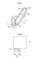
- the reflection optical sensor 150 is used to detect in an area on the intermediate transfer belt 15 where the intermediate transfer belt 15 comes into contact with an area on the photosensitive member 1K where the developing roller 41K has been thus removed from the photosensitive member 1K.
- the area on the intermediate transfer belt 15 is the area where the intermediate transfer belt 15 comes into contact with the area on the photosensitive member 1K where the developing roller 41K does not come into contact with the photosensitive member 1K. Therefore, no toner has adhered to the area on the intermediate transfer belt 15. Accordingly, by detecting in the area on the intermediate transfer belt 15 by means of the reflection optical sensor 150, it is possible to precisely detect a variation in the gloss level on the intermediate transfer belt 15.
- the process including and after step S7 of the toner supply control operation of FIG. 8 may not be carried out and the toner supply control operation may be terminated. Thereby, it is possible to shorten the time period required for the toner supply control operation of FIG. 8 , and it is possible to shorten downtime of the developing apparatus.
- the process including and after step S7 of the toner supply control operation of FIG. 8 is carried out, and a certain amount of new toner is supplied to the developing apparatus.
- the electrifying apparatus 2K uniformly electrifies the surface of the photosensitive member 1K, and the exposure apparatus 130 exposes the entire surface of the photosensitive member 1K.
- the old toner remaining in the developing apparatus 4K adheres to the entire area of an image forming area of the photosensitive member 1K, and thus, it is possible to effectively eject the toner remaining in the developing apparatus 4K to the photosensitive member 1K.
- the old toner thus having been ejected to the surface of the photosensitive member 1K is transferred to the intermediate transfer belt 15, and is removed by the belt cleaning apparatus 33 from the intermediate transfer belt 15.
- such a control method may be used instead that the voltage applied to the electrifying apparatus 2K is turned off, the surface of the photosensitive member 1K is not electrified, and the old toner remaining in the developing apparatus 4K is ejected.
- the electrification electric potential on the surface of the photosensitive member 1K is zero and the predetermined developing bias of negative polarity is applied to the developing roller 41K. Therefore, between the photosensitive member 1K and the developing roller 41K, toner of negative polarity on the developing roller 41K electrostatically moves to the photosensitive member 1K.
- the old toner remaining in the developing apparatus 4K adheres to the entire surface of the image forming area of the photosensitive member 1K.
- the control part 90 as the toner supply amount determining part determines the relational expression corresponding to the operational status of the developing apparatus, and obtains the old toner amount remaining in the developing apparatus after the pre-toner-supply operation, based on the determined relational expression, the detection result from the blank paper image and the new toner amount supplied to the developing apparatus in the pre-toner-supply operation.
Landscapes
- Physics & Mathematics (AREA)
- General Physics & Mathematics (AREA)
- Engineering & Computer Science (AREA)
- Microelectronics & Electronic Packaging (AREA)
- Dry Development In Electrophotography (AREA)
- Control Or Security For Electrophotography (AREA)
Applications Claiming Priority (1)
| Application Number | Priority Date | Filing Date | Title |
|---|---|---|---|
| JP2010049004A JP2011186038A (ja) | 2010-03-05 | 2010-03-05 | 画像形成装置およびトナー供給方法 |
Publications (1)
| Publication Number | Publication Date |
|---|---|
| EP2367063A2 true EP2367063A2 (fr) | 2011-09-21 |
Family
ID=44123451
Family Applications (1)
| Application Number | Title | Priority Date | Filing Date |
|---|---|---|---|
| EP11154264A Withdrawn EP2367063A2 (fr) | 2010-03-05 | 2011-02-14 | Appareil de formation d'images et procédé de fourniture de toner |
Country Status (4)
| Country | Link |
|---|---|
| US (1) | US8483583B2 (fr) |
| EP (1) | EP2367063A2 (fr) |
| JP (1) | JP2011186038A (fr) |
| CN (1) | CN102200729B (fr) |
Families Citing this family (17)
| Publication number | Priority date | Publication date | Assignee | Title |
|---|---|---|---|---|
| JP5408552B2 (ja) | 2010-02-09 | 2014-02-05 | 株式会社リコー | 画像形成装置およびトナー供給方法 |
| JP5660312B2 (ja) | 2011-01-26 | 2015-01-28 | 株式会社リコー | 現像剤搬送装置、現像剤収容器、現像装置、プロセスユニット及び画像形成装置 |
| JP5776186B2 (ja) | 2011-01-27 | 2015-09-09 | 株式会社リコー | 定着装置及び画像形成装置 |
| JP2012226154A (ja) * | 2011-04-20 | 2012-11-15 | Canon Inc | 画像形成装置 |
| JP2013007738A (ja) * | 2011-05-23 | 2013-01-10 | Ricoh Co Ltd | 画像位置検出装置と画像形成装置 |
| JP5835646B2 (ja) | 2011-06-30 | 2015-12-24 | 株式会社リコー | ガイド装置、定着装置及び画像形成装置 |
| JP5822062B2 (ja) | 2011-06-30 | 2015-11-24 | 株式会社リコー | ガイド機構、定着装置及び画像形成装置 |
| JP5805014B2 (ja) * | 2012-06-21 | 2015-11-04 | 京セラドキュメントソリューションズ株式会社 | 画像形成装置 |
| JP6079171B2 (ja) | 2012-11-29 | 2017-02-15 | 株式会社リコー | 画像形成装置、画像形成方法及びプロセスカートリッジ |
| JP6108165B2 (ja) | 2013-06-26 | 2017-04-05 | 株式会社リコー | 現像装置、プロセスユニット、及び画像形成装置 |
| JP6300064B2 (ja) | 2013-11-14 | 2018-03-28 | 株式会社リコー | トナー量検知機構、現像装置、プロセスユニット、及び画像形成装置 |
| JP2016153867A (ja) | 2015-02-22 | 2016-08-25 | 株式会社リコー | 現像装置、画像形成装置、現像剤量検出方法及び現像剤量検出プログラム |
| JP6511877B2 (ja) | 2015-03-10 | 2019-05-15 | 富士ゼロックス株式会社 | 画像形成装置 |
| JP2017167472A (ja) * | 2016-03-18 | 2017-09-21 | 富士ゼロックス株式会社 | 画像形成装置 |
| JP7266483B2 (ja) * | 2019-07-19 | 2023-04-28 | キヤノン株式会社 | 画像形成装置 |
| JP7635534B2 (ja) * | 2020-10-30 | 2025-02-26 | 富士フイルムビジネスイノベーション株式会社 | 画像形成装置 |
| JP2024027896A (ja) * | 2022-08-19 | 2024-03-01 | コニカミノルタ株式会社 | 画像形成装置および判定方法 |
Citations (3)
| Publication number | Priority date | Publication date | Assignee | Title |
|---|---|---|---|---|
| JPH0426977B2 (fr) | 1985-03-06 | 1992-05-08 | Toyoda Machine Works Ltd | |
| JP2009075244A (ja) | 2007-09-19 | 2009-04-09 | Kyocera Mita Corp | 現像装置 |
| JP2010049004A (ja) | 2008-08-21 | 2010-03-04 | Softbank Mobile Corp | 撮影補助器具 |
Family Cites Families (4)
| Publication number | Priority date | Publication date | Assignee | Title |
|---|---|---|---|---|
| JP4026977B2 (ja) | 1999-03-03 | 2007-12-26 | 株式会社リコー | 一成分現像装置 |
| JP2006243115A (ja) * | 2005-03-01 | 2006-09-14 | Konica Minolta Business Technologies Inc | 画像形成装置 |
| JP2008076819A (ja) | 2006-09-22 | 2008-04-03 | Ricoh Co Ltd | トナー消費量算出装置、画像形成装置及びトナー消費量算出方法 |
| JP5403395B2 (ja) | 2008-10-21 | 2014-01-29 | 株式会社リコー | 画像形成装置 |
-
2010
- 2010-03-05 JP JP2010049004A patent/JP2011186038A/ja not_active Withdrawn
-
2011
- 2011-02-11 US US13/025,266 patent/US8483583B2/en not_active Expired - Fee Related
- 2011-02-14 EP EP11154264A patent/EP2367063A2/fr not_active Withdrawn
- 2011-03-02 CN CN201110105480.4A patent/CN102200729B/zh not_active Expired - Fee Related
Patent Citations (3)
| Publication number | Priority date | Publication date | Assignee | Title |
|---|---|---|---|---|
| JPH0426977B2 (fr) | 1985-03-06 | 1992-05-08 | Toyoda Machine Works Ltd | |
| JP2009075244A (ja) | 2007-09-19 | 2009-04-09 | Kyocera Mita Corp | 現像装置 |
| JP2010049004A (ja) | 2008-08-21 | 2010-03-04 | Softbank Mobile Corp | 撮影補助器具 |
Also Published As
| Publication number | Publication date |
|---|---|
| US8483583B2 (en) | 2013-07-09 |
| CN102200729A (zh) | 2011-09-28 |
| CN102200729B (zh) | 2014-04-16 |
| JP2011186038A (ja) | 2011-09-22 |
| US20110217055A1 (en) | 2011-09-08 |
Similar Documents
| Publication | Publication Date | Title |
|---|---|---|
| US8483583B2 (en) | Image forming apparatus and toner supply method | |
| US8594519B2 (en) | Image forming apparatus and toner supply method | |
| US7346286B2 (en) | Method and apparatus for image forming effectively detecting deterioration of developer | |
| EP2569672B1 (fr) | Dispositif de développement d'image, cartouche de traitement comprenant un dispositif de développement d'image et dispositif de formation d'image comprenant le dispositif de développement d'image | |
| US8712261B2 (en) | Lubricant supplying device, process cartridge, and image forming apparatus | |
| US8099002B2 (en) | Developing device of image forming apparatus using a toner and carrier mixture | |
| US8145100B2 (en) | Process cartridge including developing unit and incorporated in image forming apparatus | |
| US7254348B2 (en) | Image forming apparatus with replenishment developer device | |
| JP5245336B2 (ja) | 現像装置、画像形成装置及び画像形成方法 | |
| US11143980B2 (en) | Image forming apparatus | |
| JP2009098160A (ja) | 画像形成装置 | |
| US20090232556A1 (en) | Counting method of mixing time of developer | |
| US10248069B2 (en) | Developing apparatus having a rib portioned conveyance screw | |
| US11599043B2 (en) | Developing apparatus having multi-blade portion replenishment conveyance screw | |
| US11150574B2 (en) | Image forming apparatus | |
| US11249415B2 (en) | Image forming apparatus using two-component developer including toner and carrier that determines toner charge amount based on a developing current | |
| JP4948100B2 (ja) | トナー消費予測量算出方法、トナー消費予測量算出装置、および画像形成装置 | |
| JP5103843B2 (ja) | 画像形成装置 | |
| US9958806B2 (en) | Developing device and image forming apparatus incorporating same | |
| JP2024098924A (ja) | 画像形成装置 | |
| JP2015007673A (ja) | トナー劣化予測方法、トナー劣化予測装置および画像形成装置 | |
| JP2005258224A (ja) | 画像形成装置 |
Legal Events
| Date | Code | Title | Description |
|---|---|---|---|
| PUAI | Public reference made under article 153(3) epc to a published international application that has entered the european phase |
Free format text: ORIGINAL CODE: 0009012 |
|
| 17P | Request for examination filed |
Effective date: 20110214 |
|
| AK | Designated contracting states |
Kind code of ref document: A2 Designated state(s): AL AT BE BG CH CY CZ DE DK EE ES FI FR GB GR HR HU IE IS IT LI LT LU LV MC MK MT NL NO PL PT RO RS SE SI SK SM TR |
|
| AX | Request for extension of the european patent |
Extension state: BA ME |
|
| STAA | Information on the status of an ep patent application or granted ep patent |
Free format text: STATUS: THE APPLICATION HAS BEEN WITHDRAWN |
|
| 18W | Application withdrawn |
Effective date: 20151126 |