EP2367219A2 - Zylinderförmige Sekundärbatterie und Herstellungsverfahren dafür - Google Patents
Zylinderförmige Sekundärbatterie und Herstellungsverfahren dafür Download PDFInfo
- Publication number
- EP2367219A2 EP2367219A2 EP11158421A EP11158421A EP2367219A2 EP 2367219 A2 EP2367219 A2 EP 2367219A2 EP 11158421 A EP11158421 A EP 11158421A EP 11158421 A EP11158421 A EP 11158421A EP 2367219 A2 EP2367219 A2 EP 2367219A2
- Authority
- EP
- European Patent Office
- Prior art keywords
- current
- top part
- sealing assembly
- collecting lead
- upper collector
- Prior art date
- Legal status (The legal status is an assumption and is not a legal conclusion. Google has not performed a legal analysis and makes no representation as to the accuracy of the status listed.)
- Withdrawn
Links
Images


Classifications
-
- H—ELECTRICITY
- H01—ELECTRIC ELEMENTS
- H01M—PROCESSES OR MEANS, e.g. BATTERIES, FOR THE DIRECT CONVERSION OF CHEMICAL ENERGY INTO ELECTRICAL ENERGY
- H01M10/00—Secondary cells; Manufacture thereof
- H01M10/04—Construction or manufacture in general
- H01M10/0422—Cells or battery with cylindrical casing
-
- H—ELECTRICITY
- H01—ELECTRIC ELEMENTS
- H01M—PROCESSES OR MEANS, e.g. BATTERIES, FOR THE DIRECT CONVERSION OF CHEMICAL ENERGY INTO ELECTRICAL ENERGY
- H01M50/00—Constructional details or processes of manufacture of the non-active parts of electrochemical cells other than fuel cells, e.g. hybrid cells
- H01M50/50—Current conducting connections for cells or batteries
- H01M50/543—Terminals
-
- H—ELECTRICITY
- H01—ELECTRIC ELEMENTS
- H01M—PROCESSES OR MEANS, e.g. BATTERIES, FOR THE DIRECT CONVERSION OF CHEMICAL ENERGY INTO ELECTRICAL ENERGY
- H01M10/00—Secondary cells; Manufacture thereof
- H01M10/24—Alkaline accumulators
- H01M10/28—Construction or manufacture
- H01M10/286—Cells or batteries with wound or folded electrodes
-
- H—ELECTRICITY
- H01—ELECTRIC ELEMENTS
- H01M—PROCESSES OR MEANS, e.g. BATTERIES, FOR THE DIRECT CONVERSION OF CHEMICAL ENERGY INTO ELECTRICAL ENERGY
- H01M50/00—Constructional details or processes of manufacture of the non-active parts of electrochemical cells other than fuel cells, e.g. hybrid cells
- H01M50/10—Primary casings; Jackets or wrappings
- H01M50/147—Lids or covers
- H01M50/166—Lids or covers characterised by the methods of assembling casings with lids
- H01M50/167—Lids or covers characterised by the methods of assembling casings with lids by crimping
-
- H—ELECTRICITY
- H01—ELECTRIC ELEMENTS
- H01M—PROCESSES OR MEANS, e.g. BATTERIES, FOR THE DIRECT CONVERSION OF CHEMICAL ENERGY INTO ELECTRICAL ENERGY
- H01M50/00—Constructional details or processes of manufacture of the non-active parts of electrochemical cells other than fuel cells, e.g. hybrid cells
- H01M50/10—Primary casings; Jackets or wrappings
- H01M50/147—Lids or covers
- H01M50/166—Lids or covers characterised by the methods of assembling casings with lids
- H01M50/171—Lids or covers characterised by the methods of assembling casings with lids using adhesives or sealing agents
-
- H—ELECTRICITY
- H01—ELECTRIC ELEMENTS
- H01M—PROCESSES OR MEANS, e.g. BATTERIES, FOR THE DIRECT CONVERSION OF CHEMICAL ENERGY INTO ELECTRICAL ENERGY
- H01M50/00—Constructional details or processes of manufacture of the non-active parts of electrochemical cells other than fuel cells, e.g. hybrid cells
- H01M50/10—Primary casings; Jackets or wrappings
- H01M50/183—Sealing members
-
- H—ELECTRICITY
- H01—ELECTRIC ELEMENTS
- H01M—PROCESSES OR MEANS, e.g. BATTERIES, FOR THE DIRECT CONVERSION OF CHEMICAL ENERGY INTO ELECTRICAL ENERGY
- H01M50/00—Constructional details or processes of manufacture of the non-active parts of electrochemical cells other than fuel cells, e.g. hybrid cells
- H01M50/30—Arrangements for facilitating escape of gases
- H01M50/317—Re-sealable arrangements
- H01M50/325—Re-sealable arrangements comprising deformable valve members, e.g. elastic or flexible valve members
- H01M50/333—Spring-loaded vent valves
-
- H—ELECTRICITY
- H01—ELECTRIC ELEMENTS
- H01M—PROCESSES OR MEANS, e.g. BATTERIES, FOR THE DIRECT CONVERSION OF CHEMICAL ENERGY INTO ELECTRICAL ENERGY
- H01M50/00—Constructional details or processes of manufacture of the non-active parts of electrochemical cells other than fuel cells, e.g. hybrid cells
- H01M50/50—Current conducting connections for cells or batteries
- H01M50/528—Fixed electrical connections, i.e. not intended for disconnection
-
- H—ELECTRICITY
- H01—ELECTRIC ELEMENTS
- H01M—PROCESSES OR MEANS, e.g. BATTERIES, FOR THE DIRECT CONVERSION OF CHEMICAL ENERGY INTO ELECTRICAL ENERGY
- H01M50/00—Constructional details or processes of manufacture of the non-active parts of electrochemical cells other than fuel cells, e.g. hybrid cells
- H01M50/50—Current conducting connections for cells or batteries
- H01M50/531—Electrode connections inside a battery casing
- H01M50/533—Electrode connections inside a battery casing characterised by the shape of the leads or tabs
-
- H—ELECTRICITY
- H01—ELECTRIC ELEMENTS
- H01M—PROCESSES OR MEANS, e.g. BATTERIES, FOR THE DIRECT CONVERSION OF CHEMICAL ENERGY INTO ELECTRICAL ENERGY
- H01M50/00—Constructional details or processes of manufacture of the non-active parts of electrochemical cells other than fuel cells, e.g. hybrid cells
- H01M50/50—Current conducting connections for cells or batteries
- H01M50/531—Electrode connections inside a battery casing
- H01M50/534—Electrode connections inside a battery casing characterised by the material of the leads or tabs
-
- H—ELECTRICITY
- H01—ELECTRIC ELEMENTS
- H01M—PROCESSES OR MEANS, e.g. BATTERIES, FOR THE DIRECT CONVERSION OF CHEMICAL ENERGY INTO ELECTRICAL ENERGY
- H01M50/00—Constructional details or processes of manufacture of the non-active parts of electrochemical cells other than fuel cells, e.g. hybrid cells
- H01M50/50—Current conducting connections for cells or batteries
- H01M50/531—Electrode connections inside a battery casing
- H01M50/536—Electrode connections inside a battery casing characterised by the method of fixing the leads to the electrodes, e.g. by welding
-
- Y—GENERAL TAGGING OF NEW TECHNOLOGICAL DEVELOPMENTS; GENERAL TAGGING OF CROSS-SECTIONAL TECHNOLOGIES SPANNING OVER SEVERAL SECTIONS OF THE IPC; TECHNICAL SUBJECTS COVERED BY FORMER USPC CROSS-REFERENCE ART COLLECTIONS [XRACs] AND DIGESTS
- Y02—TECHNOLOGIES OR APPLICATIONS FOR MITIGATION OR ADAPTATION AGAINST CLIMATE CHANGE
- Y02E—REDUCTION OF GREENHOUSE GAS [GHG] EMISSIONS, RELATED TO ENERGY GENERATION, TRANSMISSION OR DISTRIBUTION
- Y02E60/00—Enabling technologies; Technologies with a potential or indirect contribution to GHG emissions mitigation
- Y02E60/10—Energy storage using batteries
-
- Y—GENERAL TAGGING OF NEW TECHNOLOGICAL DEVELOPMENTS; GENERAL TAGGING OF CROSS-SECTIONAL TECHNOLOGIES SPANNING OVER SEVERAL SECTIONS OF THE IPC; TECHNICAL SUBJECTS COVERED BY FORMER USPC CROSS-REFERENCE ART COLLECTIONS [XRACs] AND DIGESTS
- Y02—TECHNOLOGIES OR APPLICATIONS FOR MITIGATION OR ADAPTATION AGAINST CLIMATE CHANGE
- Y02P—CLIMATE CHANGE MITIGATION TECHNOLOGIES IN THE PRODUCTION OR PROCESSING OF GOODS
- Y02P70/00—Climate change mitigation technologies in the production process for final industrial or consumer products
- Y02P70/50—Manufacturing or production processes characterised by the final manufactured product
-
- Y—GENERAL TAGGING OF NEW TECHNOLOGICAL DEVELOPMENTS; GENERAL TAGGING OF CROSS-SECTIONAL TECHNOLOGIES SPANNING OVER SEVERAL SECTIONS OF THE IPC; TECHNICAL SUBJECTS COVERED BY FORMER USPC CROSS-REFERENCE ART COLLECTIONS [XRACs] AND DIGESTS
- Y10—TECHNICAL SUBJECTS COVERED BY FORMER USPC
- Y10T—TECHNICAL SUBJECTS COVERED BY FORMER US CLASSIFICATION
- Y10T29/00—Metal working
- Y10T29/49—Method of mechanical manufacture
- Y10T29/49002—Electrical device making
- Y10T29/49108—Electric battery cell making
- Y10T29/4911—Electric battery cell making including sealing
Definitions
- the present invention relates to a secondary battery such as a nickel-metal hydride storage battery or a nickel-cadmium storage battery. More particularly, the invention relates to a cylindrical secondary battery, in which an upper collector is welded to one electrode substrate extending from an upper portion of a spiral electrode group having a positive electrode plate and a negative electrode plate spirally wound with a separator interposed therebetween, and the upper collector is connected through a current-collecting lead to a sealing assembly for sealing a mouth portion of a cylindrical metal outer can. The invention also relates to a method of manufacturing the cylindrical secondary battery.
- a cylindrical secondary battery such as a nickel-metal hydride storage battery or a nickel-cadmium storage battery has a sealed structure formed as follows. A positive electrode plate and a negative electrode plate are spirally wound with a separator interposed therebetween. Collectors are connected to the end portions of the positive electrode plate and the negative electrode plate to form an electrode assembly. The electrode assembly is accommodated in a metal outer can, and a lead portion extending from the positive electrode collector is welded to a sealing assembly. The sealing assembly is then attached to a mouth portion of the outer can with an insulating gasket interposed therebetween.
- HEV Hybrid Electric Vehicles
- PEV Purific Electric Vehicles
- JP-A-2006-331993 proposes a technique for reducing the internal resistance of a battery.
- a current-collecting lead with a truncated cone shape is connected by welding between a positive electrode collector and a sealing assembly.
- the use of such a current-collecting lead with a truncated cone shape shortens the current-collecting path between the positive electrode collector and the sealing assembly, thereby reducing the internal resistance.
- the current-collecting lead 60 proposed in JP-A-2006-331993 includes a plate-shaped top part 61, a lateral wall part 62 extending obliquely downwardly from the outer periphery of the top part 61 so as to expand, and a flange portion 63 arranged at the outer periphery of the lower end of the lateral wall part 62.
- Slits 64 are longitudinally formed in the lateral wall part 62 and the flange portion 63 from the lower ends at circumferential intervals.
- the lateral wall part 62 between the slits 64 formed in the lateral wall part 62 and the flange portion 63 is bent outwardly to expand so as to absorb the height and maintain appropriate contact pressure (pressure at contact points).
- welding projections 63a are provided at parts of the flange portion 63 that are sandwiched between slits 64 in order to form welding spots between the current-collecting lead 60 and the not-shown positive electrode collector (upper collector).
- welding projections 61b are provided around a central opening 61a of the top part 61 in order to form welding spots between the top part 61 and the sealing assembly. Projection welding is carried out using the welding projections 61b and the welding projections 63a.
- the top part 61 of the current-collecting lead 60 and the sealing assembly are connected together only at the welding spots formed by the welding projections 61b provided on the top part 61.
- the welding projections 61b are formed on the limited plane of the top part 61, the number of the arranged welding projections 61b is limited.
- the internal resistance of the battery is increased to cause an output loss. Therefore, a high-power cylindrical secondary battery cannot be obtained.
- the resistance of the current-collecting lead can be reduced by increasing the thickness of the current-collecting lead.
- the thickness of the current-collecting lead is increased, the mechanical strength of the current-collecting lead becomes excessively high. This makes it difficult for the current-collecting lead to collapse at the time of welding the sealing assembly to the current-collecting lead and at the time of sealing. This result in variations in battery height, which poses a new problem that the essential function of the current-collecting leads cannot be maintained.
- An advantage of some aspects of the present invention is to provide a cylindrical secondary battery with excellent output characteristics by using a current-collecting lead having excellent current-collecting performance to reduce internal resistance.
- an upper collector is welded to one electrode substrate extending from an upper portion of a spiral electrode group having a positive electrode plate and a negative electrode plate spirally wound with a separator interposed therebetween.
- the upper collector is connected through a current-collecting lead to a sealing assembly for sealing a mouth portion of a cylindrical metal outer can.
- the current-collecting lead formed by press-forming a metal plate includes: a flat surface part formed in approximately the same shape as an outer shape of the upper collector and welded to the upper collector, and a top part formed to be curved and protrude approximately in the shape of a dome from the flat surface part and welded to the sealing assembly.
- a central opening is formed at a central portion of the top part.
- a plurality of welding projections are formed to protrude from the top part toward the sealing assembly.
- the plurality of welding projections serve as welding spots to the sealing assembly.
- the top part is deformed by a pressing force from the sealing assembly to be brought into surface contact with a corner portion of a convex portion formed on a lower surface of the sealing assembly.
- this aspect of the invention provides a cylindrical secondary battery having excellent output characteristics with reduced internal resistance.
- a plurality of welding projections may be formed at the convex portion formed on the lower surface of the sealing assembly so as to protrude from the convex portion toward the periphery of the central opening of the top part, and the plurality of welding projections may serve as the welding spots to the top part.
- an upper flat surface portion is formed in a region including the central portion of the top part.
- an inner angle R1 between the upper flat surface portion and the inclined region of the top part is set to be 152° or more and 165° or less (152° ⁇ R1 ⁇ 165°)
- the current-collecting lead is easily deformed by the pressing force at the time of sealing the battery, thereby preventing the deformation of the bottom of the battery can and the deformation of the sealing assembly by the pressing force. Therefore, it is preferable that the inner angle R1 between the upper flat surface portion and the inclined region of the top part be 152° or more and 165° or less (152° ⁇ R1 ⁇ 165°).
- an outer angle R2 between the flat surface part and the inclined region of the top part is 90° or more and 115° or less (90° ⁇ R2 ⁇ 115°)
- the current-collecting lead is easily deformed by the pressing force at the time of sealing the battery, thereby preventing the deformation of the bottom of the battery can and the deformation of the sealing assembly by the pressing force. Therefore, it is preferable that the outer angle R2 between the flat surface part and the inclined region of the top part be 90° or more and 115° or less (90° ⁇ R2 ⁇ 115°).
- D2 > D1 is satisfied where D1 is the diameter of the convex portion formed on the lower surface of the sealing assembly and D2 is the diameter of a base portion of the top part that is adjacent to the flat surface part.
- the dome-shaped top part is easily deformed by the pressing force at the time of sealing the battery. This makes it possible to increase the thickness of the current-collecting lead of this kind. Accordingly, a current-collecting lead with even lower resistance can be achieved.
- a central opening be formed at the central portion of the upper collector.
- a plurality of inner slits open to the central opening and arranged radially from the central opening toward the peripheral portion and a plurality of outer slits open to the outside of the upper collector and arranged radially toward the central opening are formed by a burring process.
- the burrs formed at the end portions of the inner and outer slits are welded to one electrode substrate extending from the upper portion of the spiral electrode group. Accordingly, the welding spots to one electrode substrate can be formed uniformly from the central portion to the outer peripheral portion of the spiral electrode group.
- the ratio between the number of outer slits and the number of inner slits be 2:1. This compensates for reduced current-collecting performance resulting from the increased distance between the welding spots to the substrate exposed at one electrode end portion, at the outer peripheral portion of the spiral electrode group. Therefore, this aspect of the invention provides a cylindrical secondary battery with improved current-collecting performance and with reduced internal resistance. It is preferable that a semicircular burring hole be formed at the outer peripheral portion of the upper collector, and the semicircular burring hole be welded to one electrode substrate extending from the upper portion of the spiral electrode group. Accordingly, a number and an area of welding spots are increased at the outer peripheral portion of the spiral electrode group, thereby further improving the current-collecting performance.
- a beveled portion be formed at a tip end of a sidewall of the outer slit formed in the upper collector. This prevents snagging of the upper collector during production thereby improving ease of handling and thus production efficiency. It is preferable that, in the outer peripheral portion of the flat surface part welded to the upper collector, semicircular openings each having the same shape as the semicircular burring hole be formed at locations corresponding to a plurality of semicircular burring holes formed in the outer peripheral portion of the upper collector. Accordingly, the positioning of the current-collecting lead with the collector is facilitated with extremely high precision.
- This aspect of the invention provides a cylindrical secondary battery of high quality with high reliability.
- a method of manufacturing such a cylindrical secondary battery includes: welding an upper collector to one electrode substrate extending from an upper portion of the spiral electrode group; welding a current-collecting lead to the upper collector, the current-collecting lead being formed by press-forming a metal plate and including a flat surface part formed in approximately the same shape as the outer shape of the upper collector and a top part formed to be curved and protrude approximately in the shape of a dome from the flat surface part, the top part having a central opening at a central portion thereof and a plurality of welding projections formed around the central opening to protrude from the top part toward a sealing assembly; accommodating the electrode group with the current-collecting lead welded to the upper collector in a cylindrical metal outer can, and thereafter pouring an electrolyte into the outer can; arranging the sealing assembly, having a convex portion on the lower surface thereof, on a mouth portion of the outer can containing the electrolyte, bringing the sealing assembly into abutment with the top part of the current-collect
- a plurality of welding projections may be formed on the convex portion on the lower surface of the sealing assembly so as to protrude from the convex portion toward the periphery of the central opening of the top part, and contact portions between the plurality of welding projections and the top part may be welded.
- the current-collecting efficiency from the current-collecting lead to the sealing assembly is enhanced, and therefore, a cylindrical secondary battery with reduced internal resistance and having excellent output characteristics is provided.
- a cylindrical secondary battery according to the invention will be described based on Fig. 1 to Fig. 4 .
- a nickel-metal hydride storage battery is used as a cylindrical secondary battery, by way of example.
- the invention is not limited thereto and can be modified as appropriate without departing from the scope and spirits of the technical concepts set forth in the claims.
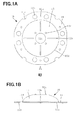
- a current-collecting lead 10 in this embodiment (in this case, a current-collecting lead for the positive electrode) is formed in the shape of a predetermined dome by press-forming a nickel-plated steel plate (in this case, having a thickness of 0.3 mm).
- the current-collecting lead 10 includes an approximately ring-shaped flat surface part 11 to be welded to an upper collector (in this case, positive electrode collector) 20, which will be described later, and a top part 12 formed to be curved and protrude approximately in the shape of a dome from the flat surface part 11.
- the top part 12 is to be welded to a sealing assembly 36, which will be described later (see Figs. 3 and 4 ).
- Openings (circular openings) 11a are formed on the circumference on the approximately central line of the approximately ring-shaped flat surface part 11 and at locations corresponding to circular burring holes 22 formed in the upper collector 20 as described later.
- the openings 11a have the same shape as that of the burring holes 22.
- First welding projections 11b to be welded to the upper collector 20 are formed at approximately regular intervals on the circumference on the approximately central line of the approximately ring-shaped flat surface part 11 and at locations where openings 11a are not arranged.
- the first welding projections 11b are formed to protrude toward the upper collector 20 (from the front face toward the back face of the drawing sheet in Fig. 1A and Fig. 2B ).
- openings (semicircular openings) 11c are formed at locations corresponding to semicircular burring holes 24 formed in the outer peripheral portion of the upper collector 20.
- the openings 11c have the same shape as that of the burring holes 24.
- the openings 11a having the same shape as that of the burring holes 22 are formed at locations corresponding to the burring holes 22 formed in the upper collector 20, the openings 11a and the burring holes 22 are connected in communication with each other to function as an inlet for electrolyte. Accordingly, when electrolyte is poured into the outer can after the current-collecting lead 10 is welded to the upper collector 20, the electrolyte can easily penetrate into the electrode group through the openings 11a and the burring holes 22.
- the first welding projections 11b are formed to protrude at approximately regular intervals on the circumference on the approximately central line of the flat surface part 11, electric current can be collected uniformly from the upper collector 20 to the current-collecting lead 10.
- the openings 11c having the same shape as that of the burring holes 24 are formed at locations corresponding to the semicircular burring holes 24 formed in the outer peripheral portion of the upper collector 20, the positioning of the current-collecting lead 10 with the upper collector 20 is facilitated with extremely high precision.
- the provision of the semicircular burring holes 24 increases a number and an area of the welding spots on the periphery, thereby improving the current-collecting performance.
- a plurality of slits 12b are formed at regular intervals to extend radially toward the flat surface part 11, from a starting point at a predetermined distance away from a central opening 12a to an end point at a predetermined distance away from a base portion adjacent to the flat surface part 11.
- the central opening 12a is formed at the central portion that is the apex of the top part 12.
- a plurality of second welding projections 12c to be welded to a sealing plate 36a of the sealing assembly 36 are formed at approximately regular intervals around the central opening 12a so as to protrude toward the sealing assembly 36 (from the back face toward the front face of the drawing sheet in Fig.1A and Fig. 2B ).
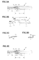
- a convex portion 36a-1 protruding downward is formed at the central portion of the sealing plate 36a.
- a base portion 12d is formed so as to satisfy the relation D2 > D1, where D1 is the diameter of the convex portion 36a-1 and D2 is the diameter of the base portion 12d of the top part 12 adjacent to the flat surface part 11. Accordingly, the pressing force from the sealing assembly 36 at the time of sealing the battery causes the convex portion 36a-1 formed on the lower surface of the sealing assembly 36 to thrust into and deform the dome-shaped top part 12.
- the top part 12 can be brought into surface contact with the corner portion of the convex portion 36a-1 formed on the lower surface of the sealing assembly 36.
- the dome-shaped top part 12 can be easily deformed by the pressing force from the sealing assembly 36 at the time of sealing the battery. This makes it possible to increase the thickness of the current-collecting lead 10, resulting in the current-collecting lead 10 with low resistance. Furthermore, since the second welding projections 12c protruding toward the sealing assembly 36 are formed around the central opening 12a of the top part 12 to serve as welding spots to the sealing assembly 36, electric current can be collected uniformly from the current-collecting lead 10 to the sealing assembly 36.
- an upper flat surface portion 12e is formed in a region including the central portion of the top part 12.
- an inner angle R1 (see Fig. 3C ) between the upper flat surface portion 12e and the inclined region of the top part 12 is set to be 152° or more and 165° or less (152° ⁇ R1 165°). This is because it has been revealed that if the inner angle R1 between the upper flat surface portion 12e and the inclined region of the top part 12 is set to be 152° or more and 165° or less (152° ⁇ R1 ⁇ 165°), the current-collecting lead 10 is easily deformed by the pressing force at the time of sealing the battery. If the current-collecting lead 10 is easily deformed, the deformation of the bottom of an outer can 35 (see Fig. 4 ) and the deformation of the sealing assembly 36 (see Fig. 4 ) by the pressing force can be prevented.
- an outer angle R2 between the flat surface part 11 and the inclined region of the top part 12 is set to be 90° or more and 115° or less (90° ⁇ R2 ⁇ 115°). This is because it has been revealed that if the outer angle R2 (see Fig. 3D ) between the flat surface part 11 and the inclined region of the top part 12 is set to be 90° or more and 115° or less (90° ⁇ R2 ⁇ 115°), the current-collecting lead 10 can be easily deformed by the pressing force at the time of sealing the battery.
- the current-collecting lead 10 can be deformed even more easily, thereby preventing the deformation of the bottom of the outer can 35 (see Fig. 4 ) and the deformation of the sealing assembly 36 (see Fig. 4 ) by the pressing force.
- a current-collecting lead 60 of a comparative example is formed by press-forming a nickel-plated steel plate (in this case, having a thickness of 0.3 mm).
- the current-collecting lead 60 includes a plate-like top part 61 and a lateral wall part 62 extending obliquely downwardly from the outer periphery of the top part 61.
- a flange portion 63 is formed at the outer periphery of the lower end of the lateral wall part 62.
- Slits 64 are longitudinally formed in the lateral wall part 62 and the flange portion 63 from the lower ends at circumferential intervals.
- a central opening 61a is provided at the central portion of the top part 61.
- a plurality of second welding projections 61b protruding toward a sealing assembly are formed to serve as welding spots when being welded to the bottom surface of the sealing assembly.
- First welding projections 63a are provided toward a positive electrode collector (upper collector) (from the front face to the back face of the drawing sheet in Fig. 13 ) between slits 64 in the flange portion 63 in order to form welding spots to the positive electrode collector (upper collector). Then, projection welding is carried out using the second welding projections 61b and the first welding projections 63a.
- a nickel sintered porous body is formed on a surface of an electrode plate substrate of perforated metal. Then, the pores of the nickel sintered porous body are impregnated with a nickel hydroxide-based active material by chemical impregnation. Then, after being dried, the resultant product is rolled to a predetermined thickness and is cut to a predetermined size to form a nickel positive electrode plate 31. At one end (the upper portion in Fig. 4 ) in the width direction of the nickel positive electrode plate 31, a substrate-exposed portion 31a is formed in which the electrode plate substrate is exposed.
- a paste-like negative electrode active material mainly including hydrogen storage alloy is coated on the surface of an electrode plate substrate of perforated metal. After being dried, the resultant product is rolled to a predetermined thickness and is cut to a predetermined size to form a hydrogen storage alloy negative electrode plate 32. At one end (not shown) in the width direction of the hydrogen storage alloy negative electrode plate 32, a substrate-exposed portion (not shown) is formed in which the electrode plate substrate is exposed. Then, as shown in Fig. 4 , the nickel positive electrode plate 31 and the hydrogen storage alloy negative electrode plate 32 are spirally wound with a separator 33 interposed to form a spiral electrode group 30a. It is noted that the substrate-exposed portion 31a protrudes at one end (the upper portion in Fig. 4 ) in the height direction of the spiral electrode group 30a and the substrate-exposed portion (not shown) protrudes at the other end (not shown).
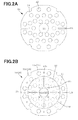
- the positive electrode collector (in this case, the upper collector) 20 is formed in an approximately circular shape (having the maximum diameter of 30 mm).
- a central opening 21 for receiving a welding electrode is formed at the central portion of the positive electrode collector 20.
- a number of burring holes 22 are formed from the periphery of the central opening 21 toward the end portion.
- a pair of slits 23 open to the edge and two pairs of the semicircular burring holes 24 are formed in order to decrease reactive welding current and to increase active welding current.
- the negative electrode collector in this case, the lower collector
- the negative electrode collector has a structure generally similar to that of the positive electrode collector 20 as described above, and therefore, a detailed description thereof is not repeated here.
- Fig. 4 is formed as a cylindrical secondary battery using the spiral electrode group 30a having the above-noted structure, the positive electrode collector 20, the negative electrode collector, and the current-collecting lead 10 (60) as described above.
- the negative electrode collector is welded to the substrate-exposed portion (not shown) of the hydrogen storage alloy negative electrode plate 32 that is exposed at the lower end surface of the spiral electrode group 30a.
- the positive electrode collector 20 is welded to the substrate-exposed portion 31a of the nickel positive electrode plate 31 that is exposed at the upper end surface of the spiral electrode group 30a.
- an electrode assembly is formed.
- the current-collecting lead 10 (60) is arranged on the positive electrode collector 20 welded to the upper end of the spiral electrode group 30a. Then, a welding electrode is pushed onto the upper surface portions of the first welding projections 11b (63a) to spot-weld the current-collecting lead 10 (60) to the positive electrode collector 20. Accordingly, using the first welding projections 11b or 63a formed on the ring-shaped flat surface part 11 or the flange portion 63 of the current-collecting lead 10 (60) as welding spots, the current-collecting lead 10 (60) is welded to the positive electrode collector 20.
- the spiral electrode group 30a with the current-collecting lead 10 (60) welded to the positive electrode collector 20 is accommodated in the nickel-plated iron outer can 35 shaped in a cylinder with a base (whose outer bottom surface serves as a negative electrode external terminal). Then, a welding electrode is inserted into a space formed in the central portion of the spiral electrode group 30a to spot-weld the negative electrode collector welded to the hydrogen storage alloy negative electrode plate 32, to the inner bottom surface of the outer can 35. Accordingly, the negative electrode collector is welded to the inner bottom surface of the outer can 35.
- an insulating ring (not shown) is inserted on the upper inner circumference of the outer can 35, and a groove is formed on the upper outer circumference of the outer can 35 to form an annular concave portion 35a at the upper end portion of the insulating ring.
- alkaline electrolyte in the form of an aqueous solution of 7N potassium hydroxide (KOH) is poured into the outer can 35.
- the sealing assembly 36 is arranged on the current-collecting lead 10 (60). As shown in Fig. 3 , the sealing assembly 36 is formed from a sealing plate 36a and a positive electrode cap (positive electrode external terminal) 36b.
- a valve including a valve plate 36c and a spring 36d. Therefore, at the central portion of the sealing plate 36a, a convex portion 36a-1 is formed to protrude downward. In the middle of the sealing assembly 36, a vent hole is formed, and around the periphery of the sealing assembly 36, an insulating gasket 37 is fitted beforehand.
- a pair of welding electrodes is arranged at the top of the sealing assembly 36 and the bottom of the outer can 35. Thereafter, under pressure of 2 ⁇ 10 6 N/m 2 , a voltage of 24 V is applied between the pair of welding electrodes and welding current of 3 kA is fed for 15 msec to perform a welding process.
- the sealing assembly 36 is welded to the current-collecting lead 10 (60).
- a mouth edge 35b of the outer can 35 is crimped inward and sealed, resulting in a 6.0 Ah nickel-metal hydride storage battery A (using the current-collecting lead 10) as shown in Fig. 4 and a 6.0 Ah nickel-metal hydride storage battery B (using the current-collecting lead 60).
- the convex portion 36a-1 formed on the lower surface of the sealing plate 36a of the sealing assembly 36 is thrust into and deforms the dome-shaped top part 12 by the pressing force at the time of sealing. Accordingly, the top part 12 can be brought into surface contact with the corner portion of the convex portion 36a-1 formed on the lower surface of the sealing assembly 36.
- the batteries A and B fabricated as described above were charged to 120% of SOC with charging current of 1 It in an atmosphere at a temperature of 25°C, and after 1-hour interval, discharged with discharging current of 1 It in an atmosphere at a temperature of 25°C until the battery voltages reached 0.9 V.
- This charge/discharge cycle was repeated 10 times to activate the batteries.
- the batteries A and B of 20 cells each were charged with charging current of 1 It in the atmosphere at a temperature of 25°C up to 50% battery capacity and left for 1 hour in an open circuit state. Thereafter, charge/discharge for 10 seconds was repeated up to 200 A, with 30-minute intervals between the steps.
- the 10th-second discharge power ratio of the battery B is 100
- the 10th-second discharge power ratio of the battery A is 103
- the connection between the top part 61 of the current-collecting lead 60 and the sealing assembly 36 is point connection brought about by the second welding projections 61b provided on the top part 61, so that the internal resistance of the battery is increased to cause an output loss, thereby decreasing the output characteristics.
- the pressing force at the time of sealing causes the convex portion 36a-1 formed on the lower surface of the sealing plate 36a of the sealing assembly 36 to thrust into and deform the dome-shaped top part 12, so that the top part 12 can be brought into surface contact with the corner portion of the convex portion 36a-1 formed on the lower surface of the sealing assembly 36.
- the surface contact increases the contact with the sealing assembly 36, thereby enhancing the current-collecting efficiency from the current-collecting lead 10 to the sealing assembly 36.
- the internal resistance is reduced, thereby achieving excellent output characteristics.
- the slits 12b are formed at regular intervals radially toward the flat surface part 11 at a distance away from the central opening 12a formed at the central portion of the top part 12, so that the dome-shaped top part 12 is easily deformed by the pressing force at the time of sealing the battery.
- the openings 11a having the same shape as that of the burring holes 22 are formed at locations corresponding to the burring holes 22 formed in the upper collector 20, so that the poured electrolyte can easily penetrate into the electrode group 30a, thereby improving the productivity of batteries of this kind.
- the semicircular holes 11c having the same shape as that of the burring holes 24 are formed at locations corresponding to the semicircular burring holes 24 formed in the outer peripheral portion of the upper collector 20, so that the positioning of the current-collecting lead 10 with the upper collector 20 is facilitated with extremely high precision.
- the provision of the semicircular burring holes 24 increases a number and an area of welding spots in the outer peripheral portion, thereby improving the current-collecting performance.
- the upper collector (positive electrode collector) 20 including a number of circular burring holes 22 is used.
- the upper collector (positive electrode collector) suitable for the above-noted current-collecting lead is applicable to various modifications. Then, suitable modifications of the upper collector (positive electrode collector) are discussed below.
- An upper collector (in this case, a positive electrode collector) 20a according to a first modification is formed in an approximately circular shape (having the maximum diameter of 30 mm), as shown in Fig. 5A .
- a central opening 21a for receiving a welding electrode is formed at the central portion.
- a plurality of (four in this example, although any appropriate number can be set) inner slits 22a open to the central opening 21a are arranged radially from the central opening 21a toward the peripheral portion.
- a plurality of (eight in this example, although any appropriate number can be set) outer slits 23a open to the outside of the upper collector 20a are arranged radially toward the central opening 21a.
- the inner slits 22a and the outer slits 23a are formed by a burring process. In this case, the ratio between the number of outer slits 23a and the number of inner slits 22a is set to be 2:1.
- an appropriate number (eight in this example) of semicircular burring holes 24a are formed in the outer peripheral portion of the upper collector 20a.
- the provision of the semicircular burring holes 24a in the outer peripheral portion of the upper collector 20a increases a number and an area of welding spots in the outer peripheral portion and improves the current-collecting performance.
- a beveled portion X is formed at the tip end of the sidewall of the outer slit 23a. In this manner, the provision of the beveled portion X at the tip end of the sidewall of the outer slit 23a prevents snagging of the upper collector 20a and thus improves ease of handling, thereby improving production efficiency.
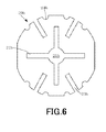
- An upper collector 20b (in this case, a positive electrode collector) according to a second modification is formed in an approximately circular shape (having the maximum diameter of 30 mm), as shown in Fig. 6 .
- a central opening 21b for receiving a welding electrode is formed at the central portion.
- a plurality of (four in this example, although any appropriate number can be set) inner slits 22b open to the central opening 21b are arranged radially from the central opening 21b toward the peripheral portion.
- a plurality of (four in this example, although any appropriate number can be set) outer slits 23b open to the outside of the upper collector 20b are arranged radially toward the central opening 21b.
- the inner slits 22b and the outer slits 23b are formed by a burring process.
- an appropriate number (eight in this example) of semicircular burring holes 24b are formed in the outer peripheral portion of the upper collector 20b.
- a beveled portion X as shown in Fig. 5B is formed at the tip end of the sidewall of the outer slit 23b.
- An upper collector (in this case, a positive electrode collector) 20c according to a third modification is formed in an approximately circular shape (having the maximum diameter of 30 mm), as shown in Fig. 7 .
- a central opening 21c for receiving a welding electrode is formed at the central portion.
- a plurality of (four in this example, although any appropriate number can be set) outer slits 23c open to the outside of the upper collector 20c are arranged radially toward the central opening 21c.
- the outer slits 23c are formed by a burring process.
- an appropriate number (eight in this example) of semicircular burring holes 24c are formed in the outer peripheral portion of the upper collector 20c.
- a beveled portion X as shown in Fig. 5B is formed at the tip end of the sidewall of the outer slit 23c.
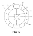
- An upper collector (in this case, a positive electrode collector) 20d according to a fourth modification is formed in an approximately circular shape (having the maximum diameter of 30 mm), as shown in Fig. 8 .
- a central opening 21d for receiving a welding electrode is formed at the central portion.
- a plurality of (eight in this example, although any appropriate number can be set) outer slits 23d open to the outside of the upper collector 20d are arranged radially toward the central opening 21d.
- the outer slits 23d are formed by a burring process.
- an appropriate number (eight in this example) of semicircular burring holes 24d are formed in the outer peripheral portion of the upper collector 20d.
- a beveled portion X as shown in Fig. 5B is formed at the tip end of the sidewall of the outer slit 23d.
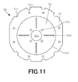
- An upper collector (in this case, a positive electrode collector) 20e according to a fifth modification is formed in an approximately circular shape (having the maximum diameter of 30 mm), as shown in Fig. 9 .
- a central opening 21e for receiving a welding electrode is formed at the central portion.
- a plurality of (three in this example, although any appropriate number can be set) outer slits 23e open to the outside of the upper collector 20e are arranged radially toward the central opening 21e.
- a communication slit 23f open to the outside is formed in communication with the central opening 21e.
- the outer slits 23e and the communication slit 23f are formed by a burring process.
- an appropriate number (eight in this example) of semicircular burring holes 24e are formed in the outer peripheral portion of the upper collector 20e.
- beveled portions X as shown in Fig. 5B are formed at the tip end of the sidewall of the outer slit 23e and the tip end of the sidewall of the communication slit 23f.
- the current-collecting lead (positive electrode current-collecting lead) 10 includes the openings 11a formed on the circumference on the approximately central line of the flat surface part 11 and the six first welding projections 11b formed at approximately regular intervals at locations where the openings 11a are not arranged.
- the current-collecting lead suitable for the upper collectors (positive electrode collectors) according to the modifications above is also applicable to various modifications. Modifications of the current-collecting lead (positive electrode current-collecting lead) are discussed below.
- a current-collecting lead (in this case, a current-collecting lead for the positive electrode) 40 according to a first modification has a configuration almost similar to that of the current-collecting lead 10 in the foregoing embodiment.
- the current-collecting lead 40 includes an approximately ring-shaped flat surface part 41 to be welded to the upper collectors 20, 20a, 20b, 20c, 20d, or 20e and a top part 42 formed to be curved and protrude approximately in the shape of a dome from the flat surface part 41 and to be welded to the sealing assembly 36.
- twelve first welding projections 41b are formed at regular intervals on the circumference on the approximately central line of the approximately ring-shaped flat surface part 41 so as to protrude toward the upper collectors 20, 20a, 20b, 20c, 20d, or 20e.
- Openings 41c having the same shape as that of burring holes 24, 24a, 24b, 24c, 24d, or 24e are formed at locations corresponding to the semicircular burring holes 24, 24a, 24b, 24c, 24d, or 24e formed in the outer peripheral portion of the upper collectors 20, 20a, 20b, 20c, 20d, or 20e.
- a plurality of slits 42b are formed at regular intervals, similar to those of the current-collecting lead 10 in the embodiment above.
- a central opening 42a is formed at the central portion that is the apex of the top part 42.
- a plurality of second welding projections 42c to be welded to the sealing plate 36a of the sealing assembly 36 are formed at approximately regular intervals around the central opening 42a so as to protrude toward the sealing assembly 36.
- the top part 42 is to be brought into surface contact with the corner portion of the convex portion 36a-1 formed on the lower surface of the sealing assembly 36.
- a base portion 42d is formed so as to satisfy the relation D2 > D1, where D1 is the diameter of the convex portion 36a-1 of the sealing plate 36a and D2 is the diameter of the base portion 42d of the top part 42 that is adjacent to the flat surface part 41.
- a current-collecting lead (in this case, a current-collecting lead for the positive electrode) 50 according to a second modification has a configuration almost similar to that of the current-collecting lead 10 in the foregoing embodiment.
- the current-collecting lead 50 includes an approximately ring-shaped flat surface part 51 to be welded to the upper collectors 20, 20a, 20b, 20c, 20d, or 20e and a top part 52 formed to be curved and protrude approximately in the shape of a dome from the flat surface part 51 and to be welded to the sealing assembly 36.
- first welding projections 51b are formed at regular intervals on the circumference on the approximately central line of the approximately ring-shaped flat surface part 51 so as to protrude toward the upper collectors 20, 20a, 20b, 20c, 20d, or 20e.
- Openings 51c having the same shape as that of burring holes 24, 24a, 24b, 24c, 24d, or 24e are formed at locations corresponding to the semicircular burring holes 24, 24a, 24b, 24c, 24d, or 24e formed in the outer peripheral portion of the upper collectors 20, 20a, 20b, 20c, 20d, or 20e.
- a plurality of slits 52b are formed at regular intervals, similar to those of the current-collecting lead 10 in the embodiment above.
- a central opening 52a is formed at the central portion that is the apex of the top part 52.
- a plurality of second welding projections 52c to be welded to the sealing plate 36a of the sealing assembly 36 are formed at approximately regular intervals around the central opening 52a so as to protrude toward the sealing assembly 36.
- the top part 52 is to be brought into surface contact with the corner portion of the convex portion 36a-1 formed on the lower surface of the sealing assembly 36.
- a base portion 52d is formed so as to satisfy the relation D2 > D1, where D1 is the diameter of the convex portion 36a-1 of the sealing plate 36a and D2 is the diameter of the base portion 52d of the top part 52 that is adjacent to the flat surface part 51.
- Nickel-metal hydride storage batteries A1, A2, A3, A4, A5, A6, A7, and A8 were fabricated as cylindrical secondary batteries in the foregoing manner, using the upper collectors 20, 20a, 20b, 20c, 20d, and 20e having the above-noted structures, the spiral electrode group 30a, the negative electrode collector, and the current-collecting leads 10, 40, and 50.
- the fabricated nickel-metal hydride storage batteries A1 to A8 were disassembled to obtain the total number of welding spots between the upper collectors 20, 20a, 20b, 20c, 20d, and 20e and the substrates exposed at the end portions of the positive electrodes. The results are shown in Fig. 12 .
- the horizontal axis represents the number of turns the spiral electrode group 30a is wound, and the vertical axis represents the total number of welding spots. It is noted that the central portion of the spiral electrode group 30a is assumed as the first turn.
- the battery A1 was formed with the current-collecting lead 40 welded to the upper collector 20a.
- the battery A2 was formed with the current-collecting lead 10 welded to the upper collector 20a.
- the battery A3 was formed with the current-collecting lead 50 welded to the upper collector 20b.
- the battery A4 was formed with the current-collecting lead 40 welded to the upper collector 20b.
- the battery A5 was formed with the current-collecting lead 40 welded to the upper collector 20.
- the battery A6 was formed with the current-collecting lead 40 welded to the upper collector 20c.
- the battery A7 was formed with the current-collecting lead 40 welded to the upper collector 20d.
- the battery A8 was formed with the current-collecting lead 40 welded to the upper collector 20e.
- the resultant batteries A1 to A8 and the battery A in the foregoing embodiment were charged in the atmosphere at a temperature of 25°C with charging current of 3.0 A up to SOC 120% and, after 1-hour interval in the atmosphere at a temperature of 25°C, left for 24 hours in the atmosphere at a temperature of 60°C. Thereafter, the batteries were discharged with discharging current of 6.0 A in the atmosphere at a temperature of 40°C until the battery voltages reached 0.9 V. This cycle was repeated three times to activate the batteries.
- the batteries were charged in the atmosphere at a temperature of 25°C at 6.0 A to 50% battery capacity (SOC 50%), and after 1-hour interval, 10-second discharge, 20-second charge, and 30-minute interval were repeated in the order of 40 A discharge ⁇ pause ⁇ 20 A charge ⁇ pause ⁇ 80 A discharge ⁇ pause ⁇ 40 A charge ⁇ pause ⁇ 120 A discharge ⁇ pause ⁇ 60 A charge ⁇ pause ⁇ 160 A discharge ⁇ pause ⁇ 80 A charge ⁇ pause ⁇ 200 A discharge ⁇ pause ⁇ 100 A charge.
- the battery resistance ratios of batteries A1 to A5 are smaller than that of the battery A, whereas the battery resistance ratios of the batteries A6 to A8 are equivalent to or larger than that of the battery A.
- the upper collector 20a used in the battery A1 and the battery A2 and the upper collector 20b used in the battery A3 and the battery A4 have more welding spots to the substrate exposed at the positive electrode end portion than the upper collectors 20, 20c, 20d, and 20e.
- the inner slits 22a and 22b arranged radially from the central opening 21a toward the peripheral portion, more welding spots to the positive electrode substrate can be formed at the central portion.
- a number and an area of welding spots to the substrate exposed at the positive electrode end portion increases in the vicinity of the ninth turns of winding, as compared with the upper collector 20b used in the batteries A3 and A4.
- the ratio between the number of outer slits 23a extending from the outer peripheral portion toward the central portion and the number of inner slits 22a extending from the central portion toward the outer peripheral portion is set to be 2:1.
- the larger number of outer slits 23a than the number of inner slits 22a can compensate for the reduced current-collecting performance resulting from the increased distance between welding spots to the substrate exposed at the positive electrode end portion, at the outer peripheral portion.
- the battery resistance ratio is smaller than in the battery A2 using the upper collector 20a and the current-collecting lead 10 having the smaller number (six) of first welding projections 11b than the slits 23a and 22a of the collector. This is presumably because, although the provision of the slits 23a and 22a inhibits the current path, the formation of the first welding projections 41b between all the slits increases a number and an area of welding spots, thereby minimizing the effect of inhibited current path.
- the upper collector having the outer slits extending from the outer peripheral portion toward the central portion and the inner slits extending from the central portion toward the outer peripheral portion.
- the upper collector having more outer slits than inner slits.
- the current-collecting lead in combination with the upper collector having the outer slits and the inner slits, and it is particularly preferable to use the current-collecting lead having the first welding projections formed between all the slits.
- the top part of the current-collecting lead has a plurality of slits formed radially toward the flat surface part at a distance away from the central portion, if the inner slits are formed in the same radial arrangement as the slits formed in the top part of the current-collecting lead, the positioning of the current-collecting lead with the upper collector is facilitated.
- a convex portion (from the upper collector toward the current-collecting lead or from the upper collector toward the side opposite to the current-collecting lead) is formed to extend from the outer peripheral portion toward the central portion, and, in the flat surface part of the current-collecting lead of the foregoing embodiment and modifications, a convex portion (from the current-collecting lead toward the side opposite to the upper collector or from the current-collecting lead toward the upper collector) is formed to extend from the outer peripheral portion toward the central portion.
- the convex portions formed in the upper collector and the convex portions formed in the current-collecting lead are formed in the same radial arrangement. This facilitates the positioning of the current-collecting lead with the upper collector.
- the welding projections 12c are formed around the central opening 12a of the top part 12 so as to protrude toward the sealing assembly 36.
- the welding projections 12c are formed around the central opening 12a of the top part 12 so as to protrude toward the sealing assembly 36.
- a plurality of welding projections 38a-2 may be formed so as to protrude toward the top part 12, at locations corresponding to the peripheral portion of the central opening 12a in a convex portion 38a-1 formed on the lower surface of a sealing plate 38a.
- the invention is applied to a nickel-metal hydride storage battery in the foregoing embodiment, the invention is not limited to a nickel-metal hydride storage battery and is applicable to an alkaline storage battery such as a nickel-cadmium storage battery or a lithium-ion battery, as a matter of course.
Landscapes
- Chemical & Material Sciences (AREA)
- Chemical Kinetics & Catalysis (AREA)
- Electrochemistry (AREA)
- General Chemical & Material Sciences (AREA)
- Engineering & Computer Science (AREA)
- Manufacturing & Machinery (AREA)
- Connection Of Batteries Or Terminals (AREA)
- Sealing Battery Cases Or Jackets (AREA)
- Secondary Cells (AREA)
Applications Claiming Priority (3)
| Application Number | Priority Date | Filing Date | Title |
|---|---|---|---|
| JP2010062663 | 2010-03-18 | ||
| JP2010218659 | 2010-09-29 | ||
| JP2011021605A JP5606947B2 (ja) | 2010-03-18 | 2011-02-03 | 円筒型二次電池およびその製造方法 |
Publications (2)
| Publication Number | Publication Date |
|---|---|
| EP2367219A2 true EP2367219A2 (de) | 2011-09-21 |
| EP2367219A3 EP2367219A3 (de) | 2013-02-20 |
Family
ID=44246098
Family Applications (1)
| Application Number | Title | Priority Date | Filing Date |
|---|---|---|---|
| EP11158421A Withdrawn EP2367219A3 (de) | 2010-03-18 | 2011-03-16 | Zylinderförmige Sekundärbatterie und Herstellungsverfahren dafür |
Country Status (5)
| Country | Link |
|---|---|
| US (1) | US20110229748A1 (de) |
| EP (1) | EP2367219A3 (de) |
| JP (1) | JP5606947B2 (de) |
| KR (1) | KR20110105362A (de) |
| CN (1) | CN102195072A (de) |
Cited By (3)
| Publication number | Priority date | Publication date | Assignee | Title |
|---|---|---|---|---|
| EP3605657A4 (de) * | 2017-10-11 | 2020-06-03 | LG Chem, Ltd. | Batteriemodul und verfahren zur herstellung davon |
| CN115241608A (zh) * | 2022-08-20 | 2022-10-25 | 深圳市赛尔摩星科技有限公司 | 一种集流板及圆柱形锂电池 |
| CN116670897A (zh) * | 2021-10-20 | 2023-08-29 | 宁德时代新能源科技股份有限公司 | 电池单体及其制造方法和制造系统、电池以及用电装置 |
Families Citing this family (18)
| Publication number | Priority date | Publication date | Assignee | Title |
|---|---|---|---|---|
| JP6228127B2 (ja) * | 2012-10-30 | 2017-11-08 | 三洋電機株式会社 | 円筒形蓄電池及び蓄電池モジュール |
| CN105304857A (zh) * | 2015-09-25 | 2016-02-03 | 河南环宇赛尔新能源科技有限公司 | 软包磷酸铁锂电池 |
| CN107949947B (zh) * | 2016-02-26 | 2021-03-16 | 能质力量系统股份有限公司 | 双极性电池 |
| CN110268545B (zh) * | 2017-03-31 | 2022-05-17 | 松下知识产权经营株式会社 | 电池 |
| JP7095987B2 (ja) * | 2017-12-25 | 2022-07-05 | Fdk株式会社 | 集電リード及びこの集電リードを備えている二次電池 |
| CN110336065B (zh) * | 2019-05-15 | 2021-05-18 | 广东微电新能源有限公司 | 纽扣型电池及其制造方法 |
| CN114982019B (zh) * | 2020-01-23 | 2025-02-14 | 株式会社村田制作所 | 二次电池、电子设备以及电动工具 |
| US20210399393A1 (en) * | 2020-06-23 | 2021-12-23 | StoreDot Ltd. | Electrical connection of electrode tabs of an electromechanical cell |
| EP4109666A4 (de) * | 2021-03-12 | 2024-01-17 | Contemporary Amperex Technology Co., Limited | Batteriezelle, herstellungsverfahren und herstellungssystem dafür, batterie und elektrisches gerät |
| EP4411971A4 (de) * | 2021-09-27 | 2025-06-18 | Panasonic Intellectual Property Management Co., Ltd. | Zylindrische batterie |
| CN219497932U (zh) * | 2021-10-22 | 2023-08-08 | 株式会社Lg新能源 | 圆筒形电池、包括其的电池组及汽车 |
| KR102665801B1 (ko) * | 2021-12-01 | 2024-05-13 | 주식회사 엘지에너지솔루션 | 원통형 배터리 및 이에 적용되는 집전체, 그리고 이러한 원통형 배터리를 포함하는 배터리 팩 및 자동차 |
| CA3232315A1 (en) * | 2021-12-01 | 2023-06-08 | Jae-Won Lim | Cylindrical battery, current collector applied thereto, and battery pack and vehicle including the cylindrical battery |
| CN119366053A (zh) * | 2022-12-28 | 2025-01-24 | 株式会社Lg新能源 | 电池单元、电池模块、电池组及包括其的车辆 |
| WO2025115592A1 (ja) * | 2023-11-30 | 2025-06-05 | パナソニックIpマネジメント株式会社 | 円筒形電池 |
| WO2025220831A1 (ko) * | 2024-04-18 | 2025-10-23 | 주식회사 엘지에너지솔루션 | 진동 적응 집전판 및 이를 적용한 원통형 배터리 셀 |
| KR20250175120A (ko) * | 2024-06-07 | 2025-12-16 | 주식회사 엘지에너지솔루션 | 집전판 및 배터리 셀 |
| WO2026027791A1 (en) * | 2024-08-02 | 2026-02-05 | Northvolt Ab | Lid closure for a secondary cell |
Citations (1)
| Publication number | Priority date | Publication date | Assignee | Title |
|---|---|---|---|---|
| JP2006331993A (ja) | 2005-05-30 | 2006-12-07 | Gs Yuasa Corporation:Kk | 密閉形電池用リード、そのリードを用いた密閉形電池及びその電池の製造方法 |
Family Cites Families (8)
| Publication number | Priority date | Publication date | Assignee | Title |
|---|---|---|---|---|
| JP3547931B2 (ja) * | 1997-03-17 | 2004-07-28 | 三洋電機株式会社 | 蓄電池の製造方法 |
| JP4090167B2 (ja) * | 1999-11-25 | 2008-05-28 | 三洋電機株式会社 | 蓄電池およびその製造方法 |
| JP4020590B2 (ja) * | 2001-02-02 | 2007-12-12 | 三洋電機株式会社 | 集電リード、これを用いた蓄電池の製造方法 |
| JP4368113B2 (ja) * | 2003-01-30 | 2009-11-18 | 三洋電機株式会社 | 電池 |
| JP4606079B2 (ja) * | 2004-07-21 | 2011-01-05 | 三洋電機株式会社 | 電池 |
| JP4836428B2 (ja) * | 2004-09-29 | 2011-12-14 | 三洋電機株式会社 | 蓄電池 |
| JP2007066604A (ja) * | 2005-08-30 | 2007-03-15 | Sanyo Electric Co Ltd | 二次電池および電池モジュール |
| JP5064713B2 (ja) * | 2006-04-20 | 2012-10-31 | 三洋電機株式会社 | 蓄電池 |
-
2011
- 2011-02-03 JP JP2011021605A patent/JP5606947B2/ja active Active
- 2011-03-16 EP EP11158421A patent/EP2367219A3/de not_active Withdrawn
- 2011-03-17 CN CN2011100728119A patent/CN102195072A/zh active Pending
- 2011-03-18 KR KR1020110024193A patent/KR20110105362A/ko not_active Withdrawn
- 2011-03-18 US US13/051,450 patent/US20110229748A1/en not_active Abandoned
Patent Citations (1)
| Publication number | Priority date | Publication date | Assignee | Title |
|---|---|---|---|---|
| JP2006331993A (ja) | 2005-05-30 | 2006-12-07 | Gs Yuasa Corporation:Kk | 密閉形電池用リード、そのリードを用いた密閉形電池及びその電池の製造方法 |
Cited By (5)
| Publication number | Priority date | Publication date | Assignee | Title |
|---|---|---|---|---|
| EP3605657A4 (de) * | 2017-10-11 | 2020-06-03 | LG Chem, Ltd. | Batteriemodul und verfahren zur herstellung davon |
| US11245139B2 (en) | 2017-10-11 | 2022-02-08 | Lg Energy Solution, Ltd. | Battery module and manufacturing method for the same |
| CN116670897A (zh) * | 2021-10-20 | 2023-08-29 | 宁德时代新能源科技股份有限公司 | 电池单体及其制造方法和制造系统、电池以及用电装置 |
| CN115241608A (zh) * | 2022-08-20 | 2022-10-25 | 深圳市赛尔摩星科技有限公司 | 一种集流板及圆柱形锂电池 |
| CN115241608B (zh) * | 2022-08-20 | 2024-03-22 | 深圳市赛尔摩星科技有限公司 | 一种集流板及圆柱形锂电池 |
Also Published As
| Publication number | Publication date |
|---|---|
| JP2012094473A (ja) | 2012-05-17 |
| US20110229748A1 (en) | 2011-09-22 |
| CN102195072A (zh) | 2011-09-21 |
| KR20110105362A (ko) | 2011-09-26 |
| JP5606947B2 (ja) | 2014-10-15 |
| EP2367219A3 (de) | 2013-02-20 |
Similar Documents
| Publication | Publication Date | Title |
|---|---|---|
| EP2367219A2 (de) | Zylinderförmige Sekundärbatterie und Herstellungsverfahren dafür | |
| KR102885306B1 (ko) | 이차 전지 | |
| JP2008243811A (ja) | 電池 | |
| US20040142237A1 (en) | Alkaline storage battery and method | |
| JP5196824B2 (ja) | 円筒型電池及びその製造方法 | |
| KR20160088585A (ko) | 비딩부를 포함하지 않는 원통형 전지 및 이의 제조 방법 | |
| JP5159076B2 (ja) | 円筒型蓄電池およびその製造方法 | |
| JP2018055812A (ja) | 集電リード、この集電リードを含むアルカリ二次電池の製造方法及びこの製造方法により製造したアルカリ二次電池 | |
| JP2000251871A (ja) | アルカリ二次電池 | |
| EP4589759A1 (de) | Batterie | |
| KR100210502B1 (ko) | 권취극판군용 세퍼레이터 | |
| JP5383154B2 (ja) | 円筒型二次電池 | |
| JP2007066604A (ja) | 二次電池および電池モジュール | |
| JP2020068172A (ja) | 二次電池 | |
| WO2014068869A1 (ja) | 蓄電池モジュール | |
| JP2020047528A (ja) | 二次電池及びこの二次電池の製造方法 | |
| US5932370A (en) | Group of winding electrodes | |
| JP3902427B2 (ja) | 蓄電池用電極の製造方法 | |
| JP6835451B2 (ja) | 集電リード、この集電リードを含む二次電池の製造方法及び二次電池 | |
| JP2004259624A (ja) | 電池 | |
| JP3588249B2 (ja) | アルカリ蓄電池およびその製造方法 | |
| JP2009245733A (ja) | モジュール電池 | |
| JP5677868B2 (ja) | 円筒形アルカリ電池用電池缶、および円筒形アルカリ電池 | |
| JPH09213361A (ja) | 渦巻状極板群の製造方法 | |
| JP4112854B2 (ja) | 角型電池及びその製造方法 |
Legal Events
| Date | Code | Title | Description |
|---|---|---|---|
| PUAI | Public reference made under article 153(3) epc to a published international application that has entered the european phase |
Free format text: ORIGINAL CODE: 0009012 |
|
| AK | Designated contracting states |
Kind code of ref document: A2 Designated state(s): AL AT BE BG CH CY CZ DE DK EE ES FI FR GB GR HR HU IE IS IT LI LT LU LV MC MK MT NL NO PL PT RO RS SE SI SK SM TR |
|
| AX | Request for extension of the european patent |
Extension state: BA ME |
|
| PUAL | Search report despatched |
Free format text: ORIGINAL CODE: 0009013 |
|
| AK | Designated contracting states |
Kind code of ref document: A3 Designated state(s): AL AT BE BG CH CY CZ DE DK EE ES FI FR GB GR HR HU IE IS IT LI LT LU LV MC MK MT NL NO PL PT RO RS SE SI SK SM TR |
|
| AX | Request for extension of the european patent |
Extension state: BA ME |
|
| RIC1 | Information provided on ipc code assigned before grant |
Ipc: H01M 2/04 20060101AFI20130115BHEP Ipc: H01M 10/28 20060101ALN20130115BHEP Ipc: H01M 2/26 20060101ALI20130115BHEP Ipc: H01M 2/12 20060101ALN20130115BHEP Ipc: H01M 2/08 20060101ALI20130115BHEP Ipc: H01M 10/04 20060101ALI20130115BHEP |
|
| 17P | Request for examination filed |
Effective date: 20130820 |
|
| RBV | Designated contracting states (corrected) |
Designated state(s): AL AT BE BG CH CY CZ DE DK EE ES FI FR GB GR HR HU IE IS IT LI LT LU LV MC MK MT NL NO PL PT RO RS SE SI SK SM TR |
|
| GRAP | Despatch of communication of intention to grant a patent |
Free format text: ORIGINAL CODE: EPIDOSNIGR1 |
|
| RIC1 | Information provided on ipc code assigned before grant |
Ipc: H01M 2/04 20060101AFI20131016BHEP Ipc: H01M 2/12 20060101ALN20131016BHEP Ipc: H01M 2/26 20060101ALI20131016BHEP Ipc: H01M 2/08 20060101ALI20131016BHEP Ipc: H01M 10/28 20060101ALN20131016BHEP Ipc: H01M 10/04 20060101ALI20131016BHEP |
|
| INTG | Intention to grant announced |
Effective date: 20131113 |
|
| STAA | Information on the status of an ep patent application or granted ep patent |
Free format text: STATUS: THE APPLICATION IS DEEMED TO BE WITHDRAWN |
|
| 18D | Application deemed to be withdrawn |
Effective date: 20140325 |