EP2371418A2 - Conduite électrique, notamment pour implants médicaux - Google Patents
Conduite électrique, notamment pour implants médicaux Download PDFInfo
- Publication number
- EP2371418A2 EP2371418A2 EP11156793A EP11156793A EP2371418A2 EP 2371418 A2 EP2371418 A2 EP 2371418A2 EP 11156793 A EP11156793 A EP 11156793A EP 11156793 A EP11156793 A EP 11156793A EP 2371418 A2 EP2371418 A2 EP 2371418A2
- Authority
- EP
- European Patent Office
- Prior art keywords
- pin
- solder
- flange
- electrical
- feedthrough
- Prior art date
- Legal status (The legal status is an assumption and is not a legal conclusion. Google has not performed a legal analysis and makes no representation as to the accuracy of the status listed.)
- Granted
Links
Images




Classifications
-
- A—HUMAN NECESSITIES
- A61—MEDICAL OR VETERINARY SCIENCE; HYGIENE
- A61N—ELECTROTHERAPY; MAGNETOTHERAPY; RADIATION THERAPY; ULTRASOUND THERAPY
- A61N1/00—Electrotherapy; Circuits therefor
- A61N1/18—Applying electric currents by contact electrodes
- A61N1/32—Applying electric currents by contact electrodes alternating or intermittent currents
- A61N1/36—Applying electric currents by contact electrodes alternating or intermittent currents for stimulation
- A61N1/372—Arrangements in connection with the implantation of stimulators
- A61N1/375—Constructional arrangements, e.g. casings
- A61N1/3752—Details of casing-lead connections
- A61N1/3754—Feedthroughs
Definitions
- the invention relates to an electrical feedthrough, in particular suitable for electromedical implants such as implantable pacemakers, defibrillators, Cardioverter, nerve and Himstimulatoren, hearing aids, implantable drug pumps or other electrically active implants, which include a hermetically sealed housing, and batteries with hermetically sealed housing for this electronic implants.
- electromedical implants such as implantable pacemakers, defibrillators, Cardioverter, nerve and Himstimulatoren, hearing aids, implantable drug pumps or other electrically active implants, which include a hermetically sealed housing, and batteries with hermetically sealed housing for this electronic implants.
- feedthroughs have a flange with which they are inserted in a housing wall of the electromedical implant, preferably by a thermal joining method such as welding or soldering.
- a thermal joining method such as welding or soldering.
- the bushing has at least one grommet, a surrounding the at least one grommet flange in which sits at least one pin, which is surrounded by the at least one grommet.
- the terminal pin extends through the flange and the grommet from an inner end inside the housing to an outer end which is outside of the hermetically sealed housing.
- the connecting pin with the at least one grommet and / or the at least one grommet with the flange by means of a solder connection preferably when using metallically coated grommets (for example, a niobium coating) by means of a gold solder or using uncoated grommets by means of a biocompatible
- the connection pins are usually made of a biocompatible material, such as Niobium (Nb), platinum (Pt), iridium (Ir), platinum / iridium alloys (Pt / Ir), tantalum (Ta), titanium (Ti),
- materials for the pin are Fe-Ni, FeNiCo, FeCr, molybdenum (Mo), tungsten (W), chromium (Cr), FeCr, vanadium (V), aluminum (A1) or other alloys of these materials.
- the grommet is usually made of a ceramic material such as alumina (Al 2 O 3 ).
- the coating of the pin surfaces with Nb, Ta or Ti pins on the inside for easy wettability with soft solder for connection to the internal electronics is either not possible or only at great expense, for example, by welding or plasma-physical metallic, soft solderable coatings are applied.
- Solderable surfaces or coatings on Ni, Ta or Ti, which are applied by means of flux or by electroplating, are hitherto unknown.
- the invention has for its object to provide a hermetically sealed bushing for connection electrodes made of a biocompatible material to the implant outside out, which are contact-friendly to manufacture technically simple manner at its inner end with the electronics arranged there, in particular by means of reflow soldering.
- the connecting pin has a biocompatible portion and in the interior of the implant a low-energy addable, preferably weichlötbaren section.
- the inner end of the connecting pin and / or the inner portion may additionally be formed nail head-shaped.
- the low-energy, preferably soft-solderable, section of the connecting pin has the advantage that the connecting pin inside the implant safely and easily with low energy - for example, low heat energy up to 450 ° C, which is mainly used in soldering processes - is available ,
- low energy for example, low heat energy up to 450 ° C
- a cost soft soldering can be made together with other components on the electronic board of the implant.
- These portions of the pins together with the other components of the electrical feedthrough in the form of at least one grommet can be mounted simultaneously in a common high-temperature soldering process, which in turn represents a particularly cost-effective connection way.
- the formation of brittle phases between the portion of the terminal pin and the soft solder used, as otherwise formed, for example, between gold electrodes and soft solders with tin components are particularly cost-effective connection way.
- the low-energy sections of the pin can additionally be soldered with particularly good soft, d.
- H. readily wettable coatings may be provided with materials such as palladium (Pd), silver (Ag), copper (Cu), gold (Au), and alloys of these materials, the coating having a thickness of up to about 0.5 mm, and in the case of a gold coating has a thickness up to 200 microns.
- a gold coating with this layer thickness is known to form no brittle phases together with soft solder materials containing tin components.
- biocompatible surfaces and internally soft solderable electrode regions are offered due to the inventive design of the electrical feedthrough to the implant outside.
- the latter are for example suitable for further processing in a reflow soldering process for contacting.
- Materials for the biocompatible portion of the terminal pin are Nb, Ta, Ti, Pt, Pt / Ir, Zr, Hf, medical grade steels such as 316L or alloys of these materials, and FeNi, FeNiCo, FeCr, Mo, W, Cr, V, Al or alloys of these materials.
- Materials for the low energy section are nickel, copper, palladium, gold, silver, iron or alloys of these materials.
- alloys may contain, in addition to said elements, one or more of the following elements: zinc (Zn), tin (SN), cadmium (Cd), lead (Pb), antimony (Sb), arsenic (As), bismuth / bismuth (Bi), phosphorus (P), silicon (Si), nitrogen (N) or beryllium (Be).
- the low-energy section of said materials may be an attachment located on the inner end of the pin.
- This essay can on the one hand be designed as a pin, which is advantageously in extension of the longitudinal axis of the terminal pin and allow the lack of thickening the easy recording of other components such as filters to ensure the electromagnetic compatibility (EMC filter) in the form of capacitors.
- the essay can also be designed as a disc or Ronde, which is an advantage in the reflow process offers larger areas to the corresponding contact points on the partner board and enables mechanically stronger and stronger connections.
- the low-energy attachment is connected by means of a joint to the biocompatible portion of the terminal pin, in particular brazing alloys containing copper (Cu), silver (Ag), copper-nickel (CuNi), copper-zinc (CuZn), copper-tin (CuSn), silver-copper (AgCu), silver-copper-zinc (AgCuZn), silver-copper-zinc-tin (AgCuZnSn), silver-copper-tin (AgCuSn), silver-copper-zinc-cadmium (AgCuZnCd) , Copper-phosphorus (CuP), copper-phosphorus-silver (CuPAg), copper-gold (CuAu), with which temperature inhomogeneities can be compensated during the brazing process.
- brazing alloys containing copper (Cu), silver (Ag), copper-nickel (CuNi), copper-zinc (CuZn), copper-tin (CuSn), silver-copper (AgCu), silver-copper-zinc-t
- the low-energy attachment can be soldered, welded, crimped, clamped or adhesively bonded by means of a joint to the biocompatible section of the connecting pin, but preferably soldered hard with gold solder.
- the joint is with respect to the connection solder within the implant housing. This is the preferred method of connection, since it is easy, because of lack of brittle phases reliable, mechanically strong and simultaneously with the other implementation components in the same soldering process implementation feasible.
- the joint may be located within the at least one grommet.
- the grommet due to the centering effect of the grommet in the soldering process, it can be easily realized and additionally protected against mechanical loads and other influences.
- it is particularly preferably possible to include these in the glass solder. This leads to a further protection against mechanical stress, since the joint and the adjacent pin areas are mechanically decoupled to the outside by the glass solder.
- the electrical feedthrough comprises an outer and an inner bushing.
- the glass plug is bounded by a cavity which is enclosed by the flange, by the outer and by the inner bushing.
- the solder material used is preferably the glass solder of the type 8625 from Schott mentioned at the outset.
- either the outer or the inner grommet or both can be omitted if appropriate materials or material combinations for the flange, the pins and the glass solder are selected.
- the electrical feedthrough may comprise a filter, preferably a filter capacitor, electrically connected to the low energy section, preferably the soft solderable pin.
- the filter produces a shield between the flange and the at least one connection pin and thereby protects the circuit located inside the housing and the other components against electromagnetic radiation.
- the suitable filters are usually ceramics, which are generally very sensitive to heat and breakage. Thus, these can be added directly without further elaborate measures only with a low-energy process such as a soft soldering process.
- the invention further comprises a manufacturing method for an electrical feedthrough in which, during the production of the glass solder plug, the connection pin is cooled by means of a heat sink.
- the fact that in this case the pin remains cooler than the glass, can also be when using pin materials with otherwise opposite
- the thermal expansion coefficients incompatible with the glass solder control the occurring thermal stresses to such an extent that a hermetically sealed and mechanically strong soldering succeeds.
- the heat input into the glass solder for example, by IR radiation (such as a CO 2 laser) or inductive heat coupling via the surrounding flange o. ⁇ . Made.
- the invention comprises the use of the implementation according to the invention, a soft soldering is performed on the pin by means of a reflow method.
- outside soldering can be performed by means of a reflow method.
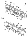
- Fig. 1 generally shows an electrical feedthrough in a spatial representation of a basic construction of a row leadthrough 102 with an inside view (protruding into the interior of the implant) and the outside.
- the electrical feedthrough comprises a flange 101, which preferably consists of Ti, Nb, Ta, Zr, alloys of one or more of the elements or further additional elements such as Hf, Al, Fe, P, Si, Mn or C, or of ceramic in which a plurality of bushing sleeves 106 are located, with which pins 103 are connected by solder joints.
- a soft solderable attachment 111 of the connecting pin 103 can be seen in the form of a disk, which is electrically and mechanically attached to the connecting pin 103 by a joint 112.
- the bushing is constructed in this and the following figures as a series bushing with a row of ten grommets 106 and connecting pins 103 and rows with four or six such grommets and connecting pins. In the latter there is additionally a ground pin 114, which likewise has a solderable attachment 11.
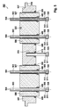
- Fig. 2 shows the section of another embodiment of the electrical feedthrough 202.
- the same or similar components are with Fig. 1 referred to reference numerals and will not be explained again here.
- reference numeral 102 in FIG Fig. 1 the same component as reference numeral 202 in FIG Fig. 2 ,
- the flange 201 preferably carries at least one cylindrical bushing 206 made of biocompatible Al 2 O 3 in its flange openings 207.
- Each of the bushings is soldered to the flange 201 with a solder joint 208 of biocompatible metallic brazing material.
- the bushings 206 are provided in this embodiment in the region of the flange openings 207 with a metallic coating, preferably biocompatible from Nb to make them wettable for brazing and thereby allow a soldering.
- the ceramic grommets 206 project beyond the flange 201 on both sides and ensure sufficiently long electrical insulation distances for high-voltage applications of the bushing 202.
- the connecting pin 203 preferably has a simple cylindrical shape, an outer end 204 and an inner end 205, and is connected by means of a solder joint 209 with the bushing 206 and thus fixed together with the grommet in the flange 201.
- Both the solder joint 208 and 209 are formed in the production phase as solder rings, which are located between the flange 201 and the grommets 206 and between grommets 206 and pins 203. By heating, for example via electrical resistance heating, electrical induction, heat conduction or infrared radiation, these rings are liquefied and form after cooling a biocompatible, mechanically stable, hermetically sealed, alternating temperature loadable solder joint.
- solder joints 208, 209 and joints 212 are added.
- the materials of the solder joints and the joint preferably consist of the same solder material, such as gold solders, gold niobium, gold tantalum, gold titanium, gold zirconium alloys. Alternatively, z.
- silver, copper-nickel, copper-zinc, copper-tin, silver-copper, silver-copper-zinc, silver-copper-zinc-tin, silver-copper-tin , Silver-copper-zinc-cadmium, copper-phosphorus, copper-phosphorus-silver, copper-gold alloys or numerous other alloys can be used to compensate for temperature inhomogeneities during the brazing process.
- These implant-internal joints must not be made biocompatible as well as the implant-inside pins, as they are hermetically sealed by the Implant housing and the hermetically sealed passage to the outside are separated.
- niobium for the pin 203 and 214 nickel for the weichlötbaren essay 211 and fine gold for brazing 212 and 215 chosen because fine gold produced with both niobium and nickel solder joints, the mixable in any alloy ratio and always form ductile phases.
- the resulting braze joints are so stable that, under mechanical stress, in most cases, the pins 203 and 214, respectively, will fail and not the braze joints 212.
- connection pin 203 and attachment 211 it is also technically advantageous in a first method step to add the joint 212 between the connection pin 203 and attachment 211 with a higher-melting brazing material or to weld directly without addition, in order subsequently to join these in a second brazing process with the other components of the implementation 202 so that possible problems - for example in complex and / or larger-scale structures - are avoided with unwanted temperature inhomogeneities. It is essential that no soft solder with tin content is used in the joint 212 in order to avoid mechanically unstable brittle phases between gold and tin.
- the electrical feedthrough according to the embodiment shown comprises a ground pin 214, for which they likewise apply the considerations relating to the soldered connections.
- the inner surfaces of the attachments 211 of the terminal pins 203 and the ground pin 214 are preferably all approximately in a common plane and thus allow a successful reflow soldering, but may also be in intentionally different levels, if it is the adaptation to the corresponding substrate of the implant requires.
- the flange 201 has a groove 217 for receiving the half-shells of an implant housing, not shown.
- a lip 218 serves as a welding protection during laser welding of the flange 201 with the housing halves of the implant.
- Fig. 3 shows a further variant of the embodiments Fig. 1 and Fig. 2 , Same or similar components are with Fig. 2 ajar reference numerals and will not be explained again here.
- the pins 304 according to the embodiment shown at the inner end 305 nailhead or plate-like approaches (also called “nailheads") 310 on. This facilitates better alignment of the solderable attachments 311 1 and achieves a more accurate common flatness.
- Fig. 4 shows a further or additional variant of the previously illustrated embodiments.
- the same or similar components are designated with reference to the previously described figures reference numerals and will not be explained again here.
- the solderable attachments 411 of the connection pins 403 and the ground pins 414 are at least on their end face with a coating or layer 430, preferably made of soft solder Sn37Pb z.
- a coating or layer 430 preferably made of soft solder Sn37Pb z.
- 411 suitable fluxes are used as auxiliaries, preferably of the standardized type "Alpha 850-33".
- fluxes such as aqueous or hydrochloric acid solutions of zinc chloride / Ammonium chloride, alcohol-based solutions with dimethylamine hydrochloride, or aqueous solutions of strongly activated halides are suitable. All these fluxes have the advantage that they are removed after the wetting of the attachments 411 with soft solder 430 in a simple cleaning process with aqueous solutions without residues from the implementation again and possible leakage paths in the implementation are not covered by flux residues, so that the bushings on safe manner, preferably with helium leak tests for hermeticity can be tested.
- the soft solder surface is additionally brought into a common plane by a special process, for example by thermal pretreatment or by grinding.
- the layers 430 of soft solder With the layers 430 of soft solder, a better common flatness is generally achieved than is possible with the attachments 411 alone, so that production-related unevennesses of the soft-solderable attachments 411 are compensated with the layer. Furthermore, the coating creates favorable conditions for a reflow soldering process, since it is no longer necessary to achieve as complete as possible wetting of the attachments 411 with soft solder during reflow soldering, since the surfaces the essays 411 are already wetted almost completely with soft solder. The side surfaces of the disc-shaped attachments 411 may also be wetted by the soft solder layer 430.
- the Au-Sn brittle phases are not disadvantageous in this arrangement, since the Au-Sn brittle phases do not function mechanically take over, mechanically not appreciably burdened and with the rest of the soft solder layer 430 are ductile contiguous, so that no components or particles of soft solder 430 replace the further application of the implementation.
- the inner ends 405 of the terminal pin 403 or the ground pin 414 may also, as in Fig. 3 shown to be nailhead-shaped.
- both the grommets 406 and the inner walls of the openings 407 of the flange 401 advantageously have corresponding bevels or steps 428 and 429.
- a tapered sleeve outer surface 426 is formed, which generally protrudes farther out of the flange 401 than without tapering to ensure a sufficient isolation distance.
- Fig. 5 shows a further, compatible to the previous embodiments variant in which two or more pins 503 may be soldered in a common ceramic 506.
- the same or similar components are designated with reference to the previously described figures reference numerals and will not be explained again here.
- the common ceramics 506 may have recesses or so-called "slots" 535 which extend the electrical isolation distances between the pins 503 with each other and / or the pins 503 and the flange 501 and thereby increase the high-voltage strength of the bushing.
- the soft solderable attachments 511 are provided with a particularly readily solderable coating 530, for example of palladium, silver, gold, copper or alloys of these materials.
- the coated attachments 511 are preferably punched out of double-coated Ni sheets or foils and are therefore preferably provided only on one end face with particularly good solderable coatings 530 for the subsequent reflow process.
- the coating 530 and the other coating facing the pin where the joint 512 may be made of different materials and have different thicknesses, with the other coating facing the pin being particularly suitable for brazing with the pins 503 and the ground pin 514 and the other reflow solder coating 530.
- the essays 511 may also have particularly good weichlötbare coatings on their lateral surfaces, which provide in this case for improved mechanical strength of the solder solder joints produced during reflow soldering.
- the flange 501 has a fitting 537, which serves for welding into an opening of the implant housing, not shown.
- a stop or a lip 518 simultaneously serves as a welding protection during laser welding of the flange 501 to the housing or the housing half shells of the implant.
- FIG. 6 A particular embodiment is in Fig. 6 shown.
- the same or similar components are designated with reference to the previously described figures reference numerals and will not be explained again here.
- an inner grommet 606 and an outer grommet 636 are mounted which form a cavity with the flange 601.
- the connecting pins 603 are soldered by means of a preferably biocompatible glass solder 609 with the flange 601 and the grommets 606 and 636, wherein the glass solder is in the cavity and this completely or almost completely fills.
- the grommets 606 and 636 form a flow barrier to the solder glass 609 during soldering, ie they prevent the glass solder 609 from flowing out of the openings 607 of the flange 601 during the soldering process.
- the ground pin 614 can be soldered by means of braze 613 in the opening 619 of the flange 601 as well as the attachments 611 by means of the joints 612, since glass solder generally allows a wide temperature range of processing.
- the solder joint 609 is preferably made of a biocompatible glass solder which simultaneously wets the flange 601, the terminal pins 603 and the grommets 606 and 636, and its thermal expansion coefficient is preferably matched to the wetted components.
- the grommets 606 and / or 636 may be omitted at the same time, if appropriate materials or combinations of materials for the flange, the pins and the glass solder are selected.
- the glass solder is less oxidizing or even reducing in composition, so that the metal surfaces for the glass solder are less attractive, the surface tension of the glass solder in the brazing dominates, and ultimately the glass, despite its low viscosity during processing, is not Outlets 607 flows out.
- These variants have the advantage that the soldering can be performed in total space-saving than at the same time with two grommets.
- the openings 607 may in other variants bevels or steps as in Fig. 4 described possess, which form a positioning aid in the openings 607 for the glass solder.
- Fig. 7 shows a further embodiment of the invention.
- a filtered conduit 702 is shown having a flange 701 having an inner bushing 706, an outer bushing 736, and a glass solder plug 709 therebetween.
- a pin defined by the Glaslotpfropf 709 is shown, which is made in two parts. It consists of an outer, biocompatible section 703, to which at a joint 712 a weichlötbarer pin 711 1 is added.
- the solder material of the joint 712 may be one of the aforementioned solder materials.
- the joint 712 may be defined by the glass solder plug during the manufacturing process so that it is located within the inner bushing 706 so as to be protected against mechanical and chemical influences.
- the electrical leadthrough comprises a ground pin 714, which in this embodiment variant is electrically and mechanically connected to the flange 701 by means of a weld 751.
- the ground pin may be made of the same biocompatible material as the biocompatible portion 703 of the terminal pin, but also the same material that makes up the flange 701, which improves weldability. however, includes a soft solderable portion 716 in the form of a disk.
- Both the soft solderable pins 711 and the soft solderable section 714 of the ground pin can be provided with a soft solder coating 730 for better bonding and form a common zone for the reflow process by a special thermal process or by grinding .
- a filter capacitor 757 is used in this variant, which is held by means of a sleeve 753 on the flange.
- the sleeve 753 is electrically and mechanically attached to the flange 701 by means of one or more welding points or seams 751, wherein the flange 701 may have a recess for better positioning of the sleeve 753 with respect to the flange 701.
- the weld points 751 are designed so that between the sleeve 753 and the flange 701 a leak test connection is created.
- the filter capacitor 757 comprises plate-shaped electrodes 756 and 758 which are embedded in a dielectric 757, which consists for example of barium titanate.
- the electrodes 756 have on the outside of the capacitor on a weichlötbare metallization 755 of, for example, palladium, silver, copper or their alloys. An electrical and mechanical ground connection is made to this metallization via a fixed solder connection 754 with the sleeve 753 fastened to the flange 701.
- the electrodes 758 are likewise provided with a solderable metallization 765 likewise made of palladium, silver, copper or their alloys at the openings of the capacitor, through which the soft solderable pins 711 extend and are soldered by means of the solder connection 764 to the soft solderable pins 711 in order to form the electrical connections to the electrical signals of the electrical implant.
- the solder joints 764 and 754 may consist of different types of soft solder with different melting points or ranges for reasons of better manufacturing.
- a material composition is preferably selected, for example PbSn3.5Ag1.5, which has a higher processing temperature with a soldering range of 305 ° C than the material of the solder joint 764 with the preferred material composition of, for example, PbSn5Ag2.5 and a Soldering temperature of 280 ° C.
- the capacitor 757 may first be soldered to the soft solderable sleeve 753 with the higher melting soft solder 754, the sleeve 753 with the soldered capacitor 757 placed over the pins 711 and electrically and mechanically attached to the flange 701 by means of welds 750 and finally soldered to the soft solderable pins 711 by means of a lower melting solder 764 without causing the higher melting solder 754 to melt again during the second soldering with the soft solder 764 and to dissolve the metallization 755 while losing the electrical / mechanical connection to the capacitor electrodes 756.
- the electrical feedthrough thus produced can be tested for hermeticity between the inside and outside of the implant by means of a helium leak test, since the leak test connection limits passage to the flange 701, sleeve 753, capacitor 757 and the individual inner feedthrough sleeves 706 and soft solderable pins 711 Cavity 752 creates through which the helium can flow.
- a single capacitor 757 instead of a single capacitor 757, multiple independent capacitors may also be used. It is also possible to filter only individual pins by means of capacitors 757 (for example for an antenna connection for the wireless transmission of signals out of the implant).
- the electrical and mechanical connection of the capacitor 757 can also be realized by means of electrically conductive adhesives, by means of welding, clamping or plugging, whereby a particular value is always placed on the leak testability of the arrangement.
- the leak testability may alternatively or additionally be realized by additional openings (not shown) in the capacitor 757, in the solders 754 and 764 and / or in the sleeve 753.
- the flange 701 may alternatively be shaped so that instead of the sleeve 753, the flange continues in a similar location and receives the capacitor 757 and has an additional opening in the resulting, not shown, wall to the cavity 752 for leak testability.
Landscapes
- Health & Medical Sciences (AREA)
- Engineering & Computer Science (AREA)
- Biomedical Technology (AREA)
- Nuclear Medicine, Radiotherapy & Molecular Imaging (AREA)
- Radiology & Medical Imaging (AREA)
- Life Sciences & Earth Sciences (AREA)
- Animal Behavior & Ethology (AREA)
- General Health & Medical Sciences (AREA)
- Public Health (AREA)
- Veterinary Medicine (AREA)
- Electrotherapy Devices (AREA)
- Prostheses (AREA)
Applications Claiming Priority (1)
| Application Number | Priority Date | Filing Date | Title |
|---|---|---|---|
| US31840510P | 2010-03-29 | 2010-03-29 |
Publications (3)
| Publication Number | Publication Date |
|---|---|
| EP2371418A2 true EP2371418A2 (fr) | 2011-10-05 |
| EP2371418A3 EP2371418A3 (fr) | 2014-09-24 |
| EP2371418B1 EP2371418B1 (fr) | 2021-11-03 |
Family
ID=44287327
Family Applications (1)
| Application Number | Title | Priority Date | Filing Date |
|---|---|---|---|
| EP11156793.9A Active EP2371418B1 (fr) | 2010-03-29 | 2011-03-03 | Conduite électrique pour implants électromédicaux |
Country Status (2)
| Country | Link |
|---|---|
| US (1) | US8536468B2 (fr) |
| EP (1) | EP2371418B1 (fr) |
Cited By (7)
| Publication number | Priority date | Publication date | Assignee | Title |
|---|---|---|---|---|
| EP2965783A1 (fr) | 2014-07-07 | 2016-01-13 | BIOTRONIK SE & Co. KG | Procede de fabrication d'une tige pour une conduite d'un implant electromedical et conduite |
| EP3181194A1 (fr) | 2015-12-15 | 2017-06-21 | BIOTRONIK SE & Co. KG | Réalisation d'un appareil médical électronique, son procédé de production et appareil médical électronique |
| EP3332836A1 (fr) | 2016-12-09 | 2018-06-13 | BIOTRONIK SE & Co. KG | Réalisation d'un appareil médical électronique implantable |
| EP3384958A1 (fr) * | 2017-04-03 | 2018-10-10 | BIOTRONIK SE & Co. KG | Traversée pour éléments d'implants |
| EP3461533A1 (fr) | 2017-09-29 | 2019-04-03 | BIOTRONIK SE & Co. KG | Partie du boitier extérieur d'un appareil médical électronique implantable |
| EP3939730A1 (fr) | 2020-07-14 | 2022-01-19 | BIOTRONIK SE & Co. KG | Méthode d'assemblage d'un premier et d'un deuxième composants d'une traversée utilisant un système réactif multicouche |
| US11806542B2 (en) | 2020-02-11 | 2023-11-07 | Inspire Medical Systems, Inc. | Feedthrough mounting for an electronic device, such as an implantable medical device, and methods of making the same |
Families Citing this family (29)
| Publication number | Priority date | Publication date | Assignee | Title |
|---|---|---|---|---|
| DE102009035972B4 (de) | 2009-08-04 | 2011-11-17 | W.C. Heraeus Gmbh | Cermethaltige Durchführung für eine medizinisch implantierbare Vorrichtung |
| DE102009035971B4 (de) * | 2009-08-04 | 2013-01-17 | Heraeus Precious Metals Gmbh & Co. Kg | Elektrische Durchführung für eine medizinisch implantierbare Vorrichtung |
| DE102010006689B4 (de) | 2010-02-02 | 2013-04-18 | Heraeus Precious Metals Gmbh & Co. Kg | Verfahren zum Herstellen einer elektrischen Durchführung, elektrische Durchführung sowie implantierbare Vorrichtung |
| DE102010006690B4 (de) | 2010-02-02 | 2013-03-28 | Heraeus Precious Metals Gmbh & Co. Kg | Verfahren zum Herstellen einer elektrischen Durchführung, elektrische Durchführung sowie implantierbare Vorrichtung |
| US20130058004A1 (en) * | 2011-09-01 | 2013-03-07 | Medtronic, Inc. | Feedthrough assembly including underfill access channel and electrically insulating material |
| US10881867B2 (en) | 2012-01-16 | 2021-01-05 | Greatbatch Ltd. | Method for providing a hermetically sealed feedthrough with co-fired filled via for an active implantable medical device |
| US9889306B2 (en) | 2012-01-16 | 2018-02-13 | Greatbatch Ltd. | Hermetically sealed feedthrough with co-fired filled via and conductive insert for an active implantable medical device |
| EP3366348B1 (fr) * | 2012-01-16 | 2023-08-23 | Greatbatch Ltd. | Traversée hermétique co-connectée filtrée emi, condensateur de traversée et ensemble de dérivation pour dispositif médical implantable actif |
| US20150250386A1 (en) * | 2012-09-28 | 2015-09-10 | Csem Centre Suisse D'electronique Et De Microtechnique Sa -Recherche Et Developpement | Implantable devices |
| US9478959B2 (en) | 2013-03-14 | 2016-10-25 | Heraeus Deutschland GmbH & Co. KG | Laser welding a feedthrough |
| US9431801B2 (en) | 2013-05-24 | 2016-08-30 | Heraeus Deutschland GmbH & Co. KG | Method of coupling a feedthrough assembly for an implantable medical device |
| US9403023B2 (en) | 2013-08-07 | 2016-08-02 | Heraeus Deutschland GmbH & Co. KG | Method of forming feedthrough with integrated brazeless ferrule |
| US9610452B2 (en) | 2013-12-12 | 2017-04-04 | Heraeus Deutschland GmbH & Co. KG | Direct integration of feedthrough to implantable medical device housing by sintering |
| US9504841B2 (en) | 2013-12-12 | 2016-11-29 | Heraeus Deutschland GmbH & Co. KG | Direct integration of feedthrough to implantable medical device housing with ultrasonic welding |
| US9610451B2 (en) | 2013-12-12 | 2017-04-04 | Heraeus Deutschland GmbH & Co. KG | Direct integration of feedthrough to implantable medical device housing using a gold alloy |
| DE102014216765A1 (de) * | 2014-08-22 | 2016-02-25 | Zf Friedrichshafen Ag | Mediendichtes Gehäuse |
| US9735477B2 (en) | 2014-10-14 | 2017-08-15 | Biotronik Se & Co. Kg | Terminal pin, feedthrough of an implantable electromedical device and process for making the same |
| DE102015208877B4 (de) * | 2014-11-19 | 2024-02-29 | Vitesco Technologies Germany Gmbh | Elektronische Komponente |
| EP3069760B1 (fr) * | 2015-03-20 | 2020-04-29 | BIOTRONIK SE & Co. KG | Dispositif electromedical implantable |
| US9985372B2 (en) * | 2015-03-20 | 2018-05-29 | BIOTRONIK SE Co. KG | Terminal pin and feedthrough |
| KR101656723B1 (ko) * | 2015-06-30 | 2016-09-12 | 재단법인 오송첨단의료산업진흥재단 | 피드스루 제조방법 |
| US10741223B2 (en) * | 2016-06-06 | 2020-08-11 | Western Digital Technologies, Inc. | Sealed bulkhead electrical feed-through positioning control |
| JP2018005960A (ja) * | 2016-07-01 | 2018-01-11 | エヌイーシー ショット コンポーネンツ株式会社 | 接触子を有する気密端子 |
| EP3311883B1 (fr) * | 2016-10-21 | 2020-01-29 | BIOTRONIK SE & Co. KG | Broche de raccordement et traversée |
| EP4226968B1 (fr) | 2020-02-21 | 2025-04-30 | Heraeus Medical Components, LLC | Ferrule pour boîtier de dispositif médical non planaire |
| EP4230258B1 (fr) | 2020-02-21 | 2025-06-04 | Heraeus Medical Components, LLC | Ferrule dotée d'une entretoise de réduction des contraintes pour dispositif médical implantable |
| IT202000017554A1 (it) * | 2020-07-20 | 2022-01-20 | Thales Alenia Space Italia Spa Con Unico Socio | Feedthrough capacitivo per moduli ermetici ibridi |
| US12409330B2 (en) * | 2020-08-27 | 2025-09-09 | Wiwynn Corporation | Airtight device and feedthrough module |
| US12176127B2 (en) * | 2022-12-12 | 2024-12-24 | Wyss Center For Bio And Neuro Engineering | Feedthrough for a medical device |
Citations (1)
| Publication number | Priority date | Publication date | Assignee | Title |
|---|---|---|---|---|
| US5870272A (en) | 1997-05-06 | 1999-02-09 | Medtronic Inc. | Capacitive filter feedthrough for implantable medical device |
Family Cites Families (11)
| Publication number | Priority date | Publication date | Assignee | Title |
|---|---|---|---|---|
| US5751539A (en) * | 1996-04-30 | 1998-05-12 | Maxwell Laboratories, Inc. | EMI filter for human implantable heart defibrillators and pacemakers |
| US5905627A (en) * | 1997-09-10 | 1999-05-18 | Maxwell Energy Products, Inc. | Internally grounded feedthrough filter capacitor |
| US6414835B1 (en) * | 2000-03-01 | 2002-07-02 | Medtronic, Inc. | Capacitive filtered feedthrough array for an implantable medical device |
| US6529103B1 (en) * | 2000-09-07 | 2003-03-04 | Greatbatch-Sierra, Inc. | Internally grounded feedthrough filter capacitor with improved ground plane design for human implant and other applications |
| EP1488434B1 (fr) * | 2002-02-28 | 2012-12-12 | Greatbatch Ltd. | Ensemble borne de filtrage de passage anti-interference electromagnetique pour fixation electrique entre fils de sortie et condensateur |
| US7038900B2 (en) * | 2003-02-27 | 2006-05-02 | Greatbatch-Sierra, Inc. | EMI filter terminal assembly with wire bond pads for human implant applications |
| US6768629B1 (en) * | 2003-06-02 | 2004-07-27 | Greatbatch-Hittman, Inc. | Multipin feedthrough containing a ground pin passing through an insulator and directly brazed to a ferrule |
| US6903268B2 (en) * | 2003-10-29 | 2005-06-07 | Medtronic, Inc. | Implantable device feedthrough assembly |
| US7035077B2 (en) * | 2004-05-10 | 2006-04-25 | Greatbatch-Sierra, Inc. | Device to protect an active implantable medical device feedthrough capacitor from stray laser weld strikes, and related manufacturing process |
| EP1945297B1 (fr) * | 2005-11-11 | 2016-08-10 | Greatbatch Ltd. | Filtres tank montés en série avec les fils conducteurs ou les circuits de dispositifs médicaux actifs, et en améliorant la compatibilité avec l'irm |
| US8326425B2 (en) * | 2006-03-30 | 2012-12-04 | Cardiac Pacemakers, Inc. | Feedthrough connector for implantable device |
-
2011
- 2011-03-03 EP EP11156793.9A patent/EP2371418B1/fr active Active
- 2011-03-09 US US13/043,886 patent/US8536468B2/en active Active
Patent Citations (1)
| Publication number | Priority date | Publication date | Assignee | Title |
|---|---|---|---|---|
| US5870272A (en) | 1997-05-06 | 1999-02-09 | Medtronic Inc. | Capacitive filter feedthrough for implantable medical device |
Cited By (12)
| Publication number | Priority date | Publication date | Assignee | Title |
|---|---|---|---|---|
| EP2965783A1 (fr) | 2014-07-07 | 2016-01-13 | BIOTRONIK SE & Co. KG | Procede de fabrication d'une tige pour une conduite d'un implant electromedical et conduite |
| US9821395B2 (en) | 2014-07-07 | 2017-11-21 | Biotronik Se & Co. Kg | Method for producing a pin for a feedthrough of an electromedical implant and a feedthrough |
| EP3181194A1 (fr) | 2015-12-15 | 2017-06-21 | BIOTRONIK SE & Co. KG | Réalisation d'un appareil médical électronique, son procédé de production et appareil médical électronique |
| DE102015121818A1 (de) | 2015-12-15 | 2017-06-22 | Biotronik Se & Co. Kg | Durchführung eines medizinelektronischen Geräts, Verfahren zur Herstellung einer solchen und medizinelektronisches Gerät |
| EP3332836A1 (fr) | 2016-12-09 | 2018-06-13 | BIOTRONIK SE & Co. KG | Réalisation d'un appareil médical électronique implantable |
| US10857367B2 (en) | 2016-12-09 | 2020-12-08 | Biotronik Se & Co. Kg | Feedthrough of an implantable medical electronic device |
| EP3384958A1 (fr) * | 2017-04-03 | 2018-10-10 | BIOTRONIK SE & Co. KG | Traversée pour éléments d'implants |
| EP3461533A1 (fr) | 2017-09-29 | 2019-04-03 | BIOTRONIK SE & Co. KG | Partie du boitier extérieur d'un appareil médical électronique implantable |
| EP3461534A1 (fr) * | 2017-09-29 | 2019-04-03 | BIOTRONIK SE & Co. KG | Partie du boitier extérieur d'un appareil médical électronique implantable |
| US11129995B2 (en) | 2017-09-29 | 2021-09-28 | Biotronik Se & Co. Kg | Outer casing part of an implantable medical electronic device |
| US11806542B2 (en) | 2020-02-11 | 2023-11-07 | Inspire Medical Systems, Inc. | Feedthrough mounting for an electronic device, such as an implantable medical device, and methods of making the same |
| EP3939730A1 (fr) | 2020-07-14 | 2022-01-19 | BIOTRONIK SE & Co. KG | Méthode d'assemblage d'un premier et d'un deuxième composants d'une traversée utilisant un système réactif multicouche |
Also Published As
| Publication number | Publication date |
|---|---|
| US20110232961A1 (en) | 2011-09-29 |
| US8536468B2 (en) | 2013-09-17 |
| EP2371418B1 (fr) | 2021-11-03 |
| EP2371418A3 (fr) | 2014-09-24 |
Similar Documents
| Publication | Publication Date | Title |
|---|---|---|
| EP2371418B1 (fr) | Conduite électrique pour implants électromédicaux | |
| US10589107B2 (en) | Circuit board mounted filtered feedthrough assembly having a composite conductive lead for an AIMD | |
| DE19819797C2 (de) | Durchführungsbaugruppe für eine implantierbare medizinische Vorrichtung | |
| EP1897588B1 (fr) | Conducteurs tranversants | |
| EP2371417B1 (fr) | Conduite électrique, procédé de fabrication et d'utilisation de celle-ci | |
| DE102011009866B4 (de) | Direkt aufbringbare elektrische Durchführung | |
| DE60005118T2 (de) | Durchführvorrichtungen | |
| DE10059373B4 (de) | Lecktestgeeignete, kapazitiv gefilterte Durchführung für ein implantierbares medizinisches Gerät | |
| EP1897589A2 (fr) | Passage électrique | |
| EP1923099A1 (fr) | Passage de filtre pour implants | |
| US20180178016A1 (en) | Hermetic terminal for an aimd having a pin joint in a feedthrough capacitor or circuit board | |
| EP2371419A2 (fr) | Conduite électrique d'un condensateur pour implants médicaux et procédé de fabrication et d'utilisation de celle-ci | |
| EP2926864A1 (fr) | Passage électrique pour implants électromédicaux, élément de contact électrique doté d'un tel passage et implant électromédical | |
| EP3072553B1 (fr) | Broche de raccordement et traversée | |
| EP3069757A1 (fr) | Realisation d'un appareil electronique medical implantable et appareil electronique medical implantable | |
| EP3332836B1 (fr) | Traversée d'un appareil médical électronique implantable | |
| EP3069760B1 (fr) | Dispositif electromedical implantable | |
| EP3181194A1 (fr) | Réalisation d'un appareil médical électronique, son procédé de production et appareil médical électronique | |
| EP3069756A1 (fr) | Realisation d'un appareil electronique medical implantable, procede de fabrication d'un tel appareil et appareil electronique medical implantable | |
| EP3311883B1 (fr) | Broche de raccordement et traversée | |
| EP3200568B1 (fr) | Élément de liaison pour batterie et procédé d'activation d'un dispositif électronique | |
| EP3069759A1 (fr) | Appareil electro-medical implantable avec une traversée ayant un corps de base monobloc en polymère | |
| DE102016107414A1 (de) | Durchführung eines implantierbaren medizinelektronischen Gerätes und implantierbares medizinelektronisches Gerät | |
| EP3939730A1 (fr) | Méthode d'assemblage d'un premier et d'un deuxième composants d'une traversée utilisant un système réactif multicouche | |
| DE102019218866A1 (de) | Verfahren zum Fügen mindestens eines ersten und eines zweiten Fügebereichs, Fügeverbindung und elektronische Komponente sowie Schaltungsanordnung |
Legal Events
| Date | Code | Title | Description |
|---|---|---|---|
| PUAI | Public reference made under article 153(3) epc to a published international application that has entered the european phase |
Free format text: ORIGINAL CODE: 0009012 |
|
| AK | Designated contracting states |
Kind code of ref document: A2 Designated state(s): AL AT BE BG CH CY CZ DE DK EE ES FI FR GB GR HR HU IE IS IT LI LT LU LV MC MK MT NL NO PL PT RO RS SE SI SK SM TR |
|
| AX | Request for extension of the european patent |
Extension state: BA ME |
|
| PUAL | Search report despatched |
Free format text: ORIGINAL CODE: 0009013 |
|
| AK | Designated contracting states |
Kind code of ref document: A3 Designated state(s): AL AT BE BG CH CY CZ DE DK EE ES FI FR GB GR HR HU IE IS IT LI LT LU LV MC MK MT NL NO PL PT RO RS SE SI SK SM TR |
|
| AX | Request for extension of the european patent |
Extension state: BA ME |
|
| RIC1 | Information provided on ipc code assigned before grant |
Ipc: A61N 1/375 20060101AFI20140818BHEP |
|
| 17P | Request for examination filed |
Effective date: 20150223 |
|
| RBV | Designated contracting states (corrected) |
Designated state(s): AL AT BE BG CH CY CZ DE DK EE ES FI FR GB GR HR HU IE IS IT LI LT LU LV MC MK MT NL NO PL PT RO RS SE SI SK SM TR |
|
| STAA | Information on the status of an ep patent application or granted ep patent |
Free format text: STATUS: EXAMINATION IS IN PROGRESS |
|
| 17Q | First examination report despatched |
Effective date: 20180417 |
|
| GRAP | Despatch of communication of intention to grant a patent |
Free format text: ORIGINAL CODE: EPIDOSNIGR1 |
|
| STAA | Information on the status of an ep patent application or granted ep patent |
Free format text: STATUS: GRANT OF PATENT IS INTENDED |
|
| INTG | Intention to grant announced |
Effective date: 20210527 |
|
| GRAS | Grant fee paid |
Free format text: ORIGINAL CODE: EPIDOSNIGR3 |
|
| GRAA | (expected) grant |
Free format text: ORIGINAL CODE: 0009210 |
|
| STAA | Information on the status of an ep patent application or granted ep patent |
Free format text: STATUS: THE PATENT HAS BEEN GRANTED |
|
| AK | Designated contracting states |
Kind code of ref document: B1 Designated state(s): AL AT BE BG CH CY CZ DE DK EE ES FI FR GB GR HR HU IE IS IT LI LT LU LV MC MK MT NL NO PL PT RO RS SE SI SK SM TR |
|
| REG | Reference to a national code |
Ref country code: GB Ref legal event code: FG4D Free format text: NOT ENGLISH |
|
| REG | Reference to a national code |
Ref country code: AT Ref legal event code: REF Ref document number: 1443429 Country of ref document: AT Kind code of ref document: T Effective date: 20211115 Ref country code: CH Ref legal event code: EP |
|
| REG | Reference to a national code |
Ref country code: IE Ref legal event code: FG4D Free format text: LANGUAGE OF EP DOCUMENT: GERMAN |
|
| REG | Reference to a national code |
Ref country code: DE Ref legal event code: R096 Ref document number: 502011017257 Country of ref document: DE |
|
| REG | Reference to a national code |
Ref country code: LT Ref legal event code: MG9D |
|
| REG | Reference to a national code |
Ref country code: NL Ref legal event code: MP Effective date: 20211103 |
|
| PG25 | Lapsed in a contracting state [announced via postgrant information from national office to epo] |
Ref country code: RS Free format text: LAPSE BECAUSE OF FAILURE TO SUBMIT A TRANSLATION OF THE DESCRIPTION OR TO PAY THE FEE WITHIN THE PRESCRIBED TIME-LIMIT Effective date: 20211103 Ref country code: LT Free format text: LAPSE BECAUSE OF FAILURE TO SUBMIT A TRANSLATION OF THE DESCRIPTION OR TO PAY THE FEE WITHIN THE PRESCRIBED TIME-LIMIT Effective date: 20211103 Ref country code: FI Free format text: LAPSE BECAUSE OF FAILURE TO SUBMIT A TRANSLATION OF THE DESCRIPTION OR TO PAY THE FEE WITHIN THE PRESCRIBED TIME-LIMIT Effective date: 20211103 Ref country code: BG Free format text: LAPSE BECAUSE OF FAILURE TO SUBMIT A TRANSLATION OF THE DESCRIPTION OR TO PAY THE FEE WITHIN THE PRESCRIBED TIME-LIMIT Effective date: 20220203 |
|
| PG25 | Lapsed in a contracting state [announced via postgrant information from national office to epo] |
Ref country code: IS Free format text: LAPSE BECAUSE OF FAILURE TO SUBMIT A TRANSLATION OF THE DESCRIPTION OR TO PAY THE FEE WITHIN THE PRESCRIBED TIME-LIMIT Effective date: 20220303 Ref country code: SE Free format text: LAPSE BECAUSE OF FAILURE TO SUBMIT A TRANSLATION OF THE DESCRIPTION OR TO PAY THE FEE WITHIN THE PRESCRIBED TIME-LIMIT Effective date: 20211103 Ref country code: PT Free format text: LAPSE BECAUSE OF FAILURE TO SUBMIT A TRANSLATION OF THE DESCRIPTION OR TO PAY THE FEE WITHIN THE PRESCRIBED TIME-LIMIT Effective date: 20220303 Ref country code: PL Free format text: LAPSE BECAUSE OF FAILURE TO SUBMIT A TRANSLATION OF THE DESCRIPTION OR TO PAY THE FEE WITHIN THE PRESCRIBED TIME-LIMIT Effective date: 20211103 Ref country code: NO Free format text: LAPSE BECAUSE OF FAILURE TO SUBMIT A TRANSLATION OF THE DESCRIPTION OR TO PAY THE FEE WITHIN THE PRESCRIBED TIME-LIMIT Effective date: 20220203 Ref country code: NL Free format text: LAPSE BECAUSE OF FAILURE TO SUBMIT A TRANSLATION OF THE DESCRIPTION OR TO PAY THE FEE WITHIN THE PRESCRIBED TIME-LIMIT Effective date: 20211103 Ref country code: LV Free format text: LAPSE BECAUSE OF FAILURE TO SUBMIT A TRANSLATION OF THE DESCRIPTION OR TO PAY THE FEE WITHIN THE PRESCRIBED TIME-LIMIT Effective date: 20211103 Ref country code: HR Free format text: LAPSE BECAUSE OF FAILURE TO SUBMIT A TRANSLATION OF THE DESCRIPTION OR TO PAY THE FEE WITHIN THE PRESCRIBED TIME-LIMIT Effective date: 20211103 Ref country code: GR Free format text: LAPSE BECAUSE OF FAILURE TO SUBMIT A TRANSLATION OF THE DESCRIPTION OR TO PAY THE FEE WITHIN THE PRESCRIBED TIME-LIMIT Effective date: 20220204 Ref country code: ES Free format text: LAPSE BECAUSE OF FAILURE TO SUBMIT A TRANSLATION OF THE DESCRIPTION OR TO PAY THE FEE WITHIN THE PRESCRIBED TIME-LIMIT Effective date: 20211103 |
|
| PG25 | Lapsed in a contracting state [announced via postgrant information from national office to epo] |
Ref country code: SM Free format text: LAPSE BECAUSE OF FAILURE TO SUBMIT A TRANSLATION OF THE DESCRIPTION OR TO PAY THE FEE WITHIN THE PRESCRIBED TIME-LIMIT Effective date: 20211103 Ref country code: SK Free format text: LAPSE BECAUSE OF FAILURE TO SUBMIT A TRANSLATION OF THE DESCRIPTION OR TO PAY THE FEE WITHIN THE PRESCRIBED TIME-LIMIT Effective date: 20211103 Ref country code: RO Free format text: LAPSE BECAUSE OF FAILURE TO SUBMIT A TRANSLATION OF THE DESCRIPTION OR TO PAY THE FEE WITHIN THE PRESCRIBED TIME-LIMIT Effective date: 20211103 Ref country code: EE Free format text: LAPSE BECAUSE OF FAILURE TO SUBMIT A TRANSLATION OF THE DESCRIPTION OR TO PAY THE FEE WITHIN THE PRESCRIBED TIME-LIMIT Effective date: 20211103 Ref country code: DK Free format text: LAPSE BECAUSE OF FAILURE TO SUBMIT A TRANSLATION OF THE DESCRIPTION OR TO PAY THE FEE WITHIN THE PRESCRIBED TIME-LIMIT Effective date: 20211103 Ref country code: CZ Free format text: LAPSE BECAUSE OF FAILURE TO SUBMIT A TRANSLATION OF THE DESCRIPTION OR TO PAY THE FEE WITHIN THE PRESCRIBED TIME-LIMIT Effective date: 20211103 |
|
| REG | Reference to a national code |
Ref country code: DE Ref legal event code: R097 Ref document number: 502011017257 Country of ref document: DE |
|
| PLBE | No opposition filed within time limit |
Free format text: ORIGINAL CODE: 0009261 |
|
| STAA | Information on the status of an ep patent application or granted ep patent |
Free format text: STATUS: NO OPPOSITION FILED WITHIN TIME LIMIT |
|
| 26N | No opposition filed |
Effective date: 20220804 |
|
| PG25 | Lapsed in a contracting state [announced via postgrant information from national office to epo] |
Ref country code: MC Free format text: LAPSE BECAUSE OF FAILURE TO SUBMIT A TRANSLATION OF THE DESCRIPTION OR TO PAY THE FEE WITHIN THE PRESCRIBED TIME-LIMIT Effective date: 20211103 Ref country code: AL Free format text: LAPSE BECAUSE OF FAILURE TO SUBMIT A TRANSLATION OF THE DESCRIPTION OR TO PAY THE FEE WITHIN THE PRESCRIBED TIME-LIMIT Effective date: 20211103 |
|
| GBPC | Gb: european patent ceased through non-payment of renewal fee |
Effective date: 20220303 |
|
| PG25 | Lapsed in a contracting state [announced via postgrant information from national office to epo] |
Ref country code: SI Free format text: LAPSE BECAUSE OF FAILURE TO SUBMIT A TRANSLATION OF THE DESCRIPTION OR TO PAY THE FEE WITHIN THE PRESCRIBED TIME-LIMIT Effective date: 20211103 |
|
| REG | Reference to a national code |
Ref country code: BE Ref legal event code: MM Effective date: 20220331 |
|
| PG25 | Lapsed in a contracting state [announced via postgrant information from national office to epo] |
Ref country code: LU Free format text: LAPSE BECAUSE OF NON-PAYMENT OF DUE FEES Effective date: 20220303 Ref country code: GB Free format text: LAPSE BECAUSE OF NON-PAYMENT OF DUE FEES Effective date: 20220303 Ref country code: FR Free format text: LAPSE BECAUSE OF NON-PAYMENT OF DUE FEES Effective date: 20220331 |
|
| PG25 | Lapsed in a contracting state [announced via postgrant information from national office to epo] |
Ref country code: BE Free format text: LAPSE BECAUSE OF NON-PAYMENT OF DUE FEES Effective date: 20220331 |
|
| REG | Reference to a national code |
Ref country code: AT Ref legal event code: MM01 Ref document number: 1443429 Country of ref document: AT Kind code of ref document: T Effective date: 20220303 |
|
| PG25 | Lapsed in a contracting state [announced via postgrant information from national office to epo] |
Ref country code: IT Free format text: LAPSE BECAUSE OF FAILURE TO SUBMIT A TRANSLATION OF THE DESCRIPTION OR TO PAY THE FEE WITHIN THE PRESCRIBED TIME-LIMIT Effective date: 20211103 |
|
| P01 | Opt-out of the competence of the unified patent court (upc) registered |
Effective date: 20230606 |
|
| PG25 | Lapsed in a contracting state [announced via postgrant information from national office to epo] |
Ref country code: AT Free format text: LAPSE BECAUSE OF NON-PAYMENT OF DUE FEES Effective date: 20220303 |
|
| PG25 | Lapsed in a contracting state [announced via postgrant information from national office to epo] |
Ref country code: HU Free format text: LAPSE BECAUSE OF FAILURE TO SUBMIT A TRANSLATION OF THE DESCRIPTION OR TO PAY THE FEE WITHIN THE PRESCRIBED TIME-LIMIT; INVALID AB INITIO Effective date: 20110303 |
|
| PGFP | Annual fee paid to national office [announced via postgrant information from national office to epo] |
Ref country code: IE Payment date: 20240319 Year of fee payment: 14 |
|
| PG25 | Lapsed in a contracting state [announced via postgrant information from national office to epo] |
Ref country code: MK Free format text: LAPSE BECAUSE OF FAILURE TO SUBMIT A TRANSLATION OF THE DESCRIPTION OR TO PAY THE FEE WITHIN THE PRESCRIBED TIME-LIMIT Effective date: 20211103 Ref country code: CY Free format text: LAPSE BECAUSE OF FAILURE TO SUBMIT A TRANSLATION OF THE DESCRIPTION OR TO PAY THE FEE WITHIN THE PRESCRIBED TIME-LIMIT Effective date: 20211103 |
|
| PGFP | Annual fee paid to national office [announced via postgrant information from national office to epo] |
Ref country code: DE Payment date: 20240321 Year of fee payment: 14 |
|
| PG25 | Lapsed in a contracting state [announced via postgrant information from national office to epo] |
Ref country code: TR Free format text: LAPSE BECAUSE OF FAILURE TO SUBMIT A TRANSLATION OF THE DESCRIPTION OR TO PAY THE FEE WITHIN THE PRESCRIBED TIME-LIMIT Effective date: 20211103 |
|
| PGFP | Annual fee paid to national office [announced via postgrant information from national office to epo] |
Ref country code: CH Payment date: 20240401 Year of fee payment: 14 |
|
| PG25 | Lapsed in a contracting state [announced via postgrant information from national office to epo] |
Ref country code: MT Free format text: LAPSE BECAUSE OF FAILURE TO SUBMIT A TRANSLATION OF THE DESCRIPTION OR TO PAY THE FEE WITHIN THE PRESCRIBED TIME-LIMIT Effective date: 20211103 |
|
| REG | Reference to a national code |
Ref country code: DE Ref legal event code: R119 Ref document number: 502011017257 Country of ref document: DE |
|
| REG | Reference to a national code |
Ref country code: CH Ref legal event code: H13 Free format text: ST27 STATUS EVENT CODE: U-0-0-H10-H13 (AS PROVIDED BY THE NATIONAL OFFICE) Effective date: 20251023 |
|
| PG25 | Lapsed in a contracting state [announced via postgrant information from national office to epo] |
Ref country code: DE Free format text: LAPSE BECAUSE OF NON-PAYMENT OF DUE FEES Effective date: 20251001 |
|
| PG25 | Lapsed in a contracting state [announced via postgrant information from national office to epo] |
Ref country code: CH Free format text: LAPSE BECAUSE OF NON-PAYMENT OF DUE FEES Effective date: 20250331 |
|
| PG25 | Lapsed in a contracting state [announced via postgrant information from national office to epo] |
Ref country code: IE Free format text: LAPSE BECAUSE OF NON-PAYMENT OF DUE FEES Effective date: 20250303 |