EP2371480A1 - Centre de traitement de profilés - Google Patents
Centre de traitement de profilés Download PDFInfo
- Publication number
- EP2371480A1 EP2371480A1 EP11153248A EP11153248A EP2371480A1 EP 2371480 A1 EP2371480 A1 EP 2371480A1 EP 11153248 A EP11153248 A EP 11153248A EP 11153248 A EP11153248 A EP 11153248A EP 2371480 A1 EP2371480 A1 EP 2371480A1
- Authority
- EP
- European Patent Office
- Prior art keywords
- profile
- roller
- machining center
- turntable
- rotation
- Prior art date
- Legal status (The legal status is an assumption and is not a legal conclusion. Google has not performed a legal analysis and makes no representation as to the accuracy of the status listed.)
- Granted
Links
Images



Classifications
-
- B—PERFORMING OPERATIONS; TRANSPORTING
- B23—MACHINE TOOLS; METAL-WORKING NOT OTHERWISE PROVIDED FOR
- B23Q—DETAILS, COMPONENTS, OR ACCESSORIES FOR MACHINE TOOLS, e.g. ARRANGEMENTS FOR COPYING OR CONTROLLING; MACHINE TOOLS IN GENERAL CHARACTERISED BY THE CONSTRUCTION OF PARTICULAR DETAILS OR COMPONENTS; COMBINATIONS OR ASSOCIATIONS OF METAL-WORKING MACHINES, NOT DIRECTED TO A PARTICULAR RESULT
- B23Q7/00—Arrangements for handling work specially combined with or arranged in, or specially adapted for use in connection with, machine tools, e.g. for conveying, loading, positioning, discharging, sorting
- B23Q7/05—Arrangements for handling work specially combined with or arranged in, or specially adapted for use in connection with, machine tools, e.g. for conveying, loading, positioning, discharging, sorting by means of roller-ways
-
- B—PERFORMING OPERATIONS; TRANSPORTING
- B23—MACHINE TOOLS; METAL-WORKING NOT OTHERWISE PROVIDED FOR
- B23Q—DETAILS, COMPONENTS, OR ACCESSORIES FOR MACHINE TOOLS, e.g. ARRANGEMENTS FOR COPYING OR CONTROLLING; MACHINE TOOLS IN GENERAL CHARACTERISED BY THE CONSTRUCTION OF PARTICULAR DETAILS OR COMPONENTS; COMBINATIONS OR ASSOCIATIONS OF METAL-WORKING MACHINES, NOT DIRECTED TO A PARTICULAR RESULT
- B23Q1/00—Members which are comprised in the general build-up of a form of machine, particularly relatively large fixed members
- B23Q1/01—Frames, beds, pillars or like members; Arrangement of ways
- B23Q1/015—Frames, beds, pillars
-
- B—PERFORMING OPERATIONS; TRANSPORTING
- B23—MACHINE TOOLS; METAL-WORKING NOT OTHERWISE PROVIDED FOR
- B23Q—DETAILS, COMPONENTS, OR ACCESSORIES FOR MACHINE TOOLS, e.g. ARRANGEMENTS FOR COPYING OR CONTROLLING; MACHINE TOOLS IN GENERAL CHARACTERISED BY THE CONSTRUCTION OF PARTICULAR DETAILS OR COMPONENTS; COMBINATIONS OR ASSOCIATIONS OF METAL-WORKING MACHINES, NOT DIRECTED TO A PARTICULAR RESULT
- B23Q39/00—Metal-working machines incorporating a plurality of sub-assemblies, each capable of performing a metal-working operation
- B23Q39/02—Metal-working machines incorporating a plurality of sub-assemblies, each capable of performing a metal-working operation the sub-assemblies being capable of being brought to act at a single operating station
- B23Q39/021—Metal-working machines incorporating a plurality of sub-assemblies, each capable of performing a metal-working operation the sub-assemblies being capable of being brought to act at a single operating station with a plurality of toolheads per workholder, whereby the toolhead is a main spindle, a multispindle, a revolver or the like
- B23Q39/025—Metal-working machines incorporating a plurality of sub-assemblies, each capable of performing a metal-working operation the sub-assemblies being capable of being brought to act at a single operating station with a plurality of toolheads per workholder, whereby the toolhead is a main spindle, a multispindle, a revolver or the like with different working directions of toolheads on same workholder
- B23Q39/026—Metal-working machines incorporating a plurality of sub-assemblies, each capable of performing a metal-working operation the sub-assemblies being capable of being brought to act at a single operating station with a plurality of toolheads per workholder, whereby the toolhead is a main spindle, a multispindle, a revolver or the like with different working directions of toolheads on same workholder simultaneous working of toolheads
Definitions
- the invention relates to a profile machining center with a turntable unit with a plurality of machining tools and at least one clamping device for clamping profiles.
- Turntable units enable many different machining operations on a single workstation.
- the flexibility of such turntable units is often limited in the profile machining that the profiles can not be clamped in any position, but either have to assume a certain position in which they can be firmly clamped without risk of damage or the clamping devices must be specially designed To hold a profile so that it is held on the one hand and on the other hand can not be damaged by the clamping forces.
- Such special clamping devices can, for example have specially manufactured fittings for certain profiles.
- Particularly critical in the processing are painted or coated profiles or profiles that have freely projecting and bend-sensitive leg.
- a profile machining center is to be improved with a turntable unit.
- a profile machining center is provided with a turntable unit with a plurality of machining tools and at least one clamping device for clamping profiles, wherein a profile to be machined arranged within the turntable and fixed by means of the clamping device, wherein the clamping device at least one support roller with horizontally arranged, relatively to the machine frame immovable axis of rotation, in which the clamping device has at least a first tensioning roller with horizontally arranged axis of rotation and at least a second tensioning roller with vertically arranged axis of rotation, wherein the first tensioning roller is displaceable relative to the machine frame both in the horizontal and in the vertical direction and the second tensioning roller is displaceable relative to the machine frame at least in the horizontal direction and wherein the clamping device comprises a control unit to the first and / or the second tensioning roller optionally to move in a predefined set position and / or apply by means of the first and / or second tension roller a predefined set clamping force on a profile to
- the inventive design of the profile machining center it is possible to hold a profile to be machined substantially in any position and without risk of damage.
- Sensitive parts of profiles for example freely projecting legs, can be held in such a way by means of the first or the second tensioning roller, that the first and / or the second tensioning roller is moved into a predefined setpoint position and consequently forms a stop for the profile without applying too great a clamping force, which could possibly cause damage to the profile.
- the other tensioning roller or other tensioning rollers can be moved against insensitive sections of the profile with a predefined set clamping force in order to keep the profile safe for machining.
- first tensioning roller is displaceable relative to the machine frame in both the horizontal and in the vertical direction and the second tensioning roller is displaceable relative to the machine frame at least in the horizontal direction, a variety of profiles for machining can be kept safe.
- profile machining center according to the invention, it is thereby possible to securely hold various profiles in substantially any position on the support rollers and thereby fully exploit the flexibility of the turntable unit.
- the support rollers define a support plane below a rotation axis of the turntable.
- At least one side stop roller with a vertically arranged axis of rotation is provided.
- the at least one is an immovable to the machine frame axis of rotation and defines a vertical stop plane, which is arranged offset in the horizontal direction to the axis of rotation of the turntable.
- the at least one soanschlagrolle is displaced in the horizontal direction.
- the flexibility of the profile machining center according to the invention is further increased, for example, for profiles with large cross-section, the vertical stop plane is further offset against the axis of rotation of the turntable or vice versa for small profiles, the vertical stop level is moved closer to the axis of rotation of the turntable.
- the tension roller and / or the side stop roller are rotatably mounted on a bearing block, wherein the bearing block has at least one outlet opening for compressed air in the region of the outer circumference of the tension roller or soanschlagrolle.
- first tensioning roller and the second tensioning roller are displaceably arranged by means of a respective carriage on a horizontally extending rail.
- the space requirement and also the costs for the tensioning device can be kept low.
- the soanschlagrolle is arranged by means of a carriage on the horizontally extending rail.
- the first tensioning roller is arranged displaceably on a vertically extending rail by means of a carriage, wherein the vertically extending rail is fastened to a support arranged displaceably on the horizontally disposed rail.
- At least one horizontally and vertically displaceable first tensioning roller is seen in the transporting direction of a profile to be machined in front of and behind the slewing ring and in each case at least one horizontally displaceable tension roller provided with a vertically arranged axis of rotation.
- a profile can be reliably held in this way both before and behind the turntable.
- two horizontally and vertically displaceable first tension rollers are provided, wherein the two tension rollers are arranged on a carrier extending in the direction of transport, which extends in the direction of the turntable.
- the guide rails for the first tension rollers can be removed so far away from the plane of the turntable that there is enough space for the rotation of the turntable and arranged on the turntable processing units available.
- At least one horizontally and vertically displaceable first tensioning roller with a horizontally arranged axis of rotation is provided to the right and left of a rotation axis of the slewing ring.
- the first tension rollers can be approached both from the right and from the left to the profile to be machined. Even with complicated shaped profiles, in conjunction with the inventive option to move the first idlers either in a predefined set position or apply a predefined set clamping force with the tension rollers, even complex shaped and / or sensitive profiles can be reliably maintained for high-precision machining.
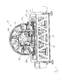
- the presentation of the Fig. 1 shows a profile machining center 10 according to the invention with a turntable unit 12 with a plurality of machining tools 14a, 14b, 14c.
- the processing tools 14a, 14b, 14c are designed as motors and can be provided with different tool inserts.
- a processing unit on the turntable for example, a saw may be provided, alternatively, a saw of the turntable unit 12 may be connected downstream.
- the turntable unit 12 is rotatably supported on a machine frame 16 which rests on a foundation. Means for feeding profiles to the turntable unit 12 and for discharging the processed profiles are not shown for clarity.
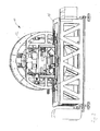
- a clamping device of the profile machining center 10 has, see the enlarged view of Fig. 2 , a total of six support rollers 18 with horizontally arranged axis of rotation.
- the axes of rotation of the support rollers 18 are arranged horizontally and fixed relative to the machine frame 16.
- a bearing block 20 which in turn is formed sled-shaped and slidably disposed on a horizontal rail 22.
- a side stop roller 24 is further rotatably arranged, the axis of rotation is arranged vertically.
- first tension rollers 26a, 26b, 26c, 26d, 26e, 26f and four second tension rollers 28a, 28b, 28c are provided with vertically arranged axes of rotation in the profile machining center.
- the first tension rollers 26a to 26f are each displaceable in the horizontal direction and in the vertical direction, the first tension rollers 26a, 26d in the illustration of FIG Fig. 1 and 2 are arranged in front of the turntable 12 and the first tension rollers 26b, 26c, 26e and 26f are arranged behind the turntable 12.
- the first tension rollers 26a, 26d are each disposed on a bearing block 30a, 30b, wherein the bearing blocks, 30a, 30b are each mounted on a carriage, which along a vertically arranged rail 32a, 32b is displaceable.
- the rails 32a, 32b are each disposed on a vertically extending support 34a, 34b, wherein the supports 34a, 34b are in turn connected at their respective lower end to a carriage, which is displaceable along the horizontal rail 22.
- the bearing blocks 30a, 30b can be displaced by means of an adjusting cylinder 36a, 36b along the respective vertical rail 32a, 32b.
- the vertical supports 34a, 34b can each be displaced in the horizontal direction on the rail 22 by means of an adjusting cylinder 38a, 38b.
- the second tension rollers 28a, 28b, 28c, 28d are each mounted on a bearing block 40a, 40b, wherein in the illustrations of the Fig. 1 and 2 only the bearing block 40a can be seen for the tension roller 28a, which in the Fig. 1 and 2 is arranged in front of the turntable 12.
- the bearing block 40a is connected to a carriage, which is arranged displaceably on the horizontally extending rail 22. In order to move the bearing block 40a and thus the second tension roller 28a in the horizontal direction, one in the representations of Fig. 1 and 2 not to be recognized adjusting cylinder provided.
- a profile to be machined is conveyed onto the slewing ring 12 on the support rollers 18 until the point of the profile to be machined is located within the turntable 12.
- the first tensioning rollers 26a to 26f and the second tensioning rollers 28a to 28c are delivered toward the profile, then the profile during machining between the support rollers 18 and the first tension rollers 26a to 26f as well to hold the side stop rollers 24 and the second tension rollers 28a to 28d.
- the adjusting cylinders of the first and second tensioning rollers can be controlled such that either the first and second tensioning rollers are moved into a predefined setpoint position or the first and second tension rollers exert a predefined set tension on the profile.
- the control signals required for this purpose are from an in Fig. 1 and 2 not shown, the control unit can also alternate in time between the different setting modes. For example, a profile is inserted into the processing area within the turntable 12 and then brought into a defined target position against the Soanschlagrollen 24 by moving the second tension rollers 28a to 28d.
- the defined target position of the second tension rollers 28a to 28d can initially be adjusted so that the profile is fixed only in its position, but no appreciable clamping force is applied to the profile. This can be useful, for example, to prevent tilting or turning away the profile during clamping.
- the first tension rollers 26a to 26f are moved against the top of the profile, for example so that the first tension rollers 26a to 26f have a predefined set tension force apply the profile.
- a turning away or tilting of the profile by applying the desired clamping force by means of the first tension rollers 26a to 26f is then prevented by the fact that the profile is already securely fixed between the soanschlagrollen 24 and the second tension rollers 26a-c.
- the control unit can still act on the adjusting cylinders of the second tensioning rollers 28a to 28d so that the second tensioning rollers 28a to 28d apply a predefined set clamping force to the profile and thereby the profile immovable for machining by the processing tools 14a, 14b, 14c on the turntable 12 hold.
- first tensioning rollers 26a to 26f and the second tensioning rollers 28a to 28d can each be moved by means of the control unit and the respectively associated adjusting cylinders in such a way that they are either moved into a predefined setpoint position or apply a predefined set clamping force on the profile, wherein the method can be carried out in a predefined set position during a single clamping operation before or after the application of a predefined set clamping force.
- the support rollers 18 define a support plane below the turntable 12 of the profile machining center 10.
- the free space within the turntable 12, which indeed defines the maximum dimensions of a profile to be processed, can be used as far as possible.
- the bearing blocks for the first tensioning rollers 26a to 26f and the bearing blocks 40a, 40b for the second tensioning rollers 28a to 28d are provided with outlet openings for compressed air in order to be able to blow off chips produced during machining from the machined profile.
- the outlet openings are arranged in the bearing blocks so that the compressed air emerges approximately axially to the first tension rollers 26a to 26f and the second tension rollers 28a to 28d.
- the presentation of the Fig. 3 shows the profile processing center 10 of Fig. 1 from the back, so from the Austransportseite a profile.
- a profile to be processed is therefore in the representation of Fig. 1 into the drawing plane and pushed through the turntable 12, in the plane of the Fig. 3 So out of the drawing level.
- first tension rollers 26a, 26b and behind the turntable 12 four first tension rollers 26c, 26d, 26e and 26f are arranged in the direction of movement of a profile to be machined through the turntable 12 before the turntable 12.
- the axes of rotation of the first tension rollers 26a to 26f are each arranged horizontally, and the first tension rollers 26a to 26f are displaceable both in the horizontal and in the vertical direction.
- the first tension rollers 26e, 26f, 26c, 26d arranged in the transport direction of a profile through the turntable 12 behind the turntable 12 are mounted in the same way as the first tension rollers 26a, 26b on a bearing block, which in turn is slidably mounted on a vertical rail.
- the vertical rail is arranged on a vertical support, which in turn is then slidably mounted on a common horizontal rail 44 by means of a carriage.
- the arrangement for the horizontal and vertical displacement of the first tension rollers 26e, 26f, 26c, 26d is the same as already described with reference to FIG Fig. 1 and 2 and the tension rollers 26a, 26b has been explained, so that dispenses with a new discussion.
- Each two first tension rollers 26e, 26f and 26c, 26d are arranged on a common bearing block 46, 48.
- the bearing blocks 46, 48 have an L-like shape, wherein a free leg extends in the direction of the turntable 12 and is arranged horizontally. In the region of the end of this free leg, in each case a first tension roller 26e or 26c is arranged.
- These tensioning rollers 26e, 26c can thereby tension a profile to be machined very close to the machining point in order to enable a high-precision machining.
- Fig. 4 As in the presentation of Fig. 4 can be seen, four support rollers 18 are arranged in the transport direction of a profile to be machined behind the turntable 12 and these four support rollers 18 are together with three soanschlagrollen 24 on a common bearing block 50 arranged.
- the bearing block 50 is slidably mounted on the common horizontal rail 44, wherein a displacement of the bearing block 50 and thus the support rollers 18 and the soanschlagrollen 24 only in the context of adjustments, but not during a tensioning operation.
- the total of six support rollers 18 are seen in the vertical direction, a total of six first tension rollers 26a to 26f opposite.
- the second tension rollers 26a to 26f are arranged so that each first tension roller 26a to 26f in the vertical direction of the support roller 18 is opposite. As a result, symmetrical clamping conditions are ensured even in the vertical direction.
- the first tension rollers 26c, 26d, 26e and 26f are arranged such that the first tension roller 26e is disposed between the two tension rollers 26c, 26d and the first tension roller 26f is then disposed behind the first tension roller 26d is. So if all six tension rollers 26a to 26f rest on top of the top of a profile, so the profile is seen in the direction of transport alternately held by a right and a left-mounted first tension pulley 26a to 26f.
- a clamped profile 60 which rests on the support rollers 18 and which is to be clamped between the Soantschrolle 24 and in the direction of the profile 60 to and away from this second tensioner pulley 28.
- the first tensioning roller 26 can still be moved from above onto the profile 60 toward and away from it.
- the two movable tension rollers 26, 28 are each provided with an actuator, not shown, which has a tension force sensor and a position sensor, wherein the actuators, as already stated, are controlled by a control unit.
- the profile 60 has a square cross-section and is uncritical with respect to the tension exerted by the rollers 18, 24, 26, 28 on the profile 60. It makes sense, the control unit but first the second tension roller 28 to move to the profile 60 until it rests with its back on the soanschlagrolle 24. Subsequently, the first tension roller 26 is delivered to press the profile 60 on the support roller 18. At the same time or subsequently, the actuators of the movable tensioning rollers 26, 28 can be regulated so that they reach an intended set clamping force.
- the second tensioning roller 28 is first moved by the control unit into a predefined setpoint position. In this nominal position, the second tensioning roller provides 28 ensures that the opposite side of the U-profile 70 rests against the side stop roller 24. Since the control unit knows the dimensions of the profile 70 and the side stop roller 24 and the support roller 18 define a zero position, the control unit can determine the desired position. It is essential, however, that the second tension roller 28 is moved in a position control, since no excessive force may be exerted on the U-profile 70.
- the control unit moves the first tension roller 26 on the profile 70 until a predefined set clamping force is reached.
- the first tension roller 26 is operated by means of a clamping force control, since the U-profile 70 is insensitive to a load from above and no major deformations are to be feared.
- the U-profile 70 is thus brought about the second tension roller 28 in the intended position, but only by the first tension roller 26 fixed so that it can be edited.
- the second tensioning pulley 28 can still be moved toward the U-profile 70 by regulating the tensioning force in order to apply a nominal tensioning force also by means of the second tensioning roller 28 , As long as the first tension roller 26 presses the U-profile 70 against the support roller 18, a higher clamping force can be applied to the U-profile 70 by means of the second tension pulley 28 without deformations are to be feared, as if the first tension roller 26, the U Profile 70 would not press against the support roller 18.
- FIG. 3 shows the tensioning of the U-profile 70 according to the prior art.
- Both tension rollers 26, 28 would be delivered in this case only with a clamping force control on the U-profile 70.
- the U-profile 70 would be compressed at the free ends of its legs and could not be edited.
- the prior art has been used to avoid such problems For example, used an intermediate piece, which was inserted into the U-profile 70 to prevent its deformation.
- the presentation of the Fig. 7a schematically shows the tensioning of another, unilaterally open profile 80.
- the cross section of the profile 80 can be described as approximately house-shaped, with a side wall of the house and a roof slope of the gable roof is omitted.
- the profile 80 can be seen against a load from above extremely sensitive to deformation.
- the second tensioning roller 28 is initially moved in the direction of the profile 80 in order to fix the profile 80 between the second tensioning roller 28 and the side stop roller 24.
- the second tension roller 28 can be operated either by means of position control or clamping force control, since the profile 80 relative to a load by the second tension roller 28 is relatively insensitive.
- the profile 80 is clamped with a predefined set clamping force.
- the first tension roller 26 is moved in the direction of the profile 80, wherein the first tension roller 26 is moved in the position control in a predefined target position.
- This target position is selected so that the first tension roller 26 presses only slightly on the free leg of the profile 80 and this additionally fixed.
- the fact that the first tension roller 26 is moved by means of a position control is not to be feared that the profile 80 is deformed by deficiencies in the clamping force control or by stick-shift effects of the actuator.
- the presentation of the Fig. 7b schematically shows the tensioning of the profile 38 according to the prior art.
- the first tension roller 26 is to move according to the prior art in a clamping force control on the profile 80.
- Stick-shift effects for example, caused by a comparatively high breakaway torque of the actuator of the first tension roller 26, cause the first tension roller 26 presses from above on the profile 80 and this deformed in an inadmissible manner.
- Fig. 8a shows the tensioning of another profile 90 in the profile machining center according to the invention.
- the profile 90 has two strips arranged parallel to one another, which are connected to one another by means of a bevel.
- the profile 90 is thus very difficult to clamp, since it will fall over solely by gravity and thereby, see Fig. 8c , Was arranged in a position in which none of the profile surfaces 90 parallel to the rollers 18, 24, 26, 28 would be arranged. Precise machining would be in the overturned position Fig. 8c impossible to accomplish.
- first the second tension roller 28 is to move in a position control to a designated target position on the profile 90.
- the profile 90 bears on the one hand with its back on the soanschlagrolle 24 and is held by means of the second tension roller 28 which engages the slope of the profile 90, reliably in its upright position. Since the second tensioning roller 28 has been moved to a desired position, there is no fear that the second tensioning roller 28 pushes up the profile 90, so that its in the Fig. 8a Left edge strip no longer horizontally rests on the support roller 18.
- the first tension roller 26 can be placed on the profile 90 to. Also, the first tension roller 26 is thereby moved by means of a position control in a designated target position, so that the profile 90 is not deformed by an excessive clamping force of the first tension roller 26.
- Fig. 8b shows the problems that occur when clamping the profile 90 according to the prior art.
- the second tension roller 28 was delivered to the profile 90 until reaching a predetermined clamping force.
- the profile 90 is pushed up and comes to lie outside the processing area after the feed of the first tensioning roller 26.
- Fig. 8c At first, the first tensioning roller 26 was placed on the profile 90 up to a predetermined tension force. This initially causes the profile 90 to tip over and come to rest on the support roller 18, that none of its surfaces is more parallel to the support roller 18. Although the second tension roller 28 can now be set to, a meaningful processing of the profile 90 is no longer possible in this tilted position.
Landscapes
- Engineering & Computer Science (AREA)
- Mechanical Engineering (AREA)
- Machine Tool Units (AREA)
- Jigs For Machine Tools (AREA)
Applications Claiming Priority (1)
| Application Number | Priority Date | Filing Date | Title |
|---|---|---|---|
| DE201010014376 DE102010014376B4 (de) | 2010-03-31 | 2010-03-31 | Profilbearbeitungseinrichtung |
Publications (2)
| Publication Number | Publication Date |
|---|---|
| EP2371480A1 true EP2371480A1 (fr) | 2011-10-05 |
| EP2371480B1 EP2371480B1 (fr) | 2012-09-26 |
Family
ID=44148510
Family Applications (1)
| Application Number | Title | Priority Date | Filing Date |
|---|---|---|---|
| EP20110153248 Active EP2371480B1 (fr) | 2010-03-31 | 2011-02-03 | Centre de traitement de profilés |
Country Status (2)
| Country | Link |
|---|---|
| EP (1) | EP2371480B1 (fr) |
| DE (1) | DE102010014376B4 (fr) |
Cited By (3)
| Publication number | Priority date | Publication date | Assignee | Title |
|---|---|---|---|---|
| CN105563122A (zh) * | 2016-02-04 | 2016-05-11 | 江门银特银数控机床有限公司 | 一种型材加工中心 |
| CN110026894A (zh) * | 2019-04-10 | 2019-07-19 | 佛山市镭科智能设备有限公司 | 一种型材夹紧装置 |
| WO2019240680A3 (fr) * | 2018-03-05 | 2020-01-30 | Kaban Makina Sanayi Ve Ticaret Limited Sirketi | Machine de manipulation de sections à mécanisme rotatif |
Citations (2)
| Publication number | Priority date | Publication date | Assignee | Title |
|---|---|---|---|---|
| US4693761A (en) * | 1985-03-22 | 1987-09-15 | Oxytechnik | Process and device for handling workpieces, especially for the thermal separation of profiles with a cutting torch |
| EP2070649A1 (fr) * | 2007-12-13 | 2009-06-17 | Thorwesten Maschinenbau GmbH | Appareil de traitement de profilés |
-
2010
- 2010-03-31 DE DE201010014376 patent/DE102010014376B4/de active Active
-
2011
- 2011-02-03 EP EP20110153248 patent/EP2371480B1/fr active Active
Patent Citations (3)
| Publication number | Priority date | Publication date | Assignee | Title |
|---|---|---|---|---|
| US4693761A (en) * | 1985-03-22 | 1987-09-15 | Oxytechnik | Process and device for handling workpieces, especially for the thermal separation of profiles with a cutting torch |
| EP2070649A1 (fr) * | 2007-12-13 | 2009-06-17 | Thorwesten Maschinenbau GmbH | Appareil de traitement de profilés |
| EP2070649B1 (fr) | 2007-12-13 | 2009-11-25 | Thorwesten Maschinenbau GmbH | Appareil de traitement de profilés |
Cited By (3)
| Publication number | Priority date | Publication date | Assignee | Title |
|---|---|---|---|---|
| CN105563122A (zh) * | 2016-02-04 | 2016-05-11 | 江门银特银数控机床有限公司 | 一种型材加工中心 |
| WO2019240680A3 (fr) * | 2018-03-05 | 2020-01-30 | Kaban Makina Sanayi Ve Ticaret Limited Sirketi | Machine de manipulation de sections à mécanisme rotatif |
| CN110026894A (zh) * | 2019-04-10 | 2019-07-19 | 佛山市镭科智能设备有限公司 | 一种型材夹紧装置 |
Also Published As
| Publication number | Publication date |
|---|---|
| DE102010014376A1 (de) | 2011-10-06 |
| EP2371480B1 (fr) | 2012-09-26 |
| DE102010014376B4 (de) | 2012-05-03 |
Similar Documents
| Publication | Publication Date | Title |
|---|---|---|
| EP3639971B1 (fr) | Procédé de traitement des pièces longues en bois, en matière plastique et analogue, ainsi que machine permettant de mettre en oeuvre ledit procédé | |
| EP3052256B1 (fr) | Presse à plier et procédé de pliage | |
| DE4019285A1 (de) | Spanneinrichtung zum gezielten spannen von werkstuecken | |
| DE4314641C2 (de) | Spannrahmen für Tiefziehmaschinen | |
| DE102007060586A1 (de) | Vorrichtung zur Bearbeitung von Profilen | |
| EP1600254B1 (fr) | Unité d'avance pour machine à usiner des pièces et méthode pour usiner ces pièces | |
| DE4040167C2 (de) | Anlage zum kontinuierlichen Schneiden von Kunststoffblöcken | |
| DE102018113978B3 (de) | Kaltwalzmaschine und Verfahren zur Erzeugung eines Profils an einem Werkstück | |
| EP2371480B1 (fr) | Centre de traitement de profilés | |
| DE202009008404U1 (de) | Sägemodul für die Bearbeitung von Fenster- und Fassadenprofilen | |
| EP2926942B1 (fr) | Dispositif d'usinage de profilés et procédé destiné à l'usinage de profilés | |
| EP3159068B1 (fr) | Banc de formage de pression/d'emboutissage et procede de pression/d'emboutissage | |
| DE3120331A1 (de) | Bohr- und/oder fraesvorrichtung | |
| EP0292864B1 (fr) | Machine pour travailler le bois | |
| EP0894555A2 (fr) | Machine à laminer des profilés avec cadre de support | |
| DE602004001523T2 (de) | Werkzeugmaschine | |
| EP1764177B1 (fr) | Dispositif pour couper de barres de vitrage à longueur et procédé pour couper de barres de vitrage ou similaires | |
| EP3275609A1 (fr) | Installation et procédé d'usinage de pièces en bois, en matière synthétique et analogues | |
| DE10033705C2 (de) | Vorrichtung zum Bearbeiten von langgestreckten Werkstücken, insbesondere von Fenster- und Türeneinzelteilen | |
| DE19517887C2 (de) | Maschine zum Einarbeiten von Ausnehmungen in zwei gegenüberliegende Längsseiten eines länglichen Werkstückes, insbesondere eines Rahmenholzes | |
| DE10024926C2 (de) | Ummantelungsmaschine mit am Maschinengestell lösbaren Halteringen | |
| DE19721521C2 (de) | Numerisch gesteuerte Zapfenschneidmaschine | |
| EP0624441B1 (fr) | Presse à cadre | |
| DE2614533C2 (de) | Selbsttätig arbeitende Materialzuführungseinrichtung für Stangendrehmaschinen, insbesondere für Drehautomaten | |
| DE102011102793B3 (de) | Verfahren zur Bearbeitung der Stirnseiten von Werkstücken aus Holz, Kunststoff und dergleichen |
Legal Events
| Date | Code | Title | Description |
|---|---|---|---|
| PUAI | Public reference made under article 153(3) epc to a published international application that has entered the european phase |
Free format text: ORIGINAL CODE: 0009012 |
|
| AK | Designated contracting states |
Kind code of ref document: A1 Designated state(s): AL AT BE BG CH CY CZ DE DK EE ES FI FR GB GR HR HU IE IS IT LI LT LU LV MC MK MT NL NO PL PT RO RS SE SI SK SM TR |
|
| AX | Request for extension of the european patent |
Extension state: BA ME |
|
| 17P | Request for examination filed |
Effective date: 20111007 |
|
| 17Q | First examination report despatched |
Effective date: 20120404 |
|
| GRAP | Despatch of communication of intention to grant a patent |
Free format text: ORIGINAL CODE: EPIDOSNIGR1 |
|
| 17Q | First examination report despatched |
Effective date: 20120404 |
|
| GRAS | Grant fee paid |
Free format text: ORIGINAL CODE: EPIDOSNIGR3 |
|
| GRAA | (expected) grant |
Free format text: ORIGINAL CODE: 0009210 |
|
| AK | Designated contracting states |
Kind code of ref document: B1 Designated state(s): AL AT BE BG CH CY CZ DE DK EE ES FI FR GB GR HR HU IE IS IT LI LT LU LV MC MK MT NL NO PL PT RO RS SE SI SK SM TR |
|
| REG | Reference to a national code |
Ref country code: GB Ref legal event code: FG4D Free format text: NOT ENGLISH |
|
| REG | Reference to a national code |
Ref country code: CH Ref legal event code: EP |
|
| REG | Reference to a national code |
Ref country code: AT Ref legal event code: REF Ref document number: 576792 Country of ref document: AT Kind code of ref document: T Effective date: 20121015 |
|
| REG | Reference to a national code |
Ref country code: IE Ref legal event code: FG4D Free format text: LANGUAGE OF EP DOCUMENT: GERMAN |
|
| REG | Reference to a national code |
Ref country code: DE Ref legal event code: R096 Ref document number: 502011000119 Country of ref document: DE Effective date: 20121115 |
|
| PG25 | Lapsed in a contracting state [announced via postgrant information from national office to epo] |
Ref country code: HR Free format text: LAPSE BECAUSE OF FAILURE TO SUBMIT A TRANSLATION OF THE DESCRIPTION OR TO PAY THE FEE WITHIN THE PRESCRIBED TIME-LIMIT Effective date: 20120926 Ref country code: LT Free format text: LAPSE BECAUSE OF FAILURE TO SUBMIT A TRANSLATION OF THE DESCRIPTION OR TO PAY THE FEE WITHIN THE PRESCRIBED TIME-LIMIT Effective date: 20120926 Ref country code: NO Free format text: LAPSE BECAUSE OF FAILURE TO SUBMIT A TRANSLATION OF THE DESCRIPTION OR TO PAY THE FEE WITHIN THE PRESCRIBED TIME-LIMIT Effective date: 20121226 Ref country code: FI Free format text: LAPSE BECAUSE OF FAILURE TO SUBMIT A TRANSLATION OF THE DESCRIPTION OR TO PAY THE FEE WITHIN THE PRESCRIBED TIME-LIMIT Effective date: 20120926 |
|
| REG | Reference to a national code |
Ref country code: LT Ref legal event code: MG4D Effective date: 20120926 |
|
| REG | Reference to a national code |
Ref country code: NL Ref legal event code: VDEP Effective date: 20120926 |
|
| PG25 | Lapsed in a contracting state [announced via postgrant information from national office to epo] |
Ref country code: GR Free format text: LAPSE BECAUSE OF FAILURE TO SUBMIT A TRANSLATION OF THE DESCRIPTION OR TO PAY THE FEE WITHIN THE PRESCRIBED TIME-LIMIT Effective date: 20121227 Ref country code: SE Free format text: LAPSE BECAUSE OF FAILURE TO SUBMIT A TRANSLATION OF THE DESCRIPTION OR TO PAY THE FEE WITHIN THE PRESCRIBED TIME-LIMIT Effective date: 20120926 Ref country code: SI Free format text: LAPSE BECAUSE OF FAILURE TO SUBMIT A TRANSLATION OF THE DESCRIPTION OR TO PAY THE FEE WITHIN THE PRESCRIBED TIME-LIMIT Effective date: 20120926 Ref country code: LV Free format text: LAPSE BECAUSE OF FAILURE TO SUBMIT A TRANSLATION OF THE DESCRIPTION OR TO PAY THE FEE WITHIN THE PRESCRIBED TIME-LIMIT Effective date: 20120926 |
|
| PG25 | Lapsed in a contracting state [announced via postgrant information from national office to epo] |
Ref country code: NL Free format text: LAPSE BECAUSE OF FAILURE TO SUBMIT A TRANSLATION OF THE DESCRIPTION OR TO PAY THE FEE WITHIN THE PRESCRIBED TIME-LIMIT Effective date: 20120926 Ref country code: CZ Free format text: LAPSE BECAUSE OF FAILURE TO SUBMIT A TRANSLATION OF THE DESCRIPTION OR TO PAY THE FEE WITHIN THE PRESCRIBED TIME-LIMIT Effective date: 20120926 Ref country code: EE Free format text: LAPSE BECAUSE OF FAILURE TO SUBMIT A TRANSLATION OF THE DESCRIPTION OR TO PAY THE FEE WITHIN THE PRESCRIBED TIME-LIMIT Effective date: 20120926 Ref country code: RO Free format text: LAPSE BECAUSE OF FAILURE TO SUBMIT A TRANSLATION OF THE DESCRIPTION OR TO PAY THE FEE WITHIN THE PRESCRIBED TIME-LIMIT Effective date: 20120926 Ref country code: IS Free format text: LAPSE BECAUSE OF FAILURE TO SUBMIT A TRANSLATION OF THE DESCRIPTION OR TO PAY THE FEE WITHIN THE PRESCRIBED TIME-LIMIT Effective date: 20130126 |
|
| PG25 | Lapsed in a contracting state [announced via postgrant information from national office to epo] |
Ref country code: PL Free format text: LAPSE BECAUSE OF FAILURE TO SUBMIT A TRANSLATION OF THE DESCRIPTION OR TO PAY THE FEE WITHIN THE PRESCRIBED TIME-LIMIT Effective date: 20120926 Ref country code: SK Free format text: LAPSE BECAUSE OF FAILURE TO SUBMIT A TRANSLATION OF THE DESCRIPTION OR TO PAY THE FEE WITHIN THE PRESCRIBED TIME-LIMIT Effective date: 20120926 Ref country code: PT Free format text: LAPSE BECAUSE OF FAILURE TO SUBMIT A TRANSLATION OF THE DESCRIPTION OR TO PAY THE FEE WITHIN THE PRESCRIBED TIME-LIMIT Effective date: 20130128 |
|
| PG25 | Lapsed in a contracting state [announced via postgrant information from national office to epo] |
Ref country code: DK Free format text: LAPSE BECAUSE OF FAILURE TO SUBMIT A TRANSLATION OF THE DESCRIPTION OR TO PAY THE FEE WITHIN THE PRESCRIBED TIME-LIMIT Effective date: 20120926 Ref country code: RS Free format text: LAPSE BECAUSE OF FAILURE TO SUBMIT A TRANSLATION OF THE DESCRIPTION OR TO PAY THE FEE WITHIN THE PRESCRIBED TIME-LIMIT Effective date: 20120926 Ref country code: BG Free format text: LAPSE BECAUSE OF FAILURE TO SUBMIT A TRANSLATION OF THE DESCRIPTION OR TO PAY THE FEE WITHIN THE PRESCRIBED TIME-LIMIT Effective date: 20121226 |
|
| PLBE | No opposition filed within time limit |
Free format text: ORIGINAL CODE: 0009261 |
|
| STAA | Information on the status of an ep patent application or granted ep patent |
Free format text: STATUS: NO OPPOSITION FILED WITHIN TIME LIMIT |
|
| BERE | Be: lapsed |
Owner name: ELUMATEC G.M.B.H. Effective date: 20130228 |
|
| 26N | No opposition filed |
Effective date: 20130627 |
|
| PG25 | Lapsed in a contracting state [announced via postgrant information from national office to epo] |
Ref country code: MC Free format text: LAPSE BECAUSE OF NON-PAYMENT OF DUE FEES Effective date: 20130228 |
|
| REG | Reference to a national code |
Ref country code: DE Ref legal event code: R097 Ref document number: 502011000119 Country of ref document: DE Effective date: 20130627 |
|
| PG25 | Lapsed in a contracting state [announced via postgrant information from national office to epo] |
Ref country code: ES Free format text: LAPSE BECAUSE OF FAILURE TO SUBMIT A TRANSLATION OF THE DESCRIPTION OR TO PAY THE FEE WITHIN THE PRESCRIBED TIME-LIMIT Effective date: 20130106 |
|
| PG25 | Lapsed in a contracting state [announced via postgrant information from national office to epo] |
Ref country code: CY Free format text: LAPSE BECAUSE OF FAILURE TO SUBMIT A TRANSLATION OF THE DESCRIPTION OR TO PAY THE FEE WITHIN THE PRESCRIBED TIME-LIMIT Effective date: 20120926 |
|
| REG | Reference to a national code |
Ref country code: IE Ref legal event code: MM4A |
|
| PG25 | Lapsed in a contracting state [announced via postgrant information from national office to epo] |
Ref country code: AL Free format text: LAPSE BECAUSE OF FAILURE TO SUBMIT A TRANSLATION OF THE DESCRIPTION OR TO PAY THE FEE WITHIN THE PRESCRIBED TIME-LIMIT Effective date: 20120926 Ref country code: IE Free format text: LAPSE BECAUSE OF NON-PAYMENT OF DUE FEES Effective date: 20130203 Ref country code: BE Free format text: LAPSE BECAUSE OF NON-PAYMENT OF DUE FEES Effective date: 20130228 |
|
| PG25 | Lapsed in a contracting state [announced via postgrant information from national office to epo] |
Ref country code: MT Free format text: LAPSE BECAUSE OF FAILURE TO SUBMIT A TRANSLATION OF THE DESCRIPTION OR TO PAY THE FEE WITHIN THE PRESCRIBED TIME-LIMIT Effective date: 20120926 |
|
| REG | Reference to a national code |
Ref country code: CH Ref legal event code: PL |
|
| PG25 | Lapsed in a contracting state [announced via postgrant information from national office to epo] |
Ref country code: CH Free format text: LAPSE BECAUSE OF NON-PAYMENT OF DUE FEES Effective date: 20140228 Ref country code: LI Free format text: LAPSE BECAUSE OF NON-PAYMENT OF DUE FEES Effective date: 20140228 |
|
| PG25 | Lapsed in a contracting state [announced via postgrant information from national office to epo] |
Ref country code: SM Free format text: LAPSE BECAUSE OF FAILURE TO SUBMIT A TRANSLATION OF THE DESCRIPTION OR TO PAY THE FEE WITHIN THE PRESCRIBED TIME-LIMIT Effective date: 20120926 |
|
| PG25 | Lapsed in a contracting state [announced via postgrant information from national office to epo] |
Ref country code: HU Free format text: LAPSE BECAUSE OF FAILURE TO SUBMIT A TRANSLATION OF THE DESCRIPTION OR TO PAY THE FEE WITHIN THE PRESCRIBED TIME-LIMIT; INVALID AB INITIO Effective date: 20110203 Ref country code: LU Free format text: LAPSE BECAUSE OF NON-PAYMENT OF DUE FEES Effective date: 20130203 Ref country code: MK Free format text: LAPSE BECAUSE OF FAILURE TO SUBMIT A TRANSLATION OF THE DESCRIPTION OR TO PAY THE FEE WITHIN THE PRESCRIBED TIME-LIMIT Effective date: 20120926 |
|
| REG | Reference to a national code |
Ref country code: FR Ref legal event code: PLFP Year of fee payment: 6 |
|
| REG | Reference to a national code |
Ref country code: FR Ref legal event code: PLFP Year of fee payment: 7 |
|
| REG | Reference to a national code |
Ref country code: FR Ref legal event code: PLFP Year of fee payment: 8 |
|
| REG | Reference to a national code |
Ref country code: DE Ref legal event code: R082 Ref document number: 502011000119 Country of ref document: DE Representative=s name: PATENTANWAELTE RUFF, WILHELM, BEIER, DAUSTER &, DE Ref country code: DE Ref legal event code: R081 Ref document number: 502011000119 Country of ref document: DE Owner name: ELUMATEC AG, DE Free format text: FORMER OWNER: ELUMATEC GMBH, 75417 MUEHLACKER, DE |
|
| PGFP | Annual fee paid to national office [announced via postgrant information from national office to epo] |
Ref country code: AT Payment date: 20230215 Year of fee payment: 13 |
|
| P01 | Opt-out of the competence of the unified patent court (upc) registered |
Effective date: 20230525 |
|
| REG | Reference to a national code |
Ref country code: AT Ref legal event code: MM01 Ref document number: 576792 Country of ref document: AT Kind code of ref document: T Effective date: 20240203 |
|
| PG25 | Lapsed in a contracting state [announced via postgrant information from national office to epo] |
Ref country code: AT Free format text: LAPSE BECAUSE OF NON-PAYMENT OF DUE FEES Effective date: 20240203 |
|
| PG25 | Lapsed in a contracting state [announced via postgrant information from national office to epo] |
Ref country code: AT Free format text: LAPSE BECAUSE OF NON-PAYMENT OF DUE FEES Effective date: 20240203 |
|
| PGFP | Annual fee paid to national office [announced via postgrant information from national office to epo] |
Ref country code: GB Payment date: 20260219 Year of fee payment: 16 |
|
| PGFP | Annual fee paid to national office [announced via postgrant information from national office to epo] |
Ref country code: DE Payment date: 20260218 Year of fee payment: 16 |
|
| PGFP | Annual fee paid to national office [announced via postgrant information from national office to epo] |
Ref country code: IT Payment date: 20260227 Year of fee payment: 16 |
|
| PGFP | Annual fee paid to national office [announced via postgrant information from national office to epo] |
Ref country code: FR Payment date: 20260219 Year of fee payment: 16 |
|
| PGFP | Annual fee paid to national office [announced via postgrant information from national office to epo] |
Ref country code: TR Payment date: 20260218 Year of fee payment: 16 |