EP2372101A2 - Procédé de fabrication d'un élément d'étanchéité - Google Patents
Procédé de fabrication d'un élément d'étanchéité Download PDFInfo
- Publication number
- EP2372101A2 EP2372101A2 EP11160309A EP11160309A EP2372101A2 EP 2372101 A2 EP2372101 A2 EP 2372101A2 EP 11160309 A EP11160309 A EP 11160309A EP 11160309 A EP11160309 A EP 11160309A EP 2372101 A2 EP2372101 A2 EP 2372101A2
- Authority
- EP
- European Patent Office
- Prior art keywords
- layer
- seal
- crenellations
- forming
- original
- Prior art date
- Legal status (The legal status is an assumption and is not a legal conclusion. Google has not performed a legal analysis and makes no representation as to the accuracy of the status listed.)
- Granted
Links
Images



Classifications
-
- F—MECHANICAL ENGINEERING; LIGHTING; HEATING; WEAPONS; BLASTING
- F01—MACHINES OR ENGINES IN GENERAL; ENGINE PLANTS IN GENERAL; STEAM ENGINES
- F01D—NON-POSITIVE DISPLACEMENT MACHINES OR ENGINES, e.g. STEAM TURBINES
- F01D11/00—Preventing or minimising internal leakage of working-fluid, e.g. between stages
- F01D11/001—Preventing or minimising internal leakage of working-fluid, e.g. between stages for sealing space between stator blade and rotor
-
- F—MECHANICAL ENGINEERING; LIGHTING; HEATING; WEAPONS; BLASTING
- F01—MACHINES OR ENGINES IN GENERAL; ENGINE PLANTS IN GENERAL; STEAM ENGINES
- F01D—NON-POSITIVE DISPLACEMENT MACHINES OR ENGINES, e.g. STEAM TURBINES
- F01D5/00—Blades; Blade-carrying members; Heating, heat-insulating, cooling or antivibration means on the blades or the members
- F01D5/005—Repairing methods or devices
-
- F—MECHANICAL ENGINEERING; LIGHTING; HEATING; WEAPONS; BLASTING
- F04—POSITIVE - DISPLACEMENT MACHINES FOR LIQUIDS; PUMPS FOR LIQUIDS OR ELASTIC FLUIDS
- F04D—NON-POSITIVE-DISPLACEMENT PUMPS
- F04D29/00—Details, component parts, or accessories
- F04D29/08—Sealings
- F04D29/083—Sealings especially adapted for elastic fluid pumps
-
- F—MECHANICAL ENGINEERING; LIGHTING; HEATING; WEAPONS; BLASTING
- F05—INDEXING SCHEMES RELATING TO ENGINES OR PUMPS IN VARIOUS SUBCLASSES OF CLASSES F01-F04
- F05D—INDEXING SCHEME FOR ASPECTS RELATING TO NON-POSITIVE-DISPLACEMENT MACHINES OR ENGINES, GAS-TURBINES OR JET-PROPULSION PLANTS
- F05D2220/00—Application
- F05D2220/30—Application in turbines
- F05D2220/32—Application in turbines in gas turbines
- F05D2220/321—Application in turbines in gas turbines for a special turbine stage
- F05D2220/3216—Application in turbines in gas turbines for a special turbine stage for a special compressor stage
- F05D2220/3217—Application in turbines in gas turbines for a special turbine stage for a special compressor stage for the first stage of a compressor or a low pressure compressor
-
- F—MECHANICAL ENGINEERING; LIGHTING; HEATING; WEAPONS; BLASTING
- F05—INDEXING SCHEMES RELATING TO ENGINES OR PUMPS IN VARIOUS SUBCLASSES OF CLASSES F01-F04
- F05D—INDEXING SCHEME FOR ASPECTS RELATING TO NON-POSITIVE-DISPLACEMENT MACHINES OR ENGINES, GAS-TURBINES OR JET-PROPULSION PLANTS
- F05D2230/00—Manufacture
- F05D2230/90—Coating; Surface treatment
-
- F—MECHANICAL ENGINEERING; LIGHTING; HEATING; WEAPONS; BLASTING
- F05—INDEXING SCHEMES RELATING TO ENGINES OR PUMPS IN VARIOUS SUBCLASSES OF CLASSES F01-F04
- F05D—INDEXING SCHEME FOR ASPECTS RELATING TO NON-POSITIVE-DISPLACEMENT MACHINES OR ENGINES, GAS-TURBINES OR JET-PROPULSION PLANTS
- F05D2250/00—Geometry
- F05D2250/10—Two-dimensional
- F05D2250/18—Two-dimensional patterned
- F05D2250/182—Two-dimensional patterned crenellated, notched
-
- F—MECHANICAL ENGINEERING; LIGHTING; HEATING; WEAPONS; BLASTING
- F05—INDEXING SCHEMES RELATING TO ENGINES OR PUMPS IN VARIOUS SUBCLASSES OF CLASSES F01-F04
- F05D—INDEXING SCHEME FOR ASPECTS RELATING TO NON-POSITIVE-DISPLACEMENT MACHINES OR ENGINES, GAS-TURBINES OR JET-PROPULSION PLANTS
- F05D2260/00—Function
- F05D2260/30—Retaining components in desired mutual position
- F05D2260/36—Retaining components in desired mutual position by a form fit connection, e.g. by interlocking
-
- F—MECHANICAL ENGINEERING; LIGHTING; HEATING; WEAPONS; BLASTING
- F05—INDEXING SCHEMES RELATING TO ENGINES OR PUMPS IN VARIOUS SUBCLASSES OF CLASSES F01-F04
- F05D—INDEXING SCHEME FOR ASPECTS RELATING TO NON-POSITIVE-DISPLACEMENT MACHINES OR ENGINES, GAS-TURBINES OR JET-PROPULSION PLANTS
- F05D2300/00—Materials; Properties thereof
- F05D2300/40—Organic materials
- F05D2300/43—Synthetic polymers, e.g. plastics; Rubber
- F05D2300/431—Rubber
-
- F—MECHANICAL ENGINEERING; LIGHTING; HEATING; WEAPONS; BLASTING
- F05—INDEXING SCHEMES RELATING TO ENGINES OR PUMPS IN VARIOUS SUBCLASSES OF CLASSES F01-F04
- F05D—INDEXING SCHEME FOR ASPECTS RELATING TO NON-POSITIVE-DISPLACEMENT MACHINES OR ENGINES, GAS-TURBINES OR JET-PROPULSION PLANTS
- F05D2300/00—Materials; Properties thereof
- F05D2300/40—Organic materials
- F05D2300/43—Synthetic polymers, e.g. plastics; Rubber
- F05D2300/437—Silicon polymers
-
- Y—GENERAL TAGGING OF NEW TECHNOLOGICAL DEVELOPMENTS; GENERAL TAGGING OF CROSS-SECTIONAL TECHNOLOGIES SPANNING OVER SEVERAL SECTIONS OF THE IPC; TECHNICAL SUBJECTS COVERED BY FORMER USPC CROSS-REFERENCE ART COLLECTIONS [XRACs] AND DIGESTS
- Y10—TECHNICAL SUBJECTS COVERED BY FORMER USPC
- Y10T—TECHNICAL SUBJECTS COVERED BY FORMER US CLASSIFICATION
- Y10T29/00—Metal working
- Y10T29/49—Method of mechanical manufacture
- Y10T29/49316—Impeller making
- Y10T29/4932—Turbomachine making
- Y10T29/49321—Assembling individual fluid flow interacting members, e.g., blades, vanes, buckets, on rotary support member
Definitions
- This invention relates generally to axial flow rotary machines and, more particularly, to making an original or repairing a damaged seal element, such as an inner airseal on a stator assembly of a gas turbine engine.
- Gas turbine engines such as those used to power modern aircraft or in industrial applications, are axial flow rotary machines.
- Gas turbine engines include a compressor for pressurizing a supply of air, a combustor for burning a hydrocarbon fuel in the presence of the pressurized air, and a turbine for extracting energy from the resultant combustion gases.
- the compressor, combustor and turbine are disposed about a central engine axis with the compressor disposed axially upstream of the combustor and the turbine disposed axially downstream of the combustor.
- Air drawn into the engine passes axially through the compressor into the combustor wherein fuel is combusted in the air to generate and accelerate combustion gases that pass through the turbine and out the exhaust nozzle of the gas turbine engine.
- the combustion gases turn the turbine, which turns a shaft in common with the compressor to drive the compressor.
- the compressor of the gas turbine engine includes a rotor assembly and a stator assembly disposed coaxially about an axis of rotation.
- the rotor assembly includes a series of axially spaced rotor stages mounted to a rotor shaft structure.
- Each rotor stage includes an array of airfoils, termed rotor blades, extending outwardly from and at circumferentially spaced intervals about the rotor shaft structure.
- the stator assembly includes an outer stator case that coaxially circumscribes the rotor assembly and includes a plurality of stator vane stages disposed at axially spaced intervals such that a stage of rotor blades extends outwardly axially aft of each stage of stator vanes to terminate in close proximity to the outer stator case of the stator assembly.
- Each stator vane stage includes a plurality of circumferentially spaced stator vanes supported from the outer stator cases and extending inwardly to an inner stator case circumscribing and in close proximity with the rotor shaft structure.
- a circumferentially extending inner airseal is mounted to the inboard surface of the inner stator case of each stage of stator vanes. The inboard surface of the inner airseal in cooperation with a projecting structure on the rotor structure, such as a knife edge seal element, establishes the air seal at each stage of stator vanes.
- the inner airseal is typically made of an abradable material, such as a porous metal fiber, brazed to a substrate surface on the inboard end of the stator vanes.
- an abradable material such as a porous metal fiber
- porous metal fiber materials seals brazed to the substrate surface in the hotter stages of the compressor is necessary due to the higher air temperatures to which the inner airseal is exposed.
- the inner airseal is typically made of an abradable material, such as an elastomeric material, adhesively bonded to a substrate surface on the inboard end of the stator vanes.
- the conventional practice for repair of damage or worn inner airseals made of elastomeric material is to remove all of the elastomeric material of the inner airseal under repair, including all of the remaining undamaged and unworn elastomeric material to expose the underlying surface of the inner case and usually around the opening in the inner case through which the vane tips extend.
- the removal of the elastomeric material is performed by machining or abrasive blasting and requires precise control to avoid damage to the retaining clips which engage the respective tip portions of the roots of the stator vanes that extend inboardly through the inner case and/or damage to the surface of the inner case and the roots of the stator vanes.
- a method for forming a seal element on a substrate surface.
- a layer of base material is formed on the substrate surface and a plurality of crenellations are formed in the layer of base material prior to forming a layer of seal material on the crenellated layer of base material.
- the method may be applied to making an original seal element or to repairing an existing seal element.
- the step of providing a layer of a seal material on the crenellated layer of a base material comprises the step of forming the layer of a seal material in place on the layer of a base material having crenellations formed therein.
- the seal material may be self-adhering to the base material or a coating of an adhesive may be applied to an exposed surface of the layer of base material having crenellations formed therein.
- the base material may be molded in place on the substrate.
- a method for repair of an inner airseal associated with a stator assembly on a gas turbine engine, the inner airseal having a circumferentially extending seal element formed of an original elastomeric material and having an axial width, the seal element having a sealing surface in a damaged or worn condition.
- the method includes the steps of: removing the damaged or worn material from the original elastomeric material while leaving behind a retained layer of original material; forming a plurality of crenellations in the retained layer of original elastomeric material; and applying a replacement layer of new elastomeric material to the retained layer of original elastomeric material having crenellations formed therein.
- the step of applying a replacement layer of new material to the retained layer of original material having crenellations formed therein may include the steps of: applying a coating of an adhesive to an exposed surface of the retained layer of original material having crenellations formed therein; forming the replacement layer of new material on the adhesive coated surface of the retained layer of original material having crenellations formed therein; and providing a sealing surface on the replacement layer of new material replicating the sealing surface of the seal element in an undamaged and unworn condition.
- the step of forming the replacement layer of new material on the adhesive coated retained layer of original material having crenellations formed therein may include the step of molding a replacement layer of moldable material onto the adhesive coated surface of the retained layer of original material having crenellations formed therein.
- the plurality of crenellations may be formed in the retained layer of original material to extend generally axially across the width of the seal element.
- the plurality of crenellations may be formed by machining into the face surface of the retained layer of original material.
- a seal having a seal element includes a layer of a base material bonded to a substrate and having a plurality of crenellations formed in a face surface of the layer of a base material and a layer of a seal material bonded to the face surface of the layer of base material having crenellations formed therein.
- the seal material fills the crenellations.
- the layer of a seal material may be self-adhering to the layer of a base material or an adhesive layer applied may be disposed between the layer of a seal material and the layer of a base material.
- the seal may comprise an inner airseal associated with a stator assembly of a gas turbine engine.
- the crenellated surface of the layer of base material provides an increased bonding surface area, as well as providing mechanical retention that contributes to a bond having improved anti-rotation resistance to circumferentially applied stress as is applied by the contact of the knife edge seal elements with the face of the seal element of the inner airseal.
- the repaired seal may comprise a seal on a rotary machine.
- FIG. 1 there is depicted an exemplary embodiment of a turbofan gas turbine engine of the type commonly used to power large commercial aircraft, designated generally as 10.
- the turbofan gas turbine engine includes, from fore-to-aft longitudinally about a central engine axis, a fan 12, a compressor 14, a combustor module 16, and a turbine 18.
- the stator assembly 20 includes a circumferentially extending inboard shroud 22, also commonly referred to as an inner case, a circumferentially extending outboard shroud 24, also commonly referred to as an outer case, circumscribing the inboard shroud 22, and a plurality of stator vanes 30. It is to be understood, however, that the method disclosed herein may have application in repair of other seals in the gas turbine engine, as well as seals in other rotary machines.
- stator vanes 30 For purposes of simplifying the illustration, only a few of the plurality of stator vanes 30 are shown in FIGs. 2 and 3 . However, it is to be understood that the plurality of stator vanes 30 extend generally radially between the outboard shroud 24 and the inboard shroud 22 at equal spaced intervals about the entire circumference of the stator assembly 20. In operation of the gas turbine 10, the stator vanes 20 direct the airflow passing through the stator assembly 20 into a rotor assembly (not shown) at a desired angle.
- Each stator vane 30 has a vane root 32, a vane tip 34 and a vane airfoil portion 36 that extends between the vane root 32 and the vane tip 34.
- the vane tip 34 of each stator vane 30 is secured to the outboard shroud 24 and extends inwardly to the inboard shroud 22.
- the vane root 32 of each stator vane 30 is received in a respective opening in the inboard shroud 22 with a tip portion 38 of the vane root 32 extending through the opening.
- Each stator vane 30 is secured in position by a retaining clip 28 that engages the tip portion 38 of the vane root 32 inboard of the inboard shroud 22.
- the inboard shroud 22 is disposed coaxially about the central engine axis of the gas turbine engine 10.
- An inner airseal 40 extends circumferentially along is the inboard surface 26 of the inboard shroud 22.
- the inner airseal 40 includes a seal element 42 that provides a sealing surface 45 that lies in close proximity to one or more knife edge seal elements, shown a single knife sealing element 55 in FIG. 4 , carried on the rotor assembly (not shown).
- the tip of the knife edge sealing element(s) 55 will lie very close to or contact and even cut into the sealing surface 45, thereby providing a seal for reducing leakage of air from the air flow path through the compressor.
- the seal element 42 of the inner air seal 40 extends circumferentially along the inboard surface 26 of the inboard shroud 22, the inboard surface 26 of the inboard shroud 22 providing a substrate to which the seal element 42 is bonded.
- the seal element 42 may comprise a body formed of an elastomeric material, such as, for example but not limited to, silicone rubber. In original equipment manufacture, the body of the seal element 42 may be molded in place to a desired shape having a base surface 46 contoured to fit the substrate, i.e.
- the inboard surface of the inboard shroud 22 may be bonded to the inboard surface 26 of the inboard shroud 22 about the inner circumference of the inboard shroud 22 using a suitable adhesive, such as, for example but not limited to, silicone based adhesive.
- a suitable adhesive such as, for example but not limited to, silicone based adhesive.
- the inner airseal 40 is shown in a first cross-section taken through a portion of the inner air seal lying directly beneath one of the stator vanes 30. As best seen in FIG. 4 , the tip portion 38 of the vane root 32 that extends through the slot-like opening 23 in the inboard shroud 22 and the retaining clip 28 are encapsulated in the seal element 42.
- the sealing surface 45 of the seal element 42 becomes worn and/or damaged by contact with the knife edge blade sealing element(s) 55 carried on the rotor assembly (not shown) as the rotor assembly rotates.
- a portion of the seal element 42 that includes the worn and/or damaged portion of the material forming the seal element 42 of the inner airseal 40 is removed, retaining a layer 50 of the original, undamaged and unworn material forming the body of the seal element 42 of the inner airseal 40, as illustrated in FIG. 6 .
- the retained layer 50 of the original, undamaged and unworn material remains securely bonded to the substrate provided by the inboard surface of the inboard shroud 22.
- the retained layer 50 is of sufficient thickness to still encapsulate the tip portion 38 of the vane root 32 that extends through the slot-like opening 23 in the inboard shroud 22 and the retaining clip 28 within the retained layer of the seal element 42.
- a plurality of crenellations 60 are formed, for example by machining, in the exposed surface 52 of the retained layer 50 of the original, undamaged and unworn material as illustrated in FIG. 7 .
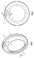
- the plurality of crenellations 60 may extend in generally axial alignment from the forward edge to the aft edge that is across the axial width, of the retained layer 50 of the inner airseal 40.
- the plurality of crenellations 60 are formed in the retained layer 50 at circumferentially spaced intervals about the entire inner circumference of inner airseal 40.
- Each crenellation 60 may be a recess, pocket or channel forming a concave depression in the retained layer 50. In the embodiment illustrated in FIG.
- the crenellations 60 comprise a plurality of generally flat-bottom channels machined into the retained layer of original material. It is to be understood that the crenellations 60 may also be formed as semi-circular grooves, as generally V-shaped grooves, as generally U-shaped grooves or as an elongated depression of other desired cross-section.
- a replacement layer 70 of new material is applied over the retained layer 50 and bonded to the exposed surface 52 of the retained layer 50.
- the replacement layer 70 of new material may be molded to shape in place.
- the replacement material may be injected into a mold (not shown) mated to the retained layer 50 and allowed to set up to form the outer replacement layer 70 of new material bonded to the retained layer 50.
- the mold may be configured to provide a face surface 72 on the replacement layer 70 that replicates the sealing surface 45 on the tip portion 44 of the original equipment manufacture seal element 42.
- the new material may be applied over the retained layer 50 by trowel, allowed to set up, and then machined to provide a desired face surface.
- the replacement layer 70 of new material may be self-adhering to the retained layer 50 of original material or a layer of adhesive may be applied to the exposed surface 52 of the retained layer 50.
- FIGS. 8, 9 and 10 there is depicted an exemplary embodiment of a repaired inner airseal 240, which constitutes the original equipment manufacture inner air seal 40, shown in FIGs. 4 and 5 , repaired in accordance with the method for repair disclosed herein.
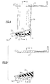
- the repaired inner airseal 240 is shown in a first cross-section taken through a portion of the repaired inner air seal 240 lying directly beneath one of the stator vanes 30.
- the replacement layer 70 of new material is bonded to the retained layer 50 of original material along a bond line 90 commensurate with the surface of the retained layer 50 exposed after machining away of the damaged or worn material from the seal element.
- FIG. 8 the repaired inner airseal 240 is shown in a first cross-section taken through a portion of the repaired inner air seal 240 lying directly beneath one of the stator vanes 30.
- the replacement layer 70 of new material is bonded to the retained layer 50 of original material along a bond line 90 commensurate with the surface of the retained layer 50 exposed after machining away of
- the repaired inner airseal 240 is shown in a second cross-section taken through a crenellation in a portion of the repaired inner air seal 240 lying intermediate a pair of stator vanes 30.
- the replacement layer 70 of new material is bonded to the retained layer 50 of original material along a bond line 92 commensurate with the surface of the retained layer 50 exposed after machining away original material in the retained layer 50 to form the crenellations 60.
- the sealing surface 72 on the replacement layer 70 of the repaired inner airseal 240 replicates the sealing surface 45 of the original equipment manufacture inner airseal 40.
- FIG. 10 a section of the circumferentially extending repaired inner airseal 240 is shown in a cross-section illustrating the placement of the crenellations 60 at circumferentially spaced intervals intermediate respective neighboring pairs of stator vanes 30.
- the crenellations 60 being cut into the retained layer 50, result in an increase in the total surface area of the substrate original material to which the replacement layer 50 of new material is bonded. Additionally, due to the presence of the crenellations 60, the bond surface does not follow a simple circumferential path at a uniform radius, but rather undulates between a two circumferential paths, one circumferential path following the surface of the retained layer 50 exposed upon removal of the layer of damaged or worn material from the original seal element 42 and the other circumferential path following along the bases 62 of the crenellations 60 formed in the retained layer 50.
- the resulting bond between the replacement layer 70 and the retained layer 50 is not only stronger due to the increased surface area associated with the bond, but also provides an anti-rotation resistance not present in bonds that follow a simple circumferential path as in conventional practice.
- the anti-rotation resistance arises from the undulating nature of the bond surface due to the presence of the crenellations 60 and provides resistance to circumferentially directed stresses arising from contact with the knife edge sealing elements carried on the rotor assembly as the knife edge sealing elements rotate along the stationary sealing surface 72 of the repaired inner airseal 240.
- the repaired inner airseal 240 can be distinguished from the original equipment manufacture inner airseal 40 by a witness line at the bond interface 90, 92, but will otherwise be indistinguishable in appearance and performance from the original equipment manufacture inner air seal 40.
- the inner airseal 240 may represent an original seal element manufactured by forming a layer 50 of a base material on a substrate surface, i.e. the inboard surface of the inboard shroud 22, forming a plurality of crenellations 60 in the face surface of the layer 50 of base material, and forming a layer of a seal material 70 on the crenellated layer 50 of base material.
- the layer 50 of base material may be bonded, either by self-adhesion or by a layer of adhesive, to the substrate surface.
- the layer 50 of base material is made thick enough to encapsulate the retaining clips 28.
- the method of forming the seal element may include the step of molding the layer 50 of base material in place on the substrate surface.
- the method of forming the seal element may include the step of molding the layer 70 of a seal material in place on the layer 50 of a base material having crenellations 60 formed therein.
- the seal material may be an elastomeric seal material
- the base material may be an elastomeric material or a non-elastomeric material suitable for supporting an elastomeric material.
Landscapes
- Engineering & Computer Science (AREA)
- Mechanical Engineering (AREA)
- General Engineering & Computer Science (AREA)
- Turbine Rotor Nozzle Sealing (AREA)
- Sealing Devices (AREA)
- Joining Of Glass To Other Materials (AREA)
- Structures Of Non-Positive Displacement Pumps (AREA)
Applications Claiming Priority (1)
| Application Number | Priority Date | Filing Date | Title |
|---|---|---|---|
| US12/750,156 US8910947B2 (en) | 2010-03-30 | 2010-03-30 | Method of forming a seal element |
Publications (3)
| Publication Number | Publication Date |
|---|---|
| EP2372101A2 true EP2372101A2 (fr) | 2011-10-05 |
| EP2372101A3 EP2372101A3 (fr) | 2014-11-05 |
| EP2372101B1 EP2372101B1 (fr) | 2021-04-28 |
Family
ID=43858218
Family Applications (1)
| Application Number | Title | Priority Date | Filing Date |
|---|---|---|---|
| EP11160309.8A Active EP2372101B1 (fr) | 2010-03-30 | 2011-03-29 | Procédé de fabrication d'un élément d'étanchéité |
Country Status (2)
| Country | Link |
|---|---|
| US (1) | US8910947B2 (fr) |
| EP (1) | EP2372101B1 (fr) |
Cited By (1)
| Publication number | Priority date | Publication date | Assignee | Title |
|---|---|---|---|---|
| FR3022578A1 (fr) * | 2014-06-23 | 2015-12-25 | Snecma | Procede de realisation et de reparation d’un distributeur de turbine d’une turbomachine |
Families Citing this family (7)
| Publication number | Priority date | Publication date | Assignee | Title |
|---|---|---|---|---|
| US9097124B2 (en) * | 2012-01-24 | 2015-08-04 | United Technologies Corporation | Gas turbine engine stator vane assembly with inner shroud |
| EP2735707B1 (fr) * | 2012-11-27 | 2017-04-05 | Safran Aero Boosters SA | Redresseur de turbomachine axiale avec virole interne segmentée et compresseur associé |
| DE102013212465B4 (de) | 2013-06-27 | 2015-03-12 | MTU Aero Engines AG | Dichtanordnung für eine Strömungsmaschine, eine Leitschaufelanordnung und eine Strömungsmaschine mit einer derartigen Dichtanordnung |
| US10213883B2 (en) * | 2016-02-22 | 2019-02-26 | General Electric Company | System and method for in situ repair of gas turbine engine casing clearance |
| US10724389B2 (en) | 2017-07-10 | 2020-07-28 | Raytheon Technologies Corporation | Stator vane assembly for a gas turbine engine |
| FR3081499B1 (fr) * | 2018-05-23 | 2021-05-28 | Safran Aircraft Engines | Secteur angulaire d'aubage de turbomachine a etancheite perfectionnee |
| US11834960B2 (en) | 2022-02-18 | 2023-12-05 | General Electric Company | Methods and apparatus to reduce deflection of an airfoil |
Family Cites Families (16)
| Publication number | Priority date | Publication date | Assignee | Title |
|---|---|---|---|---|
| GB851267A (en) * | 1958-04-28 | 1960-10-12 | Gen Motors Corp | Improvements relating to axial-flow compressors |
| US3053694A (en) * | 1961-02-20 | 1962-09-11 | Gen Electric | Abradable material |
| BE793005A (fr) * | 1971-12-20 | 1973-06-19 | Union Carbide Corp | Elements metalliques poreux renforces par une feuille |
| US3823950A (en) * | 1972-10-24 | 1974-07-16 | Laval Turbine | Improved pressure vented wear ring assembly for use in rotary machinery |
| US3843278A (en) * | 1973-06-04 | 1974-10-22 | United Aircraft Corp | Abradable seal construction |
| US4207024A (en) * | 1977-05-27 | 1980-06-10 | The United States Of America As Represented By The Administrator Of The National Aeronautics And Space Administration | Composite seal for turbomachinery |
| US4460185A (en) * | 1982-08-23 | 1984-07-17 | General Electric Company | Seal including a non-metallic abradable material |
| US4507841A (en) * | 1984-05-17 | 1985-04-02 | Vista Polymers Inc. | Removal and reinstallation of bottom entering agitator seals |
| US4764089A (en) * | 1986-08-07 | 1988-08-16 | Allied-Signal Inc. | Abradable strain-tolerant ceramic coated turbine shroud |
| US4924581A (en) * | 1988-11-22 | 1990-05-15 | Techniair, Inc. | Turbine air seal repair process |
| US5484665A (en) * | 1991-04-15 | 1996-01-16 | General Electric Company | Rotary seal member and method for making |
| US5655701A (en) | 1995-07-10 | 1997-08-12 | United Technologies Corporation | Method for repairing an abradable seal |
| US6352264B1 (en) * | 1999-12-17 | 2002-03-05 | United Technologies Corporation | Abradable seal having improved properties |
| EP1152124A1 (fr) * | 2000-05-04 | 2001-11-07 | Siemens Aktiengesellschaft | Garniture d'étanchéité |
| EP1426559B1 (fr) * | 2002-12-03 | 2009-02-18 | Techspace Aero S.A. | Virole interieure pour compresseur axial et utilisation |
| US7363707B2 (en) * | 2004-06-14 | 2008-04-29 | General Electric Company | Braze repair of shroud block seal teeth in a gas turbine engine |
-
2010
- 2010-03-30 US US12/750,156 patent/US8910947B2/en not_active Expired - Fee Related
-
2011
- 2011-03-29 EP EP11160309.8A patent/EP2372101B1/fr active Active
Non-Patent Citations (1)
| Title |
|---|
| None |
Cited By (6)
| Publication number | Priority date | Publication date | Assignee | Title |
|---|---|---|---|---|
| FR3022578A1 (fr) * | 2014-06-23 | 2015-12-25 | Snecma | Procede de realisation et de reparation d’un distributeur de turbine d’une turbomachine |
| WO2015197942A1 (fr) | 2014-06-23 | 2015-12-30 | Snecma | Procédé de réalisation et de réparation d'un organe de turbomachine et organe de turbomachine associé |
| CN106460536A (zh) * | 2014-06-23 | 2017-02-22 | 赛峰飞机发动机公司 | 用于创建和维修涡轮机组件的方法以及相关的涡轮机组件 |
| CN106460536B (zh) * | 2014-06-23 | 2019-01-04 | 赛峰飞机发动机公司 | 用于创建和维修涡轮机组件的方法以及相关的涡轮机组件 |
| US10443427B2 (en) | 2014-06-23 | 2019-10-15 | Safran Aircraft Engines | Method for creating and repairing a turbomachine component and associated turbomachine component |
| RU2713230C2 (ru) * | 2014-06-23 | 2020-02-04 | Сафран Эркрафт Энджинз | Способ изготовления и ремонта органа газотурбинного двигателя и соответствующий орган газотурбинного двигателя |
Also Published As
| Publication number | Publication date |
|---|---|
| EP2372101A3 (fr) | 2014-11-05 |
| EP2372101B1 (fr) | 2021-04-28 |
| US20110241295A1 (en) | 2011-10-06 |
| US8910947B2 (en) | 2014-12-16 |
Similar Documents
| Publication | Publication Date | Title |
|---|---|---|
| EP2372101B1 (fr) | Procédé de fabrication d'un élément d'étanchéité | |
| US9085053B2 (en) | In-situ turbine blade tip repair | |
| EP3042043B1 (fr) | Aube de turbomachine ayant un joint d'étanchéité à aile d'ange pour dissuadeurs de tailles différentes et procédé d'ajustement associé | |
| CN101148993B (zh) | 用于制作涡轮发动机的方法和设备 | |
| JP4870954B2 (ja) | ガスタービンエンジンロータ組立体を組立てるための方法及び装置 | |
| JP4020856B2 (ja) | タービンノズルセグメント及びその修理方法 | |
| JP2017075600A (ja) | シュラウド並びにタービン部品の製造方法 | |
| JP4474146B2 (ja) | 鋳造ノズルの組み立て式修理 | |
| US9009965B2 (en) | Method to center locate cutter teeth on shrouded turbine blades | |
| US20150096305A1 (en) | Method and system for providing cooling for turbine components | |
| US10895159B2 (en) | Removable anti-wear part for blade tip | |
| CN103732862B (zh) | 转子密封线凹槽修复 | |
| US20120099998A1 (en) | Support collar geometry for linear friction welding | |
| CA2779851C (fr) | Methode de reparation d'un segment de tuyere sur un moteur a turbine | |
| US20200157953A1 (en) | Composite fan blade with abrasive tip | |
| US20180128118A1 (en) | Turbine airfoil attachment with multi-radial serration profile | |
| EP4053376A1 (fr) | Systèmes et procédés de réparation de boîtier | |
| EP3124754A1 (fr) | Joint proche d'un trajet d'écoulement pour turbomachine | |
| US8708655B2 (en) | Blade for a gas turbine engine | |
| CN208106502U (zh) | 叶片及涡轮机 | |
| NL2002340C2 (en) | Method for repairing a cooled turbine nozzle segment. | |
| US11028719B2 (en) | Brush seal repair method | |
| US20170198584A1 (en) | Systems and methods for repairing a component of a rotary machine | |
| US11480061B2 (en) | Method for replacing metal airfoil with ceramic airfoil, and related turbomachine blade | |
| EP2960431B1 (fr) | Systèmes et procédés de réparation d'une surface de composants métalliques endommagés |
Legal Events
| Date | Code | Title | Description |
|---|---|---|---|
| PUAI | Public reference made under article 153(3) epc to a published international application that has entered the european phase |
Free format text: ORIGINAL CODE: 0009012 |
|
| AK | Designated contracting states |
Kind code of ref document: A2 Designated state(s): AL AT BE BG CH CY CZ DE DK EE ES FI FR GB GR HR HU IE IS IT LI LT LU LV MC MK MT NL NO PL PT RO RS SE SI SK SM TR |
|
| AX | Request for extension of the european patent |
Extension state: BA ME |
|
| PUAL | Search report despatched |
Free format text: ORIGINAL CODE: 0009013 |
|
| AK | Designated contracting states |
Kind code of ref document: A3 Designated state(s): AL AT BE BG CH CY CZ DE DK EE ES FI FR GB GR HR HU IE IS IT LI LT LU LV MC MK MT NL NO PL PT RO RS SE SI SK SM TR |
|
| AX | Request for extension of the european patent |
Extension state: BA ME |
|
| RIC1 | Information provided on ipc code assigned before grant |
Ipc: F04D 29/08 20060101ALI20141001BHEP Ipc: F01D 11/00 20060101AFI20141001BHEP Ipc: F01D 5/00 20060101ALI20141001BHEP |
|
| 17P | Request for examination filed |
Effective date: 20150505 |
|
| RBV | Designated contracting states (corrected) |
Designated state(s): AL AT BE BG CH CY CZ DE DK EE ES FI FR GB GR HR HU IE IS IT LI LT LU LV MC MK MT NL NO PL PT RO RS SE SI SK SM TR |
|
| RAP1 | Party data changed (applicant data changed or rights of an application transferred) |
Owner name: UNITED TECHNOLOGIES CORPORATION |
|
| STAA | Information on the status of an ep patent application or granted ep patent |
Free format text: STATUS: EXAMINATION IS IN PROGRESS |
|
| 17Q | First examination report despatched |
Effective date: 20190222 |
|
| GRAP | Despatch of communication of intention to grant a patent |
Free format text: ORIGINAL CODE: EPIDOSNIGR1 |
|
| STAA | Information on the status of an ep patent application or granted ep patent |
Free format text: STATUS: GRANT OF PATENT IS INTENDED |
|
| INTG | Intention to grant announced |
Effective date: 20201028 |
|
| GRAS | Grant fee paid |
Free format text: ORIGINAL CODE: EPIDOSNIGR3 |
|
| RAP1 | Party data changed (applicant data changed or rights of an application transferred) |
Owner name: RAYTHEON TECHNOLOGIES CORPORATION |
|
| GRAA | (expected) grant |
Free format text: ORIGINAL CODE: 0009210 |
|
| STAA | Information on the status of an ep patent application or granted ep patent |
Free format text: STATUS: THE PATENT HAS BEEN GRANTED |
|
| AK | Designated contracting states |
Kind code of ref document: B1 Designated state(s): AL AT BE BG CH CY CZ DE DK EE ES FI FR GB GR HR HU IE IS IT LI LT LU LV MC MK MT NL NO PL PT RO RS SE SI SK SM TR |
|
| REG | Reference to a national code |
Ref country code: GB Ref legal event code: FG4D |
|
| REG | Reference to a national code |
Ref country code: CH Ref legal event code: EP |
|
| REG | Reference to a national code |
Ref country code: DE Ref legal event code: R096 Ref document number: 602011070807 Country of ref document: DE |
|
| REG | Reference to a national code |
Ref country code: AT Ref legal event code: REF Ref document number: 1387265 Country of ref document: AT Kind code of ref document: T Effective date: 20210515 |
|
| REG | Reference to a national code |
Ref country code: IE Ref legal event code: FG4D |
|
| REG | Reference to a national code |
Ref country code: LT Ref legal event code: MG9D |
|
| REG | Reference to a national code |
Ref country code: AT Ref legal event code: MK05 Ref document number: 1387265 Country of ref document: AT Kind code of ref document: T Effective date: 20210428 |
|
| PG25 | Lapsed in a contracting state [announced via postgrant information from national office to epo] |
Ref country code: AT Free format text: LAPSE BECAUSE OF FAILURE TO SUBMIT A TRANSLATION OF THE DESCRIPTION OR TO PAY THE FEE WITHIN THE PRESCRIBED TIME-LIMIT Effective date: 20210428 Ref country code: BG Free format text: LAPSE BECAUSE OF FAILURE TO SUBMIT A TRANSLATION OF THE DESCRIPTION OR TO PAY THE FEE WITHIN THE PRESCRIBED TIME-LIMIT Effective date: 20210728 Ref country code: HR Free format text: LAPSE BECAUSE OF FAILURE TO SUBMIT A TRANSLATION OF THE DESCRIPTION OR TO PAY THE FEE WITHIN THE PRESCRIBED TIME-LIMIT Effective date: 20210428 Ref country code: FI Free format text: LAPSE BECAUSE OF FAILURE TO SUBMIT A TRANSLATION OF THE DESCRIPTION OR TO PAY THE FEE WITHIN THE PRESCRIBED TIME-LIMIT Effective date: 20210428 Ref country code: NL Free format text: LAPSE BECAUSE OF FAILURE TO SUBMIT A TRANSLATION OF THE DESCRIPTION OR TO PAY THE FEE WITHIN THE PRESCRIBED TIME-LIMIT Effective date: 20210428 Ref country code: LT Free format text: LAPSE BECAUSE OF FAILURE TO SUBMIT A TRANSLATION OF THE DESCRIPTION OR TO PAY THE FEE WITHIN THE PRESCRIBED TIME-LIMIT Effective date: 20210428 |
|
| PG25 | Lapsed in a contracting state [announced via postgrant information from national office to epo] |
Ref country code: PT Free format text: LAPSE BECAUSE OF FAILURE TO SUBMIT A TRANSLATION OF THE DESCRIPTION OR TO PAY THE FEE WITHIN THE PRESCRIBED TIME-LIMIT Effective date: 20210830 Ref country code: NO Free format text: LAPSE BECAUSE OF FAILURE TO SUBMIT A TRANSLATION OF THE DESCRIPTION OR TO PAY THE FEE WITHIN THE PRESCRIBED TIME-LIMIT Effective date: 20210728 Ref country code: PL Free format text: LAPSE BECAUSE OF FAILURE TO SUBMIT A TRANSLATION OF THE DESCRIPTION OR TO PAY THE FEE WITHIN THE PRESCRIBED TIME-LIMIT Effective date: 20210428 Ref country code: ES Free format text: LAPSE BECAUSE OF FAILURE TO SUBMIT A TRANSLATION OF THE DESCRIPTION OR TO PAY THE FEE WITHIN THE PRESCRIBED TIME-LIMIT Effective date: 20210428 Ref country code: LV Free format text: LAPSE BECAUSE OF FAILURE TO SUBMIT A TRANSLATION OF THE DESCRIPTION OR TO PAY THE FEE WITHIN THE PRESCRIBED TIME-LIMIT Effective date: 20210428 Ref country code: IS Free format text: LAPSE BECAUSE OF FAILURE TO SUBMIT A TRANSLATION OF THE DESCRIPTION OR TO PAY THE FEE WITHIN THE PRESCRIBED TIME-LIMIT Effective date: 20210828 Ref country code: GR Free format text: LAPSE BECAUSE OF FAILURE TO SUBMIT A TRANSLATION OF THE DESCRIPTION OR TO PAY THE FEE WITHIN THE PRESCRIBED TIME-LIMIT Effective date: 20210729 Ref country code: RS Free format text: LAPSE BECAUSE OF FAILURE TO SUBMIT A TRANSLATION OF THE DESCRIPTION OR TO PAY THE FEE WITHIN THE PRESCRIBED TIME-LIMIT Effective date: 20210428 Ref country code: SE Free format text: LAPSE BECAUSE OF FAILURE TO SUBMIT A TRANSLATION OF THE DESCRIPTION OR TO PAY THE FEE WITHIN THE PRESCRIBED TIME-LIMIT Effective date: 20210428 |
|
| REG | Reference to a national code |
Ref country code: NL Ref legal event code: MP Effective date: 20210428 |
|
| PG25 | Lapsed in a contracting state [announced via postgrant information from national office to epo] |
Ref country code: SM Free format text: LAPSE BECAUSE OF FAILURE TO SUBMIT A TRANSLATION OF THE DESCRIPTION OR TO PAY THE FEE WITHIN THE PRESCRIBED TIME-LIMIT Effective date: 20210428 Ref country code: SK Free format text: LAPSE BECAUSE OF FAILURE TO SUBMIT A TRANSLATION OF THE DESCRIPTION OR TO PAY THE FEE WITHIN THE PRESCRIBED TIME-LIMIT Effective date: 20210428 Ref country code: EE Free format text: LAPSE BECAUSE OF FAILURE TO SUBMIT A TRANSLATION OF THE DESCRIPTION OR TO PAY THE FEE WITHIN THE PRESCRIBED TIME-LIMIT Effective date: 20210428 Ref country code: DK Free format text: LAPSE BECAUSE OF FAILURE TO SUBMIT A TRANSLATION OF THE DESCRIPTION OR TO PAY THE FEE WITHIN THE PRESCRIBED TIME-LIMIT Effective date: 20210428 Ref country code: CZ Free format text: LAPSE BECAUSE OF FAILURE TO SUBMIT A TRANSLATION OF THE DESCRIPTION OR TO PAY THE FEE WITHIN THE PRESCRIBED TIME-LIMIT Effective date: 20210428 Ref country code: RO Free format text: LAPSE BECAUSE OF FAILURE TO SUBMIT A TRANSLATION OF THE DESCRIPTION OR TO PAY THE FEE WITHIN THE PRESCRIBED TIME-LIMIT Effective date: 20210428 |
|
| REG | Reference to a national code |
Ref country code: DE Ref legal event code: R097 Ref document number: 602011070807 Country of ref document: DE |
|
| PLBE | No opposition filed within time limit |
Free format text: ORIGINAL CODE: 0009261 |
|
| STAA | Information on the status of an ep patent application or granted ep patent |
Free format text: STATUS: NO OPPOSITION FILED WITHIN TIME LIMIT |
|
| 26N | No opposition filed |
Effective date: 20220131 |
|
| PG25 | Lapsed in a contracting state [announced via postgrant information from national office to epo] |
Ref country code: IS Free format text: LAPSE BECAUSE OF FAILURE TO SUBMIT A TRANSLATION OF THE DESCRIPTION OR TO PAY THE FEE WITHIN THE PRESCRIBED TIME-LIMIT Effective date: 20210828 Ref country code: AL Free format text: LAPSE BECAUSE OF FAILURE TO SUBMIT A TRANSLATION OF THE DESCRIPTION OR TO PAY THE FEE WITHIN THE PRESCRIBED TIME-LIMIT Effective date: 20210428 |
|
| PG25 | Lapsed in a contracting state [announced via postgrant information from national office to epo] |
Ref country code: IT Free format text: LAPSE BECAUSE OF FAILURE TO SUBMIT A TRANSLATION OF THE DESCRIPTION OR TO PAY THE FEE WITHIN THE PRESCRIBED TIME-LIMIT Effective date: 20210428 |
|
| PG25 | Lapsed in a contracting state [announced via postgrant information from national office to epo] |
Ref country code: MC Free format text: LAPSE BECAUSE OF FAILURE TO SUBMIT A TRANSLATION OF THE DESCRIPTION OR TO PAY THE FEE WITHIN THE PRESCRIBED TIME-LIMIT Effective date: 20210428 |
|
| REG | Reference to a national code |
Ref country code: CH Ref legal event code: PL |
|
| REG | Reference to a national code |
Ref country code: BE Ref legal event code: MM Effective date: 20220331 |
|
| PG25 | Lapsed in a contracting state [announced via postgrant information from national office to epo] |
Ref country code: LU Free format text: LAPSE BECAUSE OF NON-PAYMENT OF DUE FEES Effective date: 20220329 Ref country code: LI Free format text: LAPSE BECAUSE OF NON-PAYMENT OF DUE FEES Effective date: 20220331 Ref country code: IE Free format text: LAPSE BECAUSE OF NON-PAYMENT OF DUE FEES Effective date: 20220329 Ref country code: CH Free format text: LAPSE BECAUSE OF NON-PAYMENT OF DUE FEES Effective date: 20220331 |
|
| PG25 | Lapsed in a contracting state [announced via postgrant information from national office to epo] |
Ref country code: BE Free format text: LAPSE BECAUSE OF NON-PAYMENT OF DUE FEES Effective date: 20220331 |
|
| P01 | Opt-out of the competence of the unified patent court (upc) registered |
Effective date: 20230519 |
|
| PG25 | Lapsed in a contracting state [announced via postgrant information from national office to epo] |
Ref country code: HU Free format text: LAPSE BECAUSE OF FAILURE TO SUBMIT A TRANSLATION OF THE DESCRIPTION OR TO PAY THE FEE WITHIN THE PRESCRIBED TIME-LIMIT; INVALID AB INITIO Effective date: 20110329 |
|
| PG25 | Lapsed in a contracting state [announced via postgrant information from national office to epo] |
Ref country code: MK Free format text: LAPSE BECAUSE OF FAILURE TO SUBMIT A TRANSLATION OF THE DESCRIPTION OR TO PAY THE FEE WITHIN THE PRESCRIBED TIME-LIMIT Effective date: 20210428 Ref country code: CY Free format text: LAPSE BECAUSE OF FAILURE TO SUBMIT A TRANSLATION OF THE DESCRIPTION OR TO PAY THE FEE WITHIN THE PRESCRIBED TIME-LIMIT Effective date: 20210428 |
|
| PGFP | Annual fee paid to national office [announced via postgrant information from national office to epo] |
Ref country code: DE Payment date: 20240220 Year of fee payment: 14 Ref country code: GB Payment date: 20240220 Year of fee payment: 14 |
|
| PGFP | Annual fee paid to national office [announced via postgrant information from national office to epo] |
Ref country code: FR Payment date: 20240220 Year of fee payment: 14 |
|
| PG25 | Lapsed in a contracting state [announced via postgrant information from national office to epo] |
Ref country code: MT Free format text: LAPSE BECAUSE OF FAILURE TO SUBMIT A TRANSLATION OF THE DESCRIPTION OR TO PAY THE FEE WITHIN THE PRESCRIBED TIME-LIMIT Effective date: 20210428 |
|
| REG | Reference to a national code |
Ref country code: DE Ref legal event code: R119 Ref document number: 602011070807 Country of ref document: DE |
|
| GBPC | Gb: european patent ceased through non-payment of renewal fee |
Effective date: 20250329 |
|
| PG25 | Lapsed in a contracting state [announced via postgrant information from national office to epo] |
Ref country code: TR Free format text: LAPSE BECAUSE OF FAILURE TO SUBMIT A TRANSLATION OF THE DESCRIPTION OR TO PAY THE FEE WITHIN THE PRESCRIBED TIME-LIMIT Effective date: 20210428 |
|
| PG25 | Lapsed in a contracting state [announced via postgrant information from national office to epo] |
Ref country code: DE Free format text: LAPSE BECAUSE OF NON-PAYMENT OF DUE FEES Effective date: 20251001 |
|
| PG25 | Lapsed in a contracting state [announced via postgrant information from national office to epo] |
Ref country code: GB Free format text: LAPSE BECAUSE OF NON-PAYMENT OF DUE FEES Effective date: 20250329 |
|
| PG25 | Lapsed in a contracting state [announced via postgrant information from national office to epo] |
Ref country code: FR Free format text: LAPSE BECAUSE OF NON-PAYMENT OF DUE FEES Effective date: 20250331 |