EP2372909A2 - Resonatorelement, Resonator, Oszillator und elektronische Vorrichtung - Google Patents
Resonatorelement, Resonator, Oszillator und elektronische Vorrichtung Download PDFInfo
- Publication number
- EP2372909A2 EP2372909A2 EP11158240A EP11158240A EP2372909A2 EP 2372909 A2 EP2372909 A2 EP 2372909A2 EP 11158240 A EP11158240 A EP 11158240A EP 11158240 A EP11158240 A EP 11158240A EP 2372909 A2 EP2372909 A2 EP 2372909A2
- Authority
- EP
- European Patent Office
- Prior art keywords
- resonator element
- vibrating arm
- base portion
- vibrating
- resonator
- Prior art date
- Legal status (The legal status is an assumption and is not a legal conclusion. Google has not performed a legal analysis and makes no representation as to the accuracy of the status listed.)
- Withdrawn
Links
- 239000013078 crystal Substances 0.000 claims description 22
- 239000010453 quartz Substances 0.000 claims description 17
- VYPSYNLAJGMNEJ-UHFFFAOYSA-N silicon dioxide Inorganic materials O=[Si]=O VYPSYNLAJGMNEJ-UHFFFAOYSA-N 0.000 claims description 17
- 230000007423 decrease Effects 0.000 description 34
- 230000000694 effects Effects 0.000 description 26
- 239000000758 substrate Substances 0.000 description 15
- 230000003247 decreasing effect Effects 0.000 description 12
- 239000000463 material Substances 0.000 description 10
- 230000002349 favourable effect Effects 0.000 description 9
- PXHVJJICTQNCMI-UHFFFAOYSA-N Nickel Chemical compound [Ni] PXHVJJICTQNCMI-UHFFFAOYSA-N 0.000 description 5
- 229910045601 alloy Inorganic materials 0.000 description 3
- 239000000956 alloy Substances 0.000 description 3
- 239000000919 ceramic Substances 0.000 description 3
- 239000011651 chromium Substances 0.000 description 3
- 230000005284 excitation Effects 0.000 description 3
- 239000011521 glass Substances 0.000 description 3
- 239000010931 gold Substances 0.000 description 3
- 229910000833 kovar Inorganic materials 0.000 description 3
- 229910052751 metal Inorganic materials 0.000 description 3
- 239000002184 metal Substances 0.000 description 3
- 238000004088 simulation Methods 0.000 description 3
- VYZAMTAEIAYCRO-UHFFFAOYSA-N Chromium Chemical compound [Cr] VYZAMTAEIAYCRO-UHFFFAOYSA-N 0.000 description 2
- BQCADISMDOOEFD-UHFFFAOYSA-N Silver Chemical compound [Ag] BQCADISMDOOEFD-UHFFFAOYSA-N 0.000 description 2
- 229910052804 chromium Inorganic materials 0.000 description 2
- 238000004891 communication Methods 0.000 description 2
- 239000000470 constituent Substances 0.000 description 2
- 238000010586 diagram Methods 0.000 description 2
- PCHJSUWPFVWCPO-UHFFFAOYSA-N gold Chemical compound [Au] PCHJSUWPFVWCPO-UHFFFAOYSA-N 0.000 description 2
- 229910052737 gold Inorganic materials 0.000 description 2
- 239000011261 inert gas Substances 0.000 description 2
- 229910052759 nickel Inorganic materials 0.000 description 2
- 230000010355 oscillation Effects 0.000 description 2
- 238000004080 punching Methods 0.000 description 2
- 238000007789 sealing Methods 0.000 description 2
- 229910052709 silver Inorganic materials 0.000 description 2
- 239000004332 silver Substances 0.000 description 2
- 238000003466 welding Methods 0.000 description 2
- WSMQKESQZFQMFW-UHFFFAOYSA-N 5-methyl-pyrazole-3-carboxylic acid Chemical compound CC1=CC(C(O)=O)=NN1 WSMQKESQZFQMFW-UHFFFAOYSA-N 0.000 description 1
- 241000251468 Actinopterygii Species 0.000 description 1
- 229910000531 Co alloy Inorganic materials 0.000 description 1
- WQZGKKKJIJFFOK-GASJEMHNSA-N Glucose Natural products OC[C@H]1OC(O)[C@H](O)[C@@H](O)[C@@H]1O WQZGKKKJIJFFOK-GASJEMHNSA-N 0.000 description 1
- 229910001030 Iron–nickel alloy Inorganic materials 0.000 description 1
- 241001076195 Lampsilis ovata Species 0.000 description 1
- KGWWEXORQXHJJQ-UHFFFAOYSA-N [Fe].[Co].[Ni] Chemical compound [Fe].[Co].[Ni] KGWWEXORQXHJJQ-UHFFFAOYSA-N 0.000 description 1
- 230000005856 abnormality Effects 0.000 description 1
- 230000002411 adverse Effects 0.000 description 1
- 238000005452 bending Methods 0.000 description 1
- 238000000151 deposition Methods 0.000 description 1
- 230000008021 deposition Effects 0.000 description 1
- 238000003745 diagnosis Methods 0.000 description 1
- 238000005530 etching Methods 0.000 description 1
- 239000008103 glucose Substances 0.000 description 1
- 239000004973 liquid crystal related substance Substances 0.000 description 1
- GQYHUHYESMUTHG-UHFFFAOYSA-N lithium niobate Chemical compound [Li+].[O-][Nb](=O)=O GQYHUHYESMUTHG-UHFFFAOYSA-N 0.000 description 1
- 238000005259 measurement Methods 0.000 description 1
- 238000000034 method Methods 0.000 description 1
- 238000010295 mobile communication Methods 0.000 description 1
- 238000000059 patterning Methods 0.000 description 1
- 238000000206 photolithography Methods 0.000 description 1
- 238000005498 polishing Methods 0.000 description 1
- 238000012545 processing Methods 0.000 description 1
- 239000004065 semiconductor Substances 0.000 description 1
- 238000004904 shortening Methods 0.000 description 1
- 229910052710 silicon Inorganic materials 0.000 description 1
- 239000010703 silicon Substances 0.000 description 1
- 238000004544 sputter deposition Methods 0.000 description 1
- 230000000087 stabilizing effect Effects 0.000 description 1
- 238000012546 transfer Methods 0.000 description 1
Images


Classifications
-
- H—ELECTRICITY
- H03—ELECTRONIC CIRCUITRY
- H03H—IMPEDANCE NETWORKS, e.g. RESONANT CIRCUITS; RESONATORS
- H03H9/00—Networks comprising electromechanical or electro-acoustic elements; Electromechanical resonators
- H03H9/15—Constructional features of resonators consisting of piezoelectric or electrostrictive material
- H03H9/21—Crystal tuning forks
-
- H—ELECTRICITY
- H03—ELECTRONIC CIRCUITRY
- H03H—IMPEDANCE NETWORKS, e.g. RESONANT CIRCUITS; RESONATORS
- H03H9/00—Networks comprising electromechanical or electro-acoustic elements; Electromechanical resonators
- H03H9/02—Details
- H03H9/05—Holders or supports
- H03H9/0538—Constructional combinations of supports or holders with electromechanical or other electronic elements
- H03H9/0547—Constructional combinations of supports or holders with electromechanical or other electronic elements consisting of a vertical arrangement
-
- H—ELECTRICITY
- H03—ELECTRONIC CIRCUITRY
- H03H—IMPEDANCE NETWORKS, e.g. RESONANT CIRCUITS; RESONATORS
- H03H9/00—Networks comprising electromechanical or electro-acoustic elements; Electromechanical resonators
- H03H9/02—Details
- H03H9/05—Holders or supports
- H03H9/10—Mounting in enclosures
- H03H9/1007—Mounting in enclosures for bulk acoustic wave [BAW] devices
- H03H9/1014—Mounting in enclosures for bulk acoustic wave [BAW] devices the enclosure being defined by a frame built on a substrate and a cap, the frame having no mechanical contact with the BAW device
-
- H—ELECTRICITY
- H03—ELECTRONIC CIRCUITRY
- H03H—IMPEDANCE NETWORKS, e.g. RESONANT CIRCUITS; RESONATORS
- H03H9/00—Networks comprising electromechanical or electro-acoustic elements; Electromechanical resonators
- H03H9/15—Constructional features of resonators consisting of piezoelectric or electrostrictive material
- H03H9/21—Crystal tuning forks
- H03H9/215—Crystal tuning forks consisting of quartz
-
- H—ELECTRICITY
- H03—ELECTRONIC CIRCUITRY
- H03H—IMPEDANCE NETWORKS, e.g. RESONANT CIRCUITS; RESONATORS
- H03H9/00—Networks comprising electromechanical or electro-acoustic elements; Electromechanical resonators
- H03H9/24—Constructional features of resonators of material which is not piezoelectric, electrostrictive, or magnetostrictive
- H03H9/2405—Constructional features of resonators of material which is not piezoelectric, electrostrictive, or magnetostrictive of microelectro-mechanical resonators
- H03H9/2447—Beam resonators
- H03H9/2457—Clamped-free beam resonators
-
- H—ELECTRICITY
- H03—ELECTRONIC CIRCUITRY
- H03H—IMPEDANCE NETWORKS, e.g. RESONANT CIRCUITS; RESONATORS
- H03H9/00—Networks comprising electromechanical or electro-acoustic elements; Electromechanical resonators
- H03H9/24—Constructional features of resonators of material which is not piezoelectric, electrostrictive, or magnetostrictive
- H03H9/2405—Constructional features of resonators of material which is not piezoelectric, electrostrictive, or magnetostrictive of microelectro-mechanical resonators
- H03H9/2468—Tuning fork resonators
- H03H9/2478—Single-Ended Tuning Fork resonators
-
- H—ELECTRICITY
- H03—ELECTRONIC CIRCUITRY
- H03H—IMPEDANCE NETWORKS, e.g. RESONANT CIRCUITS; RESONATORS
- H03H3/00—Apparatus or processes specially adapted for the manufacture of impedance networks, resonating circuits, resonators
- H03H3/007—Apparatus or processes specially adapted for the manufacture of impedance networks, resonating circuits, resonators for the manufacture of electromechanical resonators or networks
- H03H3/02—Apparatus or processes specially adapted for the manufacture of impedance networks, resonating circuits, resonators for the manufacture of electromechanical resonators or networks for the manufacture of piezoelectric or electrostrictive resonators or networks
- H03H3/04—Apparatus or processes specially adapted for the manufacture of impedance networks, resonating circuits, resonators for the manufacture of electromechanical resonators or networks for the manufacture of piezoelectric or electrostrictive resonators or networks for obtaining desired frequency or temperature coefficient
- H03H2003/0414—Resonance frequency
- H03H2003/0492—Resonance frequency during the manufacture of a tuning-fork
Definitions
- the present invention relates to a resonator element such as a flexural resonator element that vibrates, for example, in a flexural vibration mode, a resonator or an oscillator that uses the resonator element, and an electronic device having the oscillator.
- a resonator element such as a flexural resonator element that vibrates, for example, in a flexural vibration mode, a resonator or an oscillator that uses the resonator element, and an electronic device having the oscillator.
- a tuning-fork type flexural resonator element in which a pair of vibrating arms is extended from a base portion made from a piezoelectric material such as a quartz crystal so as to vibrate in the direction towards or away from each other in the horizontal direction is widely used as a resonator element that vibrates in the flexural vibration mode.
- the vibrating arms of the tuning-fork type flexural resonator element are excited, if there is a loss of the vibration energy thereof, it decreases the performance of the resonator element by, for example, an increase of the CI (Crystal Impedance) value or a decrease of the Q value.
- CI Crystal Impedance
- a tuning-fork type quartz crystal resonator element in which a cutout portion or a notch (notched groove) with a predetermined depth is formed on both sides of the base portion from which the vibrating arms extend is known (for example, see JP-A-2002-261575 and JP-A-2004-260718 ).
- this tuning-fork type quartz crystal resonator element when the vibration of the vibrating arms includes a vertical component, the loss of vibration from the base portion is suppressed by the notch. Thus, a confinement effect of the vibration energy increases, and the Q value is controlled and the fluctuation of the Q value between the resonator elements is prevented.
- the decrease of the Q value occurs not only due to the mechanical loss of vibration energy described above, but also occurs due to thermal conduction caused by a temperature difference between a contracted portion where compressive stress of the vibrating arms performing flexural vibration acts and an expanded portion where tensile stress acts.
- the decrease of the Q value caused by thermal conduction is referred to as a thermoelastic loss effect.
- a tuning-fork type resonator element in which a groove or a hole is formed on the central line of a vibrating arm (vibrating beam) having a rectangular section in order to prevent or suppress the decrease of the Q value due to the thermoelastic loss effect is disclosed in JP-UM-A-2-32229, for example.
- miniaturized information devices such as HDDs (Hard Disk Drives), mobile computers, or IC cards, mobile communication devices such as portable phones, car phones, or paging systems, and vibration gyro sensors.
- HDDs Hard Disk Drives
- mobile computers or IC cards
- mobile communication devices such as portable phones, car phones, or paging systems
- vibration gyro sensors In line with this, there is a higher level of demand for miniaturization of resonator elements mounted in these electronic devices.
- a resonator element capable of suppressing the occurrence of such a high-order vibration mode, decreasing the frequency, and stabilizing the vibration characteristics
- a resonator element in which a weight portion having a larger width than a general portion (arm portion) of a vibrating arm is formed at the tip end of the vibrating arm is disclosed in JP-UM-A-2005-5896, for example.
- the present inventor has found that when the resonator element has a structure in which it has a vibrating arm which includes both an elongated groove and a weight portion, if the occupancy of the length of the weight portion with respect to the entire length in the longitudinal direction of the vibrating arm is too small or too large, it is not possible to obtain a desirable effect of decreasing the frequency with the weight portion and a desirable effect of suppressing thermoelastic loss with the elongated groove.
- the present inventor has also found that when the occupancy of the length of the weight portion with respect to the entire length in the longitudinal direction of the vibrating arm is within a certain range, it is possible to obtain the desired Q value by effect of decreasing the frequency with the weight portion and the desirable effect of suppressing thermoelastic loss with the elongated groove.
- An advantage of some aspects of the invention is to solve at least a part of the problems described above and the invention can be implemented as the following forms or application examples.
- This application example of the invention is directed to a resonator element including a base portion; and a vibrating arm which is extended from the base portion, in which the vibrating arm is provided with a bottomed elongated groove which has an opening along at least one principal surface of both principal surfaces of the vibrating arm, the vibrating arm is provided with a weight portion which is formed at a tip end side of the vibrating arm on the opposite side of a root of the vibrating arm attached to the base portion and which has a larger width than the width of the vibrating arm on the root side attached to the base portion, and the proportion of the length of the weight portion to the length from the root attached to the base portion to a tip end of the vibrating arm in a longitudinal direction of the vibrating arm is within a range of 35% to 41%.
- the present inventor has found that in the resonator element, the elongated groove provided in the vibrating arm improves the vibration efficiency and decreases the CI value, and the weight portion at the tip end of the vibrating arm performs the function of a weight.
- the thermoelastic loss decreases and the effect of sufficiently suppressing the decrease of the Q value is obtained. Therefore, it is possible to provide a resonator element in which miniaturization is realized and a decrease of the Q value is suppressed, and which has a low frequency and favorable vibration characteristics.
- This application example of the invention is directed to the resonator element, wherein the proportion of the length of the weight portion is within a range of 36% to 40%.
- This application example of the invention is directed to the resonator element, wherein the proportion of the length of the weight portion is within a range of 37% to 39%.
- This application example of the invention is directed to the resonator element, wherein the resonator element further includes two vibrating arms which are extended from the base portion; and a supporting arm which is formed so as to extend from a portion of the base portion between the two vibrating arms in the longitudinal direction of the vibrating arm.
- the supporting arm is provided between a pair of vibrating arms, it is possible to suppress changes in operation parameters of the resonator element which may occur due to the disturbance of the air between the respective vibrating arms when the respective vibrating arms vibrate, particularly when the respective vibrating arms vibrate in the direction toward each other.
- This application example of the invention is directed to the resonator element, wherein the base portion and the vibrating arm are formed from a quartz crystal.
- This application example of the invention is directed to the resonator element, wherein the resonator element is a flexural resonator element which has a flexural vibration mode.
- the present inventor has found that in a flexural resonator element which has a flexural vibration mode, it is possible to obtain a more noticeable effect of decreasing the frequency and suppressing the decrease of the Q value.
- This application example of the invention is directed to a resonator including the resonator element and a package that accommodates the resonator element.
- the resonator since the resonator includes the resonator element of the above aspect, it is possible to provide a small-sized resonator in which the vibration efficiency is improved by the elongated groove to decrease the CI value, and the frequency is decreased by the weight portion, and the decrease of the Q value resulting from a thermoelastic loss is suppressed, and which has favorable vibration characteristics.
- This application example of the invention is directed to an oscillator including the resonator element according to the above aspect; a circuit portion that is electrically connected to the resonator element; and a package that accommodates the resonator element and the circuit portion.
- the oscillator since the oscillator includes the resonator element of the above aspect, it is possible to provide an oscillator in which the vibration efficiency is improved by the elongated groove to decrease the CI value, and the frequency is decreased by the weight portion and the decrease of the Q value resulting from thermoelastic loss is suppressed, and which has favorable vibration characteristics.
- This application example of the invention is directed to an electronic device including the oscillator according to the above aspect.
- the electronic device since the electronic device includes the oscillator of the above aspect, the electronic device can achieve a further miniaturization and improvement in reliability.
- Fig. 1A is a top view on one principal surface side, schematically illustrating an embodiment of a resonator element provided in an electronic device according to the invention
- Fig. 1B is a cross-sectional enlarged view of a cross section taken along the line IB-IB in Fig. 1A .
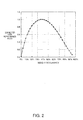
- Fig. 2 is a graph showing the relationship between the occupancy of a weight portion of the resonator element and a high performance index.
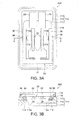
- Fig. 3A is a schematic top view illustrating an embodiment of a resonator having the resonator element as seen from above, and Fig. 3B is a cross-sectional view taken along the line IIIB-IIIB in Fig. 3A .
- Fig. 4A is a schematic top view illustrating an embodiment of an oscillator having the resonator element as seen from above
- Fig. 4B is a cross-sectional view taken along the line IVB-IVB in Fig. 4A .
- Fig. 5 is a perspective view showing a simplified configuration of a portable phone as an example of an electronic device.
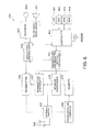
- Fig. 6 is a circuit block diagram of the portable phone.
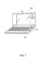
- Fig. 7 is a perspective view showing a simplified configuration of a personal computer as an example of an electronic device.
- FIGs. 1A and 1B schematically illustrate a resonator element according to this embodiment, in which Fig. 1A is a top view on one principal surface, and Fig. 1B is a cross-sectional enlarged view of a cross section taken along the line IB-IB in Fig. 1A .
- a resonator element 20 of this embodiment is a resonator element which has a flexural vibration mode and which is formed from a piezoelectric material such as a quartz crystal, lithium tantalate, or lithium niobate.
- a quartz crystal wafer obtained by dicing and polishing a quartz crystal Z plate to a predetermined thickness is used.
- the quartz crystal Z plate is cut while being rotated within the angle range of 0° to 5° in the clockwise direction about the Z axis of an orthogonal coordinate system made up of X, Y, and Z axes.
- the resonator element 20 of this embodiment is a quartz crystal resonator element which is formed so as to have a so-called tuning-fork type outer shape and which includes a base portion 21 formed by processing the quartz crystal Z plate and a pair of vibrating arms 22 extending in parallel by being divided into two stages from one end side (the upper end side in the drawing) of the base portion 21.
- a pair of notches 31 is formed so as to extend in opposite directions along one straight line so that it has a shape that is bound to both principal surfaces of the base portion 21.
- the base portion 21 includes first and second portions 21a and 21b which are positioned on both sides of the base portion 21 with the pair of notches 31 disposed therebetween and a connecting portion 21c which connects the first and second portions 21a and 21b between the pair of notches 31.
- the notches 31 block the transfer of vibration of the respective vibrating arms 22, it is possible to suppress a so-called vibration leakage which is a phenomenon where a vibration is transferred to the outside through the base portion 21 and a supporting arm 30, and to prevent an increase of the CI value.
- the shape of the respective notches 31 is adjusted to an optimum width and length so as to ensure the strength of the resonator element 20 against dropping and minimize the vibration leakage.
- each vibrating arm 22 extends from the first portion 21a of the base portion 21 in a direction parallel to both principal surfaces (the front and rear surfaces of the drawing sheet). Moreover, each vibrating arm 22 has the two principal surfaces and two side surfaces that connect the two principal surfaces on both sides.
- Each vibrating arm 22 has a general portion 23 which is disposed at the central portion thereof and which is a major vibrating portion of the vibrating arm 22. Moreover, each vibrating arm 22 has a large width portion 24 which is disposed in a root portion connected to the base portion 21 and of which the width between the two side surfaces gradually increases from the general portion 23 towards the base portion 21 and reaches the maximum at a root portion attached to the base portion 21. As described above, since each vibrating arm 22 has the large width portion 24, the vibrating arm 22 is connected to the base portion 21 with the large width. Thus, the rigidity increases and the impact resistance or the like improves.
- a weight portion 29 having a larger width than the general portion 23 is formed at a tip end side of each vibrating arm 22 on the opposite side of the root attached to the base portion 21. Since the weight portion 29 is formed at the tip end of each vibrating arm 22, the tip end performs the function of a weight. Thus, it is possible to decrease the frequency without increasing the length of the vibrating arm 22.
- each vibrating arm 22 of the resonator element 20 In the longitudinal direction (in this example, the extension direction of each vibrating arm 22 from the first portion 21a of the base portion 21) of each vibrating arm 22 of the resonator element 20, the proportion of the length 1 of the weight portion 29 to the length L from the root attached to the base portion 21 to the tip end is adjusted so as to be within the range of 35% to 41%.
- the present inventor has found that when the resonator element 20 is configured in such a way, since the weight portion 29 which is the tip end of each vibrating arm 22 performs the function of a weight, it is possible to obtain an effect of suppressing the frequency to a sufficiently low value without increasing the length of the vibrating arm 22. Moreover, it is possible to obtain an effect of decreasing thermoelastic loss and sufficiently suppressing the decrease of the Q value (details of which will be described later).
- one bottomed elongated groove 26a is provided along the longitudinal direction thereof.
- one elongated groove 26b is provided along the longitudinal direction of the vibrating arm 22.
- one bottomed groove 26b is provided on the other principal surface of the other vibrating arm 22 (the right one on the drawing sheet). That is, the elongated grooves 26a and 26b have an opening which is positioned along the principal surface.
- the rigidity decreases and the vibrating arm 22 can easily vibrate.
- the vibrating arm 22 is able to vibrate efficiently and exhibit favorable vibration characteristics.
- the elongated grooves 26a and 26b narrow the flow path of heat resulting from changes in the temperature occurring in projecting portions 25 on both side surfaces of the vibrating arm 22 due to deformation associated with vibrations near the root portion of each vibrating arm 22 attached to the base portion 21.
- an adverse effect resulting from the thermoelastic loss such as, for example, an increase of the CI value or a decrease of the Q value.
- the resonator element 20 of this embodiment has a pair of supporting arms 30 extending from the second portion 21b of the base portion 21.
- the pair of supporting arms 30 extends in a mutually opposite direction which is the direction crossing the extension direction of the pair of vibrating arms 22 from the base portion 21, and is bent at approximately a right angle in a bent portion 32 and then extends in parallel to the extension direction of the pair of vibrating arms 22.
- the supporting arm 30 includes a fixing region which is disposed closer to the tip end side (the side of the vibrating arm 22 close to the weight portion 29) than the bent portion 32 and which is attached to a package or the like described later. Since the resonator element 20 is attached so as to be supported by the fixing region of the supporting arm 30, the vibrating arm 22 and the base portion 21 can be floated from the fixed surface of the resonator element 20.
- each vibrating arm 22 including the respective elongated grooves 26a and 26b and the two side surfaces thereof, excitation electrodes 33 and 34 are formed (see Fig. 1B ).
- the two side surfaces of the vibrating arm 22 are expanded and contracted, whereby the vibrating arm 22 vibrates.
- the excitation electrodes 33 and 34 can be formed by etching a quartz crystal to form an outer shape including the elongated grooves 26a and 26b of the resonator element 20, forming an electrode layer, for example, made from gold (Au) by deposition or sputtering on a base layer, for example, made from nickel (Ni) or chromium (Cr), and patterning a resulting structure using photolithography.
- Au gold
- chromium has high adhesion to quartz crystals and gold has a low electrical resistance and is not easily oxidized.
- the present inventor performed a simulation to obtain the occupancy where low frequency is efficiently achieved and the occupancy where the decrease of the Q value calculated at a constant frequency is efficiently suppressed while changing the occupancy of the length 1 of the weight portion 29 with respect to the length L from the root of the vibrating arm 22 attached to the base portion 21 to the tip end. According to the simulation results, the occupancy where low frequency is efficiently achieved was not identical to the occupancy where the decrease of the Q value is efficiently suppressed.
- the horizontal axis represents the weight occupancy (%) of the length 1 of the weight portion 29 with respect to the length L in the longitudinal direction from the root of the vibrating arm 22 attached to the base portion 21 to the tip end
- the vertical axis represents a corrected high performance index which defines a multiplication of a low-frequency index and a high-Q index.
- the present inventor has found that the corrected high performance index reaches the highest in the range of weight occupancies of 35% to 41% around the center weight occupancy of 38%.
- the low-frequency index is a value which indicates the amount of decrease in the frequency by the weight portion and which is normalized to a value of 0 to 1. Specifically, the low-frequency index is a value which is normalized to 1 for the lowest Q value and 0 for the highest Q value when the weight occupancy was changed between 0% and 100%.
- the high-Q index is a value which indicates the amount of increase in the Q value by the weight portion and which is normalized to a value of 0 to 1. Specifically, the high-Q index is a value which is normalized to 1 for the highest Q value and 0 for the lowest Q value when the weight occupancy was changed between 0% and 100%.
- the elongated grooves 26a and 26b provided to each vibrating arm 22 improve the vibration efficiency and decrease the CI value. Moreover, since the length 1 in the longitudinal direction of the weight portion 29 formed in the tip end of each vibrating arm 22 occupies 35% to 41% of the entire length L of the vibrating arm 22, the frequency can be suppressed to a sufficiently low value without increasing the length of the vibrating arm 22. Furthermore, an effect of decreasing the thermoelastic loss and sufficiently suppressing the decrease of the Q value is obtained.
- the present inventor has found that this effect is noticeable when the weight occupancy of the weight portion 29 of each vibrating arm 22 is within the range of 36% to 40%.
- the present inventor has also found that this effect is more noticeable when the weight occupancy of the weight portion 29 of each vibrating arm 22 is within the range of 37% to 39%.
- Figs. 3A and 3B illustrate an embodiment of a resonator mounting the above-described resonator element 20, in which Fig. 3A is a schematic top view as seen from above, and Fig. 3B is a cross-sectional view taken along the line IIIB-IIIB in Fig. 3A .
- Fig. 3A for better understanding of the inner structure of the resonator, a state where a lid 119 (see Fig. 3B ) provided above a resonator 200 is removed is shown.
- the resonator 200 has a package 110 in which a stepped recess is provided.
- the resonator element 20 is bonded to a bottom portion of the recess of the package 110, and a lid 119 as a cover is bonded to an open upper end of the package 110.
- the package 110 has a structure in which rectangular ring-shaped second and third-layer substrates 112 and 113 having different sized inner ring-shaped portions are sequentially formed on a planar first-layer substrate 111.
- the package 110 has a recess which has an opening on the upper surface side and has a step at the inner side.
- a material of the package 110 ceramics, glass, and the like can be used, for example.
- a plurality of resonator element connection terminals 115 which is bonded to the resonator element 20 is provided on a step that is formed by the second-layer substrate 112.
- external mounting terminals used for achieving bonding to an external substrate are provided on an outer bottom surface of the first-layer substrate 111 which is the outer bottom surface of the package 110.
- the above-described respective terminals provided to the package 110 are connected to the corresponding terminals by in-layer wirings such as, for example, lead-out wirings and through-holes which are not shown.
- the resonator element 20 is bonded.
- external connection electrodes (not shown) provided in a part of the supporting arm 30 of the resonator element 20 and the resonator element connection terminals 115 provided on the step of the recess of the package 110 and formed by the projections 112a of the second-layer substrate 112 are aligned with respect to each other and are bonded by a conductive bonding material 96 such as, for example, a silver paste, and electrically connected to each other.
- the resonator element 20 is fixed to the recess of the package 110 with the vibrating arm 22 remaining as a free end while leaving a gap between the resonator element 20 and the first-layer substrate 111 which is the bottom portion of the recess.
- the lid 119 as a cover is disposed on the upper end of the package 110 in which the resonator element 20 is bonded in the recess, and the opening of the package 110 is blocked.
- a material of the lid 119 a metal such as a 42-alloy (a nickel-iron alloy containing 42% of nickel) or a kovar (an iron-nickel-cobalt alloy), ceramics or glass, and the like can be used, for example.
- the lid 119 made from a metal is bonded to the package 110 by shim-welding using a sealing ring 118 which is formed by punching out a kovar alloy or the like into a rectangular ring shape.
- An inner space formed in the package 110 is a space for allowing the resonator element 20 to operate. Moreover, the inner space is hermetically sealed with a depressurized atmosphere or an inert gas atmosphere.
- the resonator 200 having the above-described configuration since it includes the resonator element 20 having the above-described configuration, it is possible to provide the resonator 200 which has favorable vibration characteristics and in which the elongated grooves 26a and 26b provided to the vibrating arm 22 improve the vibration efficiency and decrease the CI value, and the weight portion 29 decreases the frequency and increase the Q value.
- Figs. 4A and 4B illustrate an embodiment of an oscillator mounting the above-described resonator element 20, in which Fig. 4A is a schematic top view as seen from above, and Fig. 4B is a cross-sectional view taken along the line IVB-IVB in Fig. 4A .
- Fig. 4A for better understanding of the inner structure of the oscillator, a state where a lid 219 provided above an oscillator 300 is removed is shown.
- the oscillator 300 has a package 210 in which a stepped recess is provided.
- An IC chip 150 and the resonator element 20 disposed above the IC chip 150 are bonded to a bottom portion of the recess of the package 210, and a lid 219 as a cover is bonded to an open upper end of the package 210.
- the package 210 has a structure in which rectangular ring-shaped second, third, and fourth-layer substrates 212, 213, and 214 having different sized inner ring-shaped portions are sequentially formed on a planar first-layer substrate 211.
- the package 210 has a recess which has an opening on the upper surface side and has a step at the inner side.
- a material of the package 210 ceramics, glass, and the like can be used, for example.
- a die pad 215 on which the IC chip 150 is disposed is provided on the first-layer substrate 211 which is the bottom portion of the recess of the package 210.
- external mounting terminals used for achieving bonding to an external substrate are provided on an outer bottom surface (a surface different from the surface on which the die pad 215 is provided) of the first-layer substrate 211 which is the outer bottom surface of the package 210.
- a plurality of IC connection terminals 216 which is used for achieving electrical connection to the IC chip 150 is provided on a step that is formed by the second-layer substrate 212.
- a plurality of resonator element connection terminals 217, to which the resonator element 20 is bonded, is provided on a step that is formed by the third-layer substrate 213.
- the above-described respective terminals provided to the package 210 are connected to the corresponding terminals by in-layer wirings such as, for example, lead-out wirings and through-holes which are not shown.
- the IC chip 150 is a semiconductor circuit element (circuit portion) which includes an oscillation circuit that vibrates the resonator element 20, a temperature compensating circuit, and the like.
- the IC chip 150 is attached and fixed, for example, by a lead material 95, onto the die pad 215 which is provided on the bottom portion of the recess of the package 210.
- the IC chip 150 is electrically connected to the package 210 using a wire bonding method. Specifically, a plurality of electrode pads 155 provided on the IC chip 150 is connected to the corresponding IC connection terminals 216 of the package 210 by bonding wires 97.
- the resonator element 20 is bonded on the upper side of the IC chip 150.
- external connection electrodes (not shown) provided in a part of the supporting arm 30 of the resonator element 20 and the resonator element connection terminals 217 provided on the step that is formed by a projection 213a of the third-layer substrate 213 in the recess of the package 210 are aligned with respect to each other and are bonded by a conductive bonding material 96 such as, for example, a silver paste, and electrically connected to each other.
- the resonator element 20 is fixed to the recess of the package 210 with the vibrating arm 22 remaining as a free end while leaving a gap between the resonator element 20 and the IC chip 150 which is bonded on the lower side.
- the lid 219 is disposed on the upper end of the package 210 in which the IC chip 150 and the resonator element 20 are bonded in the recess, and the opening of the package 210 is blocked.
- the lid 219 is made from a metal
- the lid 219 is bonded to the package 210 by shim-welding using a sealing ring 218 which is formed by punching out a kovar alloy or the like into a rectangular ring shape.
- An inner space which is formed in the package 210 so as to allow the resonator element 20 to operate is hermetically sealed with a depressurized atmosphere or an inert gas atmosphere.
- the oscillator 300 since it includes the resonator element 20 having the above-described configuration, it is possible to provide the oscillator 300 which has favorable oscillation characteristics and in which the elongated grooves 26a and 26b provided to the vibrating arm 22 improve the vibration efficiency and decrease the CI value, and the weight portion 29 decreases the frequency and increase the Q value.
- the oscillator 300 having the resonator element 20 of the above-described embodiment can be applied to various electronic devices, and such electronic devices have high reliability.
- Figs. 5 and 6 show a portable phone as an example of an electronic device according to the invention.
- Fig. 5 is a perspective view showing a simplified external appearance of the portable phone
- Fig. 6 is a circuit block diagram illustrating the circuit portion of the portable phone.
- an example where an portable phone 400 includes the oscillator 300 using the resonator element 20 ( Figs. 1A and 1B ) will be described.
- further description of the configuration and action of the oscillator 300 will be omitted by using the same reference numerals as used in the above-described embodiment.
- the portable phone 400 includes an LCD (Liquid Crystal Display) 401 which is a display section, a key 402 which is an input section for inputting numbers or the like, a microphone 403, a speaker 411, and the like.
- LCD Liquid Crystal Display
- the voice signals are transmitted from an antenna 408 through a pulse-width modulation/encoding block 404, a modulator/demodulator block 405, a transmitter 406, and an antenna switch 407.
- signals transmitted from a counterpart phone are received by the antenna 408 and input to the modulator/demodulator block 405 through the antenna switch 407, a receiver filter 409, and a receiver 410. Moreover, the modulated or demodulated signals are output to the speaker 411 as a sound through the pulse-width modulation/encoding block 404.
- a controller 412 is provided so as to control the antenna switch 407, the modulator/demodulator block 405, and the like.
- the controller 412 controls the LCD 401 which is a display section and the key 402 which is an input section for inputting numbers or the like, and further controls a RAM 413, a ROM 414, and the like.
- the above-described resonator element 20 is used.
- the portable phone 400 also includes a temperature-compensated crystal oscillator 415, a receiver synthesizer 416, a transmitter synthesizer 417, and the like as its constituent blocks, and description thereof is omitted.
- Fig. 7 shows a personal computer (mobile personal computer) 500 as another example of the electronic device having the oscillator 300 using the resonator element 20 according to the invention.
- the personal computer 500 includes a display section 501, an input key section 502, and the like, and the resonator element 20 described above is used as a reference clock for controlling the electrical operation thereof.
- the oscillator 300 used in the portable phone 400 and the personal computer 500 has the resonator element 20 in which the proportion of the length 1 of the weight portion 29 to the length L from the root of the vibrating arm 22 attached to the base portion 21 to the tip end is set so as to be within the range of 35% to 41%, the oscillator 300 has favorable vibration characteristic and has an effect of suppressing the frequency to a sufficiently low value without increasing the length of the vibrating arm 22 and an effect of decreasing the thermoelastic loss and sufficiently suppressing the decrease of the Q value. Therefore, the portable phone 400 and the personal computer 500 can be miniaturized and has high reliability.
- examples of the electronic device having the oscillator 300 according to the invention include digital-still cameras, ink jet ejection apparatuses (for example, ink jet printers), laptop personal computers, televisions, video cameras, video tape recorders, car navigation apparatuses, pagers, electronic pocket books (including ones with communication capabilities), electronic dictionaries, calculators, electronic gaming machines, word processors, work stations, television phones, surveillance TV monitors, electronic binoculars, POS terminals, medical devices (for example, electronic thermometers, sphygmomanometers, glucose meters, electrocardiogram measuring systems, ultrasonic diagnosis devices, and electronic endoscopes), fish finders, various measurement instruments, various indicators (for example, indicators used in vehicles, airplanes, and ships), flight simulators, and the like.
- ink jet ejection apparatuses for example, ink jet printers
- laptop personal computers televisions, video cameras, video tape recorders, car navigation apparatuses, pagers, electronic pocket books (including ones with communication capabilities), electronic dictionaries, calculators, electronic gaming
- the invention is not limited to the embodiments, and the configuration of the respective portions, units, and sections can be replaced with any configuration having the same function.
- other arbitrary constituent elements may be added to the invention.
- the resonator element 20 may be a beam-type resonator element which has only one vibrating arm having a base portion serving as a fixed end.
- the resonator element 22 described in the embodiment may be applied to a gyro sensor or the like, in addition to a oscillator such as a voltage-controlled crystal oscillator (VCXO), a temperature-compensated crystal oscillator (TCXO), or an oven-controlled crystal oscillator (OCXO).
- a voltage-controlled crystal oscillator VCXO
- TCXO temperature-compensated crystal oscillator
- OCXO oven-controlled crystal oscillator
- the invention can be modified in various ways within a range without departing from the spirit thereof.
- the effect of setting the optimum proportion of the length of the weight portion 29 to provide favorable vibration characteristics has been described by way of the resonator element 20 that vibrates in the flexural vibration mode of the oscillator 300 provided in an electronic device.
- the invention is not limited to this, and by providing the feature of the invention to a resonator element having other vibration modes other than the flexural vibration mode such as a torsional vibration mode or a shear vibration mode, the same effect as obtained in the embodiment described above can be obtained.
- tuning-fork type resonator element 20 which has the supporting arm 30 for a supporting purpose only extended from the base portion 21 and in which two vibrating arms 22 are extended in parallel from the base portion 21.
- the invention is not limited to this, and the same effect obtained in the embodiment described above can be obtained in a resonator element without the supporting arm 30.
- the resonator element 20 made from a piezoelectric material particularly, a quartz crystal resonator element made from a quartz crystal
- the invention is not limited to this, and the same effect obtained in the embodiment described above can be obtained in a resonator element made from silicon or the like that is a non-piezoelectric material.
Landscapes
- Physics & Mathematics (AREA)
- Acoustics & Sound (AREA)
- Chemical & Material Sciences (AREA)
- Crystallography & Structural Chemistry (AREA)
- Piezo-Electric Or Mechanical Vibrators, Or Delay Or Filter Circuits (AREA)
- Oscillators With Electromechanical Resonators (AREA)
- Pharmaceuticals Containing Other Organic And Inorganic Compounds (AREA)
Applications Claiming Priority (2)
| Application Number | Priority Date | Filing Date | Title |
|---|---|---|---|
| JP2010060325A JP5504999B2 (ja) | 2010-03-17 | 2010-03-17 | 振動片、振動子、発振器 |
| JP2010281336A JP2012129904A (ja) | 2010-12-17 | 2010-12-17 | 電子機器 |
Publications (2)
| Publication Number | Publication Date |
|---|---|
| EP2372909A2 true EP2372909A2 (de) | 2011-10-05 |
| EP2372909A3 EP2372909A3 (de) | 2014-11-26 |
Family
ID=44201341
Family Applications (1)
| Application Number | Title | Priority Date | Filing Date |
|---|---|---|---|
| EP11158240.9A Withdrawn EP2372909A3 (de) | 2010-03-17 | 2011-03-15 | Resonatorelement, Resonator, Oszillator und elektronische Vorrichtung |
Country Status (7)
| Country | Link |
|---|---|
| US (1) | US8692632B2 (de) |
| EP (1) | EP2372909A3 (de) |
| KR (1) | KR20110104897A (de) |
| CN (2) | CN102195606B (de) |
| BR (1) | BRPI1101193A2 (de) |
| RU (1) | RU2470457C2 (de) |
| TW (1) | TWI603581B (de) |
Families Citing this family (23)
| Publication number | Priority date | Publication date | Assignee | Title |
|---|---|---|---|---|
| JP5565154B2 (ja) * | 2009-09-11 | 2014-08-06 | セイコーエプソン株式会社 | 振動片、振動子、発振器、および電子機器 |
| JP2011193399A (ja) * | 2010-03-16 | 2011-09-29 | Seiko Epson Corp | 振動片、振動子および圧電デバイス |
| US20110227451A1 (en) * | 2010-03-18 | 2011-09-22 | Seiko Epson Corporation | Resonator body, resonator device, and electronic device |
| US20110227450A1 (en) * | 2010-03-18 | 2011-09-22 | Seiko Epson Corporation | Resonator body, resonator device, and electronic device |
| JP5085681B2 (ja) * | 2010-03-31 | 2012-11-28 | 日本電波工業株式会社 | 圧電振動片、圧電デバイスおよび圧電振動片の製造方法 |
| JP6160027B2 (ja) * | 2012-04-27 | 2017-07-12 | セイコーエプソン株式会社 | 振動片およびジャイロセンサー並びに電子機器および移動体 |
| JP6349622B2 (ja) | 2013-03-14 | 2018-07-04 | セイコーエプソン株式会社 | 振動素子、振動子、発振器、電子機器および移動体 |
| KR20140118792A (ko) * | 2013-03-29 | 2014-10-08 | 세이코 엡슨 가부시키가이샤 | 진동 소자, 진동자, 발진기, 전자 기기, 센서, 및 이동체 |
| JP6155897B2 (ja) * | 2013-06-24 | 2017-07-05 | セイコーエプソン株式会社 | 振動片、振動子、電子デバイス、電子機器及び移動体 |
| JP6209886B2 (ja) | 2013-07-18 | 2017-10-11 | セイコーエプソン株式会社 | 振動片、振動子、発振器、電子機器および移動体 |
| JP2015023422A (ja) | 2013-07-18 | 2015-02-02 | セイコーエプソン株式会社 | 振動片、振動子、発振器、電子機器および移動体 |
| JP2015097366A (ja) * | 2013-11-16 | 2015-05-21 | セイコーエプソン株式会社 | 振動素子、振動子、発振器、電子機器および移動体 |
| JP6281254B2 (ja) * | 2013-11-16 | 2018-02-21 | セイコーエプソン株式会社 | 振動素子、振動子、発振器、電子機器および移動体 |
| JP6375622B2 (ja) | 2013-12-27 | 2018-08-22 | セイコーエプソン株式会社 | 振動片、振動子、発振器、電子機器、センサーおよび移動体 |
| JP6432190B2 (ja) * | 2014-07-25 | 2018-12-05 | セイコーエプソン株式会社 | 振動素子、振動素子の製造方法、振動子、電子機器および移動体 |
| CN105448308B (zh) * | 2014-08-27 | 2019-04-09 | 祥和科技有限公司 | 用于形成具有延长高度的硬盘驱动器基板的方法和装置 |
| JP6627209B2 (ja) * | 2014-09-09 | 2020-01-08 | セイコーエプソン株式会社 | 振動素子、振動子、発振器、電子機器および移動体 |
| JP5885825B1 (ja) * | 2014-12-25 | 2016-03-16 | エスアイアイ・クリスタルテクノロジー株式会社 | 圧電振動子および圧電振動子の製造方法 |
| JP6676403B2 (ja) * | 2016-02-23 | 2020-04-08 | エスアイアイ・クリスタルテクノロジー株式会社 | 圧電振動片、及び圧電振動子 |
| JP6318418B1 (ja) * | 2017-07-24 | 2018-05-09 | 有限会社ピエデック技術研究所 | 圧電振動子、圧電ユニット、圧電発振器と電子機器 |
| EP3812703B1 (de) * | 2018-06-13 | 2022-10-05 | Kyocera Corporation | Sensorelement und winkelgeschwindigkeitssensor |
| TWI787772B (zh) | 2021-03-30 | 2022-12-21 | 台灣晶技股份有限公司 | 吸震式晶體振子封裝結構 |
| JP2023065836A (ja) * | 2021-10-28 | 2023-05-15 | セイコーエプソン株式会社 | 振動素子の製造方法 |
Citations (2)
| Publication number | Priority date | Publication date | Assignee | Title |
|---|---|---|---|---|
| JP2002261575A (ja) | 2000-12-25 | 2002-09-13 | Seiko Epson Corp | 振動片、振動子、発振器及び電子機器 |
| JP2004260718A (ja) | 2003-02-27 | 2004-09-16 | Seiko Epson Corp | 音叉型振動片及び音叉型振動片の製造方法並びに圧電デバイス |
Family Cites Families (37)
| Publication number | Priority date | Publication date | Assignee | Title |
|---|---|---|---|---|
| JPS5437488A (en) * | 1977-07-20 | 1979-03-19 | Seiko Epson Corp | Tuning fork type crystal oscillator |
| JPS5489283U (de) * | 1977-12-08 | 1979-06-23 | ||
| SU1080244A1 (ru) * | 1981-10-28 | 1984-03-15 | Предприятие П/Я А-3987 | Пьезоэлектрический вибратор |
| JPH01236808A (ja) | 1988-03-17 | 1989-09-21 | Matsushima Kogyo Co Ltd | 捩水晶振動子 |
| JP2625511B2 (ja) | 1988-07-21 | 1997-07-02 | 株式会社クボタ | 穀粒選別装置用穀粒分布検出装置 |
| RU2020428C1 (ru) * | 1991-10-09 | 1994-09-30 | Ленинградский сельскохозяйственный институт | Устройство для крепления вибропреобразователя |
| RU2044284C1 (ru) * | 1992-04-14 | 1995-09-20 | Александр Иванович Борновалов | Пьезоэлектрический вибропреобразователь |
| JP4852195B2 (ja) | 1999-01-20 | 2012-01-11 | セイコーエプソン株式会社 | 音叉型水晶振動子 |
| JP2002141770A (ja) | 2000-11-01 | 2002-05-17 | Citizen Watch Co Ltd | 小型振動子 |
| EP1788702A3 (de) * | 2000-12-25 | 2008-01-16 | Seiko Epson Corporation | Schwingelement, Vibrator, Oszillator und elektronisches Gerät |
| JP2004282230A (ja) | 2003-03-13 | 2004-10-07 | Seiko Epson Corp | 圧電振動片、及びこれを利用した圧電デバイス、並びにこれを利用した携帯電話装置、電子機器 |
| JP4049017B2 (ja) * | 2003-05-16 | 2008-02-20 | セイコーエプソン株式会社 | 圧電振動子 |
| JP4356366B2 (ja) | 2003-06-10 | 2009-11-04 | セイコーエプソン株式会社 | 圧電振動片、圧電振動片の製造方法および圧電振動子、圧電振動子を搭載した電子機器 |
| US8358052B2 (en) * | 2003-06-30 | 2013-01-22 | Piedek Technical Laboratory | Unit having resonator, oscillator having unit and electronic apparatus having unit |
| JP3951058B2 (ja) * | 2003-08-19 | 2007-08-01 | セイコーエプソン株式会社 | 音叉型圧電振動片 |
| JP4211578B2 (ja) * | 2003-11-13 | 2009-01-21 | セイコーエプソン株式会社 | 圧電振動片とその製造方法、ならびに圧電デバイスおよび圧電デバイスを利用した携帯電話装置および圧電デバイスを利用した電子機器 |
| JP2006166390A (ja) * | 2004-02-05 | 2006-06-22 | Seiko Epson Corp | 圧電振動片、圧電振動子及び圧電発振器 |
| US7138752B1 (en) * | 2005-06-09 | 2006-11-21 | Eta Sa Manufacture Horlogere Suisse | Small-sized piezoelectric resonator |
| ATE390759T1 (de) * | 2005-06-09 | 2008-04-15 | Eta Sa Mft Horlogere Suisse | Piezoelektrischer resonator mit kleinen abmessungen |
| WO2007026736A1 (ja) * | 2005-08-31 | 2007-03-08 | Nec Corporation | 圧電アクチュエータ、音響素子、及び電子機器 |
| ATE453954T1 (de) * | 2007-07-19 | 2010-01-15 | Eta Sa Mft Horlogere Suisse | Piezoelektrischer resonator mit optimierten bewegungsfähigkeiten |
| WO2009020022A1 (ja) * | 2007-08-03 | 2009-02-12 | Daishinku Corporation | 圧電振動子 |
| JP4539708B2 (ja) * | 2007-11-02 | 2010-09-08 | エプソントヨコム株式会社 | 圧電振動片、圧電振動子および加速度センサ |
| JP5184142B2 (ja) * | 2008-02-26 | 2013-04-17 | セイコーインスツル株式会社 | 圧電振動片、圧電振動子、発振器、電子機器及び電波時計並びに圧電振動片の製造方法 |
| JP5175128B2 (ja) * | 2008-04-04 | 2013-04-03 | 日本電波工業株式会社 | 音叉型圧電振動片および圧電デバイス |
| CN201200971Y (zh) * | 2008-05-16 | 2009-03-04 | 瑞声声学科技(常州)有限公司 | 压电振动器 |
| JP4594412B2 (ja) * | 2008-05-22 | 2010-12-08 | 日本電波工業株式会社 | 圧電振動片および圧電デバイス |
| JP2009290778A (ja) * | 2008-05-30 | 2009-12-10 | Kyocera Kinseki Corp | 音叉型圧電振動素子 |
| JP2009296115A (ja) * | 2008-06-03 | 2009-12-17 | Daishinku Corp | 音叉型圧電振動片、音叉型圧電振動デバイス、および音叉型圧電振動片の製造方法 |
| JP5123080B2 (ja) * | 2008-06-30 | 2013-01-16 | 京セラクリスタルデバイス株式会社 | 電子部品用の蓋体及び圧電振動子並びに圧電発振器 |
| JP2010044005A (ja) * | 2008-08-18 | 2010-02-25 | Epson Toyocom Corp | 圧電振動子、圧電デバイス |
| JP2010060361A (ja) * | 2008-09-02 | 2010-03-18 | Murata Mfg Co Ltd | 音叉型振動子、音叉型振動子の製造方法および角速度センサ |
| JP5155275B2 (ja) * | 2008-10-16 | 2013-03-06 | 日本電波工業株式会社 | 音叉型圧電振動片、圧電フレーム及び圧電デバイス |
| JP4709260B2 (ja) * | 2008-10-16 | 2011-06-22 | 日本電波工業株式会社 | 圧電振動片および圧電デバイス |
| JP4885206B2 (ja) * | 2008-12-22 | 2012-02-29 | 日本電波工業株式会社 | 音叉型圧電振動片および圧電デバイス |
| JP2010157933A (ja) | 2008-12-27 | 2010-07-15 | Epson Toyocom Corp | 屈曲振動片及び電子部品 |
| CN101567021A (zh) * | 2009-04-09 | 2009-10-28 | 中国人民解放军国防科学技术大学 | 用于振动发电的矩形悬臂梁压电振子优化设计有限元方法 |
-
2011
- 2011-03-04 US US13/040,625 patent/US8692632B2/en active Active
- 2011-03-11 CN CN201110059460.8A patent/CN102195606B/zh not_active Expired - Fee Related
- 2011-03-11 CN CN201310475653.0A patent/CN103532512B/zh active Active
- 2011-03-11 BR BRPI1101193-9A patent/BRPI1101193A2/pt not_active Application Discontinuation
- 2011-03-14 TW TW100108594A patent/TWI603581B/zh active
- 2011-03-15 KR KR1020110022796A patent/KR20110104897A/ko not_active Ceased
- 2011-03-15 EP EP11158240.9A patent/EP2372909A3/de not_active Withdrawn
- 2011-03-16 RU RU2011110052/07A patent/RU2470457C2/ru not_active IP Right Cessation
Patent Citations (2)
| Publication number | Priority date | Publication date | Assignee | Title |
|---|---|---|---|---|
| JP2002261575A (ja) | 2000-12-25 | 2002-09-13 | Seiko Epson Corp | 振動片、振動子、発振器及び電子機器 |
| JP2004260718A (ja) | 2003-02-27 | 2004-09-16 | Seiko Epson Corp | 音叉型振動片及び音叉型振動片の製造方法並びに圧電デバイス |
Also Published As
| Publication number | Publication date |
|---|---|
| CN102195606B (zh) | 2014-05-07 |
| CN102195606A (zh) | 2011-09-21 |
| US20110227672A1 (en) | 2011-09-22 |
| TWI603581B (zh) | 2017-10-21 |
| RU2470457C2 (ru) | 2012-12-20 |
| BRPI1101193A2 (pt) | 2014-02-25 |
| EP2372909A3 (de) | 2014-11-26 |
| RU2011110052A (ru) | 2012-09-27 |
| CN103532512A (zh) | 2014-01-22 |
| US8692632B2 (en) | 2014-04-08 |
| CN103532512B (zh) | 2017-04-12 |
| TW201143283A (en) | 2011-12-01 |
| KR20110104897A (ko) | 2011-09-23 |
Similar Documents
| Publication | Publication Date | Title |
|---|---|---|
| US8692632B2 (en) | Resonator element, resonator, oscillator, and electronic device | |
| US8847694B2 (en) | Vibrator element, vibrator, oscillator, and electronic apparatus | |
| US7067966B2 (en) | Piezoelectric device, cellular phone system using the piezoelectric device, and electronic equipment using the piezoelectric device | |
| US8810327B2 (en) | Vibrating member, vibrating device, and electronic apparatus | |
| KR20140118840A (ko) | 진동 소자, 진동자, 발진기, 전자 기기 및 이동체 | |
| CN102195563A (zh) | 振动片、振动器件以及电子设备 | |
| JP2012129904A (ja) | 電子機器 | |
| US9354128B2 (en) | Resonator element, resonator, oscillator, electronic apparatus, sensor, and mobile object | |
| JP5504999B2 (ja) | 振動片、振動子、発振器 | |
| CN102195610B (zh) | 振动片、压电装置、以及电子设备 | |
| US20110227458A1 (en) | Piezoelectric resonator element, piezoelectric device, and electronic apparatus | |
| JP2014165910A (ja) | 振動片、振動子、発振器、電子機器及び移動体 | |
| JP5811216B2 (ja) | 振動片、振動子、発振器 | |
| JP2012151639A (ja) | 振動片、圧電デバイス、電子機器 | |
| JP2012142667A (ja) | 圧電デバイス、および電子機器 | |
| JP5703731B2 (ja) | 電子機器 | |
| JP2005236562A (ja) | 圧電発振器、及びこれを利用した携帯電話装置と電子機器 | |
| JP2005236562A5 (de) | ||
| JP2012147349A (ja) | 振動デバイス、および電子機器 |
Legal Events
| Date | Code | Title | Description |
|---|---|---|---|
| PUAI | Public reference made under article 153(3) epc to a published international application that has entered the european phase |
Free format text: ORIGINAL CODE: 0009012 |
|
| AK | Designated contracting states |
Kind code of ref document: A2 Designated state(s): AL AT BE BG CH CY CZ DE DK EE ES FI FR GB GR HR HU IE IS IT LI LT LU LV MC MK MT NL NO PL PT RO RS SE SI SK SM TR |
|
| AX | Request for extension of the european patent |
Extension state: BA ME |
|
| PUAL | Search report despatched |
Free format text: ORIGINAL CODE: 0009013 |
|
| AK | Designated contracting states |
Kind code of ref document: A3 Designated state(s): AL AT BE BG CH CY CZ DE DK EE ES FI FR GB GR HR HU IE IS IT LI LT LU LV MC MK MT NL NO PL PT RO RS SE SI SK SM TR |
|
| AX | Request for extension of the european patent |
Extension state: BA ME |
|
| RIC1 | Information provided on ipc code assigned before grant |
Ipc: H01L 41/09 20060101ALN20141022BHEP Ipc: H03H 9/21 20060101AFI20141022BHEP Ipc: H03B 5/32 20060101ALN20141022BHEP Ipc: H03H 9/24 20060101ALI20141022BHEP Ipc: H03H 3/04 20060101ALI20141022BHEP Ipc: H03H 9/10 20060101ALN20141022BHEP Ipc: H03H 9/215 20060101ALI20141022BHEP Ipc: H03H 9/05 20060101ALN20141022BHEP |
|
| STAA | Information on the status of an ep patent application or granted ep patent |
Free format text: STATUS: THE APPLICATION IS DEEMED TO BE WITHDRAWN |
|
| 18D | Application deemed to be withdrawn |
Effective date: 20150527 |