EP2373524B1 - Dispositif de protection comprenant un élément gonflable - Google Patents
Dispositif de protection comprenant un élément gonflable Download PDFInfo
- Publication number
- EP2373524B1 EP2373524B1 EP20090797166 EP09797166A EP2373524B1 EP 2373524 B1 EP2373524 B1 EP 2373524B1 EP 20090797166 EP20090797166 EP 20090797166 EP 09797166 A EP09797166 A EP 09797166A EP 2373524 B1 EP2373524 B1 EP 2373524B1
- Authority
- EP
- European Patent Office
- Prior art keywords
- mesh
- wall
- protection device
- layer
- inflatable member
- Prior art date
- Legal status (The legal status is an assumption and is not a legal conclusion. Google has not performed a legal analysis and makes no representation as to the accuracy of the status listed.)
- Active
Links
Images







Classifications
-
- A—HUMAN NECESSITIES
- A41—WEARING APPAREL
- A41D—OUTERWEAR; PROTECTIVE GARMENTS; ACCESSORIES
- A41D13/00—Professional, industrial or sporting protective garments, e.g. surgeons' gowns or garments protecting against blows or punches
- A41D13/015—Professional, industrial or sporting protective garments, e.g. surgeons' gowns or garments protecting against blows or punches with shock-absorbing means
- A41D13/018—Professional, industrial or sporting protective garments, e.g. surgeons' gowns or garments protecting against blows or punches with shock-absorbing means inflatable automatically
-
- B—PERFORMING OPERATIONS; TRANSPORTING
- B60—VEHICLES IN GENERAL
- B60R—VEHICLES, VEHICLE FITTINGS, OR VEHICLE PARTS, NOT OTHERWISE PROVIDED FOR
- B60R21/00—Arrangements or fittings on vehicles for protecting or preventing injuries to occupants or pedestrians in case of accidents or other traffic risks
- B60R21/02—Occupant safety arrangements or fittings, e.g. crash pads
- B60R21/16—Inflatable occupant restraints or confinements designed to inflate upon impact or impending impact, e.g. air bags
- B60R21/23—Inflatable members
- B60R21/231—Inflatable members characterised by their shape, construction or spatial configuration
- B60R21/2334—Expansion control features
- B60R21/2338—Tethers
-
- B—PERFORMING OPERATIONS; TRANSPORTING
- B62—LAND VEHICLES FOR TRAVELLING OTHERWISE THAN ON RAILS
- B62J—CYCLE SADDLES OR SEATS; AUXILIARY DEVICES OR ACCESSORIES SPECIALLY ADAPTED TO CYCLES AND NOT OTHERWISE PROVIDED FOR, e.g. ARTICLE CARRIERS OR CYCLE PROTECTORS
- B62J27/00—Safety equipment
- B62J27/20—Airbags specially adapted for motorcycles or the like
-
- B—PERFORMING OPERATIONS; TRANSPORTING
- B60—VEHICLES IN GENERAL
- B60R—VEHICLES, VEHICLE FITTINGS, OR VEHICLE PARTS, NOT OTHERWISE PROVIDED FOR
- B60R21/00—Arrangements or fittings on vehicles for protecting or preventing injuries to occupants or pedestrians in case of accidents or other traffic risks
- B60R21/02—Occupant safety arrangements or fittings, e.g. crash pads
- B60R21/16—Inflatable occupant restraints or confinements designed to inflate upon impact or impending impact, e.g. air bags
- B60R21/23—Inflatable members
- B60R21/231—Inflatable members characterised by their shape, construction or spatial configuration
- B60R21/2334—Expansion control features
- B60R21/2338—Tethers
- B60R2021/23382—Internal tether means
-
- Y—GENERAL TAGGING OF NEW TECHNOLOGICAL DEVELOPMENTS; GENERAL TAGGING OF CROSS-SECTIONAL TECHNOLOGIES SPANNING OVER SEVERAL SECTIONS OF THE IPC; TECHNICAL SUBJECTS COVERED BY FORMER USPC CROSS-REFERENCE ART COLLECTIONS [XRACs] AND DIGESTS
- Y10—TECHNICAL SUBJECTS COVERED BY FORMER USPC
- Y10S—TECHNICAL SUBJECTS COVERED BY FORMER USPC CROSS-REFERENCE ART COLLECTIONS [XRACs] AND DIGESTS
- Y10S2/00—Apparel
- Y10S2/03—Inflatable garment
-
- Y—GENERAL TAGGING OF NEW TECHNOLOGICAL DEVELOPMENTS; GENERAL TAGGING OF CROSS-SECTIONAL TECHNOLOGIES SPANNING OVER SEVERAL SECTIONS OF THE IPC; TECHNICAL SUBJECTS COVERED BY FORMER USPC CROSS-REFERENCE ART COLLECTIONS [XRACs] AND DIGESTS
- Y10—TECHNICAL SUBJECTS COVERED BY FORMER USPC
- Y10T—TECHNICAL SUBJECTS COVERED BY FORMER US CLASSIFICATION
- Y10T29/00—Metal working
- Y10T29/49—Method of mechanical manufacture
- Y10T29/49826—Assembling or joining
Definitions
- the present disclosure refers to a protection device which is adapted to be associated to a vehicle for protecting a user or a passenger from impacts against a vehicle or portions of the vehicle in case of road accident.
- the present disclosure also relates to a vehicle including said protection device.
- a convenient solution is, e.g., that of a protection device including an inflatable member or inflatable bag which, in a resting condition, is arranged deflated and folded in a housing of the vehicle, at vehicle parts potentially concerned by impacts, i.e., against which, in case of accident, the user can come in contact.
- the inflatable bag is set in fluid communication, at the instant of an impact, a slipping or a road accident in general, with a source of compressed gas, like a canister.
- a source of compressed gas like a canister.
- the gas source is adapted to introduce a preset amount of compressed gas such as to set the inflatable member in an inflated, therefore tensioned condition, to form an inflated case of somewhat round shape, similar to a balloon. Therefore, the amount of gas introduced is strictly correlated to the volume of the inflatable bag in order to guarantee a satisfactory inflation.
- these bags in an inflated condition form a sort of balloon, rather bulky and with a wide cross section, which balloon interposes, in an inflated condition, between the user and the vehicle portion.
- a need stemming from the use of said inflatable bag is that of guaranteeing an effective specific protection for the user in connection to a corresponding vehicle part to which the inflatable bag is associated.
- WO 2007/022147 A2 which is considered representative of the closest prior art discloses a protection device comprising an inflatable member including a first wall and a second wall associated to form an internal chamber there between, the first and second walls being connected by a plurality of tie members, wherein the device is a device for the protection of a user of a vehicle and is adapted to be associated to the vehicle.
- a technical problem at the basis of the present disclosure lies in providing a protection device suitable for a vehicle, allowing to overcome the drawbacks mentioned above with reference to the known art and/or to achieve further advantages; in particular, a technical problem lies in providing a protection device comprising an inflatable member whose shape be controllable a priori and designed so that the protection device may be as much as possible suitable for the part/s of the vehicle to which it is associated. Moreover, a technical problem at the basis of the present disclosure lies in providing a vehicle including said protection device. Such a technical problem is solved by a protection device for the protection of a vehicle user, as defined in independent claim 1, by a vehicle according to claim 21, and by a manufacturing method according to claim 22.
- wall or “sheet” it is meant, within the scope of the present disclosure, a covering member for a respective mesh, wherein the first and the second wall are perimetrically associated so as to define a chamber inside which the first and second mesh, which are connected therebetween, are arranged.
- An aspect of the present disclosure relates to a case including two opposite walls or sheets and a textile structure, which in turn includes a first mesh, a second mesh and tie members having each opposite ends fixed respectively to the first mesh and to the second mesh; inside said case, each mesh is associated adherent to the respective wall.
- a first advantage consists in the fact that the inflatable member, comprising said case, may be manufactured so that in an inflated condition it has any desirable shape and size; in fact, it is possible to arrange in the internal chamber the structure including the two meshes, adjusting a priori the length of the tie members, so that the tie members have a condition of maximum tension and/or maximum extension corresponding point for point to the desired distance between meshes when the inflatable member is inflated.
- the shape and size of the inflatable member can be controlled and set a priori, since the maximum expansion of the inflatable member can be controlled by a suitable selection at the design stage of the length and the maximum extension of the tie members.
- the textile structure or body including the two meshes with the tie members by suitably shaping the textile structure or body including the two meshes with the tie members, and optionally providing different lengths for the tie members according to their location in the wall-defined chamber, it is possible to determine a priori the shape assumed by the inflatable member in an inflated condition (both in terms of distance between the two meshes and in terms of perimetral shape of the two meshes).
- controlling the shape of the inflatable member by the tie members it is possible to direct or subdue the direction of the flow of fluid that is inlet inside the chamber during a step of inflating the inflatable member.
- by suitably calibrating the length of the tie members it is possible to inflate, by a single source of fluid, an inflatable member having an articulated or complex shape, e.g. with numerous branches and appendages. In other words, it is possible to obtain inflatable members of any shape, profile or outline.
- the inflatable member in an inflated condition, is intended to interpose between a user and the vehicle, or a portion of the vehicle, so as to absorb the energy of the impact between the user and the vehicle and avoid as much as possible that, in case of road accident, the user be subject to lesions as a consequence of a violent impact against the vehicle or its portions.
- vehicle it is meant any means of transport, even for sporting use.
- the user may e.g. be a motorcyclist, a pilot, a driver, a passenger.
- the inflatable member may be manufactured so as to at least partially encircle the user and/or arrange about the user in an inflated condition.
- the inflatable member can easily be coupled to other protection devices or members independent of the inflatable member, and having a shape conjugated to that of the inflatable member in an inflated condition.
- tie members having the same length, it is possible to manufacture an inflatable member having a flattened, plate-shaped, mat-like shape, which can be easily coupled to a flat member, like, e.g., a rigid plate, which can be interposed between the vehicle and the protection device so as to provide additional protection against sharp objects.
- the tie members guarantee a limited expansion of the inflatable member in an inflated condition so as to obtain a reduced encumbrance, and in particular a limited thickness, concomitantly ensuring an adequate protection for a user.
- Such a reduced encumbrance allows, in case of fortuitous inflation of the inflatable member, a lesser discomfort and risk for a user while he/she drives a vehicle.
- a limited expansion of the inflatable member does not prejudice the control of a vehicle by the user, and therefore in case of a fortuitous inflation does not constitute a risk of accident.
- a further advantage lies in the fact that by controlling the shape of the inflatable member it is possible to control (and in particular to limit) also the amount of gas or fluid needed for inflation of the inflatable member.
- a further advantage lies in the fact that the tie members, by being stably connected to the meshes, offer a high strength even in case of local pressures due to knocks at the instant of an impact or of a fall. In fact, a local pressure is redistributed over a wider surface of inflatable member thanks to the plurality of tie members cooperating thereamong.
- a further advantage lies in a high manufacturing simplicity of the device, since a preferably prefabricated structure including the two meshes is housed between the two opposed walls, which are then sealed along the perimeter; this method (process) does not require particularly complex manufacturing steps or complex equipment.
- the protection device according to the present disclosure can be inflated over very rapid times, of the order of milliseconds (ms), and even more particularly between 10 and 500 ms, preferably between 10 and 200 ms, even more preferably to reach overpressures comprised between 0.5 and 3 bar.
- the personal protection device includes means for actuating and/or means for inflating the inflatable member, i.e., one or more sensors capable of detecting an unforeseen dangerous event (e.g., a road accident, an impact, a slipping), a source of inflating fluid and/or valves capable of connecting the internal chamber of the inflatable member with a source of inflating fluid.
- an unforeseen dangerous event e.g., a road accident, an impact, a slipping
- a source of inflating fluid e.g., a source of inflating fluid and/or valves capable of connecting the internal chamber of the inflatable member with a source of inflating fluid.
- the source of inflating fluid preferably comprises a generator of cold gas, like e.g. Helium, i.e. a container in which gas is held at a high pressure.
- a generator of cold gas like e.g. Helium, i.e. a container in which gas is held at a high pressure.
- An advantage of utilizing a cold gas generator lies in the fact that gas cools down as it diffuses in the inflatable member, and cools down any residual gases present inside the inflatable member, fostering the keeping of the inflatable member in an inflated condition.
- the tie members are of flexible type, and therefore can be flexed or tensioned when required, depending on inflatable member inflation.
- the tie members are suitably sized so that when the inflatable member is in a resting deflated condition they are in a non-tensioned condition, preferably collapsed in said internal chamber, whereas when the inflatable member is in an inflated condition they are subjected to stress, and in particular to tensile stress. This embodiment allows a minimum encumbrance of the inflatable member in a deflated condition.
- the tie members have the shape of threads and form with the two meshes a so-called 3D (three-dimensional) or double-knit fabric.
- This embodiment allows to distribute a high number of tie members with a relatively high surface density, such as to enable a satisfactory control of the shape of the inflatable member and, if necessary, a sufficient limitation of the expansion of the inflatable member.
- each thread (having the function of a tie) comes out from one of said first and second mesh and is integrally and continuously interlaced with the other one of said first and second mesh. Substantially, it is a continuous interlacing between the threads forming the meshes.
- each wall is associated, e.g. glued, to the respective mesh, and has a surface extension greater than the mesh associated thereto; perimetrically, each wall has peripheral edges projecting with respect to the meshes, edges which are joined therebetween in a gas-tight manner.
- the first mesh is perimetrically fixed in direct contact with the second mesh, e.g. by seaming.
- This embodiment entails the advantage of allowing an improved strength of the inflatable member at the inflation stage, reducing the risk of wall tearing and ripping, and allows the inflatable member to satisfactorily endure pressure waves occurring inside the inflatable member at the perimetral zones during the inflation stage.
- the tie members are elastic. Elasticity entails the advantage of enabling a controlling of tie member tensioning (by elastic deformation control), and therefore a further possibility of controlling the shape of the inflatable member in an inflated condition, as well as of facilitating a subsequent deflation of the inflatable member (by return to an undeformed condition).
- the inflatable member comprises a reinforcing layer associated to a respective superficial portion of the inflatable member; in a preferred embodiment, the reinforcing layer is interposed between a mesh and the respective wall associated thereto.
- said reinforcing layer faces a region from which concentrated forces may come; in other words, the reinforcing layer is interposed between the internal chamber of the inflatable member and any sharp objects.
- the reinforcing layer which in the example is a sheet of a material like, e.g., glass fiber or Carbon fiber in a polyurethane matrix, and therefore not inconvenient for the positioning of the protection device in the vehicle.
- a concentrated force e.g., due an impact against a sharp object acting on the reinforcing layer is redistributed by the latter on a wider surface of inflatable member.
- the protection device 10 of a first embodiment is adapted to be associated to a first vehicle, in the example to a motorcycle 1, whereas the protection devices 110, 120, 130, 140, 150, 170 of the other embodiments are adapted to be associated to a second vehicle, in the example a car 100.
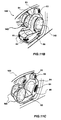
- the protection devices 10, 110, 120, 130, 140, 150 are arranged in a relevant housing 3, 4, 5, 63, 64, 65 of the respective vehicle 1, 100, and are adapted to assume substantially a first resting condition, or deflated condition, hidden in said housing 3, 4, 5, 63, 64, 65, and a second active condition or inflated condition, in which the protection devices 10, 110, 120, 130, 140, 150, 170 come out from the housing 3, 4, 5, 63, 64, 65 as illustrated in Figures 3, 4 , 8A , 9A , 9C , 10, 11A , 11B, 11C .
- the inflation and actuation modes of the protection devices 10, 110, 120, 130, 140, 150, 170 will be described hereinafter in the description.
- the protection device 10 for a motorcycle 1 is arranged in a housing 3 near the handlebar 8, e.g. in a housing 3 obtained in a top portion of the chassis or of the tank; when inflated, the protection device 10 arranges itself in a region in front of the motorcycle user, i.e. on the handlebar, on the tank and on the headlight.
- the protection device 110 for a car 100 is arranged in a housing 4 between the roof and the side panel (wall) of the car; when inflated, the protection device 10 comes out, arranging itself both at the roof and at the door side.
- the protection device 120 for a car 100 is arranged in a housing 5 below the steering wheel 81 and/or the dashboard 82; in an inflated condition, the protection device 120 protects the legs and knees of the user (driver or passenger) from a front impact against the bottom part of the dashboard 82.
- the protection devices 130, 140, 150 for a car 100 are arranged in respective housings 63, 64, 65 obtained respectively on a side of a headrest 83, on a side of the backrest 84 of a seat 86, and on a side of the seating 85 of the seat 86.
- said housings 63, 64, 65 and the respective protection devices 130, 140, 150 are arranged on both sides of the headrest 83 and of the seat 86.
- the protection devices 130, 140, 150 come out of the respective housings 63, 64, 65 and, thanks to their flattened and controlled shape, easily arrange at the user's sides, respectively at the user's head, torso and knees, for a protection of the user from side impacts.
- the protection devices 110, 120, 130, 140, 150 are adapted to "wrap" the user on all sides on which an impact may occur.
- a protection device 170 is illustrated associated to a vehicle, and in particular arranged in a respective housing 171 obtained at the roof of a car 100.
- the protection device 170 When the protection device 170 is inflated, it generally covers the entire roof of the car, active as effective protection for a user above all in case of rollover of the car 100.
- protection devices 10, 110, 120, 130, 140, 150, 170 shown in the figures are exemplary; in fact, it is understood that a vehicle 1, 100 might be provided with only some of said devices, or it might be provided with protection devices having shapes and/or positions different with respect to the ones shown.
- the .protection devices 10, 110, 120, 130, 140, 150, 170 differentiate by overall shape, which is selected depending on the type of specific vehicle to which each of them is associated and according to the region to be protected in the vehicle 1, 100. As for the remaining aspects, the protection devices 10, 110, 120, 130, 140, 150, 170 substantially include the same structural members.
- protection device 10 For this reason, for simplicity's sake in the disclosure, hereinafter reference will be made only to the protection device 10, it being understood that the same description is likewise valid also for protection devices 110, 120, 130, 140, 150, 170.
- the protection device 10 comprises an inflatable member 2, inflatable by introduction of an inflating fluid, e.g. a cold gas, like Helium.
- the inflatable member 2 includes two walls 21, 22 arranged in a spaced apart relationship to form an internal chamber, in the example of material impermeable to said gas. Specifically, walls 21, 22 are associated therebetween, in the example fixed in a gas-tight manner, to form said internal chamber 25.
- the inflatable member 2 also includes a textile structure, so-called double-layer structure, specifically denoted by reference number 31 in Figures 16 to 22 , which is housed in the internal chamber 25.
- the structure 31 includes two meshes 29, 30, in practice forming two layers, opposed therebetween and connected by a plurality of tie members 27.
- the two walls 21, 22 form a case in which the structure including the two meshes 29, 30 is housed.
- each mesh 29, 30 is associated to a respective wall 21, 22.
- tie member 27 it is meant a member or entity having the function of keeping joined or constrained or stationary two or more portions of the inflatable member 2, said tie member being tensioned by tensile stress at least when the inflatable member 2 is in an inflated condition.
- the tie members 27 are of thread-shaped type, and are flexible and inextensible members. Therefore, they are suitably sized so that, when the inflatable member 2 is in a resting condition, they are preferably not subjected to tensioning and are collapsed in the internal chamber 25, whereas when the inflatable member 2 is in an inflated condition they are subjected to tensile stress, as illustrated by way of example in Figures 12 and 13 .
- the tie members 27, besides being of thread-shaped type and flexible, are elastic members. Therefore, the tie members 27 are suitably sized so that, when the inflatable member 2 is in a resting condition, they are preferably not subjected to tensioning, or possibly subjected to a slight tensioning, whereas when the inflatable member 2 is in an inflated condition they are tensioned until reaching a maximum extension and a maximum tensioning.
- the tie members 27 are sketched, merely by way of illustration, with the illustrated density, whereas according to the present disclosure it is advantageous that the tie members 27 be thickly distributed in the inflatable member 2, e.g.
- tie members 27 are distributed substantially homogeneously in the internal chamber 25.
- the tie members 27 are flexible ties and have the shape of threads, and are made e.g. of polyester or polyamide, of a thickness comprised between about 500 and about 1000 decitex (Unit of length of a continuous thread or of a yarn), and have ends 27a, 27b fixed to the respective portions of meshes 29, 30 which they connect.
- each thread 27 includes a bundle of continuous torsion-free fibers coming out from a single point of the respective mesh 29, 30.
- each mesh 29, 30 has an extension such as to nearly entirely line a respective wall 21, 22.
- the inflatable member 2 includes a prefabricated structure, or body, including the two meshes 29, 30, and the two walls 21, 22, or sheets, in the example impermeable to gas; a wall 21 is arranged at the side of one mesh 29 and the other wall 22 is arranged at the side of the other mesh 30.
- the one mesh 29 is stably fixed, in direct contact, to the mesh 30 by glue or by seams, or alike fixings, at their perimeter 281.
- the tie members 27 have opposite ends 27a, 27b stably fixed to the respective mesh 29, 30.
- the fixing at the opposite ends 27a, 27b of the tie members 27 is, e.g., obtained by mere insertion or interlacing of tie members 27 between wefts of the mesh 29, 30.
- the tie members 27 are obtained by a determined number of threads which are fixed, in alternate sections, to the one mesh 29, and consecutively to the other mesh 30.
- each thread is threaded below a weft of the first mesh 29, is curved toward the opposite mesh 30, and is connected in the same manner to the opposite mesh 30, and so on.
- the tie members 27 are connected to the mesh 29, 30 by glue, or by an interlacing or by fastening, or alike fixings.
- the tie members 27 constitute mesh warp or weft portions, which come out from a mesh 29, 30 and interlace in the other mesh 30, 29.
- the structure 31 is obtained by concomitant weaving of the two meshes 29, 30 and connection of the meshes 29, 30 by warp or weft threads of the meshes themselves.
- each tie member 27 is a thread integrally interlaced with, or continuously evolving from, both said first and second mesh 29, 30.
- the thread/tie member 27 comes out from one of said first and second mesh 29, 30 and is integrally interlaced with the other one of said first and second mesh 29, 30.
- the set of the two meshes 29, 30 and of the tie members 27 forms a so-called 3D (three-dimensional) or double-knit fabric.
- meshes 29 and 30 are made of polyester or polyamide.
- the two walls 21, 22, or sheets are made of a sheet of soft and gas-tight material, e.g. of polyamide or polyurethane; the two walls 21, 22 are opposed the one with respect to the other, and perimetrically fixed along their perimetral edges 23, 24.
- the walls 21, 22 are made of a laminate (partially visible in Figure 19 and in Figure 20 ), which is commonly utilized as clothing lining and includes a fabric layer 22a, in the example 100% nylon (representing about 65% b/w of the laminate) and a glue layer 22b, in the example a glue film (representing about 35% b/w of the laminate), e.g. polyurethane glue, distributed on the fabric layer 22a by roller spreading.
- a laminate partially visible in Figure 19 and in Figure 20
- a fabric layer 22a in the example 100% nylon (representing about 65% b/w of the laminate)
- a glue layer 22b in the example a glue film (representing about 35% b/w of the laminate), e.g. polyurethane glue, distributed on the fabric layer 22a by roller spreading.
- each mesh 29, 30 is stably fixed to the surface of the respective wall 21, 22, by a glue film (not visible in Figures 12, 13, 14 and 15 and denoted, e.g., by numbers 15, 16 in Figure 19 ) or by seams, or alike fixings.
- the glue film is arranged in contact with the glue layer 22b of the laminate.
- the hereto-described protection device 10 according to the present disclosure is manufactured as follows.
- a pair of meshes 29, 30 are preliminarily prearranged, to which there are fastened, or otherwise fixed, ends 27a, 27b of the tie members 27, in which the length of said tie members 27 is selected so as to determine a maximum mutual distance D between the meshes 29, 30 corresponding to a maximum local expansion of the inflatable member 2 in an inflated condition.
- the structure 31 thus obtained including the meshes 29, 30 and the ties 27, is included between the two walls 21, 22, i.e. it is arranged inside the chamber 25. Between the meshes 29, 30 it is preferably arranged also a gas canister 60 for inflation.
- the two walls 21, 22 have perimetral portions 23, 24 projecting with respect to the meshes 29, 30.
- the two walls 21, 22 have a surface extension greater than the respective meshes 29, 30, so that the perimetral portions 23, 24 can be connected therebetween without interposition of the meshes 29, 30.
- Said perimetral portions 23, 24 are stably and sealingly connected thereamong, e.g. by heat-sealing, along the perimetral edge 28 so as to contain the structure 31 and make the internal chamber 25 gas-tight.
- the walls 21, 22 are fixed, e.g. by hot-press gluing, to the respective meshes 29, 30.
- the entire external surface of the meshes 29, 30 is fixed to the respective wall 21, 22, In other words, each mesh 29, 30 lines the respective wall 21, 22.
- the method envisages to provide a structure 31 comprising meshes 29, 30 to which are fastened, or otherwise fixed, as indicated above, ends 27a, 27b of tie members 27.
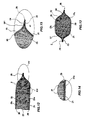
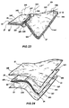
- the structure 31 is illustrated slightly inflated, so as to let understand the presence of the tie members 27, and is indicated with a substantially rectangular profile for simplicity's sake in the explanation.
- the structure 31 has shape and size substantially equivalent to a respective inflatable member 2 to be obtained; moreover, the length of the tie members 27 is selected so as to locally determine a maximum mutual distance D between the meshes 29, 30 corresponding to a maximum local expansion of the respective inflatable member 2 in an inflated condition.
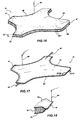
- An edge 44 of the mesh 29 is seamed to a respective edge 46 of the mesh 30 facing thereon (seam line denoted by 47 in Figure 17 ).
- the seaming operation is exemplified with needles 49, however it is highlighted that the seams 47 may be made by a machine or with other equipment conventional for a person skilled in the art.
- the seam line 47 substantially follows the perimeter 281 of the structure 31.
- the seam 47 is a linear seam, made with thread, e.g. of polyamide, and including 2 to 3 stitches/cm (i.e., a seam pitch comprised between about 3 and 5 mm).
- a duct 43 for connection to a deflation valve (not illustrated), is included between the meshes 29, 30.
- a cannula (not illustrated) for connection to the canister 60 may be included between the meshes 29, 30, similarly to the duct 43.
- FIG 18 a detail of the seam 47 is illustrated, in which it appears evident how the seam thread transversally crosses the two meshes 29, 30, tightening them into direct mutual contact.
- the structure 31 is enclosed between the sheets 21, 22 of soft and gas-tight material, e.g. of polyurethane or polyamide, or said above-mentioned laminate, in which the sheets 21, 22 have a surface extension greater than said structure 31.
- soft and gas-tight material e.g. of polyurethane or polyamide, or said above-mentioned laminate, in which the sheets 21, 22 have a surface extension greater than said structure 31.
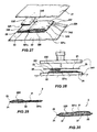
- the sheets 21 and 22 are glued to the respective meshes 29, 30 by means of a glue film, in the example a polyurethane film having a thickness of about 100 pm, denoted by numbers 15, 16, utilizing a hot press 160 (which, e.g., works at temperatures comprised between about 140 °C and 180 °C, preferably at about 150 °C) to foster adhesion and mutual gluing.
- a glue film in the example a polyurethane film having a thickness of about 100 pm, denoted by numbers 15, 16, utilizing a hot press 160 (which, e.g., works at temperatures comprised between about 140 °C and 180 °C, preferably at about 150 °C) to foster adhesion and mutual gluing.
- each glue film 15, 16 is included between a mesh 29, 30 of the structure 31 and the respective sheet 21, 22, as illustrated in Figure 19 .
- each glue film 15, 16 is fixed by hot press 160 to the respective sheet 21, 22 in a first step of the method as illustrated in Figure 21 , to form a composite layer 21', 22' ( Figure 22 ). If the above-mentioned laminate is utilized, gluing occurs by arranging the glue film 15, 16 at the side of the glue layer 22b of the laminate.
- the structure 31 (once the perimetral seam 47 is made) is included between the two composite layers 21', 22'.
- Peripheral edges 123, 124 of the composite layers 21', 22', at which meshes 29, 30 are not enclosed, are directly glued the one on the other in a gas-tight manner.
- the glue film 15, 16 has a high adherence with the laminate (a gluing occurring directly with the glue layer 22b); moreover, the glue film 15, 16 from the other side penetrates the meshes 29, 30, so as to fill the pores of the meshes 29, 30.
- the laminate has a high lightness of weight and, concomitantly, gives high strength to the inflatable member 2.
- the fabric layer 22a of the laminate is an inextensible fabric which opposes any bubble formation during the machining steps.
- the fabric layer 22a being flexible, moreover adjusts to any mutual displacement occurring between the glue film 15, 16 and the laminate itself during the fixing in the press 160.
- the two meshes 29, 30 of the structure 31 are perimetrically fixed directly therebetween, by the abovementioned seam 47.
- the meshes 29, 30 are not connected therebetween merely by the tie members 27, but also perimetrically fixed in direct contact, in the example by perimetral seam 47.
- the seam 47 or an alike perimetral fixing of the meshes 29, 30 entails a significant advantage.
- the inflatable member 2 is subjected to sudden inflation (with inflation times of the order of milliseconds) inside of the inflatable member localized pressure waves occur, even higher than 3 bar.
- the seam 47 serves as a barrier against excessive pressure waves in one or more perimetral zones of the inflatable member 2 where edges 23, 24 of the sheets 21, 22 are joined, and said seam 47 fosters a pressure redistribution and allows to avoid a possible tearing of the sheets 21, 22.
- the seam 47 yields a practical advantage from a manufacturing standpoint as well, since during the machining steps the meshes 29, 30 do not move the one with respect to the other.
- the above-described inflatable member 2 comprises a reinforcing layer 230 ( Figure 26 ) interposed between a wall 22 and the respective mesh 30.
- Said reinforcing layer 230 in the example is comprised of a sheet, or foil of a composite material (e.g., glass fiber or Carbon fiber in a polyurethane matrix), having a thickness of a few millimetres (e.g., 2 mm) and a surface extension smaller than the wall 22 and comparable to the region to be protected.
- Said reinforcing sheet 230 is fixed, e.g. by means of polyurethane glue not visible in Figure 26 , to the respective wall 22 and to the respective mesh 30 between which it is interposed.
- Such a reinforcing layer 230 can be inserted at a suitable time during the above-described steps of manufacturing the inflatable member 2.
- the protection device 10, 110, 120, 130, 140, 150 can be manufactured according to any one shape or outline.
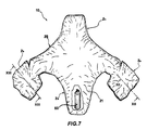
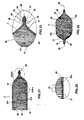
- the inflatable member 2 has a substantially cross-like shape and comprises four regions 2a, 2b, 2c, 2d, of which:
- the regions 2a, 2b, 2c, 2d are pneumatically connected thereamong to form the member 2 and a single internal chamber 25.
- two structures 331 are provided, each including a pair of meshes 29 and 30, 329 and 330 to which there are fastened, or otherwise fixed, ends 27a, 27b of tie members 27.
- Each mesh 29, 30, 329, 330 has shape and sizes substantially equivalent to a respective portion 2a, 2b, 2c, 2d of the inflatable member 2 to be obtained (in Figure 23 it is illustrated, e.g., the pair of meshes 29, 30 intended to form the third portion 2c and the pair of meshes 329, 330 intended to form the first portion 2a and the second portion 2b); moreover, the length of the tie members 27 is selected so as to determine a maximum mutual distance D between the meshes 29 and 30, 329 and 330 of each pair that be corresponding to a maximum local expansion of the respective portion of the inflatable member 2 in an inflated condition.
- An edge 342 of the mesh 29 is seamed to a respective edge 343 of the mesh 329, and likewise the edges 344 and 345 of the respective opposite edges 30, 330 are seamed (seam line denoted by 346 in Figures 23 and 24 ).
- the pairs of meshes 29 and 329, 30 and 330 are joined therebetween, in fact obtaining a single body 331 a, equipped with ties 27, having a surface equal to the sum of the surfaces of the meshes 29 and 329, or 30 and 330, respectively.
- the ties 27 of the first pair of meshes 29 and 30 might have different lengths with respect to the ties 27 of the second pair of meshes 329 and 330, according to the respective portion of inflatable member 2 to be manufactured and its maximum thickness admitted in an inflated condition.
- the single body 331 a thus obtained is enclosed between the walls or sheets 21, 22 ( Figure 24 ) of soft and gas-tight material, e.g. of polyurethane or polyamide, or of the so-called laminate, having a surface extension greater than said single body 331a.
- the sheets 21 and 22 are glued to the respective meshes 29, 30, 329, 330 by means of polyurethane glue, utilizing a hot press 360 (which, e.g., works at temperatures of about 150 °C) to foster adhesion and mutual gluing.
- a reinforcing layer 230 made of a material like, e.g., glass fiber or Carbon fiber in a polyurethane matrix, may be arranged between a mesh 29, 30, 329, 330 and the respective sheet 21, 22; also said reinforcing layer 230 may be glued by means of polyurethane glue 231 ( Figure 28 , under the action of a press 360).
- the sheets 21 and 22 exhibit a certain degree of elasticity, so as to be able to deform during an inflation and allow a differentiated expansion of the first pair of meshes 29, 30 and of the second pair of meshes 329, 330, e.g. in case those have tie members 27 of lengths different thereamong, as illustrated in Figure 30 .
- FIGs 31 to 34 it is illustrated an inflatable member 2 according to a further embodiment.
- the inflatable member 2 comprises at least said two walls 21, 22 made of a sheet of soft and gas-tight material, e.g. of polyamide or polyurethane, or made with the so-called laminate, which are opposed the one with respect to the other, and perimetrically fixed along the abovementioned perimetral edges 23, 24 by a sealing edge, which includes a tape 32, preferably triple-layer, comprising an adhesive layer for adhesion to wall 21, 22 of the inflatable member 2, at least one intermediate polyurethane film, and an external layer of mesh (with an antigraze function for protecting the underlying polyurethane film).
- a sealing edge which includes a tape 32, preferably triple-layer, comprising an adhesive layer for adhesion to wall 21, 22 of the inflatable member 2, at least one intermediate polyurethane film, and an external layer of mesh (with an antigraze function for protecting the underlying polyurethane film).
- the tape 32 is folded in a longitudinal direction to form two opposed hems 33, 34.
- the tape 32 houses, between said opposed hems 33 and 34, the pair of overlapped edges 23, 24 of the walls 21, 22.
- the hems 33, 34 of the tape 32 are seamed therebetween by one or more seam lines 35 so as to fix thereinside also the overlapped edges 23, 24 of the walls 21, 22, as illustrated in Figure 30 .
- a further seam line 36 is provided near the tape 32 to stably join the overlapped edges 23, 24 of the walls 21, 22 and the meshes 29, 30, prior to the fixing of the tape 32.
- the seams 35 and 36 are taped (e.g., heat-taped) according to modes substantially within the reach of a person skilled in the art.
- seams 35, 36 allow to obtain advantages similar to those described in connection to the aforedescribed seam 47.
- the two walls 21, 22 ultimately are two members or sheets of the inflatable member 2, opposed and fixed along the respective perimetral edges 23, 24. In any case, there is nothing to prevent the two walls 21, 22 from being opposite portions of a single sheet folded book-like, and therefore having peripheral edges that extend along a portion of the perimeter and closed thereat by sealing tape.
- this embodiment may be manufactured in conjunction with the aforedescribed embodiment; therefore, there is nothing to prevent the inflatable member 2 from including, besides the direct gluing of the peripheral edges 23, 24 illustrated e.g. in Figure 15 , also the tape 32 at the edge.
- the protection device 10, 110, 120, 130, 140, 150 is adapted to cooperate with suitable means for actuating and inflating, of which in the figures it is illustrated, merely by way of illustration, the Helium canister 60 (cold gas generator), which is arranged, e.g., inside the inflatable member 2.
- suitable means for actuating and inflating of which in the figures it is illustrated, merely by way of illustration, the Helium canister 60 (cold gas generator), which is arranged, e.g., inside the inflatable member 2.
- such means may comprise generators of pyrotechnic-type or hybrid-type gas, or of other typologies known to the state of the art.
- Said inflating means are controlled by a control unit on the basis of a detection of the state of the vehicle/user system; e.g., in case of a motorcycle 1, said control unit may implement a fall prediction system allowing a timely identification of a fall event and a reliable prediction thereof by means of accelerometric sensors integral to the vehicle (or to the user) and an unit for processing the signals produced by the sensors themselves.
- a control unit may implement a fall prediction system allowing a timely identification of a fall event and a reliable prediction thereof by means of accelerometric sensors integral to the vehicle (or to the user) and an unit for processing the signals produced by the sensors themselves.
- the device according to the present disclosure also finds application by utilizing an actuating cable connected to the motorcycle 1, which cable actuates the inflation of the inflatable member 2 following a separation of the user from the motorcycle 1, e.g., following a fall or an impact.
- the abovementioned actuating and inflating means may be integrated in the protection device 10, 110, 120, 130, 140, 150 according to the present disclosure or located externally thereto.
- the inflating means are controlled by a control unit on the basis of a detection of the state of motion and of the deceleration of the car 100, e.g. according to modes already employed for the actuating of known-art airbags.
- the protection device 10 optionally comprises a deflation valve not shown in the drawings, communicating on one side with the internal chamber 25 and on the other side with the outside environment in order to allow deflation of the inflatable member 2 following actuation, and when a protecting action is not required anymore.
- Said deflation valve which normally is in a closed position, is e.g. manually opened by the user, in particular when, owing to a fortuitous actuation or following an impact that has entailed the actuation of the device 10, the user wishes to resume using the vehicle.
- the opening up of the deflation valve causes gas to exit the internal chamber 25 and the member 2 to deflate.
- Tie members 27 having elastic features can assist said deflation, by pulling the respective meshes 29 and 30, 329 and 330 toward each other.
- the actuation of the deflation valve may be controlled by an electronic control unit (not shown), which opens the deflation valve 45 when a preset time interval (e.g., 15 seconds) has elapsed from actuation of the inflating means.
- a preset time interval e.g. 15 seconds
- a deflating cannula is utilized, having a diameter calibrated depending on the deflation time to be obtained.
Landscapes
- Engineering & Computer Science (AREA)
- Mechanical Engineering (AREA)
- Health & Medical Sciences (AREA)
- General Health & Medical Sciences (AREA)
- Physical Education & Sports Medicine (AREA)
- Textile Engineering (AREA)
- Professional, Industrial, Or Sporting Protective Garments (AREA)
- Air Bags (AREA)
Abstract
Claims (31)
- Dispositif de protection (10, 110, 120, 130, 140, 150) comprenant un élément gonflable (2, 2a, 2b, 2c, 2d) comprenant une première paroi (21) et une deuxième paroi (22), opposées entre elles et associées pour former une chambre interne (25), et une structure (31, 331, 331 a) logée dans ladite chambre interne (25), ladite structure (31, 331, 331 a) comprenant une première maille (29, 329) et une deuxième maille (30, 330) opposées entre elles et raccordées par une pluralité d'éléments formant lien (27), dans lequel ladite première maille (29, 329) est associée à la première paroi (21) et ladite deuxième maille (30, 330) est associée à la deuxième paroi (22), et dans lequel ledit dispositif (10, 110, 120, 130, 140, 150, 170) est un dispositif pour la protection d'un utilisateur d'un véhicule (1, 100) et est adapté pour être associé audit véhicule (1, 100).
- Dispositif de protection (10, 110, 120, 130, 140, 150, 170) selon la revendication 1, dans lequel lesdits éléments formant lien (27) sont de type flexible.
- Dispositif de protection (10, 110, 120, 130, 140, 150, 170) selon la revendication 1 ou 2, dans lequel lesdits éléments formant lien (27) ont la forme de fils.
- Dispositif de protection (10, 110, 120, 130, 140, 150, 170) selon l'une quelconque des revendications 1 à 3, dans lequel lesdits éléments formant lien (27) sont répartis avec une densité de surface d'au moins un élément formant lien (27) par cm2 de surface de la première maille (29, 329) et de la deuxième maille (30, 330) respectives.
- Dispositif de protection (10, 110, 120, 130, 140, 150, 170) selon l'une quelconque des revendications 1 à 4, dans lequel lesdits éléments formant lien (27) ont chacun une extrémité (27a) entrelacée de manière continue avec l'une parmi ladite première maille (29, 329) et la deuxième maille (30, 330) et une extrémité opposée (27b) entrelacée de manière continue avec l'autre parmi ladite première maille (29, 329) et la deuxième maille (30, 330).
- Dispositif de protection (10, 110, 120, 130, 140, 150, 170) selon l'une quelconque des revendications 1 à 5, dans lequel la première maille (29, 329) et la deuxième maille (30, 330) sont assemblées entre elles en contact direct le long de bords périmétraux (23, 24, 123, 124, 347).
- Dispositif de protection (10, 110, 120, 130, 140, 150, 170) selon l'une quelconque des revendications 1 à 6, comprenant une couture périmétrale (35, 36, 47, 348) adaptée pour raccorder directement ladite première maille (29, 329) avec ladite deuxième maille (30, 330).
- Dispositif de protection (10, 110, 120, 130, 140, 150, 170) selon la revendication 7, dans lequel ladite couture (47, 348) suit un profil périmétral (23, 24, 123, 124, 347) de ladite première maille (29, 329) et de ladite deuxième maille (30, 330).
- Dispositif de protection (10, 110, 120, 130, 140, 150, 170) selon la revendication 7 ou 8, dans lequel ladite couture (35, 36, 47, 348) est linéaire.
- Dispositif de protection (10, 110, 120, 130, 140, 150, 170) selon l'une quelconque des revendications 1 à 9, dans lequel chacune parmi ladite première paroi (21) et la deuxième paroi (22) est un stratifié comprenant une première couche (22a) et une deuxième couche (22b).
- Dispositif de protection (10, 110, 120, 130, 140, 150, 170) selon la revendication 10, dans lequel ladite première couche est un tissu (22a) et ladite deuxième couche (22b) est une couche de colle.
- Dispositif de protection (10, 110, 120, 130, 140, 150, 170) selon la revendication 11, dans lequel ladite première couche est un tissu en nylon (22a) et ladite deuxième couche (22b) est une couche de colle de polyuréthane.
- Dispositif de protection (10, 110, 120, 130, 140, 150, 170) selon l'une quelconque des revendications 1 à 12, dans lequel ladite première paroi (21) et ladite deuxième paroi (22) sont fixées entre elles le long de bords périmétraux (28, 23, 24) respectifs.
- Dispositif de protection (10, 110, 120, 130, 140, 150, 170) selon la revendication 13, dans lequel chacune parmi ladite première paroi (21) et la deuxième paroi (22) a une extension de surface supérieure à la première maille (29) ou à la deuxième maille (30) respective, et dans lequel les bords périphériques (23, 24, 123, 124, 347) de ladite première paroi (21) et de ladite deuxième paroi (22), faisant saillie respectivement de la première maille (29, 329) et de la deuxième maille (30, 330), sont assemblés de manière étanche entre eux.
- Dispositif de protection (10, 110, 120, 130, 140, 150, 170) selon l'une quelconque des revendications 1 à 14, dans lequel entre chacune parmi ladite première maille (29, 329) et la deuxième maille (30, 330) et la première paroi (21) ou la deuxième paroi (22) respective, on intercale une couche de colle (15, 16) respective.
- Dispositif de protection (10, 110, 120, 130, 140, 150, 170) selon la revendication 15, dans lequel la couche de colle est une pellicule de colle (15, 16).
- Dispositif de protection (10, 110, 120, 130, 140, 150, 170) selon l'une quelconque des revendications 1 à 16, comprenant une pluralité desdites structures (331) raccordées entre elles afin de former un corps unique (331 a), et logées dans la chambre interne (25).
- Dispositif de protection (10, 110, 120, 130, 140, 150, 170) selon l'une quelconque des revendications 1 à 17, comprenant en outre une couche de renforcement (230) associée à une partie superficielle (21, 22) respective dudit élément gonflable (2, 2a, 2b, 2c, 2d).
- Dispositif de protection (10, 110, 120, 130, 140, 150, 170) selon la revendication 18, dans lequel ladite couche de renforcement (230) est intercalée entre l'une parmi ladite première maille (29, 329) ou la deuxième maille (30, 330) et la première paroi (21) ou la deuxième paroi (22) respective.
- Dispositif de protection (10, 110, 120, 130, 140, 150, 170) selon l'une quelconque des revendications 1 à 19, comprenant des moyens (60) pour actionner et/ou gonfler ledit élément gonflable (2, 2a, 2b, 2c, 2d).
- Véhicule (1, 100) comprenant un boîtier (3, 4, 5, 63, 64, 65) et un dispositif de protection (10, 110, 120, 130, 140, 150, 170) selon l'une quelconque des revendications 1 à 20, ledit dispositif de protection (10, 110, 120, 130, 140, 150, 170) étant agencé dans ledit boîtier (3, 4, 5, 63, 64, 65).
- Procédé pour fabriquer un dispositif de protection (10, 110, 120, 130, 140, 150, 170), dans lequel ledit dispositif (10, 110, 120, 130, 140, 150, 170) est un dispositif pour la protection d'un utilisateur d'un véhicule (1, 100) et est adapté pour être associé audit véhicule (1, 100), dans lequel le procédé comprend les étapes consistant à :prévoir une première paroi (21) et une deuxième paroi (22) et les agencer en relation espacée afin de former une chambre interne (25) ;loger dans la chambre interne (25), une structure (31, 331, 331 a) comprenant une première maille (29, 329) et une deuxième maille (30, 330) opposées entre elles et raccordées par une pluralité d'éléments formant lien (27) ;associer ladite première maille (29, 329) à la première paroi (21) et ladite deuxième maille (30, 330) à la deuxième paroi (22) ;associer de manière périmétrale entre elles ladite première paroi (21) et la deuxième paroi (22), afin d'enfermer ladite chambre interne (25).
- Procédé selon la revendication 22, comprenant une étape consistant à inclure une pellicule de colle (15, 16) entre chacune parmi ladite première maille (29) et la deuxième maille (30) et la première paroi (21) et la deuxième paroi (22) respectives.
- Procédé selon la revendication 23, dans lequel chacune parmi ladite première paroi (21) et la deuxième paroi (22) est un stratifié comprenant une première couche (22a) et une deuxième couche (22b), dans lequel ladite deuxième couche (22b) est agencée en contact avec ladite pellicule de colle (15, 16).
- Procédé selon la revendication 24, dans lequel ladite première couche (22a) est une couche de tissu, et ladite deuxième couche (22b) est une couche de colle.
- Procédé selon la revendication 25, dans lequel ladite première couche (22a) est un tissu en nylon et ladite deuxième couche (22b) est une couche de colle de polyuréthane.
- Procédé selon l'une quelconque des revendications 22 à 26, dans lequel, avant de loger ladite structure (31, 331, 331 a) dans la chambre interne (25) entre ladite première paroi (21) et ladite deuxième paroi (22), ladite première maille (29, 329) est fixée de manière périmétrale en contact direct avec la deuxième maille (30, 330).
- Procédé selon l'une quelconque des revendications 22 à 26, dans lequel, avant de loger ladite structure (31, 331, 331 a) dans la chambre interne (25) entre ladite première paroi (21) et la deuxième paroi (22), ladite première maille (29, 329) est cousue de manière périphérique avec la deuxième maille (30, 330).
- Procédé selon l'une quelconque des revendications 22 à 28, dans lequel ladite première paroi (21) et ladite deuxième paroi (22) sont réalisées afin d'avoir une extension de surface supérieure à la première maille (29, 329) ou la deuxième maille (30, 330), et dans lequel les bords périphériques (23, 24, 123, 124, 347) de ladite première paroi (21) et de la deuxième paroi (22) font saillie respectivement à partir de chacune parmi ladite première maille (29, 329) et la deuxième maille (30, 330) et sont assemblées de manière étanche entre elles.
- Procédé selon l'une quelconque des revendications 22 à 29, comprenant les étapes consistant à :prévoir une pluralité desdites structures (331) et les agencer de manière adjacente entre elles ;assembler entre elles le long des bords (342, 343) respectifs, les premières mailles (29, 329) adjacentes de chacune desdites structures (331) ;assembler parmi ces dernières le long des bords (344, 345) respectifs les deuxièmes mailles (30, 330) adjacentes de chacune desdites structures (331),inclure la réunion (331 a) de toutes les structures (331) entre une première paroi (21) et une deuxième paroi (22).
- Procédé selon l'une quelconque des revendications 22 à 30, dans lequel une couche de renforcement (230) est intercalée entre une paroi (21, 22) et une maille (29, 30, 329, 330) adjacente à cette dernière.
Applications Claiming Priority (3)
| Application Number | Priority Date | Filing Date | Title |
|---|---|---|---|
| ITRM2008A000656A IT1392306B1 (it) | 2008-12-09 | 2008-12-09 | Dispositivo di protezione personale ed indumento incorporante tale dispositivo. |
| ITVR2009A000078A IT1394657B1 (it) | 2009-05-29 | 2009-05-29 | Dispositivo di protezione includente un elemento gonfiabile. |
| PCT/IB2009/055507 WO2010067285A1 (fr) | 2008-12-09 | 2009-12-04 | Dispositif de protection comprenant un élément gonflable |
Publications (2)
| Publication Number | Publication Date |
|---|---|
| EP2373524A1 EP2373524A1 (fr) | 2011-10-12 |
| EP2373524B1 true EP2373524B1 (fr) | 2012-06-20 |
Family
ID=41716628
Family Applications (3)
| Application Number | Title | Priority Date | Filing Date |
|---|---|---|---|
| EP20090807552 Active EP2373190B1 (fr) | 2008-12-09 | 2009-12-04 | Dispositif de protection comprenant un élément gonflable |
| EP09797168.3A Active EP2373189B2 (fr) | 2008-12-09 | 2009-12-04 | Dispositif de protection personnelle et vêtement comportant un tel dispositif |
| EP20090797166 Active EP2373524B1 (fr) | 2008-12-09 | 2009-12-04 | Dispositif de protection comprenant un élément gonflable |
Family Applications Before (2)
| Application Number | Title | Priority Date | Filing Date |
|---|---|---|---|
| EP20090807552 Active EP2373190B1 (fr) | 2008-12-09 | 2009-12-04 | Dispositif de protection comprenant un élément gonflable |
| EP09797168.3A Active EP2373189B2 (fr) | 2008-12-09 | 2009-12-04 | Dispositif de protection personnelle et vêtement comportant un tel dispositif |
Country Status (5)
| Country | Link |
|---|---|
| US (3) | US9027170B2 (fr) |
| EP (3) | EP2373190B1 (fr) |
| JP (3) | JP5486607B2 (fr) |
| ES (3) | ES2388411T3 (fr) |
| WO (3) | WO2010067285A1 (fr) |
Cited By (2)
| Publication number | Priority date | Publication date | Assignee | Title |
|---|---|---|---|---|
| IT201900023985A1 (it) | 2019-12-13 | 2021-06-13 | D Air Lab S R L | Dispositivo di protezione e metodo per realizzare tale dispositivo di protezione |
| IT201900023961A1 (it) | 2019-12-13 | 2021-06-13 | D Air Lab S R L | Dispositivo di protezione e metodo per realizzare tale dispositivo di protezione |
Families Citing this family (62)
| Publication number | Priority date | Publication date | Assignee | Title |
|---|---|---|---|---|
| EP2373190B1 (fr) | 2008-12-09 | 2012-05-30 | Dainese S.p.A. | Dispositif de protection comprenant un élément gonflable |
| EP2373188B1 (fr) | 2008-12-09 | 2012-02-08 | Dainese S.p.A. | Vêtement conçu pour être associé à un dispositif destiné à la protection personnelle d'un utilisateur |
| JP5363649B2 (ja) * | 2009-06-05 | 2013-12-11 | アルパインスターズ リサーチ ソシエタ ア レスポンサビリタ リミタータ | オートバイ乗りのためのエアーバッグシステム |
| CN103153102B (zh) * | 2010-09-29 | 2015-04-08 | 霍丁斯瑞典有限公司 | 适于保护头部的安全气囊 |
| US20120246788A1 (en) * | 2011-03-28 | 2012-10-04 | Harrell Jeremy L | Multipurpose Cooling and Trauma Attenuating Devices and Associated Methods |
| ITVR20110135A1 (it) * | 2011-06-30 | 2012-12-31 | Dainese Spa | Dispositivo di protezione. |
| ITTV20110108A1 (it) * | 2011-07-25 | 2013-01-26 | Antonio Marzotto | Dispositivo di protezione 3d monouso con funzione air-bag, per indumento sportivo, e metodo di produzione |
| EP2594438A1 (fr) * | 2011-11-16 | 2013-05-22 | Volvo Car Corporation | Dispositif gonflable et face avant de véhicule déployable avec dispositif gonflable |
| US20130131930A1 (en) * | 2011-11-22 | 2013-05-23 | Yat Wai Edwin Kwong | Strollers for preventing harm to an infant when an accidental event occurs to the stroller |
| ITVR20120005A1 (it) * | 2012-01-11 | 2013-07-12 | Dainese Spa | Dispositivo di protezione personale ed indumento incorporante tale dispositivo. |
| ITVR20120238A1 (it) | 2012-12-06 | 2014-06-07 | Dainese Spa | Indumento atto ad essere associato ad un dispositivo per la protezione personale di un utilizzatore. |
| USD738576S1 (en) | 2013-01-14 | 2015-09-08 | Jeremy L. Harrell | Inflatable pad pattern |
| USD743633S1 (en) | 2013-01-14 | 2015-11-17 | Jeremy L. Harrell | Inflatable pad pattern |
| USD731122S1 (en) | 2013-01-14 | 2015-06-02 | Jeremy L. Harrell | Inflatable pad |
| USD738577S1 (en) | 2013-01-14 | 2015-09-08 | Jeremy L. Harrell | Inflatable pad pattern |
| US9986777B2 (en) * | 2013-03-04 | 2018-06-05 | Tate Technology, Llc | Balaclava hood system |
| EP2994002B1 (fr) * | 2013-05-06 | 2018-04-25 | Dainese S.p.A. | Dispositif de protection individuelle |
| ITVR20130106A1 (it) * | 2013-05-06 | 2014-11-07 | Dainese Spa | Dispositivo di protezione personale. |
| ITVR20130138A1 (it) * | 2013-06-12 | 2014-12-13 | Dainese Spa | Dispositivo di protezione personale. |
| ITVR20130136A1 (it) | 2013-06-12 | 2014-12-13 | Dainese Spa | Dispositivo di protezione personale. |
| US9045108B1 (en) | 2014-06-04 | 2015-06-02 | Toyota Motor Engineering & Manufacturing North America, Inc. | Airbag reinforcement material at an airbag gas inlet |
| US9016717B1 (en) * | 2014-06-19 | 2015-04-28 | Toyota Motor Engineering & Manufacturing North America, Inc. | Curtain airbag for vertical and angular motion of occupant in rollover |
| DE202015000764U1 (de) * | 2015-02-03 | 2016-05-10 | Dalphi Metal Espana, S.A. | Aufblasbarer Gassack eines Vorhangairbags, Gassackmodul, Fahrzeuginsassenrückhaltesystem und Vorhangairbag |
| ITVR20150074A1 (it) * | 2015-05-06 | 2016-11-06 | Dainese Spa | Dispositivo di protezione e metodo per realizzare tale dispositivo di protezione |
| ITUB20152924A1 (it) | 2015-08-07 | 2017-02-07 | Dainese Spa | Dispositivo di rilevazione di impatto |
| ITUB20155497A1 (it) | 2015-11-11 | 2017-05-11 | Dainese Spa | Dispositivo di protezione |
| EP3178754B1 (fr) * | 2015-12-07 | 2021-06-23 | Sartorius Stedim Fmt Sas | Conteneur gonflable de transport d'un fluide biopharmaceutique et système et procédé mettant en oeuvre un tel conteneur |
| US10897938B2 (en) * | 2016-01-27 | 2021-01-26 | Davenport Saf-T Systems LLC | Wearable device for fall injury mitigation |
| US9873401B2 (en) * | 2016-02-26 | 2018-01-23 | Autoliv Asp, Inc. | Airbag fabric including apertures and methods of forming the same |
| DE202016001546U1 (de) | 2016-03-01 | 2016-06-20 | Davide Amato | Ultraleichtes Airbag-System bestehend aus zwei Komponenten am Rücken und Handgelenk, zum Schutz des Oberkörpers, insbesondere des Schlüsselbeins, für alle Sportarten, insbesondere Fahrradfahren |
| US10849383B2 (en) * | 2016-03-18 | 2020-12-01 | Stephen Sciortino | Wearable impact protection and force channeling device |
| ITUA20161999A1 (it) | 2016-03-24 | 2017-09-24 | Dainese Spa | Dispositivo di protezione |
| US9949516B2 (en) * | 2016-08-01 | 2018-04-24 | Joshua R&D Technologies, LLC | Interactive helmet system and method |
| US9932012B1 (en) * | 2016-12-19 | 2018-04-03 | Ford Global Technologies, Llc | Inner carrier and back panel having alternating trim and side airbag attachments |
| IT201700036571A1 (it) * | 2017-04-03 | 2018-10-03 | Dainese Spa | Dispositivo di protezione |
| ES2787015T3 (es) | 2017-05-16 | 2020-10-14 | D Air Lab S R L | Asiento provisto de un dispositivo de protección |
| IT201700070699A1 (it) | 2017-06-23 | 2018-12-23 | Dainese Spa | Dispositivo di protezione |
| IT201700084843A1 (it) | 2017-07-25 | 2019-01-25 | Dainese Spa | Dispositivo di protezione |
| US10806280B2 (en) * | 2017-09-15 | 2020-10-20 | Bruce Li | Removable neck support pillow for garment |
| EP3482646B1 (fr) | 2017-11-10 | 2020-07-08 | LD 72 S.r.l. | Dispositif de protection du genou |
| DE102017010533B4 (de) * | 2017-11-14 | 2021-11-04 | Michael Wagner | Protektoreinrichtung zum Schutz der Halswirbelsäule und Schutzausrüstung hiermit |
| EP4480336A3 (fr) | 2017-12-18 | 2025-03-05 | Dainese S.p.A. | Vêtement de protection d'un utilisateur comprenant un élément gonflable |
| US12161577B2 (en) | 2018-11-20 | 2024-12-10 | Tate Technology, Llc | Inflatable cervical collar neck system |
| EP3718608B1 (fr) * | 2019-04-01 | 2021-11-17 | Volvo Car Corporation | Structure gonflable |
| EP3718751A1 (fr) * | 2019-04-01 | 2020-10-07 | Volvo Car Corporation | Procédé defabrication d'une structure gonflable |
| US11014619B2 (en) * | 2019-09-10 | 2021-05-25 | GM Global Technology Operations LLC | Internally-tensioned inflatable device for active flow control drag reduction or stability increase |
| IT201900016553A1 (it) | 2019-09-17 | 2021-03-17 | Dainese Spa | Dispositivo di protezione e procedimento per realizzare tale dispositivo di protezione |
| IT201900016538A1 (it) | 2019-09-17 | 2021-03-17 | Dainese Spa | Dispositivo di protezione e uso di detto dispositivo di protezione |
| US12012065B2 (en) * | 2019-12-13 | 2024-06-18 | D-Air Lab S.r.l. | Protective device and method for making said protective device |
| IT202000000340A1 (it) | 2020-01-10 | 2021-07-10 | Dainese Spa | Dispositivo di protezione |
| CN113428106B (zh) * | 2020-03-04 | 2023-05-05 | 宁波均胜汽车安全系统有限公司 | 框架式空心安全气囊和安全气囊装置 |
| IT202000011743A1 (it) * | 2020-05-20 | 2021-11-20 | Dainese Spa | Indumento includente un dispositivo di protezione |
| IT202000015454A1 (it) * | 2020-06-26 | 2021-12-26 | Alpinestars Res Spa | Dispositivo di protezione indossabile |
| IT202000031358A1 (it) | 2020-12-18 | 2022-06-18 | Alpinestars Res Spa | Dispositivo di protezione indossabile |
| JP7456402B2 (ja) * | 2021-02-26 | 2024-03-27 | 豊田合成株式会社 | 着用エアバッグ装置 |
| IT202100031829A1 (it) | 2021-12-20 | 2023-06-20 | D Air Lab S R L | Dispositivo di protezione personale |
| IT202200010424A1 (it) | 2022-05-19 | 2023-11-19 | D Air Lab S R L | Dispositivo di protezione personale |
| IT202200011039A1 (it) * | 2022-05-26 | 2023-11-26 | Alpinestars Res Spa | Dispositivo di protezione indossabile |
| IT202200021045A1 (it) * | 2022-10-12 | 2024-04-12 | Dainese Spa | Dispositivo di collegamento a boccola e dispositivo di protezione personale includente detto dispositivo di collegamento a boccola |
| DE102022129315B4 (de) | 2022-11-07 | 2025-01-02 | Autoliv Development Ab | Aufblasbare schutzvorrichtung |
| EP4670544A1 (fr) * | 2024-06-27 | 2025-12-31 | D-Air Lab S.r.l. | Dispositif de protection du cou, procédé de fabrication de celui-ci, vêtement comprenant ledit dispositif de protection |
| EP4702862A1 (fr) | 2024-08-30 | 2026-03-04 | D-Air Lab S.r.l. | Appareil de protection portable et personnalisable |
Family Cites Families (146)
| Publication number | Priority date | Publication date | Assignee | Title |
|---|---|---|---|---|
| US1172197A (en) | 1911-06-09 | 1916-02-15 | Charles P Cook | Hot-water bag. |
| US2657716A (en) | 1950-10-28 | 1953-11-03 | Wingfoot Corp | Inflatable fabric segment of curved configuration |
| US3422458A (en) | 1963-08-06 | 1969-01-21 | Us Air Force | Flexible structure for pressurized garments |
| DE2258852A1 (de) | 1972-12-01 | 1974-06-12 | Albert Schuster | Pneu - skischuh |
| US3930667A (en) | 1975-02-14 | 1976-01-06 | Osuchowski Andrew J | Inflatable garment for crash protection |
| DE2626765A1 (de) | 1976-06-15 | 1977-12-22 | Brian J Littler | Schutzkleidung fuer rennfahrer, insbesondere fuer motorradfahrer |
| US4089065A (en) * | 1976-10-28 | 1978-05-16 | Mcgee Michael Henry | Clothing for providing protection against forceful impact |
| DE7837841U1 (de) | 1978-12-21 | 1982-02-17 | Metzeler Kautschuk GmbH, 8000 München | Aufblasbares Element für eine Schuhsohle |
| US4300894A (en) | 1979-12-03 | 1981-11-17 | General Motors Corporation | Method of making L-shaped inflatable restraint cushion |
| CH637547A5 (fr) | 1980-07-15 | 1983-08-15 | Michel Steiner | Dispositif de protection d'un utilisateur, notamment un motocycliste. |
| JPH032961B2 (fr) | 1980-10-27 | 1991-01-17 | Arufuretsuto Kuroisu | |
| AT369084B (de) | 1980-12-16 | 1982-12-10 | Pehr Holding Ges M B H | Leichtbauelemente |
| US4397046A (en) * | 1981-06-29 | 1983-08-09 | Lacoray S.A. | Protecting device especially for motor-cyclists |
| US4507801A (en) | 1982-09-07 | 1985-04-02 | Doc-K Protective Equipment, Inc. | Protective garment |
| DE8620408U1 (de) | 1986-07-30 | 1986-11-13 | Fischer, Herwig, 41844 Wegberg | Vorrichtung zum Schutz von Personen, insbesondere Kraftradfahrern, gegen Sturzverletzungen |
| US4737994A (en) | 1986-12-30 | 1988-04-19 | Galton Harry A | Garment for protecting wearer against bone fracture |
| JPS6429053U (fr) | 1987-08-17 | 1989-02-21 | ||
| GB2251368B (en) | 1988-02-05 | 1992-10-14 | Rudy Marion F | Improvements in and relating to pressurised envelopes |
| US5083361A (en) | 1988-02-05 | 1992-01-28 | Robert C. Bogert | Pressurizable envelope and method |
| DE3903216A1 (de) * | 1989-02-03 | 1990-08-09 | Parabeam Bv | Airbag |
| DE4007862A1 (de) | 1989-03-25 | 1990-09-27 | Parabeam Ind & Handels Bv | Faltenbalg |
| US4966389A (en) | 1989-03-28 | 1990-10-30 | Juichiro Takada | Inflatable air bag for protection of a vehicle occupant |
| US4977623A (en) | 1989-05-01 | 1990-12-18 | Demarco Vincent J | User wearable inflatable garment |
| US5178938A (en) | 1989-09-25 | 1993-01-12 | The B. F. Goodrich Company | Composition for adhesion of polyurethane-coated nylon fabrics |
| JP2945039B2 (ja) | 1989-10-24 | 1999-09-06 | タカタ株式会社 | エアバッグ |
| US5152018A (en) | 1989-12-15 | 1992-10-06 | Cascade Designs, Inc. | Batting filled self inflatable body |
| GB2243119A (en) | 1990-03-10 | 1991-10-23 | Woodville Polymer Eng | A vehicle air bag with inflation control straps |
| GB2252083A (en) | 1991-01-22 | 1992-07-29 | Dowty Woodville Polymer Ltd | Heat resistant vehicle crash bag. |
| FR2674761A1 (fr) | 1991-04-02 | 1992-10-09 | Lievain Oscar | Combinaison de protection contre les avalanches. |
| FR2677856A1 (fr) | 1991-06-20 | 1992-12-24 | Demarais Yves | Vetement de protection. |
| US5500952A (en) | 1994-10-28 | 1996-03-26 | Keyes; Marshall J. | Hip inflatable protection device |
| US5781936A (en) | 1995-03-22 | 1998-07-21 | Alaloof; Jacob | Projection system for the rider of a non-enclosed vehicle and vehicle incorporating same |
| GB2302642B (en) * | 1995-06-22 | 1997-12-24 | Edward Emanuel Ellul | Air vest protector |
| US6032299A (en) | 1995-10-30 | 2000-03-07 | Welsh; Nicole | Jacket for reducing spinal and compression injuries associated with a fall from a moving vehicle |
| DE19640658C2 (de) | 1996-10-02 | 2000-06-29 | Siegfried Rometsch | Schutzeinrichtung für Benutzer von Zweiradfahrzeugen |
| JP3731266B2 (ja) | 1996-10-24 | 2006-01-05 | 豊田合成株式会社 | 側部用エアバッグの製造方法 |
| JP3229950B2 (ja) * | 1996-12-26 | 2001-11-19 | 豪 景山 | 人体用衝撃吸収補助具 |
| JP3658139B2 (ja) * | 1997-05-15 | 2005-06-08 | 株式会社ハイビックス | 流体圧入プレート及びその製造方法 |
| US5941866A (en) | 1997-07-25 | 1999-08-24 | Bracco Research Usa | Means to maintain configuration of flexible medical container |
| DE19732211A1 (de) | 1997-07-26 | 1999-01-28 | Beluga Tauchsport Gmbh | Anwendung von Abstandsgewirken |
| US5945359A (en) | 1997-08-18 | 1999-08-31 | Milliken & Company | Weft inserted warp knit air bag fabric |
| US5937447A (en) | 1997-10-06 | 1999-08-17 | Howell; William J. | Protective garment |
| US6991693B2 (en) | 1997-12-24 | 2006-01-31 | Saint-Gobain Bayform America, Inc. | Screen cloth insertion apparatus and method |
| DE19811616A1 (de) * | 1998-03-17 | 1999-09-23 | Bayerische Motoren Werke Ag | Airbag mit Fangbändern |
| JPH11268605A (ja) | 1998-03-25 | 1999-10-05 | Mazda Motor Corp | 自動車のエアバッグ装置 |
| US6170871B1 (en) | 1998-06-24 | 2001-01-09 | Breed Automotive Technology, Inc. | Inflatable trim panel assembly for safety restraint systems |
| US6355123B1 (en) | 1998-07-06 | 2002-03-12 | Methode Electronics, Inc. | Roll-over air bag having a reinforced perimeter seal and associated method for producing a flat reinforced seal in a roll-over air bag |
| US6112327A (en) * | 1998-07-07 | 2000-09-05 | Swimfree, Llc | Swimwear with floatation members |
| US6152481A (en) | 1998-08-03 | 2000-11-28 | Delphi Technologies, Inc. | Side restraint assembly |
| EP0994207B1 (fr) | 1998-10-14 | 2004-01-02 | Malden Mills Industries, Inc. | Etoffe en tricot tridimensionel pour chaussures et sacs à dos |
| JP3726518B2 (ja) | 1998-11-18 | 2005-12-14 | タカタ株式会社 | エアバッグ |
| JP2000185109A (ja) * | 1998-12-21 | 2000-07-04 | Safety:Kk | 緊急用エア―バック付緩衝胴衣具 |
| US6194229B1 (en) | 1999-01-08 | 2001-02-27 | Micron Technology, Inc. | Method for improving the sidewall stoichiometry of thin film capacitors |
| ES2230845T3 (es) * | 1999-02-27 | 2005-05-01 | Andrew Robert England Kerr | Traje de proteccion. |
| US6220629B1 (en) | 1999-04-21 | 2001-04-24 | Breed Automotive Technology, Inc. | Cushion with increased seam strength and method of assembly |
| US6753275B2 (en) | 1999-06-07 | 2004-06-22 | Bradford Industries, Inc. | Laminated multi-layered woven textile fabrics for use in air holding vehicle restraint systems |
| US6740607B2 (en) | 1999-06-07 | 2004-05-25 | Bradford Industries, Inc. | Substrate with stretch and heat sealing properties to make a multidirectional restraint module design |
| US6734125B2 (en) * | 1999-06-07 | 2004-05-11 | Bradford Industries, Inc. | Laminated multi-denier mixed fabrics for use in inflatable vehicle restraint systems |
| US6770578B2 (en) † | 1999-06-07 | 2004-08-03 | Bradford Industries, Inc. | Laminated textile fabrics for use in air holding vehicle restraint systems |
| US6458724B1 (en) | 1999-06-07 | 2002-10-01 | Bradford Industries, Inc. | Coated multi-layered woven textile fabrics for use in air-holding vehicle restraint system |
| US6239046B1 (en) | 1999-06-07 | 2001-05-29 | Bradford Industries, Inc. | Polysiloxane coated fabrics for use in air bags |
| US6734123B2 (en) | 1999-06-07 | 2004-05-11 | Bradford Industries, Inc. | Polyurethane coated fabrics for use in air-holding vehicle restraint systems |
| US6701971B1 (en) | 1999-06-17 | 2004-03-09 | Mililken & Company | Low permeability side curtain airbag cushions having extremely low coating levels |
| GB2352162A (en) | 1999-07-19 | 2001-01-24 | John Francis Robinson | Motorcyclists protective wear |
| US6301714B1 (en) | 1999-10-05 | 2001-10-16 | Keun Bae Son | Upper garment with an inflatable collar |
| US6422597B1 (en) | 1999-11-12 | 2002-07-23 | Delphi Technologies, Inc. | Variable profile air bag restraint |
| US6350709B1 (en) | 1999-11-30 | 2002-02-26 | Bradford Industries, Inc. | Heat sealable coated textile fabric for inflatable vehicle restraint systems |
| DE20003097U1 (de) | 2000-02-19 | 2000-08-17 | Textilforschungsinstitut Thüringen-Vogtland e.V., 07973 Greiz | Flammhemmendes dreidimensionales textiles Maschengebilde |
| US6435553B1 (en) | 2000-03-20 | 2002-08-20 | Breed Automotive Technology, Inc. | Air bag and method of seam assembly for minimizing gas leakage |
| DE10026714A1 (de) | 2000-05-30 | 2001-12-13 | Hueck Folien Gmbh | Verbundfolie, Verfahren zu ihrer Herstellung und ihre Verwendung |
| US20020029546A1 (en) | 2000-06-29 | 2002-03-14 | Gould Lisa M. | Method for disposing of a soiled disposable diaper |
| JP2002020907A (ja) * | 2000-07-10 | 2002-01-23 | Kenji Takeuchi | 自動膨張式胴衣 |
| US20020122908A1 (en) † | 2000-08-30 | 2002-09-05 | Shulong Li | Abrasion and/or puncture resistant fabrics, airbag cushions, and methods |
| DE20021066U1 (de) | 2000-12-13 | 2001-05-03 | Trw Repa Gmbh | Aufblasbarer Seiten-Gassack für ein Fahrzeuginsassen-Schutzsystem |
| US6920647B2 (en) | 2000-12-22 | 2005-07-26 | Izaak A. Ulert | Hip protector |
| WO2002055347A1 (fr) | 2001-01-09 | 2002-07-18 | Kolon Industries, Inc | Airbag sous forme de rideau lateral et son procede de fabrication |
| SE523328C2 (sv) | 2001-02-06 | 2004-04-13 | Fov Fabrics Ab | Uppblåsbar luftsäck och förfarande att tillverka sådan |
| FR2822028A1 (fr) | 2001-03-19 | 2002-09-20 | Elez Jose Morcillo | Dispositif de securite integre dans un vetement notamment un anorak gonflable, une veste gonflable, un blouson gonflable ou combinaison de survie gonflable |
| US20020140218A1 (en) † | 2001-03-29 | 2002-10-03 | Beasley Alonzo W. | One-piece woven airbag |
| US6502853B2 (en) * | 2001-04-17 | 2003-01-07 | Milliken & Company | Low permeability airbag and method |
| JP2002331894A (ja) * | 2001-05-09 | 2002-11-19 | Matsushita Electric Ind Co Ltd | エアバッグ装置および車両事故検出装置 |
| JP2002362280A (ja) | 2001-06-01 | 2002-12-18 | Toyoda Gosei Co Ltd | 頭部保護エアバッグ装置 |
| US6908528B2 (en) | 2001-08-02 | 2005-06-21 | Reeves Brothers, Inc. | Laminate composite fabric |
| DE10141437A1 (de) * | 2001-08-23 | 2003-02-20 | Breed Automotive Tech | Luftsack und Verfahren zum Herstellen eines Luftsackes |
| US6857136B1 (en) * | 2002-09-27 | 2005-02-22 | Simula, Inc. | Inflatable head and neck support collar |
| US6712389B2 (en) * | 2002-02-01 | 2004-03-30 | Trw Vehicle Safety Systems Inc. | Air bag with tether |
| US6659046B2 (en) | 2002-02-11 | 2003-12-09 | Linda Anne Schmid | Inflatable, split Elizabethan collar |
| US6713131B2 (en) | 2002-04-08 | 2004-03-30 | Dow Corning Corporation | Methods of coating fabrics with emulsions of elastomeric polymers and polyurethane dispersions |
| JP4013661B2 (ja) * | 2002-06-14 | 2007-11-28 | タカタ株式会社 | 外面展開型エアバッグ及び外面展開型エアバッグ装置 |
| US7017942B2 (en) * | 2002-10-01 | 2006-03-28 | Trw Inc. | Inflatable vehicle occupant protection device with grab handle |
| US6889451B2 (en) | 2003-04-23 | 2005-05-10 | Mike, Inc. | Fluid system with internal filter |
| US6986605B1 (en) | 2003-04-23 | 2006-01-17 | Exopack-Technology, Llc | Multiwall vented bag, vented bag forming apparatus, and associated methods |
| US7033237B2 (en) * | 2003-05-26 | 2006-04-25 | The Life Belt S.R.L. | Inflatable safety apparatus |
| ITMI20030380U1 (it) | 2003-08-06 | 2005-02-07 | Colombo Antonio Primo | Dispositivo pneumatico indossabile di protezione individuale e relativo capo di abbigliamento |
| DE10352666B3 (de) * | 2003-11-11 | 2005-04-14 | Trw Occupant Restraint Systems Gmbh & Co. Kg | Gassack |
| US7305715B2 (en) * | 2003-12-29 | 2007-12-11 | Harry J. Orsos | Bathing suit with flotation survival feature |
| SE0400271D0 (sv) | 2004-02-10 | 2004-02-10 | Gambro Lundia Ab | A fluid bag, use of one or more fluid bags and a system including one or more fluid bags |
| JP4376095B2 (ja) * | 2004-03-05 | 2009-12-02 | 芦森工業株式会社 | エアバッグ装置 |
| WO2005093000A1 (fr) | 2004-03-05 | 2005-10-06 | Ppg Industries Ohio, Inc. | Revetement barriere comprenant une dispersion de polyurethanne |
| WO2005094620A1 (fr) | 2004-04-02 | 2005-10-13 | Fabio Ciliegi | Combinaison de ski protegeant, en particulier, contre les dommages causes par les avalanches ou les glissements de neige |
| US6997218B1 (en) * | 2004-04-08 | 2006-02-14 | The United States Of America As Represented By The Secretary Of The Navy | Inflatable body armor system |
| CA2507779C (fr) | 2004-05-21 | 2012-01-31 | National Research Council Of Canada | Composition d'appret et ses utilisations |
| JP4400495B2 (ja) * | 2004-05-27 | 2010-01-20 | 豊田合成株式会社 | サイドエアバッグ装置 |
| US7549672B2 (en) * | 2004-05-27 | 2009-06-23 | Toyoda Gosei Co., Ltd. | Side airbag device |
| CH697172A5 (de) | 2004-06-04 | 2008-06-25 | Christian Koeppel Dr Med | Airbag für Kleidungsstücke. |
| ITTV20040073A1 (it) | 2004-06-24 | 2004-09-24 | Alpinestars Res Srl | Indumento con nuovo sistema di ventilazione. |
| WO2006020593A1 (fr) | 2004-08-09 | 2006-02-23 | Camelbak Products, Llc | Systeme d'hydratation convertible |
| US7841344B2 (en) * | 2004-11-19 | 2010-11-30 | Schlosser Sara E | Jacket and method for surviving an avalanche |
| US20080000029A1 (en) | 2005-02-08 | 2008-01-03 | Rapid Air Llc (A Wisconsin Limited Liability Company) | Multiple chamber foam air mattress |
| JP4616025B2 (ja) | 2005-02-09 | 2011-01-19 | 本田技研工業株式会社 | 車両用エアバッグ装置 |
| US20060292950A1 (en) * | 2005-06-23 | 2006-12-28 | Trw Vehicle Safety Systems Inc. | Inflatable vehicle occupant protection device construction |
| US7971899B2 (en) | 2005-07-26 | 2011-07-05 | Nxgen Technologies, Inc. | Side curtain airbag |
| JP4670531B2 (ja) † | 2005-08-02 | 2011-04-13 | タカタ株式会社 | エアベルト及びエアベルト装置 |
| US20070040368A1 (en) * | 2005-08-15 | 2007-02-22 | Safety Components Fabric Technologies, Inc. | One-piece woven airbag with tethers |
| US7713890B2 (en) | 2005-08-23 | 2010-05-11 | Milliken & Company | Flexible sheet-like composites |
| JP4590331B2 (ja) * | 2005-09-14 | 2010-12-01 | 本田技研工業株式会社 | 乗員離脱検知装置 |
| EP1767108A1 (fr) | 2005-09-21 | 2007-03-28 | Hajdar Ademaj | Vêtement de protection gonflable |
| CN101389509B (zh) | 2005-12-12 | 2011-06-08 | 高地工业公司 | 涂覆有热塑性材料并热封接的气囊 |
| FR2895645B1 (fr) | 2005-12-30 | 2008-07-18 | Thuasne Soc Par Actions Simpli | Dispositif de protection du rachis cervical d'un individu et collier correspondant |
| JP4966569B2 (ja) * | 2006-03-20 | 2012-07-04 | 日本プラスト株式会社 | エアバッグ |
| KR100808475B1 (ko) | 2006-04-13 | 2008-03-03 | 김월성 | 에어 매트리스 |
| DK200600130U3 (da) | 2006-05-05 | 2007-08-24 | Presenco As | Hoppepude |
| JP5277520B2 (ja) | 2006-06-01 | 2013-08-28 | タカタ株式会社 | エアバッグジャケット |
| US7951437B2 (en) | 2006-09-22 | 2011-05-31 | Milliken & Company | Multilayer film dry lamination of airbag fabrics |
| ITRM20060548A1 (it) | 2006-10-12 | 2008-04-13 | Dainese Spa | Dispositivo gonfiabile per la protezione personale e indumento comprendente lo stesso |
| WO2008057878A2 (fr) | 2006-11-01 | 2008-05-15 | Dow Global Technologies Inc. | Articles comprenant du polyuréthane et une polyoléfine non polaire et procédés de préparation et d'utilisation de ces derniers |
| AR064670A1 (es) | 2006-12-21 | 2009-04-15 | Dow Global Technologies Inc | Polimeros de olefina funcionalizados, composiciones y articulos preparados a partir de ellas y metodos para prepararlos |
| US20080169631A1 (en) | 2007-01-17 | 2008-07-17 | Trw Vehicle Safety Systems Inc. | Laminated inflatable vehicle occupant protection device construction |
| JP4931624B2 (ja) * | 2007-01-31 | 2012-05-16 | 本田技研工業株式会社 | エアバッグジャケット |
| ATE553963T1 (de) | 2007-03-08 | 2012-05-15 | Nolax Ag | Airbag |
| WO2010008371A1 (fr) | 2008-06-30 | 2010-01-21 | Dow Global Technologies Inc. | Compositions de polyoléfine, articles préparés à partir de celles-ci et leurs procédés de fabrication |
| US8142869B2 (en) | 2007-09-27 | 2012-03-27 | Toyoda Gosei Co., Ltd. | Coated base fabric for airbags |
| US8151486B2 (en) | 2008-05-20 | 2012-04-10 | Nike, Inc. | Fluid-filled chamber with a textile tensile member |
| JP4441575B2 (ja) | 2008-07-24 | 2010-03-31 | 株式会社悠心 | 逆止機能ノズルを備えるフレキシブル包装袋および液状物充填包装構造体 |
| JP5518068B2 (ja) | 2008-08-07 | 2014-06-11 | インヴィスタ テクノロジーズ エスアエルエル | スリットフィルムポリマーテープから織製されるエアバッグ布帛 |
| US20100129575A1 (en) | 2008-08-30 | 2010-05-27 | Veiga Manuel J | Polyvinyl chloride coated fabrics for use in air bags |
| US7651118B1 (en) * | 2008-08-30 | 2010-01-26 | Bradford Industries, Inc. | Polyvinyl chloride coated fabrics for use in air bags |
| EP2373190B1 (fr) | 2008-12-09 | 2012-05-30 | Dainese S.p.A. | Dispositif de protection comprenant un élément gonflable |
| EP2373188B1 (fr) | 2008-12-09 | 2012-02-08 | Dainese S.p.A. | Vêtement conçu pour être associé à un dispositif destiné à la protection personnelle d'un utilisateur |
| US9079558B2 (en) | 2009-01-16 | 2015-07-14 | Global Safety Textiles, Llc | Coated airbag |
| DE102009016050A1 (de) | 2009-04-02 | 2010-10-07 | Bayerische Motoren Werke Aktiengesellschaft | Auflage für einen Sitz |
| CN102414240B (zh) | 2009-04-30 | 2014-09-17 | 道康宁东丽株式会社 | 聚氨酯及其制造方法、母料、油墨用粘合剂、油墨组合物、成形用热塑性聚合物组合物、成形体、复合成形体及其制造方法 |
| JP5363649B2 (ja) * | 2009-06-05 | 2013-12-11 | アルパインスターズ リサーチ ソシエタ ア レスポンサビリタ リミタータ | オートバイ乗りのためのエアーバッグシステム |
| JP5505296B2 (ja) | 2010-12-28 | 2014-05-28 | 豊田合成株式会社 | エアバッグ |
| ITVR20110135A1 (it) * | 2011-06-30 | 2012-12-31 | Dainese Spa | Dispositivo di protezione. |
| DE102011121724A1 (de) | 2011-12-20 | 2013-06-20 | GM Global Technology Operations LLC (n. d. Gesetzen des Staates Delaware) | Gassack für eine Personenschutzeinrichtung |
-
2009
- 2009-12-04 EP EP20090807552 patent/EP2373190B1/fr active Active
- 2009-12-04 WO PCT/IB2009/055507 patent/WO2010067285A1/fr not_active Ceased
- 2009-12-04 US US13/133,473 patent/US9027170B2/en active Active
- 2009-12-04 JP JP2011539178A patent/JP5486607B2/ja active Active
- 2009-12-04 US US13/133,524 patent/US20120032422A1/en not_active Abandoned
- 2009-12-04 JP JP2011539166A patent/JP5671472B2/ja active Active
- 2009-12-04 US US13/133,437 patent/US8608191B2/en not_active Expired - Fee Related
- 2009-12-04 ES ES09807552T patent/ES2388411T3/es active Active
- 2009-12-04 EP EP09797168.3A patent/EP2373189B2/fr active Active
- 2009-12-04 EP EP20090797166 patent/EP2373524B1/fr active Active
- 2009-12-04 ES ES09797168T patent/ES2390647T5/es active Active
- 2009-12-04 ES ES09797166T patent/ES2390011T3/es active Active
- 2009-12-04 WO PCT/IB2009/055512 patent/WO2010067288A1/fr not_active Ceased
- 2009-12-04 JP JP2011539164A patent/JP5841843B2/ja not_active Expired - Fee Related
- 2009-12-04 WO PCT/IT2009/000547 patent/WO2010067393A1/fr not_active Ceased
Cited By (2)
| Publication number | Priority date | Publication date | Assignee | Title |
|---|---|---|---|---|
| IT201900023985A1 (it) | 2019-12-13 | 2021-06-13 | D Air Lab S R L | Dispositivo di protezione e metodo per realizzare tale dispositivo di protezione |
| IT201900023961A1 (it) | 2019-12-13 | 2021-06-13 | D Air Lab S R L | Dispositivo di protezione e metodo per realizzare tale dispositivo di protezione |
Also Published As
| Publication number | Publication date |
|---|---|
| EP2373189B1 (fr) | 2012-07-04 |
| US8608191B2 (en) | 2013-12-17 |
| EP2373189A1 (fr) | 2011-10-12 |
| US20120007344A1 (en) | 2012-01-12 |
| US20120011642A1 (en) | 2012-01-19 |
| EP2373189B2 (fr) | 2021-01-06 |
| JP5671472B2 (ja) | 2015-02-18 |
| WO2010067288A1 (fr) | 2010-06-17 |
| JP5841843B2 (ja) | 2016-01-13 |
| JP5486607B2 (ja) | 2014-05-07 |
| ES2388411T3 (es) | 2012-10-15 |
| WO2010067285A1 (fr) | 2010-06-17 |
| EP2373524A1 (fr) | 2011-10-12 |
| ES2390011T3 (es) | 2012-11-05 |
| US9027170B2 (en) | 2015-05-12 |
| JP2012511637A (ja) | 2012-05-24 |
| JP2012511457A (ja) | 2012-05-24 |
| WO2010067393A1 (fr) | 2010-06-17 |
| EP2373190A1 (fr) | 2011-10-12 |
| US20120032422A1 (en) | 2012-02-09 |
| EP2373190B1 (fr) | 2012-05-30 |
| JP2012511458A (ja) | 2012-05-24 |
| ES2390647T5 (es) | 2021-07-27 |
| ES2390647T3 (es) | 2012-11-15 |
Similar Documents
| Publication | Publication Date | Title |
|---|---|---|
| EP2373524B1 (fr) | Dispositif de protection comprenant un élément gonflable | |
| EP2544923B1 (fr) | Ensemble enveloppe de siège et siège destiné à protéger l'utilisateur | |
| JP5901696B2 (ja) | 使用者の個人保護のための装置に関連するように適合された衣服 | |
| JP2005306376A (ja) | 薄膜エアバッグ | |
| ITVR20090211A1 (it) | Dispositivo di protezione personale ed indumento incorporante tale dispositivo | |
| CN202896507U (zh) | 具有可充气构件的保护装置及具有该保护装置的车辆 | |
| ITVR20090078A1 (it) | Dispositivo di protezione includente un elemento gonfiabile. | |
| HK1181010B (en) | A covering assembly for a seat and seat adapted for protecting a user |
Legal Events
| Date | Code | Title | Description |
|---|---|---|---|
| PUAI | Public reference made under article 153(3) epc to a published international application that has entered the european phase |
Free format text: ORIGINAL CODE: 0009012 |
|
| REG | Reference to a national code |
Ref country code: DE Ref legal event code: R079 Ref document number: 602009007801 Country of ref document: DE Free format text: PREVIOUS MAIN CLASS: B60R0021233000 Ipc: A41D0013018000 |
|
| 17P | Request for examination filed |
Effective date: 20110704 |
|
| AK | Designated contracting states |
Kind code of ref document: A1 Designated state(s): AT BE BG CH CY CZ DE DK EE ES FI FR GB GR HR HU IE IS IT LI LT LU LV MC MK MT NL NO PL PT RO SE SI SK SM TR |
|
| RIC1 | Information provided on ipc code assigned before grant |
Ipc: B60R 21/2338 20110101ALI20111010BHEP Ipc: A41D 13/018 20060101AFI20111010BHEP |
|
| GRAP | Despatch of communication of intention to grant a patent |
Free format text: ORIGINAL CODE: EPIDOSNIGR1 |
|
| DAX | Request for extension of the european patent (deleted) | ||
| GRAS | Grant fee paid |
Free format text: ORIGINAL CODE: EPIDOSNIGR3 |
|
| GRAA | (expected) grant |
Free format text: ORIGINAL CODE: 0009210 |
|
| AK | Designated contracting states |
Kind code of ref document: B1 Designated state(s): AT BE BG CH CY CZ DE DK EE ES FI FR GB GR HR HU IE IS IT LI LT LU LV MC MK MT NL NO PL PT RO SE SI SK SM TR |
|
| REG | Reference to a national code |
Ref country code: GB Ref legal event code: FG4D |
|
| REG | Reference to a national code |
Ref country code: CH Ref legal event code: EP |
|
| REG | Reference to a national code |
Ref country code: AT Ref legal event code: REF Ref document number: 562515 Country of ref document: AT Kind code of ref document: T Effective date: 20120715 |
|
| REG | Reference to a national code |
Ref country code: IE Ref legal event code: FG4D |
|
| REG | Reference to a national code |
Ref country code: DE Ref legal event code: R096 Ref document number: 602009007801 Country of ref document: DE Effective date: 20120816 |
|
| PG25 | Lapsed in a contracting state [announced via postgrant information from national office to epo] |
Ref country code: SE Free format text: LAPSE BECAUSE OF FAILURE TO SUBMIT A TRANSLATION OF THE DESCRIPTION OR TO PAY THE FEE WITHIN THE PRESCRIBED TIME-LIMIT Effective date: 20120620 Ref country code: LT Free format text: LAPSE BECAUSE OF FAILURE TO SUBMIT A TRANSLATION OF THE DESCRIPTION OR TO PAY THE FEE WITHIN THE PRESCRIBED TIME-LIMIT Effective date: 20120620 Ref country code: FI Free format text: LAPSE BECAUSE OF FAILURE TO SUBMIT A TRANSLATION OF THE DESCRIPTION OR TO PAY THE FEE WITHIN THE PRESCRIBED TIME-LIMIT Effective date: 20120620 Ref country code: NO Free format text: LAPSE BECAUSE OF FAILURE TO SUBMIT A TRANSLATION OF THE DESCRIPTION OR TO PAY THE FEE WITHIN THE PRESCRIBED TIME-LIMIT Effective date: 20120920 |
|
| REG | Reference to a national code |
Ref country code: ES Ref legal event code: FG2A Ref document number: 2390011 Country of ref document: ES Kind code of ref document: T3 Effective date: 20121105 |
|
| REG | Reference to a national code |
Ref country code: NL Ref legal event code: VDEP Effective date: 20120620 |
|
| REG | Reference to a national code |
Ref country code: LT Ref legal event code: MG4D Effective date: 20120620 |
|
| PG25 | Lapsed in a contracting state [announced via postgrant information from national office to epo] |
Ref country code: GR Free format text: LAPSE BECAUSE OF FAILURE TO SUBMIT A TRANSLATION OF THE DESCRIPTION OR TO PAY THE FEE WITHIN THE PRESCRIBED TIME-LIMIT Effective date: 20120921 Ref country code: LV Free format text: LAPSE BECAUSE OF FAILURE TO SUBMIT A TRANSLATION OF THE DESCRIPTION OR TO PAY THE FEE WITHIN THE PRESCRIBED TIME-LIMIT Effective date: 20120620 Ref country code: HR Free format text: LAPSE BECAUSE OF FAILURE TO SUBMIT A TRANSLATION OF THE DESCRIPTION OR TO PAY THE FEE WITHIN THE PRESCRIBED TIME-LIMIT Effective date: 20120620 Ref country code: SI Free format text: LAPSE BECAUSE OF FAILURE TO SUBMIT A TRANSLATION OF THE DESCRIPTION OR TO PAY THE FEE WITHIN THE PRESCRIBED TIME-LIMIT Effective date: 20120620 |
|
| PG25 | Lapsed in a contracting state [announced via postgrant information from national office to epo] |
Ref country code: BE Free format text: LAPSE BECAUSE OF FAILURE TO SUBMIT A TRANSLATION OF THE DESCRIPTION OR TO PAY THE FEE WITHIN THE PRESCRIBED TIME-LIMIT Effective date: 20120620 Ref country code: RO Free format text: LAPSE BECAUSE OF FAILURE TO SUBMIT A TRANSLATION OF THE DESCRIPTION OR TO PAY THE FEE WITHIN THE PRESCRIBED TIME-LIMIT Effective date: 20120620 Ref country code: EE Free format text: LAPSE BECAUSE OF FAILURE TO SUBMIT A TRANSLATION OF THE DESCRIPTION OR TO PAY THE FEE WITHIN THE PRESCRIBED TIME-LIMIT Effective date: 20120620 Ref country code: SK Free format text: LAPSE BECAUSE OF FAILURE TO SUBMIT A TRANSLATION OF THE DESCRIPTION OR TO PAY THE FEE WITHIN THE PRESCRIBED TIME-LIMIT Effective date: 20120620 Ref country code: IS Free format text: LAPSE BECAUSE OF FAILURE TO SUBMIT A TRANSLATION OF THE DESCRIPTION OR TO PAY THE FEE WITHIN THE PRESCRIBED TIME-LIMIT Effective date: 20121020 Ref country code: CY Free format text: LAPSE BECAUSE OF FAILURE TO SUBMIT A TRANSLATION OF THE DESCRIPTION OR TO PAY THE FEE WITHIN THE PRESCRIBED TIME-LIMIT Effective date: 20120620 Ref country code: CZ Free format text: LAPSE BECAUSE OF FAILURE TO SUBMIT A TRANSLATION OF THE DESCRIPTION OR TO PAY THE FEE WITHIN THE PRESCRIBED TIME-LIMIT Effective date: 20120620 |
|
| PG25 | Lapsed in a contracting state [announced via postgrant information from national office to epo] |
Ref country code: PT Free format text: LAPSE BECAUSE OF FAILURE TO SUBMIT A TRANSLATION OF THE DESCRIPTION OR TO PAY THE FEE WITHIN THE PRESCRIBED TIME-LIMIT Effective date: 20121022 Ref country code: PL Free format text: LAPSE BECAUSE OF FAILURE TO SUBMIT A TRANSLATION OF THE DESCRIPTION OR TO PAY THE FEE WITHIN THE PRESCRIBED TIME-LIMIT Effective date: 20120620 |
|
| PG25 | Lapsed in a contracting state [announced via postgrant information from national office to epo] |
Ref country code: NL Free format text: LAPSE BECAUSE OF FAILURE TO SUBMIT A TRANSLATION OF THE DESCRIPTION OR TO PAY THE FEE WITHIN THE PRESCRIBED TIME-LIMIT Effective date: 20120620 |
|
| PLBE | No opposition filed within time limit |
Free format text: ORIGINAL CODE: 0009261 |
|
| STAA | Information on the status of an ep patent application or granted ep patent |
Free format text: STATUS: NO OPPOSITION FILED WITHIN TIME LIMIT |
|
| PG25 | Lapsed in a contracting state [announced via postgrant information from national office to epo] |
Ref country code: DK Free format text: LAPSE BECAUSE OF FAILURE TO SUBMIT A TRANSLATION OF THE DESCRIPTION OR TO PAY THE FEE WITHIN THE PRESCRIBED TIME-LIMIT Effective date: 20120620 |
|
| 26N | No opposition filed |
Effective date: 20130321 |
|
| REG | Reference to a national code |
Ref country code: DE Ref legal event code: R097 Ref document number: 602009007801 Country of ref document: DE Effective date: 20130321 |
|
| PG25 | Lapsed in a contracting state [announced via postgrant information from national office to epo] |
Ref country code: MC Free format text: LAPSE BECAUSE OF NON-PAYMENT OF DUE FEES Effective date: 20121231 Ref country code: BG Free format text: LAPSE BECAUSE OF FAILURE TO SUBMIT A TRANSLATION OF THE DESCRIPTION OR TO PAY THE FEE WITHIN THE PRESCRIBED TIME-LIMIT Effective date: 20120920 |
|
| REG | Reference to a national code |
Ref country code: IE Ref legal event code: MM4A |
|
| PG25 | Lapsed in a contracting state [announced via postgrant information from national office to epo] |
Ref country code: IE Free format text: LAPSE BECAUSE OF NON-PAYMENT OF DUE FEES Effective date: 20121204 |
|
| PG25 | Lapsed in a contracting state [announced via postgrant information from national office to epo] |
Ref country code: MT Free format text: LAPSE BECAUSE OF FAILURE TO SUBMIT A TRANSLATION OF THE DESCRIPTION OR TO PAY THE FEE WITHIN THE PRESCRIBED TIME-LIMIT Effective date: 20120620 |
|
| PG25 | Lapsed in a contracting state [announced via postgrant information from national office to epo] |
Ref country code: TR Free format text: LAPSE BECAUSE OF FAILURE TO SUBMIT A TRANSLATION OF THE DESCRIPTION OR TO PAY THE FEE WITHIN THE PRESCRIBED TIME-LIMIT Effective date: 20120620 |
|
| PG25 | Lapsed in a contracting state [announced via postgrant information from national office to epo] |
Ref country code: SM Free format text: LAPSE BECAUSE OF FAILURE TO SUBMIT A TRANSLATION OF THE DESCRIPTION OR TO PAY THE FEE WITHIN THE PRESCRIBED TIME-LIMIT Effective date: 20120620 Ref country code: LU Free format text: LAPSE BECAUSE OF NON-PAYMENT OF DUE FEES Effective date: 20121204 |
|
| PG25 | Lapsed in a contracting state [announced via postgrant information from national office to epo] |
Ref country code: HU Free format text: LAPSE BECAUSE OF FAILURE TO SUBMIT A TRANSLATION OF THE DESCRIPTION OR TO PAY THE FEE WITHIN THE PRESCRIBED TIME-LIMIT Effective date: 20091204 |
|
| REG | Reference to a national code |
Ref country code: CH Ref legal event code: PL |
|
| PG25 | Lapsed in a contracting state [announced via postgrant information from national office to epo] |
Ref country code: LI Free format text: LAPSE BECAUSE OF NON-PAYMENT OF DUE FEES Effective date: 20131231 Ref country code: CH Free format text: LAPSE BECAUSE OF NON-PAYMENT OF DUE FEES Effective date: 20131231 |
|
| PG25 | Lapsed in a contracting state [announced via postgrant information from national office to epo] |
Ref country code: MK Free format text: LAPSE BECAUSE OF FAILURE TO SUBMIT A TRANSLATION OF THE DESCRIPTION OR TO PAY THE FEE WITHIN THE PRESCRIBED TIME-LIMIT Effective date: 20120620 |
|
| REG | Reference to a national code |
Ref country code: GB Ref legal event code: 732E Free format text: REGISTERED BETWEEN 20150813 AND 20150819 |
|
| REG | Reference to a national code |
Ref country code: FR Ref legal event code: PLFP Year of fee payment: 7 |
|
| REG | Reference to a national code |
Ref country code: ES Ref legal event code: PC2A Owner name: DAINESE, S.PA Effective date: 20160113 |
|
| REG | Reference to a national code |
Ref country code: FR Ref legal event code: TP Owner name: DAINESE S.P.A., IT Effective date: 20160205 |
|
| REG | Reference to a national code |
Ref country code: AT Ref legal event code: PC Ref document number: 562515 Country of ref document: AT Kind code of ref document: T Owner name: NEW D S.P.A., IT Effective date: 20160725 |
|
| REG | Reference to a national code |
Ref country code: FR Ref legal event code: PLFP Year of fee payment: 8 |
|
| REG | Reference to a national code |
Ref country code: FR Ref legal event code: PLFP Year of fee payment: 9 |
|
| REG | Reference to a national code |
Ref country code: DE Ref legal event code: R082 Ref document number: 602009007801 Country of ref document: DE Ref country code: DE Ref legal event code: R081 Ref document number: 602009007801 Country of ref document: DE Owner name: DAINESE S.P.A., COLCERESA, IT Free format text: FORMER OWNER: DAINESE S.P.A., MOLVENA, VICENZA, IT |
|
| REG | Reference to a national code |
Ref country code: AT Ref legal event code: HC Ref document number: 562515 Country of ref document: AT Kind code of ref document: T Owner name: DAINESE S.P.A., IT Effective date: 20210302 |
|
| PGFP | Annual fee paid to national office [announced via postgrant information from national office to epo] |
Ref country code: GB Payment date: 20221223 Year of fee payment: 14 Ref country code: FR Payment date: 20221222 Year of fee payment: 14 Ref country code: DE Payment date: 20220620 Year of fee payment: 14 Ref country code: AT Payment date: 20221222 Year of fee payment: 14 |
|
| PGFP | Annual fee paid to national office [announced via postgrant information from national office to epo] |
Ref country code: ES Payment date: 20230227 Year of fee payment: 14 |
|
| REG | Reference to a national code |
Ref country code: DE Ref legal event code: R119 Ref document number: 602009007801 Country of ref document: DE |
|
| REG | Reference to a national code |
Ref country code: AT Ref legal event code: MM01 Ref document number: 562515 Country of ref document: AT Kind code of ref document: T Effective date: 20231204 |
|
| GBPC | Gb: european patent ceased through non-payment of renewal fee |
Effective date: 20231204 |
|
| PG25 | Lapsed in a contracting state [announced via postgrant information from national office to epo] |
Ref country code: DE Free format text: LAPSE BECAUSE OF NON-PAYMENT OF DUE FEES Effective date: 20240702 |
|
| PG25 | Lapsed in a contracting state [announced via postgrant information from national office to epo] |
Ref country code: GB Free format text: LAPSE BECAUSE OF NON-PAYMENT OF DUE FEES Effective date: 20231204 |
|
| PG25 | Lapsed in a contracting state [announced via postgrant information from national office to epo] |
Ref country code: FR Free format text: LAPSE BECAUSE OF NON-PAYMENT OF DUE FEES Effective date: 20231231 |
|
| PG25 | Lapsed in a contracting state [announced via postgrant information from national office to epo] |
Ref country code: AT Free format text: LAPSE BECAUSE OF NON-PAYMENT OF DUE FEES Effective date: 20231204 |
|
| PG25 | Lapsed in a contracting state [announced via postgrant information from national office to epo] |
Ref country code: GB Free format text: LAPSE BECAUSE OF NON-PAYMENT OF DUE FEES Effective date: 20231204 Ref country code: FR Free format text: LAPSE BECAUSE OF NON-PAYMENT OF DUE FEES Effective date: 20231231 Ref country code: DE Free format text: LAPSE BECAUSE OF NON-PAYMENT OF DUE FEES Effective date: 20240702 Ref country code: AT Free format text: LAPSE BECAUSE OF NON-PAYMENT OF DUE FEES Effective date: 20231204 |
|
| REG | Reference to a national code |
Ref country code: ES Ref legal event code: FD2A Effective date: 20250128 |
|
| PG25 | Lapsed in a contracting state [announced via postgrant information from national office to epo] |
Ref country code: ES Free format text: LAPSE BECAUSE OF NON-PAYMENT OF DUE FEES Effective date: 20231205 |
|
| PGFP | Annual fee paid to national office [announced via postgrant information from national office to epo] |
Ref country code: IT Payment date: 20251205 Year of fee payment: 17 |