EP2376679B1 - Four de fusion-solidification comportant une modulation des échanges thermiques par les parois latérales - Google Patents
Four de fusion-solidification comportant une modulation des échanges thermiques par les parois latérales Download PDFInfo
- Publication number
- EP2376679B1 EP2376679B1 EP09763974A EP09763974A EP2376679B1 EP 2376679 B1 EP2376679 B1 EP 2376679B1 EP 09763974 A EP09763974 A EP 09763974A EP 09763974 A EP09763974 A EP 09763974A EP 2376679 B1 EP2376679 B1 EP 2376679B1
- Authority
- EP
- European Patent Office
- Prior art keywords
- lateral
- thermal insulation
- crucible
- insulation system
- side walls
- Prior art date
- Legal status (The legal status is an assumption and is not a legal conclusion. Google has not performed a legal analysis and makes no representation as to the accuracy of the status listed.)
- Not-in-force
Links
- 238000007711 solidification Methods 0.000 title claims description 15
- 230000008023 solidification Effects 0.000 title claims description 13
- 238000002844 melting Methods 0.000 title claims description 11
- 230000008018 melting Effects 0.000 title claims description 11
- 238000009413 insulation Methods 0.000 claims description 132
- 239000000463 material Substances 0.000 claims description 19
- 239000002178 crystalline material Substances 0.000 claims description 11
- 238000010438 heat treatment Methods 0.000 claims description 11
- PNEYBMLMFCGWSK-UHFFFAOYSA-N aluminium oxide Inorganic materials [O-2].[O-2].[O-2].[Al+3].[Al+3] PNEYBMLMFCGWSK-UHFFFAOYSA-N 0.000 claims description 4
- -1 MacorTM Inorganic materials 0.000 claims description 2
- KZHJGOXRZJKJNY-UHFFFAOYSA-N dioxosilane;oxo(oxoalumanyloxy)alumane Chemical compound O=[Si]=O.O=[Si]=O.O=[Al]O[Al]=O.O=[Al]O[Al]=O.O=[Al]O[Al]=O KZHJGOXRZJKJNY-UHFFFAOYSA-N 0.000 claims description 2
- 230000005674 electromagnetic induction Effects 0.000 claims description 2
- 229910052863 mullite Inorganic materials 0.000 claims description 2
- 229910052845 zircon Inorganic materials 0.000 claims 1
- GFQYVLUOOAAOGM-UHFFFAOYSA-N zirconium(iv) silicate Chemical compound [Zr+4].[O-][Si]([O-])([O-])[O-] GFQYVLUOOAAOGM-UHFFFAOYSA-N 0.000 claims 1
- 238000002955 isolation Methods 0.000 description 18
- 238000006073 displacement reaction Methods 0.000 description 16
- 238000002425 crystallisation Methods 0.000 description 10
- 230000008025 crystallization Effects 0.000 description 9
- 239000012071 phase Substances 0.000 description 8
- 239000011810 insulating material Substances 0.000 description 7
- 239000012768 molten material Substances 0.000 description 7
- 239000004065 semiconductor Substances 0.000 description 7
- 239000007789 gas Substances 0.000 description 6
- 238000000746 purification Methods 0.000 description 5
- 238000003756 stirring Methods 0.000 description 5
- 239000000203 mixture Substances 0.000 description 4
- 239000003570 air Substances 0.000 description 3
- 230000000295 complement effect Effects 0.000 description 3
- 238000001816 cooling Methods 0.000 description 3
- 238000005520 cutting process Methods 0.000 description 3
- 238000009434 installation Methods 0.000 description 3
- 238000002156 mixing Methods 0.000 description 3
- XKRFYHLGVUSROY-UHFFFAOYSA-N Argon Chemical compound [Ar] XKRFYHLGVUSROY-UHFFFAOYSA-N 0.000 description 2
- IJGRMHOSHXDMSA-UHFFFAOYSA-N Atomic nitrogen Chemical compound N#N IJGRMHOSHXDMSA-UHFFFAOYSA-N 0.000 description 2
- MCMNRKCIXSYSNV-UHFFFAOYSA-N Zirconium dioxide Chemical compound O=[Zr]=O MCMNRKCIXSYSNV-UHFFFAOYSA-N 0.000 description 2
- 230000008859 change Effects 0.000 description 2
- 239000000470 constituent Substances 0.000 description 2
- 230000004907 flux Effects 0.000 description 2
- 239000012535 impurity Substances 0.000 description 2
- 230000006698 induction Effects 0.000 description 2
- 230000001939 inductive effect Effects 0.000 description 2
- 239000012212 insulator Substances 0.000 description 2
- 239000007791 liquid phase Substances 0.000 description 2
- 230000007935 neutral effect Effects 0.000 description 2
- 230000001737 promoting effect Effects 0.000 description 2
- 229910052710 silicon Inorganic materials 0.000 description 2
- 239000010703 silicon Substances 0.000 description 2
- 239000010409 thin film Substances 0.000 description 2
- OKTJSMMVPCPJKN-UHFFFAOYSA-N Carbon Chemical compound [C] OKTJSMMVPCPJKN-UHFFFAOYSA-N 0.000 description 1
- 241000826860 Trapezium Species 0.000 description 1
- 229910052786 argon Inorganic materials 0.000 description 1
- QVGXLLKOCUKJST-UHFFFAOYSA-N atomic oxygen Chemical compound [O] QVGXLLKOCUKJST-UHFFFAOYSA-N 0.000 description 1
- 229910052799 carbon Inorganic materials 0.000 description 1
- 230000008094 contradictory effect Effects 0.000 description 1
- 230000008878 coupling Effects 0.000 description 1
- 238000010168 coupling process Methods 0.000 description 1
- 238000005859 coupling reaction Methods 0.000 description 1
- 230000001627 detrimental effect Effects 0.000 description 1
- 238000009826 distribution Methods 0.000 description 1
- 239000012777 electrically insulating material Substances 0.000 description 1
- 239000003344 environmental pollutant Substances 0.000 description 1
- 238000000605 extraction Methods 0.000 description 1
- 239000000945 filler Substances 0.000 description 1
- 239000001307 helium Substances 0.000 description 1
- 229910052734 helium Inorganic materials 0.000 description 1
- SWQJXJOGLNCZEY-UHFFFAOYSA-N helium atom Chemical compound [He] SWQJXJOGLNCZEY-UHFFFAOYSA-N 0.000 description 1
- 239000001257 hydrogen Substances 0.000 description 1
- 229910052739 hydrogen Inorganic materials 0.000 description 1
- 125000004435 hydrogen atom Chemical class [H]* 0.000 description 1
- 239000007788 liquid Substances 0.000 description 1
- 238000004519 manufacturing process Methods 0.000 description 1
- 239000000155 melt Substances 0.000 description 1
- 239000007769 metal material Substances 0.000 description 1
- 238000000034 method Methods 0.000 description 1
- 229910052757 nitrogen Inorganic materials 0.000 description 1
- 230000008520 organization Effects 0.000 description 1
- 238000013021 overheating Methods 0.000 description 1
- 239000001301 oxygen Substances 0.000 description 1
- 229910052760 oxygen Inorganic materials 0.000 description 1
- 231100000719 pollutant Toxicity 0.000 description 1
- 230000005855 radiation Effects 0.000 description 1
- 239000011819 refractory material Substances 0.000 description 1
- 239000011343 solid material Substances 0.000 description 1
- 239000007790 solid phase Substances 0.000 description 1
- 230000000087 stabilizing effect Effects 0.000 description 1
Images

Classifications
-
- C—CHEMISTRY; METALLURGY
- C30—CRYSTAL GROWTH
- C30B—SINGLE-CRYSTAL GROWTH; UNIDIRECTIONAL SOLIDIFICATION OF EUTECTIC MATERIAL OR UNIDIRECTIONAL DEMIXING OF EUTECTOID MATERIAL; REFINING BY ZONE-MELTING OF MATERIAL; PRODUCTION OF A HOMOGENEOUS POLYCRYSTALLINE MATERIAL WITH DEFINED STRUCTURE; SINGLE CRYSTALS OR HOMOGENEOUS POLYCRYSTALLINE MATERIAL WITH DEFINED STRUCTURE; AFTER-TREATMENT OF SINGLE CRYSTALS OR A HOMOGENEOUS POLYCRYSTALLINE MATERIAL WITH DEFINED STRUCTURE; APPARATUS THEREFOR
- C30B11/00—Single-crystal growth by normal freezing or freezing under temperature gradient, e.g. Bridgman-Stockbarger method
- C30B11/003—Heating or cooling of the melt or the crystallised material
-
- C—CHEMISTRY; METALLURGY
- C30—CRYSTAL GROWTH
- C30B—SINGLE-CRYSTAL GROWTH; UNIDIRECTIONAL SOLIDIFICATION OF EUTECTIC MATERIAL OR UNIDIRECTIONAL DEMIXING OF EUTECTOID MATERIAL; REFINING BY ZONE-MELTING OF MATERIAL; PRODUCTION OF A HOMOGENEOUS POLYCRYSTALLINE MATERIAL WITH DEFINED STRUCTURE; SINGLE CRYSTALS OR HOMOGENEOUS POLYCRYSTALLINE MATERIAL WITH DEFINED STRUCTURE; AFTER-TREATMENT OF SINGLE CRYSTALS OR A HOMOGENEOUS POLYCRYSTALLINE MATERIAL WITH DEFINED STRUCTURE; APPARATUS THEREFOR
- C30B33/00—After-treatment of single crystals or homogeneous polycrystalline material with defined structure
- C30B33/02—Heat treatment
-
- C—CHEMISTRY; METALLURGY
- C30—CRYSTAL GROWTH
- C30B—SINGLE-CRYSTAL GROWTH; UNIDIRECTIONAL SOLIDIFICATION OF EUTECTIC MATERIAL OR UNIDIRECTIONAL DEMIXING OF EUTECTOID MATERIAL; REFINING BY ZONE-MELTING OF MATERIAL; PRODUCTION OF A HOMOGENEOUS POLYCRYSTALLINE MATERIAL WITH DEFINED STRUCTURE; SINGLE CRYSTALS OR HOMOGENEOUS POLYCRYSTALLINE MATERIAL WITH DEFINED STRUCTURE; AFTER-TREATMENT OF SINGLE CRYSTALS OR A HOMOGENEOUS POLYCRYSTALLINE MATERIAL WITH DEFINED STRUCTURE; APPARATUS THEREFOR
- C30B35/00—Apparatus not otherwise provided for, specially adapted for the growth, production or after-treatment of single crystals or of a homogeneous polycrystalline material with defined structure
- C30B35/002—Crucibles or containers
Definitions
- crystalline materials typically semiconductor materials and metallic materials can not be used as such in the various technological fields because of insufficient purity and / or a poorly adapted crystalline structure. So that the crystalline materials comply with very strict specifications, they are subjected to different melting-solidification cycles in order, for example, to reduce the content of impurities in the material and / or to impose a crystalline organization in the solid material. final.
- Purification of the crystalline material can be performed a first time during the melting phase, using a method of purifying the liquid phase, for example, with a plasma torch.
- the purification can also be carried out during solidification because the impurities preferentially segregate from the solid phase to the molten material.
- the solidification phase is used to define the crystalline phase of the crystalline material.
- the crystallized material is disposed in the form of a filler in a crucible which is itself placed in a vertical furnace.
- the oven comprises heating means for melting the crystalline material as well as cooling means to impose a particular thermal gradient to the molten material during its cooling phase.
- the heating means are for example chosen inductive type because they simultaneously heat the crystalline material while performing the stirring of the molten material.
- the functionalities of the treatment furnace and its constituent elements are different. Firstly, during the melting of the material, a very good insulation of the furnace and especially of the crucible is necessary in order to reduce the thermal losses and thus ensure a sufficient yield of the furnace.
- control of the temperature of the oven is important as well as obtaining an effective mixing. It is therefore important to control the amount of energy supplied to the crucible, compared to that which is lost by the crucible to control the temperature of the molten material. In addition, a good brewing ensures a renewal of the surface free of pollutants.
- the inductive heating means simultaneously heat and stir the liquid bath. The greater the current flowing in the coils and the greater the mixing and heating are important, it is very difficult to precisely control a strict control of the oven temperature while maintaining a high mixing, these two conditions being contradictory.
- the extraction of heat from the material must be perfectly controlled, because it is the thermal gradient applied to the crucible which conditions the advance of the solidification front and thus the crystallographic quality of the final material.
- the liquid phase is also brewed to ensure a homogeneous distribution of the constituent elements of the material.
- the document WO 2005/105670 discloses a block manufacturing facility of semiconductor material. This installation has two separate speakers dedicated to specific operations. A first chamber and a first crucible are used to perform the melting and purification of the semiconductor material. A second chamber and a second crucible are then used to carry out the crystallization. This installation is complex, it requires means for transferring the melted material of the first crucible into the second crucible. This installation occupies an important surface because it is necessary to install and manage two enclosures.
- the document FR 2553232 discloses a device for producing an ingot of a polycrystalline semiconductor material.
- This device comprises a crucible inside which is disposed a semiconductor material.
- the device comprises induction heating means and the crucible is heat-insulated by means of a carbon felt placed against the side walls and the bottom of the crucible.
- the device melts and crystallizes the semiconductor material in the same crucible.
- the crystallization is obtained by removing the felt which is placed under the crucible which creates a thermal leakage by the bottom of the crucible.
- the thermal gradient perpendicular to the bottom of the crucible induces in the molten material a stabilizing thermal gradient (cold down), which opposes the stirring movements necessary to obtain a homogeneous material.
- the document JP 05024964 describes a crystallization device in which an insulating shield moves longitudinally, that is to say perpendicularly to the bottom of the crucible.
- the document US 2007/0227189 discloses a crystallization device in which more thermally conductive elements move to contact the side wall of a crucible.
- the subject of the invention is a melting-crystallization furnace which is easy to implement, which uses only one crucible for melting and crystallization and which makes it possible to control the overheating of the molten material while having a stirring important.
- the melting-solidification furnace 1 comprises a crucible 2 in which there is a crystalline material 3 of semiconductor or metallic type.
- the oven 1 also comprises means of electromagnetic induction heating (not shown) of the crystalline material 3.
- the heating means are made, for example, by one or more coils inside which circulates an alternating current of predefined frequency.
- the crucible 2 has a bottom 4 and side walls 5 of uncooled refractory material, the crucible is hot crucible type.
- the side walls 5 are oriented in a longitudinal direction L which is perpendicular to the bottom 4 of the crucible 2.
- the walls 5 have a height h from the bottom 4 of the crucible 2 in the longitudinal direction L.
- the crucible 2 has an external surface which corresponds to on the outer surface of its sidewalls 5.
- the crucible 2 is associated with means for modulating the lateral thermal leaks. These modulation means make it possible to change the proportion of thermal energy leaving the crucible 2 by its side walls 5. There is then a modulable flow of energy that leaves the crucible while passing through the external surface of the crucible 2 .
- the furnace 1 comprises a lateral heat-insulating system 6, of annular shape, which is arranged at the periphery of the crucible 2 around the side walls 5.
- the lateral heat-insulating system 6 is movable relative to the crucible 2.
- at least the side walls 5 of the crucible 2 are covered by an additional insulating material (not shown) which is fixed relative to the crucible 2 and which performs a first thermal insulation of the crucible 2.
- the lateral thermal insulation system 6 comprises at least one lateral thermal insulation element 7 which moves relative to the crucible 2.
- the lateral thermal insulation system 6 comprises a main thermal insulation side element 7 and an additional thermal insulation side element 7 '( Figures 2 to 6 ).
- the lateral element of main thermal insulation 7 is then surrounded by the lateral element of additional thermal insulation 7 'distinct.
- These two lateral thermal insulation elements 7 and 7 ' are movable and can move independently of one another.
- the lateral thermal insulation system 6 has only one lateral element of thermal insulation
- the lateral element of thermal insulation 7 can be likened to the system 6 and it can be noted as the lateral element thermal insulation 6.
- the means for modulating the lateral thermal leaks comprise means for moving the lateral thermal insulation system 6 with respect to the side walls of the crucible 2.
- the displacement means may also comprise, according to the embodiments, means for independently moving the lateral elements of main thermal insulation 7 and additional 7 '.
- the lateral thermal insulation system 6 then moves between an insulation position and a position that promotes thermal leakage by the side walls 5.
- the displacement means may comprise means for moving at least one lateral heat insulating element 7, 7 'in the longitudinal direction L.
- This embodiment is advantageous if the lateral thermal insulation element 7, 7' has a height equal to that of the crucible 2.
- the entire height of the lateral thermal insulation element 7, 7 ' is opposite the side walls in order to minimize losses.
- the modulation means comprise means of displacement of the lateral elements of main and additional thermal insulation 7 '7' in the longitudinal direction L.
- the lateral insulation elements 7 and 7 'move relative to the bottom 4 of the crucible 2 and their spacing relative to the side walls 5 is constant.
- the lateral insulation elements 7 and 7 ' have a height less than that of the crucible 2 and particularly lower than that of the amount of melt in the crucible 2.
- the lateral insulation elements 7 and 7 ' cover the entire height of the side walls 5 while having, between them, the maximum surface facing.
- the lateral insulation elements 7 and 7 ' approach one another by a longitudinal displacement. It is the lateral insulation element 7 or 7 'which covers the lower part of the side walls 5 which moves longitudinally towards the upper part of the side walls 5.
- the displacement means may also comprise means for moving the lateral thermal insulation element 6 in a lateral direction.
- the lateral direction of displacement is perpendicular to the longitudinal direction L.
- the lateral insulation system thermal 6 comprises at least one lateral element of thermal insulation which is necessarily divided into a plurality of sub-elements to allow the approximation or spacing of each of the sub-elements in a direction which is specific to it.
- the means for modulating lateral heat leaks comprise means for moving each sub-element independently of each other.
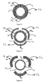
- the lateral thermal insulation system 6 is then constituted by at least two sub-elements 7a, 7b ( figure 1 ).
- the lateral thermal insulation element is cut along at least a first secant cutting plane at the bottom of the crucible 2.
- the main thermal insulation side element 7 is constituted by three sub-elements 7a, 7b and 7c which form a ring which surrounds the crucible 2.
- This ring is continuous when the thermal insulation side element is in a position isolation, that is to say that all the sub-elements are joined. In a position favoring thermal leaks, the sub-elements are no longer joined and the ring is discontinuous.
- the lateral element of additional thermal insulation 7 ' is constituted by three sub-elements 7'a, 7'b, 7'c on the Figures 4 to 6 .
- the lateral thermal insulation elements 7 and 7 ' can be cut according to different secant cutting planes at the bottom of the crucible 2.
- Each sub-element 7a, 7b, 7c, 7'a, 7b, 7'c comprises two main surfaces and four secondary surfaces.
- the main surface disposed opposite the outer surface of the side wall of the crucible is called the inner surface of the sub-element.
- the main surface facing outwards is called the outer surface of the sub-element.
- the inner surface of a sub-element is complementary to the outer surface of the sub-element or the crucible opposite.
- the inner surface of the sub-elements 7a is substantially complementary to the outer surface facing the crucible, so that they can fit one on the other.
- the lateral thermal insulation elements 6 and 7 can thus surround the side walls 5 of the crucible 2 in order to have maximum thermal insulation.
- the internal and external surfaces facing the lateral elements of the main and additional thermal insulation 7 '7' are complementary so that they can fit one on the other.
- the modulation means may comprise means for moving the lateral insulation elements 7 and 7 'in lateral directions A.
- Each lateral insulation element 7 and 7' being composed of a plurality of sub-elements, these sub-elements elements move in a lateral direction, which is their own and predefined, Aa, Ab, Ac on the figure 4 .
- This lateral direction of displacement can then be radial or tangential.
- a displacement tangential to the lateral surfaces that is to say a displacement along a tangent to a radius of a cylindrical crucible or parallel to a side face of a crucible with a square or rectangular base. It is also possible to have a radial displacement
- This lateral direction of displacement is perpendicular to the longitudinal direction L of the crucible 2 and passes through a characteristic point of each elementary insulator (7a-7c, 7'a-7'c).
- the lateral displacement direction A may be a vector orthogonal to the planar internal surface of the sub-element. In the case of the parallelepiped, the lateral direction of displacement can still be the direction which ensures the obtaining of an identical spacing between the differences faces of the sub-element and the lateral walls opposite the crucible 2.
- the cutting planes of the lateral thermal insulation elements 7 and 7 ' are advantageously identical, but they can also be shifted. It is also conceivable that the lateral thermal insulation elements 7 and 7 'do not have the same number of sub-elements. Since the lateral insulation elements 7 and 7 'can be divided into different section planes, a sub-element of the main thermal insulation side element 7 can cover, for example, two sub-elements of the lateral element of additional thermal insulation 7 '. They are not therefore obliged to have the same directions of movement, unlike the special case illustrated in Figures 4 to 6 .
- the internal surface of the lateral thermal insulation system 6 or of the main thermal insulation side element 7 is slightly larger than the external surface of the crucible 2 so that in a insulation position, a thin film of air or predetermined gas is present between the crucible 2 and the lateral insulation element 6 or 7, therefore between the crucible 2 and each of the sub-elements. It may be the same between the lateral elements 7 and additional thermal insulation 7 'so that in an insulation position, a thin film of air or predetermined gas is present between these two elements 7 and 7'.
- the sub-elements 7, 7 'of the lateral thermal insulation system 6 advantageously have the shape of a circular arc of a predefined thickness. If the crucible 2 is square-based or rectangular-based, the inner surface of the sub-elements may be a flat surface. However, if the sub-element is facing a stop of the crucible 2, its inner surface is said to be complex and comprises an angle between two plane surfaces ( figure 1 ).
- the lateral thermal insulation system 6 moves between an insulation position and a position promoting thermal leakage by the side walls 5. Typically, the lateral thermal insulation system 6 moves towards or away from the side walls 5 or the bottom 4 of the crucible 2.
- the distance between the crucible 2 and the thermal insulation side system 6 is the lowest allowed, which results in a minimum distance of the main and additional lateral elements 7 '7' relative to the walls 5. This minimum distance may be zero or equal to a predetermined thickness. In its position favoring thermal leaks, the distance between the crucible 2 and the lateral thermal insulation system 6 is the largest permitted and thermal leakage from the side walls 5 are the most important.
- the thermal leakage from the side walls of the crucible can be very small or greater, the proportion of leakage by the side walls can evolve continuously or discontinuously.
- the leaks are reduced to a minimum, which makes it possible to simultaneously have effective heating and stirring with the induction heating means while maintaining a good energy efficiency of this operation.
- thermal leakage from the sidewalls is greater and can increase continuously or discretely as crystallization occurs to accommodate a change in the thermal conductance of the material in the crucible. .
- the modulation means comprises means for moving the lateral insulation system 6, for example lateral insulation elements 7 and 7 ', in rotation around the longitudinal axis of the crucible. 2.
- the lateral insulation system 6 or elements 7 and 7 'independently of one another it is avoided to form cold areas on the crucible which are particularly detrimental.
- the elements 7 and 7 ' can move independently of one another, one of them can be fixed relative to the other or they can move at different speeds or in opposite directions.
- the longitudinal position of the lateral thermal insulation element 6 with respect to the bottom 4 of the crucible 2 makes it possible to create a more or less significant axial thermal gradient over the height of the crucible 2.
- the lateral thermal insulation system 6 can be movable in a longitudinal direction and in a lateral direction.
- This embodiment can obviously be applied to the main thermal insulation 7 and additional side elements 7 '.
- the lateral insulation elements 7 and 7 ' can thus move both in the longitudinal and lateral directions. It is also conceivable that the lateral main thermal insulating element 7 moves in a longitudinal direction and that the additional thermal insulation side element 7 'moves in a lateral direction.
- the insulating material constituting the lateral thermal insulation system 6 is advantageously made from an electrically insulating material so as to limit as much as possible the electromagnetic coupling generated by the furnace heating means.
- the insulating material has an electrical conductivity of less than 1 S / m.
- the insulating material is also chosen from materials having a low thermal conductivity, typically less than 15 W / m / K.
- the insulating material of the lateral thermal insulation system 6 can be chosen, for example, from alumina, Macor TM , mullite or zirconia.
- all the elements and lateral sub-elements of thermal insulation are made of the same material.
- the insulating material has an emissivity coefficient of between 0.3 and 0.6. Indeed, if the emissivity is low, the thermal insulating nature of the lateral thermal insulation and the additional lateral thermal insulation is reinforced, but the inertia of the furnace increases.
- the oven can operate under vacuum or under a controlled gaseous atmosphere.
- This gaseous atmosphere can be achieved by a gas selected from argon, oxygen, hydrogen, helium, nitrogen or air or a mixture based on these gases.
- the atmosphere consists of a neutral gas or a mixture of neutral gases.
- the heat losses by the side walls 5 are made by radiation and convection if the furnace 1 comprises a gaseous atmosphere.
- the thickness of the lateral thermal insulation system 6 and / or the elements 7 and 7 ' is constant or may have a continuous evolution.
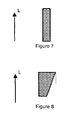
- the section of the lateral thermal insulation element 7 and 7 'in a sectional plane perpendicular to the bottom of the crucible has the shape of a rectangle or a rectangular trapezium. If the thickness is not constant over the entire height of the lateral insulation element 6, 7, 7 ', the largest thickness is advantageously located in the upper part of the thermal insulation. This variation in thickness also makes it possible to create a greater or lesser axial thermal gradient over the height of the crucible 2.
- the lateral thermal insulation and / or the additional lateral thermal insulation is pierced by a plurality of holes so that to modulate the thermal leak. It may then be advantageous to control the rotation or the offset angle between the lateral insulation elements 7 and 7 'in order to completely / partially obstruct the holes of the main lateral thermal element 7 by the additional lateral thermal element. 7 '. This mode of operation is particularly advantageous in the case of a cylindrical crucible.
- the modulation means may comprise means for moving the lateral insulation system 6, for example lateral insulation elements 7 and 7 ', in rotation around the longitudinal axis of the crucible 2.
- the thickness of the lateral thermal insulation system 6 or the sum of the thicknesses of the elements 7 and 7 ' is between 2 and 20 mm, more advantageously between 5 and 10 mm.
- the height of the lateral thermal insulation system 6 is between 10 and 20 cm.
- the displacement in the lateral direction between the lateral thermal insulation system 6 and the crucible may be between 0 and 10cm.
- the longitudinal displacement of the lateral thermal insulation system 6 is between 5 and 15 cm.
- a crystallization oven is a silicon-adapted furnace which can be produced in the following manner.
- the means for modulating the lateral heat losses comprise a main thermal insulation side element and an additional thermal insulation side element. These two lateral thermal insulation elements are made of alumina.
- the crucible is of cylindrical type, like that of the figure 3 .
- the diameter of the crucible is equal to 20 cm and the side walls have a height equal to 25 cm.
- the lateral thermal insulation elements have a height equal to 15 cm and a thickness equal to 8 mm.
- the oven also comprises a fixed insulating material whose thickness is equal to 5 cm. In operation, the temperature of the internal face of the insulator is of the order of 800 ° C.
- the thermal insulation side members are in an isolation position. They are joined to the crucible in order to minimize thermal losses from the side walls of the crucible. This isolation position is illustrated in the figure 2 or 4 .
- the heat flow extracted from the crucible by the side walls is then of the order of 10kW.
- the additional thermal insulation side member moves longitudinally continuously at a rate that is related to the rate of solidification of silicon from the bottom of the crucible.
- the direction of solidification of the silicon is identical to the direction of displacement of the lateral element of additional thermal insulation.
- the solidification rate is of the order of 10 mm / h.
- the lateral element of additional thermal insulation has moved longitudinally 10cm and this configuration is illustrated at the figure 3 or 6 .
- the heat flux extracted by the side walls is of the order of 13kW, which represents a 30% increase of the extracted flow with respect to the insulation configuration.
- the increase of the extracted flow with respect to the insulation configuration is of the order of 75%.
- the oven comprises cooling means which are arranged under the bottom of the crucible in order to impose a vertical thermal gradient.
Landscapes
- Chemical & Material Sciences (AREA)
- Engineering & Computer Science (AREA)
- Crystallography & Structural Chemistry (AREA)
- Materials Engineering (AREA)
- Metallurgy (AREA)
- Organic Chemistry (AREA)
- Physics & Mathematics (AREA)
- Thermal Sciences (AREA)
- Crystals, And After-Treatments Of Crystals (AREA)
- Silicon Compounds (AREA)
- Crucibles And Fluidized-Bed Furnaces (AREA)
Description
- L'invention est relative à un four de fusion et de solidification pour matériau cristallin comportant :
- un creuset ayant un fond et des parois latérales,
- un système latéral d'isolation thermique disposé à la périphérie du creuset autour des parois latérales,
- des moyens de déplacement d'au moins un élément latéral du système latéral d'isolation thermique, par rapport aux parois latérales, entre une position d'isolation et une position favorisant les fuites thermiques.
- De manière conventionnelle, les matériaux cristallins, typiquement les matériaux semi-conducteurs et les matériaux métalliques ne peuvent être utilisés tels quels dans les différents domaines technologiques à cause d'une pureté insuffisante et/ou d'une structure cristalline mal adaptée. Afin que les matériaux cristallins soient conformes à un cahier des charges très strict, ils sont soumis à différents cycles de fusion-solidification afin, par exemple, de réduire la teneur en impuretés dans le matériau et/ou imposer une organisation cristalline dans le matériau solide final.
- La purification du matériau cristallin peut être réalisée une première fois lors de la phase de fusion, en utilisant un procédé de purification de la phase liquide, par exemple, avec une torche à plasma. La purification peut également être réalisée lors de la solidification car les impuretés ségrégent préférentiellement depuis la phase solide vers le matériau fondu. De manière conventionnelle, la phase de solidification est utilisée pour définir la phase cristalline du matériau cristallin.
- De manière classique, le matériau à cristallisé est disposé, sous la forme d'une charge, dans un creuset qui est lui-même disposé dans un four vertical. Le four comporte des moyens de chauffage pour faire fondre le matériau cristallin ainsi que des moyens de refroidissement pour imposer un gradient thermique bien particulier au matériau fondu lors de sa phase de refroidissement. Les moyens de chauffage sont par exemple choisis de type inductif car ils permettent simultanément de chauffer le matériau cristallin tout en réalisant le brassage du matériau fondu.
- Cependant, lors des différentes phases du traitement du matériau à cristalliser, les fonctionnalités du four de traitement et de ses éléments constitutifs sont différentes. Tout d'abord, lors de la fusion du matériau, une très bonne isolation du four et surtout du creuset est nécessaire afin de réduire les pertes thermiques et assurer ainsi un rendement suffisant du four.
- Dans le cas de la purification, le contrôle de la température du four est important tout comme l'obtention d'un brassage efficace. Il est donc important de maîtriser la quantité d'énergie fournie au creuset, par rapport à celle qui est perdue par le creuset pour contrôler la température du matériau fondu. Par ailleurs, un bon brassage assure un renouvellement de la surface libre en polluants. Comme précisé plus haut, les moyens de chauffage inductif réalisent simultanément le chauffage et le brassage du bain liquide. Plus le courant circulant dans les bobines est important et plus le brassage et le chauffage sont importants, il est alors très difficile de maîtriser de façon précise un contrôle strict de la température du four tout en maintenant un brassage élevé, ces deux conditions étant contradictoires.
- Dans le cas de la solidification dirigée, l'extraction de la chaleur du matériau doit être parfaitement contrôlée, car c'est le gradient thermique appliqué au creuset qui conditionne l'avancée du front de solidification et ainsi la qualité cristallographique du matériau final. De plus, lors de la cristallisation, la phase liquide est également brassée pour assurer une répartition homogène des éléments constituants du matériau.
- Le document
WO 2005/105670 décrit une installation de fabrication de blocs en matériau semi-conducteur. Cette installation comporte deux enceintes distinctes et dédiées à des opérations spécifiques. Une première enceinte et un premier creuset sont utilisés pour réaliser la fusion et la purification du matériau semi-conducteur. Une seconde enceinte et un second creuset sont ensuite utilisés pour réaliser la cristallisation. Cette installation est complexe, elle nécessite des moyens de transvasement du matériau fondu du premier creuset dans le second creuset. Cette installation occupe une surface importante car il faut installer et gérer deux enceintes. - Le document
FR 2553232 - Le document
JP 05024964 US 2007/0227189 décrit un dispositif de cristallisation dans lequel des éléments plus thermiquement conducteurs se déplacent pour entrer en contact avec la paroi latérale d'un creuset. - L'invention a pour objet un four de fusion-cristallisation qui soit facile à mettre en oeuvre, qui n'utilise qu'un seul creuset pour la fusion et la cristallisation et qui permette de contrôler la surchauffe du matériau fondu tout en ayant un brassage important.
- Le four selon l'invention est caractérisé par les revendications annexées et plus particulièrement par le fait que :
- le système latéral d'isolation thermique est constitué par au moins deux sous-éléments adjacents formant un anneau continu dans la position d'isolation et discontinu dans la position favorisant les fuites thermiques et en ce qu'il comporte des moyens de déplacement dudit au moins un élément latéral suivant une direction latérale perpendiculaire à une direction longitudinale.
- D'autres avantages et caractéristiques ressortiront plus clairement de la description qui va suivre de modes particuliers de réalisation de l'invention donnés à titre d'exemples non limitatifs et représentés par les dessins annexés, dans lesquels :
- la
figure 1 représente, de manière schématique, en vue de dessus, un mode de réalisation particulier d'un creuset et d'un élément latéral d'isolation thermique, selon l'invention, - les
figures 2 et 3 représentent, de manière schématique, en section longitudinale, un autre mode de réalisation particulier d'un creuset et d'éléments latéraux d'isolation thermique, selon l'invention, dans deux configurations d'isolation différentes, - les
figures 4 à 6 représentent, de manière schématique, en vue de dessus, un troisième mode de réalisation particulier d'un creuset et d'éléments latéraux d'isolation thermique, selon l'invention, dans différentes configurations d'isolation, - les
figures 7 et 8 représentent, de manière schématique, des sections longitudinales d'un élément latéral d'isolation thermique selon l'invention. - Comme illustré aux
figures 1 à 6 , le four 1 de fusion-solidification comporte un creuset 2 dans lequel se trouve un matériau cristallin 3 de type semi-conducteur ou métallique. Le four 1 comporte également des moyens de chauffage par induction électromagnétique (non représentées) du matériau cristallin 3. Les moyens de chauffage sont réalisés, par exemple, par une ou plusieurs bobines à l'intérieur desquelles circule un courant alternatif de fréquence prédéfinie. - Le creuset 2 a un fond 4 et des parois latérales 5 en matériau réfractaire non refroidi, le creuset est donc de type creuset chaud. Les parois latérales 5 sont orientées suivant une direction longitudinale L qui est perpendiculaire au fond 4 du creuset 2. Les parois 5 ont une hauteur h depuis le fond 4 du creuset 2 dans la direction longitudinale L. Le creuset 2 présente une surface externe qui correspond à la surface extérieure de ses parois latérales 5. Le creuset 2 est associé à des moyens de modulation des fuites thermiques latérales. Ces moyens de modulation permettent de faire évoluer la proportion d'énergie thermique qui quitte le creuset 2 par ses parois latérales 5. Il y a alors un flux modulable d'énergie qui quitte le creuset en passant au travers de la surface externe du creuset 2.
- Pour cela, le four 1 comporte un système latéral d'isolation thermique 6, de forme annulaire, qui est disposé en périphérie du creuset 2 autour des parois latérales 5. Le système latéral d'isolation thermique 6 est mobile par rapport au creuset 2. Avantageusement, au moins les parois latérales 5 du creuset 2 sont recouvertes par un matériau isolant supplémentaire (non représenté) qui est fixe par rapport au creuset 2 et qui réalise une première isolation thermique du creuset 2. Le système latéral d'isolation thermique 6 comporte au moins un élément latéral d'isolation thermique 7 qui se déplace par rapport au creuset 2.
- Dans une variante de réalisation, le système latéral d'isolation thermique 6 comporte un élément latéral d'isolation thermique principal 7 et un élément latéral d'isolation thermique additionnel 7' (
figures 2 à 6 ). L'élément latéral d'isolation thermique principal 7 est alors entouré par l'élément latéral d'isolation thermique additionnel 7' distinct. Ces deux éléments latéraux d'isolation thermique 7 et 7' sont mobiles et peuvent se déplacer indépendamment l'un de l'autre. - Si le système latéral d'isolation thermique 6 ne comporte qu'un seul élément latéral d'isolation thermique, l'élément latéral d'isolation thermique 7, ce dernier peut être assimilé au système 6 et il peut être noté comme l'élément latéral d'isolation thermique 6.
- Les moyens de modulation des fuites thermiques latérales comportent des moyens de déplacement du système latéral d'isolation thermique 6 par rapport aux parois latérales du creuset 2. Les moyens de déplacement peuvent également comporter, suivant les modes de réalisation, des moyens de déplacement indépendant des éléments latéraux d'isolation thermique principal 7 et additionnel 7'. Le système latéral d'isolation thermique 6 se déplace alors entre une position d'isolation et une position qui favorise les fuites thermiques par les parois latérales 5.
- Les moyens de déplacement peuvent comporter des moyens de déplacement d'au moins un élément latéral d'isolation thermique 7, 7' suivant la direction longitudinale L. Ce mode de réalisation est avantageux si l'élément latéral d'isolation thermique 7, 7' a une hauteur égale à celle du creuset 2. Avantageusement, dans la position d'isolation, toute la hauteur de l'élément latéral d'isolation thermique 7, 7' est en regard des parois latérales afin de réduire au maximum les pertes.
- Comme illustré aux
figures 2 et 3 , les moyens de modulation comportent des moyens de déplacement des éléments latéraux d'isolation thermique principal 7 et additionnel 7' suivant la direction longitudinale L. Dans ce cas de figure, les éléments latéraux d'isolation 7 et 7' se déplacent par rapport au fond 4 du creuset 2 et leur écartement par rapport aux parois latérales 5 est constant. - Ce mode de réalisation est avantageux si les éléments latéraux d'isolation 7 et 7' ont une hauteur inférieure à celle du creuset 2 et particulièrement inférieure à celle de la quantité de matière fondue dans le creuset 2. Dans une position d'isolation dite verticale, les éléments latéraux d'isolation 7 et 7' recouvrent la totalité de la hauteur des parois latérales 5 tout en ayant, entre eux, le maximum de surface en regard. Afin d'augmenter les pertes thermiques par les parois latérales 5, la couverture de l'intégralité de la hauteur des parois latérales 5 n'est plus assurée. Les éléments latéraux d'isolation 7 et 7' se rapprochent l'un de l'autre par un déplacement longitudinal. C'est l'élément latéral d'isolation 7 ou 7' qui recouvre la partie inférieure des parois latérales 5 qui se déplace longitudinalement vers la partie supérieure des parois latérales 5.
- Dans un autre mode de réalisation qui peut être combiné au précédent, les moyens de déplacement peuvent également comporter des moyens de déplacement de l'élément latéral d'isolation thermique 6 suivant une direction latérale. La direction latérale de déplacement est perpendiculaire à la direction longitudinale L. Dans ce cas de figure, le système latéral d'isolation thermique 6 comporte au moins un l'élément latéral d'isolation thermique qui est divisé obligatoirement en une pluralité de sous-éléments afin d'autoriser le rapprochement ou l'écartement de chacun des sous-éléments dans une direction qui lui est propre. En d'autres termes, les moyens de modulation des fuites thermiques latérales comportent des moyens de déplacement de chaque sous-élément indépendamment les uns des autres.
- Le système latéral d'isolation thermique 6 est alors constitué par au moins deux sous-éléments 7a, 7b (
figure 1 ). L'élément latéral d'isolation thermique est découpé suivant au moins un premier plan de coupe sécant au fond du creuset 2. - Comme illustré aux
figures 4 à 6 , l'élément latéral d'isolation thermique principal 7 est constitué par trois sous-éléments 7a, 7b et 7c qui forment un anneau qui entoure le creuset 2. Cet anneau est continu lorsque l'élément latéral d'isolation thermique est dans une position d'isolation, c'est-à-dire que tous les sous-éléments sont jointifs. Dans une position favorisant les fuites thermiques, les sous-éléments ne sont plus jointifs et l'anneau est discontinu. - Il en va de même du système latéral d'isolation thermique 6 qui entoure le creuset rectangulaire de la
figure 1 . - De manière analogue, l'élément latéral d'isolation thermique additionnel 7' est constitué par trois sous-éléments 7'a, 7'b, 7'c sur les
figures 4 à 6 . Les éléments latéraux d'isolation thermique 7 et 7' peuvent être découpés suivant des plans de coupe différents sécants au fond du creuset 2. - Chaque sous-élément 7a, 7b, 7c, 7'a, 7b, 7'c comporte deux surfaces principales et quatre surfaces secondaires. La surface principale disposée en regard de la surface externe de la paroi latérale du creuset est appelée surface interne du sous-élément La surface principale dirigée vers l'extérieur est appelée surface externe du sous-élément. La surface interne d'un sous-élément est complémentaire de la surface externe du sous-élément ou du creuset en regard. Ainsi, à titre d'exemple, la surface interne des sous-éléments 7a est sensiblement complémentaire de la surface externe en regard du creuset, de sorte qu'elles peuvent s'emboîter l'une sur l'autre. Les éléments latéraux d'isolation thermique 6 et 7 peuvent donc entourer les parois latérales 5 du creuset 2 afin d'avoir une isolation thermique maximale.
- De la même manière, les surfaces internes et externes en regard des éléments latéraux d'isolation thermique principal 7 et additionnel 7' sont complémentaires de sorte qu'elles peuvent s'emboîter l'une sur l'autre. L'élément latéral d'isolation thermique additionnel 7' peut donc entourer les parois latérales de l'élément latéral d'isolation thermique principal 7 afin d'avoir une isolation thermique maximale dans sa position d'isolation.
- Comme illustré aux
figures 3 à 6 , les moyens de modulation peuvent comporter des moyens de déplacement des éléments latéraux d'isolation 7 et 7' suivant des directions latérales A. Chaque élément latéral d'isolation 7 et 7' étant composé par une pluralité de sous-éléments, ces sous-éléments se déplacent suivant une direction latérale, qui leur est propre et prédéfinie, Aa, Ab, Ac sur lafigure 4 . Cette direction latérale de déplacement peut alors être radiale ou tangentielle. Ainsi, il est envisageable d'avoir un déplacement tangentiel par rapport aux surfaces latérales, c'est-à-dire un déplacement selon une tangente à un rayon d'un creuset cylindrique ou parallèlement à une face latérale d'un creuset à base carrée ou rectangulaire. Il est également envisageable d'avoir un déplacement radial - Cette direction latérale de déplacement est perpendiculaire à la direction longitudinale L du creuset 2 et passe par un point caractéristique de chaque isolant élémentaire (7a-7c, 7'a-7'c). La direction latérale de déplacement A peut être un vecteur orthogonal à la surface interne plane du sous-élément. Dans le cas du parallélépipède, la direction latérale de déplacement peut être encore la direction qui assure l'obtention d'un écartement identique entre les différences faces du sous-élément et les parois latérales en regard du creuset 2.
- Les plans de coupe des éléments latéraux d'isolation thermique 7 et 7' sont avantageusement identiques, mais ils peuvent également être décalés. Il est également envisageable que les éléments latéraux d'isolation thermique 7 et 7' n'aient pas le même nombre de sous-éléments. Les éléments latéraux d'isolation 7 et 7' pouvant être divisés selon des plans de coupe différents, un sous-élément de l'élément latéral d'isolation thermique principal 7 peut recouvrir par exemple, deux sous-éléments de l'élément latéral d'isolation thermique additionnel 7'. Ils ne sont donc pas obligés de posséder les mêmes directions de déplacement, contrairement au cas particulier illustré aux
figures 4 à 6 . - Dans un mode de réalisation particulier combinable avec les précédents, la surface interne du système latéral d'isolation thermique 6 ou de l'élément latéral d'isolation thermique principal 7 est légèrement plus grande que la surface externe du creuset 2 de sorte que dans une position d'isolation, une fine pellicule d'air ou de gaz prédéterminé est présente entre le creuset 2 et l'élément latéral d'isolation 6 ou 7, donc entre le creuset 2 et chacun des sous-éléments. Il peut en être de même entre les éléments latéraux d'isolation thermique principal 7 et additionnel 7' afin que dans une position d'isolation, une fine pellicule d'air ou de gaz prédéterminé soit présente entre ces deux éléments 7 et 7'.
- Si, le creuset 2 est de forme cylindrique, les sous-éléments 7, 7' du système latéral d'isolation thermique 6 ont avantageusement la forme d'un arc de cercle d'une épaisseur prédéfinie. Si le creuset 2 est à base carrée ou à base rectangulaire, la surface interne des sous-éléments peut être une surface plane. Cependant, si le sous-élément est en regard d'une arrête du creuset 2, sa surface interne est dite complexe et comporte un angle entre deux surfaces planes (
figure 1 ). - Afin d'être utilisable lors d'une phase de fusion, de purification et de solidification, le système latéral d'isolation thermique 6 se déplace entre une position d'isolation et une position favorisant les fuites thermiques par les parois latérales 5. Typiquement, le système latéral d'isolation thermique 6 se rapproche ou s'éloigne des parois latérales 5 ou du fond 4 du creuset 2.
- Comme illustré aux
figures 3 à 6 , dans sa position d'isolation, la distance entre le creuset 2 et le système latéral d'isolation thermique 6 est la plus faible autorisée, ce qui se traduit par une distance minimale des éléments latéraux principal 7 et additionnel 7' par rapport au parois latérales 5. Cette distance minimale peut être nulle ou égale à une épaisseur prédéterminée. Dans sa position favorisant les fuites thermiques, la distance entre le creuset 2 et le système latéral d'isolation thermique 6 est la plus grande autorisée et les fuites thermiques par les parois latérales 5 sont les plus importantes. - De cette manière, selon la configuration prise par les moyens de modulation, les fuites thermiques par les parois latérales du creuset peuvent être très réduites ou alors plus importantes, la proportion de fuite par les parois latérales pouvant évoluée de façon continue ou discontinue.
- Lors de la phase de fusion, les fuites sont réduites au minimum ce qui permet d'avoir simultanément un chauffage et un brassage efficaces avec les moyens de chauffage par induction tout en conservant un bon rendement énergétique de cette opération. Lors de la cristallisation, les fuites thermiques par les parois latérales sont plus importantes et elles peuvent augmenter de manière continue ou de manière discrète au fur et à mesure de la cristallisation pour s'adapter à une modification de la conductance thermique du matériau dans le creuset.
- Dans ce mode de réalisation, il est avantageux que les moyens de modulation comportent des moyens de déplacement du système latéral d'isolation 6, par exemple des éléments latéraux d'isolation 7 et 7', en rotation autour de l'axe longitudinal du creuset 2. En réalisant la rotation du système latérale 6 ou des éléments 7 et 7' indépendamment l'un de l'autre, on évite de former des zones froides sur le creuset qui sont particulièrement préjudiciables. Les éléments 7 et 7' peuvent se déplacer indépendamment l'un de l'autre, l'un des deux peut donc être fixe par rapport à l'autre ou ils peuvent se mouvoir à des vitesses différentes ou dans des sens opposés.
- La position longitudinale de l'élément latéral d'isolation thermique 6 par rapport au fond 4 du creuset 2 permet de créer un gradient thermique axial plus ou moins important sur la hauteur du creuset 2.
- Dans un autre mode de réalisation particulier qui correspond à la combinaison des différents modes de réalisation des
figures 1 à 6 , le système latéral d'isolation thermique 6 peut être mobile suivant une direction longitudinale et suivant une direction latérale. Ce mode de réalisation peut évidemment être appliqué aux éléments latéraux d'isolation thermique principal 7 et additionnel 7'. Les éléments latéraux d'isolation 7 et 7' peuvent donc se déplacer tous les deux dans les directions longitudinale et latérales. Il est également envisageable que l'élément latéral d'isolation thermique principal 7 se déplace suivant une direction longitudinale et que l'élément latéral d'isolation thermique additionnel 7' se déplace suivant une direction latérale. - Le matériau isolant constituant le système latéral d'isolation thermique 6 est avantageusement réalisé à partir d'un matériau électriquement isolant de manière à limiter le plus possible le couplage électromagnétique engendré par les moyens de chauffage du four. Le matériau isolant présente une conductivité électrique inférieure à 1 S/m. Le matériau isolant est également choisi parmi les matériaux présentant une conductivité thermique faible, typiquement inférieure à 15W/m/K.
- Le matériau isolant du système latéral d'isolation thermique 6 peut être choisi, par exemple, parmi l'alumine, le Macor™, la mullite ou la zircone. Avantageusement, tous les éléments et sous-éléments latéraux d'isolation thermique sont réalisés dans le même matériau.
- Avantageusement, le matériau isolant présente un coefficient d'émissivité compris entre 0,3 et 0,6. En effet, si l'émissivité est faible, le caractère isolant thermique de l'isolant thermique latéral et de l'isolant thermique latéral additionnel est renforcé, mais l'inertie du four augmente.
- Le four peut fonctionner sous vide ou sous une atmosphère gazeuse contrôlée. Cette atmosphère gazeuse peut être réalisée par un gaz choisi parmi l'argon, l'oxygène, l'hydrogène, l'hélium, l'azote ou l'air ou un mélange à base de ces gaz. Avantageusement, l'atmosphère est constituée par un gaz neutre ou un mélange de gaz neutres.
- Les pertes thermiques par les parois latérales 5 sont réalisées par rayonnement et par convection si le four 1 comporte une atmosphère gazeuse.
- Suivant la direction longitudinale, l'épaisseur du système latéral d'isolation thermique 6 et/ou des éléments 7 et 7' est constante ou peut présenter une évolution continue. La section de l'élément latéral d'isolation thermique 7 et 7' dans un plan de coupe perpendiculaire au fond du creuset a la forme d'un rectangle ou d'un trapèze rectangle. Si l'épaisseur n'est pas constante sur toute la hauteur de l'élément latéral d'isolation 6, 7, 7', l'épaisseur la plus importante se situe avantageusement dans la partie supérieure de l'isolant thermique. Cette variation d'épaisseur permet également de créer un gradient thermique axial plus ou moins important sur la hauteur du creuset 2.
- Dans un mode de réalisation particulier, l'isolant thermique latéral et/ou de l'isolant thermique latéral additionnel est percé par une pluralité de trous afin de moduler la fuite thermique. Il peut être alors avantageux de contrôler la rotation ou l'angle de décalage entre les élément latéraux d'isolation 7 et 7' afin de venir obstruer complètement/partiellement les trous de l'élément thermique latéral principal 7 par l'élément thermique latéral additionnel 7'. Ce mode de fonctionnement est particulièrement avantageux dans le cas d'un creuset cylindrique.
- Dans ce mode de réalisation, les moyens de modulation peuvent comporter des moyens de déplacement du système latéral d'isolation 6, par exemple des éléments latéraux d'isolation 7 et 7', en rotation autour de l'axe longitudinal du creuset 2.
- Avantageusement, l'épaisseur du système latéral d'isolation thermique 6 ou la somme des épaisseurs des éléments 7 et 7' est comprise entre 2 et 20mm, encore plus avantageusement entre 5 et 10mm. Typiquement, la hauteur de le système latéral d'isolation thermique 6 est comprise entre 10 et 20 cm.
- A titre d'exemple, le déplacement suivant la direction latérale entre le système latéral d'isolation thermique 6 et le creuset peut être comprise entre 0 et 10cm.
- A titre d'exemple également, le déplacement longitudinal du système latéral d'isolation thermique 6 est compris entre 5 et 15cm.
- Le flux de chaleur extrait du creuset 2 est modulé par la variation de la configuration géométrique du creuset 2 par rapport à l'élément latéral d'isolation thermique 6 et éventuellement aux éléments 7 et 7'. La modulation du flux thermique peut être réalisée en modulant uniquement ou en combinaison :
- l'écartement, dans une direction latérale, entre le système latéral d'isolation thermique 6 et les parois latérales 5,
- l'écartement, dans une direction latérale, entre l'élément latéral d'isolation thermique principal 7 et l'élément latéral d'isolation thermique additionnel 7 ainsi que leur écartement par rapport au creuset,
- le recouvrement, dans une direction verticale, de l'élément latéral d'isolation thermique 6, ou des éléments 7 et 7', avec les parois latérales 5 du creuset 2,
- le recouvrement, dans une direction verticale, des éléments 7 et 7' entre eux,
- la composition de l'atmosphère gazeuse au sein du four 1,
- le recouvrement par rotation angulaire.
- A titre d'exemple, un four de cristallogenèse selon l'invention est un four adapté au silicium qui peut être réalisé de la manière qui suit. Les moyens de modulation des pertes thermiques latérales comportent un élément latéral d'isolation thermique principal et un élément latéral d'isolation thermique additionnel. Ces deux éléments latéraux d'isolation thermique sont réalisés en alumine. Le creuset est de type cylindrique, comme celui de la
figure 3 . Le diamètre du creuset est égal à 20cm et les parois latérales ont une hauteur égale à 25cm. Les éléments latéraux d'isolation thermique ont une hauteur égale à 15cm et une épaisseur égale à 8mm. Le four comporte également un matériau isolant fixe dont l'épaisseur est égale à 5 cm. En fonctionnement, la température de la face interne de l'isolant est de l'ordre de 800°C. - Pendant la phase de fusion, les éléments latéraux d'isolation thermique sont dans une position d'isolation. Ils sont jointifs du creuset afin de réduire au maximum les pertes thermiques depuis les parois latérales du creuset. Cette position d'isolation est illustrée à la
figure 2 ou4 . Le flux de chaleur extrait du creuset par les parois latérales est alors de l'ordre de 10kW. Une fois que la solidification est initiée, l'élément latéral d'isolation thermique additionnel se déplace longitudinalement de manière continue suivant une vitesse qui est reliée à la vitesse de solidification du silicium depuis le fond du creuset. La direction de solidification du silicium est identique à la direction de déplacement de l'élément latéral d'isolation thermique additionnel. La vitesse de solidification est de l'ordre de 10mm/h. - A la fin de la solidification, lorsqu'il ne reste presque plus de matériau fondu, l'élément latéral d'isolation thermique additionnel s'est déplacé longitudinalement de 10cm et cette configuration est illustrée à la
figure 3 ou6 . Le flux de chaleur extrait par les parois latérales est de l'ordre de 13kW, ce qui représente une augmentation de 30% du flux extrait par rapport à la configuration d'isolation. - Dans le cas où les deux éléments latéraux d'isolation thermique ne sont plus réalisés en alumine mais en Macor™, l'augmentation du flux extrait par rapport à la configuration d'isolation est de l'ordre de 75%.
- Le four comporte des moyens de refroidissement qui sont disposés sous le fond du creuset afin d'imposer un gradient thermique vertical.
Claims (11)
- Four (1) de fusion et de solidification pour matériau cristallin (3) comportant :- un creuset (2) ayant un fond (4) et des parois latérales (5), le creuset présentant une direction longitudinale perpendiculaire au fond (4)- un système latéral d'isolation thermique (6) disposé autour du creuset (2) face aux parois latérales (5), le système latéral d'isolation thermique (6) comportant au moins un élément latéral (7a, 7b, 7c, 7'a, 7'b, 7'c) se déplaçant entre une position d'isolation et une position favorisant les fuites thermiques,four caractérisé en ce que :- le système latéral d'isolation thermique (6) est constitué par au moins deux sous-éléments adjacents formant un anneau continu dans la position d'isolation et discontinu dans la position favorisant les fuites thermiques et en ce qu'il comporte des moyens de déplacement dudit au moins un élément latéral (7a, 7b, 7c, 7'a, 7'b, 7'c) suivant une direction latérale perpendiculaire à la direction longitudinale.
- Four selon la revendication 1, caractérisé en ce que le système latéral d'isolation thermique (6) comporte au moins des éléments latéraux d'isolation principal (7a, 7b, 7c) et additionnel (7'a, 7'b, 7'c).
- Four selon l'une des revendications 1 et 2, caractérisé en ce que les moyens de déplacement comportent des moyens de déplacement d'au moins un élément latéral (7a, 7b, 7c, 7'a, 7'b, 7'c) du système latéral d'isolation thermique (6), suivant une direction longitudinale.
- Four selon l'une quelconque des revendications 1 à 3, caractérisé en ce que les moyens de déplacement comportant des moyens de déplacement d'au moins un élément latéral (7a, 7b, 7c, 7'a, 7'b, 7'c) du système latéral d'isolation thermique (6) en rotation par rapport à l'axe longitudinal du creuset (2).
- Four selon l'une quelconque des revendications 1 à 4, caractérisé en ce qu'au moins un élément latéral d'isolation thermique (7a, 7b, 7c, 7'a, 7'b, 7'c) présente une émissivité comprise entre 0,3 et 0,6.
- Four selon l'une quelconque des revendications 1 à 5, caractérisé en ce que le système latéral d'isolation thermique (6) est réalisé dans un matériau choisi parmi l'alumine, le Macor™, la mullite ou la zircone.
- Four selon l'une quelconque des revendications 1 à 6, caractérisé en ce que le système latéral d'isolation thermique (6) a une hauteur identique à une hauteur des parois latérales (5).
- Four selon l'une quelconque des revendications 1 à 6, caractérisé en ce que le système latéral d'isolation thermique (6) a une hauteur inférieure à une hauteur des parois latérales (5).
- Four selon l'une quelconque des revendications 1 à 8, caractérisé en ce qu'au moins un élément latéral (7a, 7b, 7c, 7'a, 7'b, 7'c) du système latéral d'isolation thermique (6) a une section rectangulaire selon un plan perpendiculaire au fond (4) du creuset (2).
- Four selon l'une quelconque des revendications 1 à 8, caractérisé en ce qu'au moins un élément latéral (7a, 7b, 7c, 7'a, 7'b, 7'c) du système latéral d'isolation thermique (6) a une section trapézoïdale rectangle selon un plan perpendiculaire au fond (4) du creuset (2).
- Four selon l'une quelconque des revendications 1 à 10, caractérisé en ce qu'il comporte des moyens de chauffage du matériau cristalline par induction électromagnétique et en ce que le système latéral d'isolation thermique (6) a une conductivité électrique inférieure à 1S/m et une conductivité thermique inférieure à 15W/m/K.
Priority Applications (1)
| Application Number | Priority Date | Filing Date | Title |
|---|---|---|---|
| PL09763974T PL2376679T3 (pl) | 2008-12-19 | 2009-12-04 | Piec do topienia-krzepnięcia z modulowaną wymianą ciepła przez ściany boczne |
Applications Claiming Priority (2)
| Application Number | Priority Date | Filing Date | Title |
|---|---|---|---|
| FR0807241A FR2940327B1 (fr) | 2008-12-19 | 2008-12-19 | Four de fusion-solidification comportant une modulation des echanges thermiques par les parois laterales |
| PCT/EP2009/066393 WO2010069784A1 (fr) | 2008-12-19 | 2009-12-04 | Four de fusion-solidification comportant une modulation des échanges thermiques par les parois latérales |
Publications (2)
| Publication Number | Publication Date |
|---|---|
| EP2376679A1 EP2376679A1 (fr) | 2011-10-19 |
| EP2376679B1 true EP2376679B1 (fr) | 2013-03-27 |
Family
ID=41092050
Family Applications (1)
| Application Number | Title | Priority Date | Filing Date |
|---|---|---|---|
| EP09763974A Not-in-force EP2376679B1 (fr) | 2008-12-19 | 2009-12-04 | Four de fusion-solidification comportant une modulation des échanges thermiques par les parois latérales |
Country Status (13)
| Country | Link |
|---|---|
| US (1) | US9127373B2 (fr) |
| EP (1) | EP2376679B1 (fr) |
| JP (1) | JP2012512797A (fr) |
| KR (1) | KR101699987B1 (fr) |
| CN (1) | CN102257188B (fr) |
| BR (1) | BRPI0922977A2 (fr) |
| CA (1) | CA2743543C (fr) |
| EA (1) | EA019628B1 (fr) |
| ES (1) | ES2404825T3 (fr) |
| FR (1) | FR2940327B1 (fr) |
| PL (1) | PL2376679T3 (fr) |
| WO (1) | WO2010069784A1 (fr) |
| ZA (1) | ZA201103451B (fr) |
Families Citing this family (14)
| Publication number | Priority date | Publication date | Assignee | Title |
|---|---|---|---|---|
| US20120248286A1 (en) * | 2011-03-31 | 2012-10-04 | Memc Singapore Pte. Ltd. (Uen200614794D) | Systems For Insulating Directional Solidification Furnaces |
| CN102181655B (zh) * | 2011-04-11 | 2012-11-07 | 江西稀有金属钨业控股集团有限公司 | 一种钽材质多级蒸馏坩埚和蒸馏工艺 |
| TWI432617B (zh) * | 2011-07-12 | 2014-04-01 | Sino American Silicon Prod Inc | 長晶裝置 |
| US20130239620A1 (en) * | 2011-09-14 | 2013-09-19 | Memc Singapore, Pte. Ltd (Uen200614797D) | Directional Solidification Furnace Having Movable Insulation System |
| KR20140059803A (ko) | 2011-09-14 | 2014-05-16 | 엠이엠씨 싱가포르 피티이. 엘티디. | 이동식 열교환기를 구비한 방향성 응고로 |
| US9352389B2 (en) * | 2011-09-16 | 2016-05-31 | Silicor Materials, Inc. | Directional solidification system and method |
| FR2985722B1 (fr) * | 2012-01-13 | 2014-02-14 | Commissariat Energie Atomique | Procede de purification du silicium. |
| US9273411B2 (en) * | 2012-11-02 | 2016-03-01 | Gtat Corporation | Growth determination in the solidification of a crystalline material |
| TWI643983B (zh) | 2013-03-14 | 2018-12-11 | 美商希利柯爾材料股份有限公司 | 定向凝固系統及方法 |
| KR102319998B1 (ko) * | 2015-01-22 | 2021-11-01 | 삼성디스플레이 주식회사 | 볼륨 가변형 도가니를 구비한 증착원 |
| US20160281212A1 (en) | 2015-03-24 | 2016-09-29 | Siva Power, Inc. | Thermal management of evaporation sources |
| CN108534193A (zh) * | 2018-05-09 | 2018-09-14 | 浙江厨壹堂厨房电器股份有限公司 | 一种集成灶中的燃气接管 |
| JP7186534B2 (ja) | 2018-07-25 | 2022-12-09 | 昭和電工株式会社 | 結晶成長装置 |
| DE102020117661A1 (de) * | 2020-07-03 | 2022-01-20 | Friedrich-Alexander-Universität Erlangen-Nürnberg | Kristallzüchtungsanlage zur Herstellung eines Einkristalls |
Family Cites Families (12)
| Publication number | Priority date | Publication date | Assignee | Title |
|---|---|---|---|---|
| JPS59143039U (ja) | 1983-03-11 | 1984-09-25 | 富士通株式会社 | 加熱炉 |
| FR2553232B1 (fr) | 1983-10-05 | 1985-12-27 | Comp Generale Electricite | Procede et dispositif pour elaborer un lingot d'un materiau semi-conducteur polycristallin |
| JP2870795B2 (ja) | 1989-04-27 | 1999-03-17 | 東芝セラミックス株式会社 | 縦型熱処理炉 |
| JP2734820B2 (ja) * | 1991-07-16 | 1998-04-02 | 株式会社神戸製鋼所 | 化合物半導体単結晶の製造方法 |
| JPH07242487A (ja) * | 1994-03-01 | 1995-09-19 | Hitachi Cable Ltd | 化合物半導体単結晶製造装置 |
| FR2741633B1 (fr) | 1995-11-23 | 1997-12-19 | Commissariat Energie Atomique | Four de cristallisation pour materiau a faible conductivite thermique et/ou faible durete |
| JP4657465B2 (ja) | 2001-02-09 | 2011-03-23 | 古河機械金属株式会社 | 金属の精製方法 |
| JP2004010461A (ja) * | 2002-06-11 | 2004-01-15 | Canon Inc | 結晶製造装置および結晶製造方法 |
| DE60316337T2 (de) * | 2002-10-18 | 2008-06-05 | Evergreen Solar Inc., Marlborough | Verfahren und vorrichtung zur kristallzüchtung |
| WO2005092791A1 (fr) * | 2004-03-29 | 2005-10-06 | Kyocera Corporation | Dispositif de coulage de silicium et procede de fabrication de lingots de silicium multicristallin |
| FR2869028B1 (fr) | 2004-04-20 | 2006-07-07 | Efd Induction Sa Sa | Procede et installation de fabrication de blocs d'un materiau semiconducteur |
| US7344596B2 (en) * | 2005-08-25 | 2008-03-18 | Crystal Systems, Inc. | System and method for crystal growing |
-
2008
- 2008-12-19 FR FR0807241A patent/FR2940327B1/fr not_active Expired - Fee Related
-
2009
- 2009-12-04 BR BRPI0922977A patent/BRPI0922977A2/pt not_active Application Discontinuation
- 2009-12-04 CN CN200980150827.8A patent/CN102257188B/zh not_active Expired - Fee Related
- 2009-12-04 PL PL09763974T patent/PL2376679T3/pl unknown
- 2009-12-04 CA CA2743543A patent/CA2743543C/fr not_active Expired - Fee Related
- 2009-12-04 ES ES09763974T patent/ES2404825T3/es active Active
- 2009-12-04 KR KR1020117013795A patent/KR101699987B1/ko not_active Expired - Fee Related
- 2009-12-04 EA EA201170842A patent/EA019628B1/ru not_active IP Right Cessation
- 2009-12-04 JP JP2011541301A patent/JP2012512797A/ja active Pending
- 2009-12-04 EP EP09763974A patent/EP2376679B1/fr not_active Not-in-force
- 2009-12-04 US US13/130,188 patent/US9127373B2/en not_active Expired - Fee Related
- 2009-12-04 WO PCT/EP2009/066393 patent/WO2010069784A1/fr not_active Ceased
-
2011
- 2011-05-11 ZA ZA2011/03451A patent/ZA201103451B/en unknown
Also Published As
| Publication number | Publication date |
|---|---|
| EP2376679A1 (fr) | 2011-10-19 |
| KR20110106304A (ko) | 2011-09-28 |
| FR2940327A1 (fr) | 2010-06-25 |
| PL2376679T3 (pl) | 2013-08-30 |
| WO2010069784A1 (fr) | 2010-06-24 |
| CN102257188A (zh) | 2011-11-23 |
| ZA201103451B (en) | 2012-01-25 |
| CA2743543C (fr) | 2016-05-17 |
| KR101699987B1 (ko) | 2017-01-26 |
| JP2012512797A (ja) | 2012-06-07 |
| EA019628B1 (ru) | 2014-05-30 |
| EA201170842A1 (ru) | 2011-12-30 |
| FR2940327B1 (fr) | 2011-02-11 |
| ES2404825T3 (es) | 2013-05-29 |
| CA2743543A1 (fr) | 2010-06-24 |
| BRPI0922977A2 (pt) | 2016-01-26 |
| CN102257188B (zh) | 2014-07-30 |
| US9127373B2 (en) | 2015-09-08 |
| US20110259316A1 (en) | 2011-10-27 |
Similar Documents
| Publication | Publication Date | Title |
|---|---|---|
| EP2376679B1 (fr) | Four de fusion-solidification comportant une modulation des échanges thermiques par les parois latérales | |
| EP2014803B1 (fr) | Dispositif de fabrication d'un bloc de matériau cristallin avec modulation de la conductivité thermique | |
| EP2646604B1 (fr) | Echangeur thermique d'un systeme de solidification et/ou de cristallisation d'un materiau semi-conducteur | |
| EP1613795B2 (fr) | CREUSET POUR UN DISPOSITIF DE FABRICATION D’UN BLOC DE MATERIAU CRISTALLIN ET PROCEDE DE FABRICATION | |
| EP2014802A1 (fr) | Procédé d'élaboration de plaquettes en matériau semi-conducteur par moulage et cristillisation dirigée | |
| EP2751309A1 (fr) | Système de fabrication d'un matériau cristallin par cristallisation dirigée muni d'une source de chaleur additionnelle latérale | |
| EP0914751A1 (fr) | Four de fusion de verre par induction en creuset froid | |
| TWI568899B (zh) | 用於加熱供半導體材料之生長用之爐具的技術 | |
| FR2786208A1 (fr) | Procede de croissance cristalline sur substrat et reacteur pour sa mise en oeuvre | |
| FR2950046A1 (fr) | Dispositif a basse pression de fusion et purification de silicium et procede de fusion/purification/solidification | |
| CA2569755C (fr) | Installation d'affinage de silicium | |
| FR2979638A1 (fr) | Dispositif de fabrication de materiau cristallin a partir d'un creuset a resistance thermique non uniforme | |
| EP1969163B1 (fr) | Dispositif et procede de fabrication d'un bloc de materiau cristallin | |
| FR2695511A1 (fr) | Pile solaire en film mince, procédé pour sa production, procédé de production d'un lingot semi-conducteur et procédé de production d'un substrat semi-conducteur. | |
| EP0671116B1 (fr) | Dispositif pour la fusion electrique | |
| JP2016200254A (ja) | 断熱構造体 | |
| EP1399606B1 (fr) | Dispositif de fabrication de cristaux d'alliage | |
| WO2012127152A1 (fr) | Creuset de four a induction | |
| US8263914B2 (en) | Cartridge heater and method of use | |
| FR2628993A3 (fr) | Dispositif d'obturation laterale de l'espace de coulee d'une lingotiere de coulee continue entre cylindres | |
| JP2004071172A (ja) | 加熱装置およびその製造方法並びに被膜形成装置 | |
| FR2864416A1 (fr) | Thermo-plongeur electrique a element chauffant gaine | |
| FR3100421A1 (fr) | Four à induction comprenant un circuit résonant additionnel | |
| JP2006232591A (ja) | 鋳造装置及び多結晶シリコンインゴットの鋳造方法 | |
| JP2013116832A (ja) | シリコン精製装置およびシリコン精製方法 |
Legal Events
| Date | Code | Title | Description |
|---|---|---|---|
| PUAI | Public reference made under article 153(3) epc to a published international application that has entered the european phase |
Free format text: ORIGINAL CODE: 0009012 |
|
| 17P | Request for examination filed |
Effective date: 20110606 |
|
| AK | Designated contracting states |
Kind code of ref document: A1 Designated state(s): AT BE BG CH CY CZ DE DK EE ES FI FR GB GR HR HU IE IS IT LI LT LU LV MC MK MT NL NO PL PT RO SE SI SK SM TR |
|
| RIN1 | Information on inventor provided before grant (corrected) |
Inventor name: PELLETIER, DAVID Inventor name: GARANDET, JEAN-PAUL |
|
| DAX | Request for extension of the european patent (deleted) | ||
| 17Q | First examination report despatched |
Effective date: 20120614 |
|
| GRAP | Despatch of communication of intention to grant a patent |
Free format text: ORIGINAL CODE: EPIDOSNIGR1 |
|
| RIN1 | Information on inventor provided before grant (corrected) |
Inventor name: GARANDET, JEAN-PAUL Inventor name: PELLETIER, DAVID |
|
| GRAS | Grant fee paid |
Free format text: ORIGINAL CODE: EPIDOSNIGR3 |
|
| GRAA | (expected) grant |
Free format text: ORIGINAL CODE: 0009210 |
|
| AK | Designated contracting states |
Kind code of ref document: B1 Designated state(s): AT BE BG CH CY CZ DE DK EE ES FI FR GB GR HR HU IE IS IT LI LT LU LV MC MK MT NL NO PL PT RO SE SI SK SM TR |
|
| REG | Reference to a national code |
Ref country code: GB Ref legal event code: FG4D Free format text: NOT ENGLISH |
|
| REG | Reference to a national code |
Ref country code: CH Ref legal event code: EP |
|
| REG | Reference to a national code |
Ref country code: AT Ref legal event code: REF Ref document number: 603477 Country of ref document: AT Kind code of ref document: T Effective date: 20130415 |
|
| REG | Reference to a national code |
Ref country code: IE Ref legal event code: FG4D Free format text: LANGUAGE OF EP DOCUMENT: FRENCH |
|
| REG | Reference to a national code |
Ref country code: DE Ref legal event code: R096 Ref document number: 602009014440 Country of ref document: DE Effective date: 20130523 |
|
| REG | Reference to a national code |
Ref country code: ES Ref legal event code: FG2A Ref document number: 2404825 Country of ref document: ES Kind code of ref document: T3 Effective date: 20130529 |
|
| PG25 | Lapsed in a contracting state [announced via postgrant information from national office to epo] |
Ref country code: NO Free format text: LAPSE BECAUSE OF FAILURE TO SUBMIT A TRANSLATION OF THE DESCRIPTION OR TO PAY THE FEE WITHIN THE PRESCRIBED TIME-LIMIT Effective date: 20130627 Ref country code: BG Free format text: LAPSE BECAUSE OF FAILURE TO SUBMIT A TRANSLATION OF THE DESCRIPTION OR TO PAY THE FEE WITHIN THE PRESCRIBED TIME-LIMIT Effective date: 20130627 Ref country code: LT Free format text: LAPSE BECAUSE OF FAILURE TO SUBMIT A TRANSLATION OF THE DESCRIPTION OR TO PAY THE FEE WITHIN THE PRESCRIBED TIME-LIMIT Effective date: 20130327 Ref country code: SE Free format text: LAPSE BECAUSE OF FAILURE TO SUBMIT A TRANSLATION OF THE DESCRIPTION OR TO PAY THE FEE WITHIN THE PRESCRIBED TIME-LIMIT Effective date: 20130327 |
|
| REG | Reference to a national code |
Ref country code: AT Ref legal event code: MK05 Ref document number: 603477 Country of ref document: AT Kind code of ref document: T Effective date: 20130327 |
|
| REG | Reference to a national code |
Ref country code: LT Ref legal event code: MG4D |
|
| PG25 | Lapsed in a contracting state [announced via postgrant information from national office to epo] |
Ref country code: GR Free format text: LAPSE BECAUSE OF FAILURE TO SUBMIT A TRANSLATION OF THE DESCRIPTION OR TO PAY THE FEE WITHIN THE PRESCRIBED TIME-LIMIT Effective date: 20130628 Ref country code: SI Free format text: LAPSE BECAUSE OF FAILURE TO SUBMIT A TRANSLATION OF THE DESCRIPTION OR TO PAY THE FEE WITHIN THE PRESCRIBED TIME-LIMIT Effective date: 20130327 Ref country code: LV Free format text: LAPSE BECAUSE OF FAILURE TO SUBMIT A TRANSLATION OF THE DESCRIPTION OR TO PAY THE FEE WITHIN THE PRESCRIBED TIME-LIMIT Effective date: 20130327 Ref country code: FI Free format text: LAPSE BECAUSE OF FAILURE TO SUBMIT A TRANSLATION OF THE DESCRIPTION OR TO PAY THE FEE WITHIN THE PRESCRIBED TIME-LIMIT Effective date: 20130327 |
|
| REG | Reference to a national code |
Ref country code: PL Ref legal event code: T3 |
|
| REG | Reference to a national code |
Ref country code: NL Ref legal event code: VDEP Effective date: 20130327 |
|
| PG25 | Lapsed in a contracting state [announced via postgrant information from national office to epo] |
Ref country code: HR Free format text: LAPSE BECAUSE OF FAILURE TO SUBMIT A TRANSLATION OF THE DESCRIPTION OR TO PAY THE FEE WITHIN THE PRESCRIBED TIME-LIMIT Effective date: 20130327 |
|
| PG25 | Lapsed in a contracting state [announced via postgrant information from national office to epo] |
Ref country code: AT Free format text: LAPSE BECAUSE OF FAILURE TO SUBMIT A TRANSLATION OF THE DESCRIPTION OR TO PAY THE FEE WITHIN THE PRESCRIBED TIME-LIMIT Effective date: 20130327 Ref country code: NL Free format text: LAPSE BECAUSE OF FAILURE TO SUBMIT A TRANSLATION OF THE DESCRIPTION OR TO PAY THE FEE WITHIN THE PRESCRIBED TIME-LIMIT Effective date: 20130327 Ref country code: CZ Free format text: LAPSE BECAUSE OF FAILURE TO SUBMIT A TRANSLATION OF THE DESCRIPTION OR TO PAY THE FEE WITHIN THE PRESCRIBED TIME-LIMIT Effective date: 20130327 Ref country code: PT Free format text: LAPSE BECAUSE OF FAILURE TO SUBMIT A TRANSLATION OF THE DESCRIPTION OR TO PAY THE FEE WITHIN THE PRESCRIBED TIME-LIMIT Effective date: 20130729 Ref country code: EE Free format text: LAPSE BECAUSE OF FAILURE TO SUBMIT A TRANSLATION OF THE DESCRIPTION OR TO PAY THE FEE WITHIN THE PRESCRIBED TIME-LIMIT Effective date: 20130327 Ref country code: IS Free format text: LAPSE BECAUSE OF FAILURE TO SUBMIT A TRANSLATION OF THE DESCRIPTION OR TO PAY THE FEE WITHIN THE PRESCRIBED TIME-LIMIT Effective date: 20130727 Ref country code: RO Free format text: LAPSE BECAUSE OF FAILURE TO SUBMIT A TRANSLATION OF THE DESCRIPTION OR TO PAY THE FEE WITHIN THE PRESCRIBED TIME-LIMIT Effective date: 20130327 Ref country code: SK Free format text: LAPSE BECAUSE OF FAILURE TO SUBMIT A TRANSLATION OF THE DESCRIPTION OR TO PAY THE FEE WITHIN THE PRESCRIBED TIME-LIMIT Effective date: 20130327 |
|
| PG25 | Lapsed in a contracting state [announced via postgrant information from national office to epo] |
Ref country code: CY Free format text: LAPSE BECAUSE OF FAILURE TO SUBMIT A TRANSLATION OF THE DESCRIPTION OR TO PAY THE FEE WITHIN THE PRESCRIBED TIME-LIMIT Effective date: 20130327 |
|
| PG25 | Lapsed in a contracting state [announced via postgrant information from national office to epo] |
Ref country code: DK Free format text: LAPSE BECAUSE OF FAILURE TO SUBMIT A TRANSLATION OF THE DESCRIPTION OR TO PAY THE FEE WITHIN THE PRESCRIBED TIME-LIMIT Effective date: 20130327 |
|
| PLBE | No opposition filed within time limit |
Free format text: ORIGINAL CODE: 0009261 |
|
| STAA | Information on the status of an ep patent application or granted ep patent |
Free format text: STATUS: NO OPPOSITION FILED WITHIN TIME LIMIT |
|
| PGFP | Annual fee paid to national office [announced via postgrant information from national office to epo] |
Ref country code: IT Payment date: 20131211 Year of fee payment: 5 Ref country code: PL Payment date: 20131119 Year of fee payment: 5 |
|
| 26N | No opposition filed |
Effective date: 20140103 |
|
| REG | Reference to a national code |
Ref country code: DE Ref legal event code: R097 Ref document number: 602009014440 Country of ref document: DE Effective date: 20140103 |
|
| BERE | Be: lapsed |
Owner name: COMMISSARIAT A L'ENERGIE ATOMIQUE ET AUX ENERGIES Effective date: 20131231 |
|
| REG | Reference to a national code |
Ref country code: CH Ref legal event code: PL |
|
| PG25 | Lapsed in a contracting state [announced via postgrant information from national office to epo] |
Ref country code: LU Free format text: LAPSE BECAUSE OF FAILURE TO SUBMIT A TRANSLATION OF THE DESCRIPTION OR TO PAY THE FEE WITHIN THE PRESCRIBED TIME-LIMIT Effective date: 20131204 |
|
| REG | Reference to a national code |
Ref country code: IE Ref legal event code: MM4A |
|
| PG25 | Lapsed in a contracting state [announced via postgrant information from national office to epo] |
Ref country code: BE Free format text: LAPSE BECAUSE OF NON-PAYMENT OF DUE FEES Effective date: 20131231 Ref country code: IE Free format text: LAPSE BECAUSE OF NON-PAYMENT OF DUE FEES Effective date: 20131204 Ref country code: LI Free format text: LAPSE BECAUSE OF NON-PAYMENT OF DUE FEES Effective date: 20131231 Ref country code: CH Free format text: LAPSE BECAUSE OF NON-PAYMENT OF DUE FEES Effective date: 20131231 |
|
| PG25 | Lapsed in a contracting state [announced via postgrant information from national office to epo] |
Ref country code: MC Free format text: LAPSE BECAUSE OF FAILURE TO SUBMIT A TRANSLATION OF THE DESCRIPTION OR TO PAY THE FEE WITHIN THE PRESCRIBED TIME-LIMIT Effective date: 20130327 |
|
| PG25 | Lapsed in a contracting state [announced via postgrant information from national office to epo] |
Ref country code: SM Free format text: LAPSE BECAUSE OF FAILURE TO SUBMIT A TRANSLATION OF THE DESCRIPTION OR TO PAY THE FEE WITHIN THE PRESCRIBED TIME-LIMIT Effective date: 20130327 |
|
| PG25 | Lapsed in a contracting state [announced via postgrant information from national office to epo] |
Ref country code: TR Free format text: LAPSE BECAUSE OF FAILURE TO SUBMIT A TRANSLATION OF THE DESCRIPTION OR TO PAY THE FEE WITHIN THE PRESCRIBED TIME-LIMIT Effective date: 20130327 |
|
| PG25 | Lapsed in a contracting state [announced via postgrant information from national office to epo] |
Ref country code: HU Free format text: LAPSE BECAUSE OF FAILURE TO SUBMIT A TRANSLATION OF THE DESCRIPTION OR TO PAY THE FEE WITHIN THE PRESCRIBED TIME-LIMIT; INVALID AB INITIO Effective date: 20091204 Ref country code: MK Free format text: LAPSE BECAUSE OF FAILURE TO SUBMIT A TRANSLATION OF THE DESCRIPTION OR TO PAY THE FEE WITHIN THE PRESCRIBED TIME-LIMIT Effective date: 20130327 |
|
| PG25 | Lapsed in a contracting state [announced via postgrant information from national office to epo] |
Ref country code: MT Free format text: LAPSE BECAUSE OF FAILURE TO SUBMIT A TRANSLATION OF THE DESCRIPTION OR TO PAY THE FEE WITHIN THE PRESCRIBED TIME-LIMIT Effective date: 20130327 |
|
| PG25 | Lapsed in a contracting state [announced via postgrant information from national office to epo] |
Ref country code: IT Free format text: LAPSE BECAUSE OF NON-PAYMENT OF DUE FEES Effective date: 20141204 |
|
| REG | Reference to a national code |
Ref country code: FR Ref legal event code: PLFP Year of fee payment: 7 |
|
| PG25 | Lapsed in a contracting state [announced via postgrant information from national office to epo] |
Ref country code: PL Free format text: LAPSE BECAUSE OF NON-PAYMENT OF DUE FEES Effective date: 20141204 |
|
| REG | Reference to a national code |
Ref country code: FR Ref legal event code: PLFP Year of fee payment: 8 |
|
| REG | Reference to a national code |
Ref country code: FR Ref legal event code: PLFP Year of fee payment: 9 |
|
| PGFP | Annual fee paid to national office [announced via postgrant information from national office to epo] |
Ref country code: DE Payment date: 20171212 Year of fee payment: 9 |
|
| PGFP | Annual fee paid to national office [announced via postgrant information from national office to epo] |
Ref country code: GB Payment date: 20171219 Year of fee payment: 9 |
|
| PGFP | Annual fee paid to national office [announced via postgrant information from national office to epo] |
Ref country code: ES Payment date: 20180129 Year of fee payment: 9 |
|
| PGFP | Annual fee paid to national office [announced via postgrant information from national office to epo] |
Ref country code: FR Payment date: 20180102 Year of fee payment: 9 |
|
| REG | Reference to a national code |
Ref country code: DE Ref legal event code: R119 Ref document number: 602009014440 Country of ref document: DE |
|
| GBPC | Gb: european patent ceased through non-payment of renewal fee |
Effective date: 20181204 |
|
| PG25 | Lapsed in a contracting state [announced via postgrant information from national office to epo] |
Ref country code: FR Free format text: LAPSE BECAUSE OF NON-PAYMENT OF DUE FEES Effective date: 20181231 Ref country code: DE Free format text: LAPSE BECAUSE OF NON-PAYMENT OF DUE FEES Effective date: 20190702 |
|
| PG25 | Lapsed in a contracting state [announced via postgrant information from national office to epo] |
Ref country code: GB Free format text: LAPSE BECAUSE OF NON-PAYMENT OF DUE FEES Effective date: 20181204 |
|
| REG | Reference to a national code |
Ref country code: ES Ref legal event code: FD2A Effective date: 20200131 |
|
| PG25 | Lapsed in a contracting state [announced via postgrant information from national office to epo] |
Ref country code: ES Free format text: LAPSE BECAUSE OF NON-PAYMENT OF DUE FEES Effective date: 20181205 |