EP2380680A1 - Stranggiessverfahren und d?senheizvorrichtung - Google Patents
Stranggiessverfahren und d?senheizvorrichtung Download PDFInfo
- Publication number
- EP2380680A1 EP2380680A1 EP09834542A EP09834542A EP2380680A1 EP 2380680 A1 EP2380680 A1 EP 2380680A1 EP 09834542 A EP09834542 A EP 09834542A EP 09834542 A EP09834542 A EP 09834542A EP 2380680 A1 EP2380680 A1 EP 2380680A1
- Authority
- EP
- European Patent Office
- Prior art keywords
- nozzle
- continuous casting
- heater
- heating device
- outside surface
- Prior art date
- Legal status (The legal status is an assumption and is not a legal conclusion. Google has not performed a legal analysis and makes no representation as to the accuracy of the status listed.)
- Withdrawn
Links
Images


Classifications
-
- B—PERFORMING OPERATIONS; TRANSPORTING
- B22—CASTING; POWDER METALLURGY
- B22D—CASTING OF METALS; CASTING OF OTHER SUBSTANCES BY THE SAME PROCESSES OR DEVICES
- B22D11/00—Continuous casting of metals, i.e. casting in indefinite lengths
- B22D11/10—Supplying or treating molten metal
-
- B—PERFORMING OPERATIONS; TRANSPORTING
- B22—CASTING; POWDER METALLURGY
- B22D—CASTING OF METALS; CASTING OF OTHER SUBSTANCES BY THE SAME PROCESSES OR DEVICES
- B22D41/00—Casting melt-holding vessels, e.g. ladles, tundishes, cups or the like
- B22D41/50—Pouring-nozzles
-
- B—PERFORMING OPERATIONS; TRANSPORTING
- B22—CASTING; POWDER METALLURGY
- B22D—CASTING OF METALS; CASTING OF OTHER SUBSTANCES BY THE SAME PROCESSES OR DEVICES
- B22D41/00—Casting melt-holding vessels, e.g. ladles, tundishes, cups or the like
- B22D41/50—Pouring-nozzles
- B22D41/60—Pouring-nozzles with heating or cooling means
-
- H—ELECTRICITY
- H05—ELECTRIC TECHNIQUES NOT OTHERWISE PROVIDED FOR
- H05B—ELECTRIC HEATING; ELECTRIC LIGHT SOURCES NOT OTHERWISE PROVIDED FOR; CIRCUIT ARRANGEMENTS FOR ELECTRIC LIGHT SOURCES, IN GENERAL
- H05B3/00—Ohmic-resistance heating
- H05B3/10—Heating elements characterised by the composition or nature of the materials or by the arrangement of the conductor
- H05B3/12—Heating elements characterised by the composition or nature of the materials or by the arrangement of the conductor characterised by the composition or nature of the conductive material
- H05B3/14—Heating elements characterised by the composition or nature of the materials or by the arrangement of the conductor characterised by the composition or nature of the conductive material the material being non-metallic
- H05B3/145—Carbon only, e.g. carbon black, graphite
-
- H—ELECTRICITY
- H05—ELECTRIC TECHNIQUES NOT OTHERWISE PROVIDED FOR
- H05B—ELECTRIC HEATING; ELECTRIC LIGHT SOURCES NOT OTHERWISE PROVIDED FOR; CIRCUIT ARRANGEMENTS FOR ELECTRIC LIGHT SOURCES, IN GENERAL
- H05B3/00—Ohmic-resistance heating
- H05B3/10—Heating elements characterised by the composition or nature of the materials or by the arrangement of the conductor
- H05B3/12—Heating elements characterised by the composition or nature of the materials or by the arrangement of the conductor characterised by the composition or nature of the conductive material
- H05B3/14—Heating elements characterised by the composition or nature of the materials or by the arrangement of the conductor characterised by the composition or nature of the conductive material the material being non-metallic
- H05B3/148—Silicon, e.g. silicon carbide, magnesium silicide, heating transistors or diodes
-
- H—ELECTRICITY
- H05—ELECTRIC TECHNIQUES NOT OTHERWISE PROVIDED FOR
- H05B—ELECTRIC HEATING; ELECTRIC LIGHT SOURCES NOT OTHERWISE PROVIDED FOR; CIRCUIT ARRANGEMENTS FOR ELECTRIC LIGHT SOURCES, IN GENERAL
- H05B3/00—Ohmic-resistance heating
- H05B3/40—Heating elements having the shape of rods or tubes
- H05B3/42—Heating elements having the shape of rods or tubes non-flexible
- H05B3/44—Heating elements having the shape of rods or tubes non-flexible heating conductor arranged within rods or tubes of insulating material
-
- H—ELECTRICITY
- H05—ELECTRIC TECHNIQUES NOT OTHERWISE PROVIDED FOR
- H05B—ELECTRIC HEATING; ELECTRIC LIGHT SOURCES NOT OTHERWISE PROVIDED FOR; CIRCUIT ARRANGEMENTS FOR ELECTRIC LIGHT SOURCES, IN GENERAL
- H05B2203/00—Aspects relating to Ohmic resistive heating covered by group H05B3/00
- H05B2203/016—Heaters using particular connecting means
-
- H—ELECTRICITY
- H05—ELECTRIC TECHNIQUES NOT OTHERWISE PROVIDED FOR
- H05B—ELECTRIC HEATING; ELECTRIC LIGHT SOURCES NOT OTHERWISE PROVIDED FOR; CIRCUIT ARRANGEMENTS FOR ELECTRIC LIGHT SOURCES, IN GENERAL
- H05B2203/00—Aspects relating to Ohmic resistive heating covered by group H05B3/00
- H05B2203/018—Heaters using heating elements comprising mosi2
-
- H—ELECTRICITY
- H05—ELECTRIC TECHNIQUES NOT OTHERWISE PROVIDED FOR
- H05B—ELECTRIC HEATING; ELECTRIC LIGHT SOURCES NOT OTHERWISE PROVIDED FOR; CIRCUIT ARRANGEMENTS FOR ELECTRIC LIGHT SOURCES, IN GENERAL
- H05B2203/00—Aspects relating to Ohmic resistive heating covered by group H05B3/00
- H05B2203/032—Heaters specially adapted for heating by radiation heating
Definitions
- the present invention relates to a continuous casting method, and to a nozzle heating device which heats a continuous casting nozzle which supplies molten metal into a mold when performing this continuous casting method.
- Non-Patent Document 1 reports the results of investigating the alumina adhesion reducing effect achieved by applying a carbonless high-alumina refractory material to the submerged nozzle.
- Non-Patent Document 2 reports that producing a low melting point compound in the ZrO 2 -C-CaO-SiO 2 system is effective for preventing alumina adhesion.
- the nozzle is sufficiently preheated by a gas burner or the like before beginning the casting process. Furthermore, a technique is known in which the nozzle is kept at a predetermined temperature by heating the nozzle during the casting process, thereby preventing the adhesion of base metal. Specific examples of this heating method include a method in which the nozzle itself generates heat, and a method in which heat is applied externally to the nozzle.
- a technique is proposed in which a heating element is embedded inside the nozzle body, and the nozzle is heated by energizing the heating element (for example, refer to Patent Document 1). Furthermore, a technique is proposed in which induction heating is performed using a nozzle in whose nozzle body is embedded a conductive refractory material with electrical resistivity of 10 2 ⁇ ⁇ cm (for example, refer to Patent Document 2). On the other hand, as a method of heating the nozzle by supplying heat externally, a technique is proposed in which a block heater made of steel is disposed around the periphery of the nozzle (for example, refer to Patent Document 3).
- the surface temperature of the nozzle can be raised to 850°C or thereabouts.
- a carbon heater (carbon wire heating element) enclosed in a silica glass member is proposed (for example, refer to Patent Document 4).
- IH (induction heating) preheating can be used as an alternative to the typical gas burner preheating (for example, refer to Patent Document 5 and Patent Document 6). Because gas burner preheating requires time to preheat the nozzle, approximately 1.5 to 2 hours is needed from the start of preheating to the finish. On the other hand, because IH preheating has excellent heating efficiency, only 40 minutes or thereabouts is needed.
- preheating of the nozzle is performed to prevent spalling due to thermal shock caused by the molten metal at the initial stage of casting, and to prevent the nozzle from becoming blocked when the molten metal loses sensible heat to the nozzle during casting, causing the formation of a solid layer of molten steel on the inside wall of the nozzle.
- gas burner preheating to improve preheating efficiency, and suppress a reduction in nozzle temperature in the interval after preheating before the nozzle is attached to the tundish, in recent years, the outer surface of the nozzle is sometimes covered by an insulating material.
- the pores formed in the solidifying shell by the trapped argon gas bubbles can sometimes lead to a defective product.
- the argon gas bubbles in the molten steel are present in a variety of sizes, with each individual bubble having different momentum. Therefore, the presence of such argon gas bubbles can render the flow of molten steel unstable, and is considered to be a cause of drift flow and the like inside the mold. Consequently, it is desired that the blowing of argon gas which can cause defects is reduced in the prevention of nozzle blockages.
- Non-Patent Document 1 and Non-Patent Document 2 although an alumina adhesion reducing effect is achieved to a certain degree, because a temperature difference exists between the inside surface of the submerged nozzle and the molten steel, alumina adhesion cannot be prevented completely. Accordingly, although the number of consecutive charges can be somewhat increased, nozzle blockages cannot be prevented completely. Moreover, if the inside surface has a significantly lower solidification point than that of the type of steel being cast, because adhesion of a thin coat of base metal occurs extremely quickly, the characteristics of the refractory materials cannot be fully utilized, and blockage prevention is not achieved.
- Patent Document 3 in the method of disposing a heating element around the outer periphery of the nozzle, the gap between the heating element and the nozzle body acts as a thermal resistance, as does the nozzle body itself, giving extremely poor thermal efficiency.
- the block heater disclosed in Patent Document 3 even when used in conjunction with a sheath heater, can only raise the temperature to 850°C or thereabouts. Also problematic are the service life and lifespan of the heating element.
- Patent Document 4 only the construction of a carbon heater is disclosed, with no mention of its application to a submerged nozzle.
- the nozzle when performing preheating, in a preheating method using a conventional gas burner, the nozzle is preheated by a combustion gas at a standby position removed from the casting location, and subsequently, the nozzle is transported to the casting location and fitted to the tundish, at which point the supply of molten steel (also known as molten steel injection or molten steel pouring) begins. Consequently, because the nozzle is in a cooling state from the point when preheating finishes, even if the nozzle is initially heated to 1000°C or higher, the temperature of the submerged nozzle will already have dropped significantly by the time casting begins (typically 5 to 15 minutes or so elapses from the time preheating ends until molten steel injection begins).
- molten steel also known as molten steel injection or molten steel pouring
- an object of the present invention is to provide a continuous casting method and nozzle heating device which, without depending on the blowing of argon gas, and without disadvantages such as current leakage or deterioration of refractory materials, is capable of preventing the adhesion of adhesion by efficiently heating the nozzle, enabling continuous casting to be performed in a continuous manner.
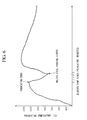
- the inventors of the present invention investigated the extent to which the temperature of the outside surface of the nozzle reduces from the end of preheating to the start of molten steel pouring, using an actual continuous casting nozzle requiring seven minutes from the end of gas burner preheating until molten steel pouring begins.
- the results are shown in FIG 6 .
- a large drop in temperature was observed of approximately 200°C at 5 minutes after gas burner preheating ended and almost 300°C at seven minutes. Therefore, even if preheating is initially performed to 1000°C or higher, when pouring starts, the temperature of the nozzle outside surface reduces to less than 1000°C (less than 800°C in FIG.
- the present invention has the following aspects:
- the outside surface of the continuous casting nozzle is maintained at 1000°C or higher by the nozzle heating device.
- the temperature of the continuous casting nozzle can be raised and maintained without problems such as current leakage or the deterioration of refractory materials occurring, thereby preventing the adhesion of non-metallic oxides and base metal.
- blocking of the continuous casting nozzle by adhesion can be prevented and the number of consecutive continuous casting charges can be increased.
- a continuous casting method of the present invention the outside surface of a continuous casting nozzle which supplies molten metal into a mold while immersed in the molten metal in the mold is heated to 1000°C or higher by a nozzle heating device comprising a radiant heater, while the molten metal passes through the continuous casting nozzle.
- a nozzle heating device comprising a radiant heater
- the molten metal passes through the continuous casting nozzle.
- preheating when performing preheating the submerged nozzle can be preheated at a standby position. Furthermore, in an embodiment of the present invention, preheating can be performed as the tundish is being moved to the casting position. Moreover in another aspect of the present invention, preheating begins with the tundish located at the casting position, enabling nozzle heating to be performed without interruption at the beginning of and during the casting process. Conventionally, the submerged nozzle heated by a gas burner radiates heat and becomes a stand-by state during the interval from when molten steel is poured from the ladle into the tundish until the molten steel in the tundish reaches the prescribed quantity.
- the inside surface temperature of the nozzle falls from approximately 1100°C to 1050°C after 4 to 5 minutes, and the outside surface temperature falls to approximately 750 to 800°C.
- the outside surface temperature of the submerged nozzle is 900°C or thereabouts, showing that a large amount of heat had been released from the outside surface of the submerged nozzle to the atmosphere. Such heat release is a major cause of base metal adhesion to the inside surface of the nozzle.
- the present invention fundamentally reexamines the approach to these problems, and provides a method of continually heating the nozzle outside surface, including the period from the end of preheating to the midst of molten metal (molten steel) pouring, preventing the discharge of heat from the nozzle outside surface.
- FIG. 6 which shows measurements of the outside surface temperature of the continuous casting nozzle from the start of preheating to the midst of molten steel pouring, in the period from the end of preheating to the midst of molten steel pouring, the nozzle outside surface temperature is lowest at the start of molten steel pouring.
- the wall thickness of the nozzle is normally 30 mm or thereabouts, which is generally constant regardless of nozzle type.
- the thermal conductivity of the nozzle wall because the temperature difference between the outside surface and inside surface of the nozzle does not differ to any great degree between nozzle types (for example a difference of 50 to 100°C), the present invention is applicable to any nozzle type.
- the temperature control reference for when heating external heating in an amount equal to or greater than the amount of heat lost to heat transfer through the nozzle wall during molten steel pouring is made the reference, so that the outside surface of the submerged nozzle can be maintained at 1000°C or higher.
- the reason is that when the outside surface temperature of the submerged nozzle is less than 1000°C, as described above, significant heat is discharged to the atmosphere from the nozzle outside surface, increasing the likelihood of base metal adhering to the nozzle inside surface.
- a location near where the submerged nozzle attaches is made the reference position.
- the submerged nozzle is subjected to radiant heating from the molten steel in the mold during pouring, it is desirable to make the outside surface temperature at the neck region where the submerged nozzle is secured, where the effect of this radiant heating is judged to be minimal, a reference point.
- the heated range in the height direction of the submerged nozzle due to the nozzle heating device this is preferably 50% or more of the height dimension of the submerged nozzle, and is such a range that the nozzle heating device does not contact the molten steel in the mold.
- a radiant heater with an absolute heating temperature of 1000°C or higher is necessary, but particularly, most desirable is a heater with a fast heating rate and a high absolute heating temperature.
- Examples of such a heater include carbon heaters, silicon carbide (SiC) heaters, and molybdenum silicide (MoSi 2 ) heaters.
- Carbon heaters have a fast heating rate and are therefore suitable for rapid heating, but because the carbon serving that is the heating element is prone to oxidative degradation, silica glass is provided as a protective tube around the outer periphery of the carbon heater.
- this protective tube is relatively low at 1100°C or thereabouts, when working with higher temperatures a SiC or MoSi 2 heater is preferred.
- a SiC heater typically operates at a temperature of 1450°C, but can rise in temperature relatively quickly, at a rate of 20°C/minute or thereabouts.
- a MoSi 2 heater is capable of operating at a temperature of 1700°C, but because the thermal shock resistance of the heater itself is poor, the rate of temperature increase is often limited to 5 to 10°C/minute or thereabouts.
- a SiC heater because the outside surface is protected by an oxide layer made of SiO 2 , a SiC heater can be used in open air without a protective tube.
- the heater can be used in open air without a protective tube. Moreover, the heater can be disposed in the same manner as a SiC heater. Accordingly, in consideration of the heating temperature and preheating time of the submerged nozzle, it is preferable to select the heater type.
- a device is employed which comprises; an insulator provided so as to surround the outside of the submerged nozzle serving as the continuous casting nozzle leaving a gap, and a carbon heater provided on the inside surface of the insulator facing the submerged nozzle.
- the insulator is a cylindrical shape, such as a cylinder, elliptical cylinder, or polygonal cylinder.
- the gap between the outside surface of the submerged nozzle and the carbon heater provided on the inside surface of the insulator of the nozzle heating device is preferably 50 mm or less. If a wider gap is used, the heating efficiency of the submerged nozzle worsens. On the other hand, if too narrow a gap is used, it cannot accommodate variations in the mounting accuracy of the submerged nozzle.
- a gap is preferably secured which is as narrow as possible within an approximate ⁇ 10 mm tolerance of the mounting accuracy of the submerged nozzle.
- the submerged nozzle can be efficiently heated without external dissipation of the heat from the carbon heater. Furthermore, because there is no need to embed a heating resistor or the like in the continuous casting submerged nozzle, and the nozzle need not be processed by expensive materials, a simple construction can be employed. As a result, the manufacturing costs of the continuous casting submerged nozzle can be kept low. In addition, because there is design flexibility in terms of the shape of the carbon heater, with little exactness required in the placement and the like thereof, the method of the present embodiment can be applied easily to actual operations.
- the heater when a carbon heater is employed as the radiant heater, preferably the heater is covered by a ceramic protective tube with reduced internal pressure.
- a ceramic protective tube typically glass is used, but at temperatures exceeding 1000°C, in the case of silicate glass, because devitrification occurs with repeated use and softening deformation occurs at high temperatures, heating in excess of 1000°C cannot be performed.
- crystallized glass or sapphire glass or the like is most preferably used as the material for the protective tube.
- the insulator is composed of multiple insulating segments.
- the insulator is a cylindrical shape
- an insulator can be employed which is divided into two segments along a single plane that includes the axis of the cylindrical body.
- the carbon heaters or the like serving as the radiant heaters disposed inside the insulator are preferably supplied with power independently at each of the insulating segments.
- a fundamental aspect of the present invention is that, from the start of preheating to the midst of molten steel pouring, an external radiant heater is used to perform heating.
- an external radiant heater is used to perform heating.
- a conventional technique using a gas burner or the like may also be used. In this case, because in most cases an insulating material is provided around the outside of the submerged nozzle during preheating, after preheating the insulating material is removed from regions of the nozzle outside surface which are to be heated by the radiant heater, before transitioning to heating by the radiant heater.
- the radiant heating efficiency can be improved. If a molybdenum heater is used as the radiant heater, because the heating rate is relatively slow, by performing all or the initial stage of preheating using a conventional technique (such as a gas burner) as described above, the preheating time can be reduced. Moreover, when using a carbon heater, during molten steel pouring, because there is a possibility that the rise in the nozzle outside surface temperature might cause the carbon heater protective tube to overheat and suffer damage, even more preferably an insulating material is provided between the carbon heater and the submerged nozzle.
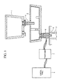
- FIG. 1 shows a continuous casting facility according to the present embodiment.
- This continuous casting facility comprises; a ladle 1, a tundish 2, and a mold 3. Furthermore, although omitted from the figure, at the bottom of the mold 3, rollers are provided.
- molten steel that has undergone secondary smelting is supplied to the ladle 1 and transported, the molten steel inside the ladle 1 is supplied to the tundish 2, and the molten steel is then supplied into the mold 3 from an opening formed in the base of the tundish 2.
- the supply of molten steel from the ladle 1 to the tundish 2 is performed by a long nozzle 4 provided on a molten steel supply opening formed at the base of the ladle 1. Moreover the supply of molten steel from the tundish 2 to the mold 3 is performed by an submerged nozzle 5 provided on a molten steel supply opening formed at the base of the tundish 2.
- the submerged nozzle 5 is heated by a nozzle heating device 6 disposed directly above the mold 3.
- a transformer 7 and a control panel 8 are connected to the nozzle heating device 6 via the transformer 7, and the nozzle heating device 6 heats the submerged nozzle 5 by the supplied power.
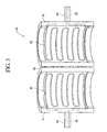
- the nozzle heating device 6 has a cylindrical shape, and as shown in FIG. 2 , comprises two insulating sections 61 divided at a single virtual plane that includes the axis of the cylinder, and carbon heaters 62 provided in the respective cylinder inside surfaces of the insulating sections 61.
- a hinge 63 is provided at one edge of the insulating sections 61, and by means of this hinge 63 the two segments of the nozzle heating device 6 are able to open and close.
- a support arm 64 is provided at the other edge of the insulating sections 61. During heating of the submerged nozzle 5, this support arm 64 supports the nozzle heating device 6 in a suspended manner directly above the mold 3.
- the insulating sections 61 are thick walled molded components with a semi-circular cross section, and are composed of refractory materials or the like so as to withstand the heat of the molten steel.
- the carbon heaters 62 are provided on the inside surface of the insulating sections 61.
- the radius of the semicircle that forms the inside surface of the insulating section 61 is such that, when disposed coaxially with the circular cross section of the submerged nozzle 5, a gap of 50 mm or less for example is formed between the carbon heater 62 and the outside surface of the submerged nozzle 5.
- the height dimension of the insulating sections 61 is such that at least 50% of the height of the submerged nozzle 5 is covered, and is preferably such that the entirety of the submerged nozzle 5 can be heated.
- the carbon heater 62 extends along the axial direction of the cylinder formed by combining the two insulating sections 61, and bends 180 degrees near the end of the insulating sections 61. As a result, the carbon heater 62 meanders back and forth along the circumferential direction of the inside surface of the insulating sections 61.
- This carbon heater 62 comprises a carbon heating element, and a protective tube which covers this carbon heating element, and by depressurizing the inside of the protective tube, the carbon heating element is prevented from contacting the atmosphere and suffering oxidative degradation.
- the material of the protective tube because the outside surface of the submerged nozzle 5 is heated to 1000°C, the material used must be able to withstand such a temperature. For example, crystallized glass or sapphire glass can be used.
- Conductive wires 65 are connected to the ends of the carbon heaters 62.
- the conductive wires 65 pass through the inside of the insulating sections 61, lead out from the support arms 64 to the outside, and connect to the transformer 7 described above.
- the conductive wires 65 are connected independently to the carbon heater 62 of each insulating section 61, so that the wires do not interfere and break when the two insulating sections 61 are changed from a jointly closed state to an open state.
- a nozzle heating device 6 is employed which incorporates a carbon heater 62 in a meandering state along the circumferential direction on the inside surface of the insulating sections 61.
- the present embodiment is not limited to this configuration, and as shown by the modified example in FIG.
- a nozzle heating device 6A in which the carbon heaters 62 are disposed so as to meander in the axial direction of the cylindrical body formed by combining the pair of insulating sections 61 can be employed.
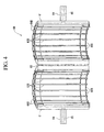
- a nozzle heating device 6B can be employed in which a plurality of SiC heaters 62B are disposed.
- This nozzle heating device 6B has a construction in which the plurality of easily retained rod shaped SiC heaters 62B are disposed in parallel, and these SiC heaters 62B are connected in series by wires 66B, and is otherwise constructed in the same manner as FIG. 2 .
- the nozzle heating device 6 described above When the nozzle heating device 6 described above is fitted to the continuous casting facility, with the submerged nozzle 5 fitted to the tundish 2, the nozzle heating device 6 is placed near the submerged nozzle 5 with the insulating sections 61 still open. Subsequently, the insulating sections 61 are closed so as to surround the submerged nozzle 5, and are held directly above the mold 3 by the support arm 64. Next, a continuous casting method using this nozzle heating device 6 is described. First, power is supplied to the nozzle heating device 6 to preheat the submerged nozzle 5. When the outside surface of the submerged nozzle 5 reaches equal to or higher than 1000°C. continuous casting begins with the supply of molten steel from the ladle 1 to the tundish 2.
- FIG. 5A and FIG. 5B show enlarged views of an example in which the surface of the submerged nozzle 5 in FIG. 1 is covered by an insulating material.
- FIG. 5A is an enlarged cross-sectional view of the nozzle heating device 6 prior to molten steel pouring.
- FIG. 5B is an enlarged cross-sectional view of the nozzle heating device 6 during molten steel pouring (during casting).
- the nozzle heating device 6 By attaching the nozzle heating device 6 to the outer periphery of the center in the length direction of the submerged nozzle 5, and attaching a first insulating material 67C and a second insulating material 68C above and below the nozzle heating device 6, heat loss from the portion not covered by the nozzle heating device 6 can be prevented.
- the second insulating material 68C covering the lower part of the submerged nozzle 5 to the bottom end the amount of heat released from the parts of the submerged nozzle 5 not covered by the nozzle heating device 6 can be minimized.
- the portion immersed in the molten steel S inside the mold 3 at the beginning of casting is dissolved by the heat of the molten steel S, and does not require removal. This is shown in FIG. 5B .
- the portion where the nozzle heating device 6 is located to protect the carbon heater 62 during casting, functionality that enables the attachment and removal of a third insulating material 69C between the submerged nozzle 5 and the carbon heater 62 can be provided.
- the third insulating material 69C is preferably also provided in the construction shown in FIG. 1 .
- the third insulating material 69C need not be provided. Furthermore, in FIG. 5A and FIG. 5B , as the height dimension of the nozzle heating device 6, sufficient height to cover only the third insulating material 69C is exemplified. However a height dimension may be used which also covers at least one of the first insulating material 67C and the second insulating material 68C.
- the nozzle heating device 6A comprising the carbon heater 62 shown in FIG. 3 was used.
- the submerged nozzle 5 was preheated at the nozzle standby position using the nozzle heating device 6A, and then, heating of the submerged nozzle 5 by the nozzle heating device 6A was continued while the submerged nozzle 5 was fitted to the tundish 2.
- molten steel pouring supplied to the submerged nozzle 5 after attaching the third insulating material 69C between the submerged nozzle 5 and the carbon heater 62 (to prevent the heater protective tube from overheating when the outside surface temperature of the submerged nozzle 5 is raised by the molten metal inside the submerged nozzle 5 after casting starts.
- example 2 using the SiC heaters 62B shown in FIG. 4 instead of the carbon heater 62 of example 1 above, in the same manner as in example 1, first the submerged nozzle 5 was preheated at the nozzle standby position using the nozzle heating device 6A. Then, heating of the submerged nozzle 5 by the nozzle heating device 6B was continued while the submerged nozzle 5 was fitted to the tundish 2.
- the SiC heaters 62B differs from the carbon heater 62, because there was no need to attach the third insulating material 69C between the submerged nozzle 5 and the SiC heaters 62B, heating of the submerged nozzle 5 was not interrupted. That the outside surface temperature of the submerged nozzle 5 was 1550°C at the start of molten steel pouring, was confirmed by a thermocouple attached to the outside surface of the submerged nozzle 5.
- example 3 instead of the carbon heater 62 of example 1, the material of the carbon heater 62B shown in FIG. 4 was changed from SiC to MoSi 2 , and the construction was changed from a rod shape to a U shape, giving MoSi 2 heaters in which the top ends of adjacent U-shaped heaters were connected in series. Then in the same manner as in example 1, first the submerged nozzle 5 was preheated at the nozzle standby position using the nozzle heating device 6B. Then, heating of the submerged nozzle 5 by the nozzle heating device 6B was continued while the submerged nozzle 5 was fitted to the tundish 2.
- the MoSi 2 heater differs from the carbon heater 62, because there was no need to attach the third insulating material 69C between the submerged nozzle 5 and the MoSi 2 heaters, heating of the submerged nozzle 5 was not interrupted. That the outside surface temperature of the submerged nozzle 5 was 1600°C at the start of molten steel pouring, was confirmed by a thermocouple attached to the outside surface of the submerged nozzle 5.
- the outside surface of the continuous casting nozzle is maintained at 1000°C or higher by a nozzle heating device.
- the temperature of the continuous casting nozzle can be raised and maintained without problems such as current leakage or the deterioration of refractory materials occurring, thereby preventing the adhesion of non-metallic oxides and base metal.
- blocking of the continuous casting nozzle by adhesion can be prevented, and the number of consecutive continuous casting charges can be increased.
Landscapes
- Engineering & Computer Science (AREA)
- Mechanical Engineering (AREA)
- Casting Support Devices, Ladles, And Melt Control Thereby (AREA)
Applications Claiming Priority (2)
| Application Number | Priority Date | Filing Date | Title |
|---|---|---|---|
| JP2008332935 | 2008-12-26 | ||
| PCT/JP2009/007362 WO2010073736A1 (ja) | 2008-12-26 | 2009-12-28 | 連続鋳造方法及びノズル加熱装置 |
Publications (2)
| Publication Number | Publication Date |
|---|---|
| EP2380680A1 true EP2380680A1 (de) | 2011-10-26 |
| EP2380680A4 EP2380680A4 (de) | 2017-04-26 |
Family
ID=42287368
Family Applications (1)
| Application Number | Title | Priority Date | Filing Date |
|---|---|---|---|
| EP09834542.4A Withdrawn EP2380680A4 (de) | 2008-12-26 | 2009-12-28 | Stranggiessverfahren und düsenheizvorrichtung |
Country Status (8)
| Country | Link |
|---|---|
| US (1) | US8360136B2 (de) |
| EP (1) | EP2380680A4 (de) |
| JP (1) | JP4585606B2 (de) |
| KR (1) | KR101282455B1 (de) |
| CN (1) | CN102264489B (de) |
| BR (1) | BRPI0923132B1 (de) |
| CA (1) | CA2748179C (de) |
| WO (1) | WO2010073736A1 (de) |
Cited By (1)
| Publication number | Priority date | Publication date | Assignee | Title |
|---|---|---|---|---|
| AT527876A1 (de) * | 2024-01-12 | 2025-07-15 | Fill Gmbh | Verfahren zum Aufheizen einer Lanze oder eines Steigrohres, sowie Heizstation zum Durchführen des Verfahrens |
Families Citing this family (12)
| Publication number | Priority date | Publication date | Assignee | Title |
|---|---|---|---|---|
| DE102010050936A1 (de) * | 2010-11-11 | 2012-05-16 | Heraeus Electro-Nite International N.V. | Bodenausgussdüse für die Anordnung im Boden eines metallurgischen Gefäßes |
| MX349696B (es) * | 2012-03-28 | 2017-08-09 | Arcelormittal Investigacion Y Desarrollo Sl | Equipo de colada continua. |
| CN102814494A (zh) * | 2012-08-10 | 2012-12-12 | 沈阳东北大学冶金技术研究所有限公司 | 一种连铸中间包钢液加热方法 |
| JP6154708B2 (ja) * | 2013-09-27 | 2017-06-28 | 日新製鋼株式会社 | 連続鋳造方法 |
| JP5723044B1 (ja) * | 2014-05-30 | 2015-05-27 | 榮子 山田 | 鋼の連続鋳造用タンディシュノズル及び連続鋳造方法 |
| JP5937645B2 (ja) * | 2014-07-23 | 2016-06-22 | 明智セラミックス株式会社 | 連続鋳造用ノズルの予熱装置 |
| KR101675315B1 (ko) * | 2014-12-11 | 2016-11-11 | 주식회사 포스코 | 용탕 분사용 노즐 보온 장치 |
| JP6523710B2 (ja) * | 2015-02-27 | 2019-06-05 | 黒崎播磨株式会社 | スライディングノズル装置のスライド金枠と駆動装置との連結切り替え構造 |
| TWI654042B (zh) | 2017-02-21 | 2019-03-21 | 日商新日鐵住金股份有限公司 | 鋼之熔製方法 |
| KR101876188B1 (ko) * | 2017-10-17 | 2018-07-10 | (주)파인엔클린 | 고순도 아연 회수 및 주조 장치 |
| JP2019136747A (ja) * | 2018-02-13 | 2019-08-22 | 明智セラミックス株式会社 | 連続鋳造用ノズルの予熱装置 |
| WO2020235235A1 (ja) * | 2019-05-22 | 2020-11-26 | 本田技研工業株式会社 | 低圧鋳造装置 |
Family Cites Families (21)
| Publication number | Priority date | Publication date | Assignee | Title |
|---|---|---|---|---|
| US3604598A (en) * | 1969-07-09 | 1971-09-14 | United States Steel Corp | Outlet passage construction for teeming vessels |
| JPS49138116U (de) * | 1973-03-29 | 1974-11-28 | ||
| JPS5474698A (en) * | 1977-11-28 | 1979-06-14 | Univ Tohoku | Superconductive thin band and method of fabricating same |
| SE448381B (sv) * | 1978-09-19 | 1987-02-16 | Tsuya Noboru | Sett att framstella ett tunt band av kiselstal, tunt kiselstalband och anvendning av dylikt |
| JPS62224473A (ja) * | 1986-03-25 | 1987-10-02 | Daido Steel Co Ltd | 取鍋用耐火物製棒状体の予熱装置 |
| JPH01170561A (ja) * | 1987-12-24 | 1989-07-05 | Nippon Steel Corp | 溶融金属流通管の通電加熱方法 |
| JPH01205858A (ja) * | 1988-02-10 | 1989-08-18 | Daido Steel Co Ltd | 連続鋳造用侵漬ノズル |
| JPH01219027A (ja) * | 1988-02-25 | 1989-09-01 | Shigeru Yoshida | 可傾式ガラス溶融電気炉 |
| JPH06552U (ja) | 1992-05-29 | 1994-01-11 | 川崎製鉄株式会社 | 通電発熱式の連続鋳造用浸漬ノズル |
| EP0673699B1 (de) | 1993-09-16 | 2000-10-25 | Rheo-Technology, Ltd | Verfahren zur herstellung dünner gussstücke mittels kontinuierlichem giessen |
| JP3532041B2 (ja) * | 1996-10-18 | 2004-05-31 | 新日本製鐵株式会社 | 連続鋳造用浸漬ノズルの予熱装置 |
| JP4185194B2 (ja) * | 1997-07-31 | 2008-11-26 | コバレントマテリアル株式会社 | カーボンヒータ |
| TW452826B (en) * | 1997-07-31 | 2001-09-01 | Toshiba Ceramics Co | Carbon heater |
| JP4697909B2 (ja) | 2000-05-25 | 2011-06-08 | コバレントマテリアル株式会社 | カーボンワイヤー発熱体封入ヒータ |
| JP2002336942A (ja) * | 2001-05-16 | 2002-11-26 | Nkk Corp | 連続鋳造用浸漬ノズルおよび連続鋳造方法 |
| DE10132575C1 (de) | 2001-07-10 | 2002-07-04 | Heraeus Electro Nite Int | Feuerfester Ausguss |
| JP2004243407A (ja) | 2003-02-17 | 2004-09-02 | Sumitomo Metal Ind Ltd | Mg合金溶湯の連続鋳造方法 |
| JP4660343B2 (ja) * | 2004-11-24 | 2011-03-30 | 新日本製鐵株式会社 | 溶融金属の注入用ノズルの加熱装置 |
| JP4734201B2 (ja) | 2006-08-31 | 2011-07-27 | 新日本製鐵株式会社 | 連続鋳造方法 |
| CN101157557B (zh) * | 2007-09-29 | 2010-12-15 | 中南大学 | 二硅化钼赛隆复合发热体 |
| JP5015053B2 (ja) | 2008-03-28 | 2012-08-29 | 新日本製鐵株式会社 | 連続鋳造用浸漬ノズルの予熱方法及び連続鋳造方法 |
-
2009
- 2009-12-25 JP JP2009294823A patent/JP4585606B2/ja active Active
- 2009-12-28 CN CN200980152024.6A patent/CN102264489B/zh active Active
- 2009-12-28 EP EP09834542.4A patent/EP2380680A4/de not_active Withdrawn
- 2009-12-28 KR KR1020117014387A patent/KR101282455B1/ko not_active Expired - Fee Related
- 2009-12-28 WO PCT/JP2009/007362 patent/WO2010073736A1/ja not_active Ceased
- 2009-12-28 US US13/141,662 patent/US8360136B2/en active Active
- 2009-12-28 BR BRPI0923132-3A patent/BRPI0923132B1/pt active IP Right Grant
- 2009-12-28 CA CA2748179A patent/CA2748179C/en not_active Expired - Fee Related
Non-Patent Citations (1)
| Title |
|---|
| See references of WO2010073736A1 * |
Cited By (2)
| Publication number | Priority date | Publication date | Assignee | Title |
|---|---|---|---|---|
| AT527876A1 (de) * | 2024-01-12 | 2025-07-15 | Fill Gmbh | Verfahren zum Aufheizen einer Lanze oder eines Steigrohres, sowie Heizstation zum Durchführen des Verfahrens |
| EP4585327A1 (de) * | 2024-01-12 | 2025-07-16 | Fill Gesellschaft m.b.H. | Verfahren zum aufheizen einer lanze oder eines steigrohres, sowie heizstation zum durchführen des verfahrens |
Also Published As
| Publication number | Publication date |
|---|---|
| JP2010167495A (ja) | 2010-08-05 |
| US20110253337A1 (en) | 2011-10-20 |
| JP4585606B2 (ja) | 2010-11-24 |
| KR101282455B1 (ko) | 2013-07-04 |
| CA2748179C (en) | 2013-08-20 |
| CN102264489A (zh) | 2011-11-30 |
| BRPI0923132A2 (pt) | 2020-08-25 |
| BRPI0923132B1 (pt) | 2022-02-22 |
| EP2380680A4 (de) | 2017-04-26 |
| CA2748179A1 (en) | 2010-07-01 |
| CN102264489B (zh) | 2014-01-29 |
| WO2010073736A1 (ja) | 2010-07-01 |
| US8360136B2 (en) | 2013-01-29 |
| KR20110085004A (ko) | 2011-07-26 |
Similar Documents
| Publication | Publication Date | Title |
|---|---|---|
| US8360136B2 (en) | Continuous casting method and nozzle heating device | |
| EP1836015B1 (de) | Laufrinne zum giessen von geschmolzenen schmelzen | |
| CN107116205A (zh) | 金属传送装置 | |
| GB2522349A (en) | Metal transfer device | |
| CN112210676A (zh) | 一种电磁感应发热复合坩埚 | |
| CN101888910B (zh) | 浸渍喷嘴及连续铸造方法 | |
| KR101206559B1 (ko) | 용해로의 송풍구 장치 | |
| JP2007111744A (ja) | 誘導加熱式タンディッシュ及びその補修方法 | |
| JP2011099840A (ja) | 取鍋用連続測温プローブ | |
| JP5850072B2 (ja) | 高温溶融物用ノズルおよびそれを用いた鋳造方法 | |
| JP4467554B2 (ja) | 溶鋼注湯用ノズルの予熱方法 | |
| JP4270739B2 (ja) | 熱間加工用支持体 | |
| US12089301B1 (en) | Material, apparatus, and method for electrically shielding heated components | |
| JP7234768B2 (ja) | 浸漬ノズルの予熱方法 | |
| JP2005021927A (ja) | 耐火物消化と熱衝撃割れを防止した連続鋳造方法 | |
| JP2010173892A (ja) | 溶融ガラス流出制御装置及びガラス成形体の製造方法 | |
| JP2003266156A (ja) | 鋼の連続鋳造用ノズル |
Legal Events
| Date | Code | Title | Description |
|---|---|---|---|
| PUAI | Public reference made under article 153(3) epc to a published international application that has entered the european phase |
Free format text: ORIGINAL CODE: 0009012 |
|
| 17P | Request for examination filed |
Effective date: 20110720 |
|
| AK | Designated contracting states |
Kind code of ref document: A1 Designated state(s): AT BE BG CH CY CZ DE DK EE ES FI FR GB GR HR HU IE IS IT LI LT LU LV MC MK MT NL NO PL PT RO SE SI SK SM TR |
|
| DAX | Request for extension of the european patent (deleted) | ||
| RAP1 | Party data changed (applicant data changed or rights of an application transferred) |
Owner name: NIPPON STEEL & SUMITOMO METAL CORPORATION |
|
| RA4 | Supplementary search report drawn up and despatched (corrected) |
Effective date: 20170324 |
|
| RIC1 | Information provided on ipc code assigned before grant |
Ipc: H05B 3/44 20060101ALI20170320BHEP Ipc: H05B 3/14 20060101ALI20170320BHEP Ipc: B22D 11/10 20060101AFI20170320BHEP Ipc: B22D 41/60 20060101ALI20170320BHEP |
|
| 17Q | First examination report despatched |
Effective date: 20180205 |
|
| RAP1 | Party data changed (applicant data changed or rights of an application transferred) |
Owner name: NIPPON STEEL CORPORATION |
|
| GRAP | Despatch of communication of intention to grant a patent |
Free format text: ORIGINAL CODE: EPIDOSNIGR1 |
|
| STAA | Information on the status of an ep patent application or granted ep patent |
Free format text: STATUS: GRANT OF PATENT IS INTENDED |
|
| INTG | Intention to grant announced |
Effective date: 20200626 |
|
| STAA | Information on the status of an ep patent application or granted ep patent |
Free format text: STATUS: THE APPLICATION IS DEEMED TO BE WITHDRAWN |
|
| 18D | Application deemed to be withdrawn |
Effective date: 20201107 |