EP2381106A2 - Hermetischer verdichter - Google Patents
Hermetischer verdichter Download PDFInfo
- Publication number
- EP2381106A2 EP2381106A2 EP09838928A EP09838928A EP2381106A2 EP 2381106 A2 EP2381106 A2 EP 2381106A2 EP 09838928 A EP09838928 A EP 09838928A EP 09838928 A EP09838928 A EP 09838928A EP 2381106 A2 EP2381106 A2 EP 2381106A2
- Authority
- EP
- European Patent Office
- Prior art keywords
- connector
- refrigerant
- suction
- pressure
- hermetic
- Prior art date
- Legal status (The legal status is an assumption and is not a legal conclusion. Google has not performed a legal analysis and makes no representation as to the accuracy of the status listed.)
- Granted
Links
Images


Classifications
-
- F—MECHANICAL ENGINEERING; LIGHTING; HEATING; WEAPONS; BLASTING
- F04—POSITIVE - DISPLACEMENT MACHINES FOR LIQUIDS; PUMPS FOR LIQUIDS OR ELASTIC FLUIDS
- F04B—POSITIVE-DISPLACEMENT MACHINES FOR LIQUIDS; PUMPS
- F04B39/00—Component parts, details, or accessories, of pumps or pumping systems specially adapted for elastic fluids, not otherwise provided for in, or of interest apart from, groups F04B25/00 - F04B37/00
- F04B39/0027—Pulsation and noise damping means
- F04B39/0033—Pulsation and noise damping means with encapsulations
- F04B39/0038—Pulsation and noise damping means with encapsulations of inlet or outlet channels
-
- F—MECHANICAL ENGINEERING; LIGHTING; HEATING; WEAPONS; BLASTING
- F04—POSITIVE - DISPLACEMENT MACHINES FOR LIQUIDS; PUMPS FOR LIQUIDS OR ELASTIC FLUIDS
- F04B—POSITIVE-DISPLACEMENT MACHINES FOR LIQUIDS; PUMPS
- F04B39/00—Component parts, details, or accessories, of pumps or pumping systems specially adapted for elastic fluids, not otherwise provided for in, or of interest apart from, groups F04B25/00 - F04B37/00
- F04B39/0027—Pulsation and noise damping means
- F04B39/0055—Pulsation and noise damping means with a special shape of fluid passage, e.g. bends, throttles, diameter changes, pipes
- F04B39/0061—Pulsation and noise damping means with a special shape of fluid passage, e.g. bends, throttles, diameter changes, pipes using muffler volumes
-
- F—MECHANICAL ENGINEERING; LIGHTING; HEATING; WEAPONS; BLASTING
- F25—REFRIGERATION OR COOLING; COMBINED HEATING AND REFRIGERATION SYSTEMS; HEAT PUMP SYSTEMS; MANUFACTURE OR STORAGE OF ICE; LIQUEFACTION SOLIDIFICATION OF GASES
- F25B—REFRIGERATION MACHINES, PLANTS OR SYSTEMS; COMBINED HEATING AND REFRIGERATION SYSTEMS; HEAT PUMP SYSTEMS
- F25B31/00—Compressor arrangements
-
- F—MECHANICAL ENGINEERING; LIGHTING; HEATING; WEAPONS; BLASTING
- F05—INDEXING SCHEMES RELATING TO ENGINES OR PUMPS IN VARIOUS SUBCLASSES OF CLASSES F01-F04
- F05B—INDEXING SCHEME RELATING TO WIND, SPRING, WEIGHT, INERTIA OR LIKE MOTORS, TO MACHINES OR ENGINES FOR LIQUIDS COVERED BY SUBCLASSES F03B, F03D AND F03G
- F05B2260/00—Function
- F05B2260/96—Preventing, counteracting or reducing vibration or noise
- F05B2260/962—Preventing, counteracting or reducing vibration or noise by means creating "anti-noise"
-
- F—MECHANICAL ENGINEERING; LIGHTING; HEATING; WEAPONS; BLASTING
- F05—INDEXING SCHEMES RELATING TO ENGINES OR PUMPS IN VARIOUS SUBCLASSES OF CLASSES F01-F04
- F05B—INDEXING SCHEME RELATING TO WIND, SPRING, WEIGHT, INERTIA OR LIKE MOTORS, TO MACHINES OR ENGINES FOR LIQUIDS COVERED BY SUBCLASSES F03B, F03D AND F03G
- F05B2280/00—Materials; Properties thereof
- F05B2280/40—Organic materials
- F05B2280/4004—Rubber
-
- F—MECHANICAL ENGINEERING; LIGHTING; HEATING; WEAPONS; BLASTING
- F25—REFRIGERATION OR COOLING; COMBINED HEATING AND REFRIGERATION SYSTEMS; HEAT PUMP SYSTEMS; MANUFACTURE OR STORAGE OF ICE; LIQUEFACTION SOLIDIFICATION OF GASES
- F25B—REFRIGERATION MACHINES, PLANTS OR SYSTEMS; COMBINED HEATING AND REFRIGERATION SYSTEMS; HEAT PUMP SYSTEMS
- F25B2500/00—Problems to be solved
- F25B2500/12—Sound
-
- Y—GENERAL TAGGING OF NEW TECHNOLOGICAL DEVELOPMENTS; GENERAL TAGGING OF CROSS-SECTIONAL TECHNOLOGIES SPANNING OVER SEVERAL SECTIONS OF THE IPC; TECHNICAL SUBJECTS COVERED BY FORMER USPC CROSS-REFERENCE ART COLLECTIONS [XRACs] AND DIGESTS
- Y10—TECHNICAL SUBJECTS COVERED BY FORMER USPC
- Y10S—TECHNICAL SUBJECTS COVERED BY FORMER USPC CROSS-REFERENCE ART COLLECTIONS [XRACs] AND DIGESTS
- Y10S417/00—Pumps
Definitions
- the present invention relates to a hermetic compressor, and more particularly, to a hermetic compressor which can reduce the noise by regulating a suction pressure in a connector enabling a suction pipe of a hermetic container and a suction muffler to communicate with each other.
- a hermetic compressor in general, includes a compression mechanism unit compressing refrigerant by a reciprocating motion, a motor mechanism unit supplying power to the compression mechanism unit, and a hermetic container accommodating the compression mechanism unit and the motor mechanism unit an airtight state.
- the hermetic compressor which is a component constituting a freezing system such as a refrigerator, etc., serves to phase-shift low-temperature low-pressure gas refrigerant into high-temperature high-pressure gas refrigerant. Such phase shift can be implemented by a compressive force of a piston linearly reciprocated in a cylinder.
- FIG. 1 is a view of an example of a conventional hermetic compressor
- FIG. 2 is a graph of the noise and the refrigerant velocity in the example of the conventional hermetic compressor.
- a given lower container 1 a and a given upper container 1 b are coupled to constitute a hermetic container 1
- a motor mechanism unit 4 composed of a stator 2 and a rotor 3 is installed in the hermetic container 1
- a plurality of compression components are installed on the upper side of the motor mechanism unit 4.
- a plurality of springs S are supported on the lower side of the stator 2 to absorb shock applied to the stator 2 during the rotation of the rotor 3, and components for transferring power are installed between the motor mechanism unit 4 and the compression components.
- the components for transferring power include a rotational shaft 5, a cylinder block 6, a sleeve 7 and a connecting rod 8.
- the rotational shaft 5 is press-fit into a press-fit hole 3a penetrating through the center of the rotor 3 in the vertical direction and rotatably inserted into the cylinder block 6.
- An eccentric portion 5a provided at a top end portion of the rotational shaft 5 is coupled to the sleeve 7, and the connecting rod 8 converting a rotational motion into a linear motion is coupled to the sleeve 7.
- the compression components include a cylinder 9 and a piston 10.
- the cylinder 9 is provided at one side of an upper portion of the cylinder block 6, and the piston 10 is inserted into the cylinder 9 and connected to the connecting rod 8 to be linearly reciprocated.
- a valve device 11 for use in sucking/discharging refrigerant gas into/from a compression space of the cylinder 9 is coupled to an one-side opening portion of the cylinder 9, and a head cover 12 partitioned into a suction space and a discharge space to separate suction refrigerant from discharge refrigerant is coupled to the outside of the valve device 11.
- a suction muffler (not shown) is coupled to the lower side of the head cover 12 to communicate therewith.
- the suction muffler communicates with a suction pipe 14 provided in the hermetic container 1 via a connector (not shown). Moreover, a discharge muffler (not shown) for reducing the noise of discharge refrigerant may be provided on the upper side of the head cover 12 to communicate therewith. The discharge muffler communicates with a discharge pipe 15 provided in the hermetic container 1 via a loop pipe 16.
- the operation of the hermetic compressor will be described.
- the rotor 3 is rotated due to the interaction between the stator 2 and the rotor 3, and the rotational shaft 5 coupled to the rotor 3 is rotated.
- the piston 10 is linearly reciprocated in the compression space in the cylinder 9.
- refrigerant is introduced into the valve device 11 through the suction muffler and the suction space of the head cover 12 via the suction pipe 14.
- a suction valve (not shown) of the valve device 11 is open, the refrigerant is sucked into the compression space in the cylinder 9.
- the refrigerant compressed in the compression space opens a discharge valve (not shown), is discharged into the discharge space of the head cover 12, and is discharged to the outside through the discharge pipe 15 of the hermetic container 1 via the discharge muffler and the loop pipe 16.
- the adhesion of the connector is designed to be higher than an inner pressure of the suction pipe such that the elastic connector is closely attached to the inside of the hermetic container. Therefore, even if the refrigerant varies, the inner pressure of the suction pipe is maintained relatively low.
- a suction pressure Ps is maintained at - 0.43 kgf/cm 2 , which is a negative pressure (- pressure)
- a suction pressure Ps is maintained at 0.14 kgf/cm 2 , which is a low positive pressure (+ pressure).
- the suction pressure is significantly lower than the pressure of the compression space, as shown in FIG. 2 , the refrigerant suction velocity is high (9m/sec 2 ), but the refrigerant noise in specific frequency bands such as 4 k is high (about 28 dBA). As a result, there is a need to improve noise performance.
- the present invention has been made in an effort to solve the above-described problems of the prior art, and an object of the present invention is to provide a hermetic compressor which can regulate a refrigerant suction pressure to improve noise performance.
- a hermetic compressor including: a hermetic container including a suction pipe through which refrigerant is sucked and accommodating a compression mechanism unit for compressing the refrigerant; a suction muffler fixed to the compression mechanism unit and reducing the flow noise when the refrigerant passes; and a connector enabling the suction pipe and the suction muffler to communicate with each other and including a hole on a refrigerant passage to communicate with an inner space of the hermetic container.
- the number of the hole provided in the connector is set such that a difference between an inner pressure of the connector and an inner pressure of the hermetic container is below a set pressure.
- the size of the hole provided in the connector is set such that a difference between an inner pressure of the connector and an inner pressure of the hermetic container is below a set pressure.
- the location of the hole provided in the connector is set such that a difference between an inner pressure of the connector and an inner pressure of the hermetic container is below a set pressure.
- the hole provided in the connector is located adjacent to an inlet of the suction muffler.
- the connector includes a trumpet-shaped corrugated portion and a cylindrical plane portion communicating with the corrugated portion, the hole provided in the connector being provided in the plane portion.
- the corrugated portion of the connector is closely attached to an inside surface of the hermetic container communicating with the suction pipe, and the plane portion of the connector is press-fit into the suction muffler.
- the connector is formed of a rubber material.
- the suction pressure of the connector is equalized with the inner pressure of the hermetic container through the hole provided in the connector.
- the refrigerant suction pressure is raised and the refrigerant velocity is lowered.
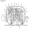
- FIG. 3 is a view of an embodiment of a hermetic compressor according to the present invention
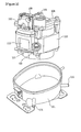
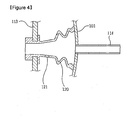
- FIG. 4 is a view of a refrigerant suction noise reduction structure in the embodiment of the hermetic compressor according to the present invention.
- a given lower container 101 and a given upper container are coupled to constitute a hermetic container (hereinafter, indicated by reference numeral 101 of the lower container), and an assembly of a stator 102, a rotor (not shown), a rotational shaft 105, a cylinder block 106, a cylinder 109, a piston (not shown), a valve device (not shown), a head cover 112 and a suction muffler 113 is installed in the hermetic container 101.
- the respective components have been publicly known, and thus their detailed description will be omitted.
- a suction pipe 114 guiding refrigerant to be sucked into the hermetic container 101 and a discharge pipe 115 guiding refrigerant to be discharged to the outside of the hermetic container 101 are provided.
- the suction muffler 113 and the suction pipe 114 communicate with each other via a connector 120 formed of a given elastic material.
- the suction muffler 113 includes two covers coupled to each other to define an inner noise space, and a bent pipe accommodated therein.
- the suction muffler 113 not only reduces the noise of suction refrigerant but also prevents heating of the suction refrigerant when it is sucked into the cylinder 109 through the head cover 112.
- the connector 120 is formed of a given rubber material with elasticity.
- One end of the connector 120 is a cylindrical plane portion and the other end thereof is a trumpet-shaped corrugated portion.
- the plane portion of the connector 120 is coupled between the covers of the suction muffler 113 to be engaged therewith and installed to communicate with the bent pipe of the suction muffler 113.
- the corrugated portion of the connector 120 is brought into contact with the inside of the hermetic container 101 to communicate with the suction pipe 114.
- the connector 120 may be bent at a given angle according to the location of an inlet of the suction muffler 113 and the suction pipe 114.
- a hole 121 which enables an inner space of the connector 120 and an inner space of the hermetic container 101 to communicate with each other, is provided in the connector 120.
- An inner pressure of the connector 120 may be equalized with an inner pressure of the hermetic container 101 through the hole 121. Accordingly, in order to equalize the inner pressure of the connector 120 with the inner pressure of the hermetic container 101 within a preset pressure according to the operation conditions, the number and size of the hole 121 and the location of the hole 121 in the connector 120 may be determined in various ways.
- one or more holes 121 are provided in the plane portion of the connector 120 connected to the inlet of the suction muffler 113 so as to be adjacent to the inlet of the suction muffler 113.
- the hole 121 may be provided in the corrugated portion of the connector 120. However, if the hole 121 is positioned in the corrugated portion of the connector 120, since the refrigerant suction pressure is maintained relatively low, the corrugated portion of the connector 120 is closely attached to the inside surface of the hermetic container 101 and folded. This may interrupt fast equalization between the inner pressure of the connector 120 and the inner pressure of the hermetic container 101. Moreover, the inner pressure of the corrugated portion-side of the connector 120 is equalized with the inner pressure of the hermetic container 101, which reduces the adhesion of the corrugated portion of the connector 120 to the inside of the hermetic container 101. This leads to a refrigerant flow loss.
- the refrigerant compressed in the compression space opens a discharge valve (not shown), is discharged into a discharge space of the head cover 112, and is discharged to the outside through the discharge pipe 115 of the hermetic container 101 via a discharge muffler (not shown) and a loop pipe (not shown).
- the hermetic compressor When the hermetic compressor is operated as described above, heat is generated due to the operation of the motor mechanism unit and the motion of the piston. While the inner pressure of the hermetic container 101 is maintained relatively high, the pressure of the refrigerant sucked through the suction pipe 114, the connector 120 and the suction muffler 113 is maintained lower than the inner pressure of the hermetic container 101. However, the pressures are equalized through the hole 121 of the connector 120. That is, the inner pressure of the hermetic container 101 is lowered and the inner pressure of the connector 120 is raised. Therefore, even if the suction pressure is maintained low according to the operation conditions, it can be equalized with the inner pressure of the hermetic container 101. As the suction pressure rises, the refrigerant suction velocity proportional to a difference between the pressure of the compression space and the suction pressure is reduced. However, the refrigerant suction noise of specific frequency bands can be reduced.
- FIG. 5 is a graph of the noise and the refrigerant velocity in the embodiment of the hermetic compressor according to the present invention.
- the refrigerant suction velocity is 8 m/sec 2 , which is slightly lower than 9 m/sec 2 of the conventional hermetic compressor, but the refrigerant noise in specific frequency bands such as 4 k is about 18 dBA, which is much lower than about 28 dBA of the conventional hermetic compressor. It is apparent that noise performance is improved.
Landscapes
- Engineering & Computer Science (AREA)
- Mechanical Engineering (AREA)
- General Engineering & Computer Science (AREA)
- Physics & Mathematics (AREA)
- Thermal Sciences (AREA)
- Compressor (AREA)
Applications Claiming Priority (2)
| Application Number | Priority Date | Filing Date | Title |
|---|---|---|---|
| KR1020090005244A KR101459163B1 (ko) | 2009-01-21 | 2009-01-21 | 밀폐형 압축기 |
| PCT/KR2009/007164 WO2010085041A2 (ko) | 2009-01-21 | 2009-12-02 | 밀폐형 압축기 |
Publications (3)
| Publication Number | Publication Date |
|---|---|
| EP2381106A2 true EP2381106A2 (de) | 2011-10-26 |
| EP2381106A4 EP2381106A4 (de) | 2012-06-06 |
| EP2381106B1 EP2381106B1 (de) | 2013-06-26 |
Family
ID=42356287
Family Applications (1)
| Application Number | Title | Priority Date | Filing Date |
|---|---|---|---|
| EP09838928.1A Active EP2381106B1 (de) | 2009-01-21 | 2009-12-02 | Hermetischer verdichter |
Country Status (6)
| Country | Link |
|---|---|
| US (1) | US8585373B2 (de) |
| EP (1) | EP2381106B1 (de) |
| KR (1) | KR101459163B1 (de) |
| CN (1) | CN102292547B (de) |
| ES (1) | ES2420983T3 (de) |
| WO (1) | WO2010085041A2 (de) |
Cited By (1)
| Publication number | Priority date | Publication date | Assignee | Title |
|---|---|---|---|---|
| WO2016120446A1 (en) * | 2015-01-30 | 2016-08-04 | Arcelik Anonim Sirketi | A compressor |
Families Citing this family (2)
| Publication number | Priority date | Publication date | Assignee | Title |
|---|---|---|---|---|
| BR102014029659B1 (pt) * | 2014-11-27 | 2022-01-11 | Embraco Indústria De Compressores E Soluções Em Refrigeração Ltda | Filtro acústico de sucção e linha de sucção incluindo filtro acústico de sucção |
| KR102156576B1 (ko) | 2015-02-04 | 2020-09-16 | 엘지전자 주식회사 | 왕복동식 압축기 |
Family Cites Families (8)
| Publication number | Priority date | Publication date | Assignee | Title |
|---|---|---|---|---|
| IT1179810B (it) * | 1984-10-31 | 1987-09-16 | Aspera Spa | Gruppo motocompressore ermetico per circuiti frigoriferi |
| IT1184167B (it) | 1985-03-21 | 1987-10-22 | Eurodomestici Ind Riunite | Perfezionamento nei motocompressori sigillati per circuiti frigoriferi |
| KR100207792B1 (ko) * | 1997-02-24 | 1999-07-15 | 윤종용 | 밀폐형 압축기 |
| CN1131376C (zh) * | 1998-12-31 | 2003-12-17 | Lg电子株式会社 | 密闭式压缩机吸入消声器的安装结构 |
| WO2006109239A1 (en) * | 2005-04-12 | 2006-10-19 | Arcelik Anonim Sirketi | A compressor |
| ES2339053T3 (es) * | 2005-08-04 | 2010-05-14 | Arcelik Anonim Sirketi | Compresor. |
| KR100677518B1 (ko) * | 2006-03-10 | 2007-02-02 | 엘지전자 주식회사 | 압축기의 머플러 가스흡입 안내장치 |
| KR20080000996A (ko) * | 2006-06-28 | 2008-01-03 | 삼성광주전자 주식회사 | 밀폐형 압축기 |
-
2009
- 2009-01-21 KR KR1020090005244A patent/KR101459163B1/ko active Active
- 2009-12-02 EP EP09838928.1A patent/EP2381106B1/de active Active
- 2009-12-02 CN CN200980155189.9A patent/CN102292547B/zh active Active
- 2009-12-02 ES ES09838928T patent/ES2420983T3/es active Active
- 2009-12-02 US US13/145,327 patent/US8585373B2/en active Active
- 2009-12-02 WO PCT/KR2009/007164 patent/WO2010085041A2/ko not_active Ceased
Non-Patent Citations (2)
| Title |
|---|
| No further relevant documents disclosed * |
| See also references of WO2010085041A2 * |
Cited By (1)
| Publication number | Priority date | Publication date | Assignee | Title |
|---|---|---|---|---|
| WO2016120446A1 (en) * | 2015-01-30 | 2016-08-04 | Arcelik Anonim Sirketi | A compressor |
Also Published As
| Publication number | Publication date |
|---|---|
| EP2381106A4 (de) | 2012-06-06 |
| WO2010085041A2 (ko) | 2010-07-29 |
| KR101459163B1 (ko) | 2014-11-07 |
| EP2381106B1 (de) | 2013-06-26 |
| KR20100085779A (ko) | 2010-07-29 |
| CN102292547B (zh) | 2014-06-18 |
| US20110280743A1 (en) | 2011-11-17 |
| ES2420983T3 (es) | 2013-08-28 |
| WO2010085041A3 (ko) | 2010-12-02 |
| US8585373B2 (en) | 2013-11-19 |
| CN102292547A (zh) | 2011-12-21 |
Similar Documents
| Publication | Publication Date | Title |
|---|---|---|
| EP3657018B1 (de) | Spiralverdichter | |
| US10233930B2 (en) | Rotary compressor having two cylinders | |
| EP2407669B1 (de) | Verdichter mit Ansaug- und Austrittsleitungen | |
| WO2008133445A1 (en) | Compressor and oil supplying structure therefor | |
| EP4170166B1 (de) | Verdichtergehäuse für einen kältemittelverdichter | |
| KR100723104B1 (ko) | 밀폐형 압축기 | |
| KR102156576B1 (ko) | 왕복동식 압축기 | |
| US10781805B2 (en) | Small air compressor | |
| EP2891801A2 (de) | Verdichter- und Ventilanordnung davon zur Verringerung von Pulsationen und/oder Geräuschen | |
| EP2381106A2 (de) | Hermetischer verdichter | |
| CN110500259A (zh) | 线性压缩机 | |
| KR20200034454A (ko) | 압축기 및 이를 이용한 전자기기 | |
| CN214403986U (zh) | 一种油路结构、卧式涡旋压缩机及冷冻设备 | |
| EP2685106B1 (de) | Zweistufiger Kompressor und zweistufiges Kompressionssystem | |
| KR101870180B1 (ko) | 2단 로터리 압축기 | |
| KR101189916B1 (ko) | 압축기 | |
| KR102122792B1 (ko) | 압축기용 가스켓 | |
| KR100788423B1 (ko) | 흡입머플러 및 이를 갖는 압축기 | |
| EP2010786A1 (de) | Hermetischer verdichter | |
| KR100314037B1 (ko) | 압축기의 흡입가스 가열방지구조 | |
| KR100746425B1 (ko) | 리니어 압축기의 오일 공급 유닛 | |
| KR101457706B1 (ko) | 밀폐형 압축기 | |
| KR101679079B1 (ko) | 압축기 | |
| CN1455104A (zh) | 密闭性压缩机的工作液体吸入装置 | |
| KR101698085B1 (ko) | 밀폐형 압축기 |
Legal Events
| Date | Code | Title | Description |
|---|---|---|---|
| PUAI | Public reference made under article 153(3) epc to a published international application that has entered the european phase |
Free format text: ORIGINAL CODE: 0009012 |
|
| 17P | Request for examination filed |
Effective date: 20110722 |
|
| AK | Designated contracting states |
Kind code of ref document: A2 Designated state(s): AT BE BG CH CY CZ DE DK EE ES FI FR GB GR HR HU IE IS IT LI LT LU LV MC MK MT NL NO PL PT RO SE SI SK SM TR |
|
| DAX | Request for extension of the european patent (deleted) | ||
| A4 | Supplementary search report drawn up and despatched |
Effective date: 20120507 |
|
| RIC1 | Information provided on ipc code assigned before grant |
Ipc: F04B 39/10 20060101ALI20120427BHEP Ipc: F04B 39/12 20060101AFI20120427BHEP Ipc: F04B 39/00 20060101ALI20120427BHEP |
|
| GRAP | Despatch of communication of intention to grant a patent |
Free format text: ORIGINAL CODE: EPIDOSNIGR1 |
|
| GRAS | Grant fee paid |
Free format text: ORIGINAL CODE: EPIDOSNIGR3 |
|
| GRAA | (expected) grant |
Free format text: ORIGINAL CODE: 0009210 |
|
| AK | Designated contracting states |
Kind code of ref document: B1 Designated state(s): AT BE BG CH CY CZ DE DK EE ES FI FR GB GR HR HU IE IS IT LI LT LU LV MC MK MT NL NO PL PT RO SE SI SK SM TR |
|
| REG | Reference to a national code |
Ref country code: GB Ref legal event code: FG4D |
|
| REG | Reference to a national code |
Ref country code: CH Ref legal event code: EP |
|
| REG | Reference to a national code |
Ref country code: AT Ref legal event code: REF Ref document number: 618812 Country of ref document: AT Kind code of ref document: T Effective date: 20130715 |
|
| REG | Reference to a national code |
Ref country code: IE Ref legal event code: FG4D |
|
| REG | Reference to a national code |
Ref country code: DE Ref legal event code: R096 Ref document number: 602009016759 Country of ref document: DE Effective date: 20130822 |
|
| REG | Reference to a national code |
Ref country code: ES Ref legal event code: FG2A Ref document number: 2420983 Country of ref document: ES Kind code of ref document: T3 Effective date: 20130828 |
|
| PG25 | Lapsed in a contracting state [announced via postgrant information from national office to epo] |
Ref country code: LT Free format text: LAPSE BECAUSE OF FAILURE TO SUBMIT A TRANSLATION OF THE DESCRIPTION OR TO PAY THE FEE WITHIN THE PRESCRIBED TIME-LIMIT Effective date: 20130626 Ref country code: GR Free format text: LAPSE BECAUSE OF FAILURE TO SUBMIT A TRANSLATION OF THE DESCRIPTION OR TO PAY THE FEE WITHIN THE PRESCRIBED TIME-LIMIT Effective date: 20130927 Ref country code: SE Free format text: LAPSE BECAUSE OF FAILURE TO SUBMIT A TRANSLATION OF THE DESCRIPTION OR TO PAY THE FEE WITHIN THE PRESCRIBED TIME-LIMIT Effective date: 20130626 Ref country code: SI Free format text: LAPSE BECAUSE OF FAILURE TO SUBMIT A TRANSLATION OF THE DESCRIPTION OR TO PAY THE FEE WITHIN THE PRESCRIBED TIME-LIMIT Effective date: 20130626 Ref country code: NO Free format text: LAPSE BECAUSE OF FAILURE TO SUBMIT A TRANSLATION OF THE DESCRIPTION OR TO PAY THE FEE WITHIN THE PRESCRIBED TIME-LIMIT Effective date: 20130926 Ref country code: FI Free format text: LAPSE BECAUSE OF FAILURE TO SUBMIT A TRANSLATION OF THE DESCRIPTION OR TO PAY THE FEE WITHIN THE PRESCRIBED TIME-LIMIT Effective date: 20130626 |
|
| REG | Reference to a national code |
Ref country code: AT Ref legal event code: MK05 Ref document number: 618812 Country of ref document: AT Kind code of ref document: T Effective date: 20130626 |
|
| REG | Reference to a national code |
Ref country code: LT Ref legal event code: MG4D |
|
| PG25 | Lapsed in a contracting state [announced via postgrant information from national office to epo] |
Ref country code: HR Free format text: LAPSE BECAUSE OF FAILURE TO SUBMIT A TRANSLATION OF THE DESCRIPTION OR TO PAY THE FEE WITHIN THE PRESCRIBED TIME-LIMIT Effective date: 20130626 Ref country code: BG Free format text: LAPSE BECAUSE OF FAILURE TO SUBMIT A TRANSLATION OF THE DESCRIPTION OR TO PAY THE FEE WITHIN THE PRESCRIBED TIME-LIMIT Effective date: 20130926 |
|
| REG | Reference to a national code |
Ref country code: NL Ref legal event code: VDEP Effective date: 20130626 |
|
| PG25 | Lapsed in a contracting state [announced via postgrant information from national office to epo] |
Ref country code: LV Free format text: LAPSE BECAUSE OF FAILURE TO SUBMIT A TRANSLATION OF THE DESCRIPTION OR TO PAY THE FEE WITHIN THE PRESCRIBED TIME-LIMIT Effective date: 20130626 |
|
| PG25 | Lapsed in a contracting state [announced via postgrant information from national office to epo] |
Ref country code: SK Free format text: LAPSE BECAUSE OF FAILURE TO SUBMIT A TRANSLATION OF THE DESCRIPTION OR TO PAY THE FEE WITHIN THE PRESCRIBED TIME-LIMIT Effective date: 20130626 Ref country code: AT Free format text: LAPSE BECAUSE OF FAILURE TO SUBMIT A TRANSLATION OF THE DESCRIPTION OR TO PAY THE FEE WITHIN THE PRESCRIBED TIME-LIMIT Effective date: 20130626 Ref country code: CY Free format text: LAPSE BECAUSE OF FAILURE TO SUBMIT A TRANSLATION OF THE DESCRIPTION OR TO PAY THE FEE WITHIN THE PRESCRIBED TIME-LIMIT Effective date: 20130724 Ref country code: EE Free format text: LAPSE BECAUSE OF FAILURE TO SUBMIT A TRANSLATION OF THE DESCRIPTION OR TO PAY THE FEE WITHIN THE PRESCRIBED TIME-LIMIT Effective date: 20130626 Ref country code: CZ Free format text: LAPSE BECAUSE OF FAILURE TO SUBMIT A TRANSLATION OF THE DESCRIPTION OR TO PAY THE FEE WITHIN THE PRESCRIBED TIME-LIMIT Effective date: 20130626 Ref country code: IS Free format text: LAPSE BECAUSE OF FAILURE TO SUBMIT A TRANSLATION OF THE DESCRIPTION OR TO PAY THE FEE WITHIN THE PRESCRIBED TIME-LIMIT Effective date: 20131026 Ref country code: BE Free format text: LAPSE BECAUSE OF FAILURE TO SUBMIT A TRANSLATION OF THE DESCRIPTION OR TO PAY THE FEE WITHIN THE PRESCRIBED TIME-LIMIT Effective date: 20130626 Ref country code: PT Free format text: LAPSE BECAUSE OF FAILURE TO SUBMIT A TRANSLATION OF THE DESCRIPTION OR TO PAY THE FEE WITHIN THE PRESCRIBED TIME-LIMIT Effective date: 20131028 |
|
| PG25 | Lapsed in a contracting state [announced via postgrant information from national office to epo] |
Ref country code: RO Free format text: LAPSE BECAUSE OF FAILURE TO SUBMIT A TRANSLATION OF THE DESCRIPTION OR TO PAY THE FEE WITHIN THE PRESCRIBED TIME-LIMIT Effective date: 20130626 Ref country code: NL Free format text: LAPSE BECAUSE OF FAILURE TO SUBMIT A TRANSLATION OF THE DESCRIPTION OR TO PAY THE FEE WITHIN THE PRESCRIBED TIME-LIMIT Effective date: 20130626 Ref country code: PL Free format text: LAPSE BECAUSE OF FAILURE TO SUBMIT A TRANSLATION OF THE DESCRIPTION OR TO PAY THE FEE WITHIN THE PRESCRIBED TIME-LIMIT Effective date: 20130626 |
|
| PG25 | Lapsed in a contracting state [announced via postgrant information from national office to epo] |
Ref country code: CY Free format text: LAPSE BECAUSE OF FAILURE TO SUBMIT A TRANSLATION OF THE DESCRIPTION OR TO PAY THE FEE WITHIN THE PRESCRIBED TIME-LIMIT Effective date: 20130626 |
|
| PG25 | Lapsed in a contracting state [announced via postgrant information from national office to epo] |
Ref country code: DK Free format text: LAPSE BECAUSE OF FAILURE TO SUBMIT A TRANSLATION OF THE DESCRIPTION OR TO PAY THE FEE WITHIN THE PRESCRIBED TIME-LIMIT Effective date: 20130626 |
|
| PLBE | No opposition filed within time limit |
Free format text: ORIGINAL CODE: 0009261 |
|
| STAA | Information on the status of an ep patent application or granted ep patent |
Free format text: STATUS: NO OPPOSITION FILED WITHIN TIME LIMIT |
|
| 26N | No opposition filed |
Effective date: 20140327 |
|
| REG | Reference to a national code |
Ref country code: DE Ref legal event code: R097 Ref document number: 602009016759 Country of ref document: DE Effective date: 20140327 |
|
| REG | Reference to a national code |
Ref country code: CH Ref legal event code: PL |
|
| GBPC | Gb: european patent ceased through non-payment of renewal fee |
Effective date: 20131202 |
|
| PG25 | Lapsed in a contracting state [announced via postgrant information from national office to epo] |
Ref country code: LU Free format text: LAPSE BECAUSE OF FAILURE TO SUBMIT A TRANSLATION OF THE DESCRIPTION OR TO PAY THE FEE WITHIN THE PRESCRIBED TIME-LIMIT Effective date: 20131202 |
|
| REG | Reference to a national code |
Ref country code: IE Ref legal event code: MM4A |
|
| REG | Reference to a national code |
Ref country code: FR Ref legal event code: ST Effective date: 20140829 |
|
| PG25 | Lapsed in a contracting state [announced via postgrant information from national office to epo] |
Ref country code: IE Free format text: LAPSE BECAUSE OF NON-PAYMENT OF DUE FEES Effective date: 20131202 Ref country code: CH Free format text: LAPSE BECAUSE OF NON-PAYMENT OF DUE FEES Effective date: 20131231 Ref country code: LI Free format text: LAPSE BECAUSE OF NON-PAYMENT OF DUE FEES Effective date: 20131231 |
|
| PG25 | Lapsed in a contracting state [announced via postgrant information from national office to epo] |
Ref country code: FR Free format text: LAPSE BECAUSE OF NON-PAYMENT OF DUE FEES Effective date: 20131231 Ref country code: GB Free format text: LAPSE BECAUSE OF NON-PAYMENT OF DUE FEES Effective date: 20131202 |
|
| PG25 | Lapsed in a contracting state [announced via postgrant information from national office to epo] |
Ref country code: MC Free format text: LAPSE BECAUSE OF FAILURE TO SUBMIT A TRANSLATION OF THE DESCRIPTION OR TO PAY THE FEE WITHIN THE PRESCRIBED TIME-LIMIT Effective date: 20130626 |
|
| PG25 | Lapsed in a contracting state [announced via postgrant information from national office to epo] |
Ref country code: SM Free format text: LAPSE BECAUSE OF FAILURE TO SUBMIT A TRANSLATION OF THE DESCRIPTION OR TO PAY THE FEE WITHIN THE PRESCRIBED TIME-LIMIT Effective date: 20130626 |
|
| PG25 | Lapsed in a contracting state [announced via postgrant information from national office to epo] |
Ref country code: TR Free format text: LAPSE BECAUSE OF FAILURE TO SUBMIT A TRANSLATION OF THE DESCRIPTION OR TO PAY THE FEE WITHIN THE PRESCRIBED TIME-LIMIT Effective date: 20130626 |
|
| PG25 | Lapsed in a contracting state [announced via postgrant information from national office to epo] |
Ref country code: MK Free format text: LAPSE BECAUSE OF FAILURE TO SUBMIT A TRANSLATION OF THE DESCRIPTION OR TO PAY THE FEE WITHIN THE PRESCRIBED TIME-LIMIT Effective date: 20130626 Ref country code: HU Free format text: LAPSE BECAUSE OF FAILURE TO SUBMIT A TRANSLATION OF THE DESCRIPTION OR TO PAY THE FEE WITHIN THE PRESCRIBED TIME-LIMIT; INVALID AB INITIO Effective date: 20091202 |
|
| PG25 | Lapsed in a contracting state [announced via postgrant information from national office to epo] |
Ref country code: MT Free format text: LAPSE BECAUSE OF FAILURE TO SUBMIT A TRANSLATION OF THE DESCRIPTION OR TO PAY THE FEE WITHIN THE PRESCRIBED TIME-LIMIT Effective date: 20130626 |
|
| PGFP | Annual fee paid to national office [announced via postgrant information from national office to epo] |
Ref country code: ES Payment date: 20200113 Year of fee payment: 11 |
|
| REG | Reference to a national code |
Ref country code: ES Ref legal event code: FD2A Effective date: 20220207 |
|
| PG25 | Lapsed in a contracting state [announced via postgrant information from national office to epo] |
Ref country code: ES Free format text: LAPSE BECAUSE OF NON-PAYMENT OF DUE FEES Effective date: 20201203 |
|
| PGFP | Annual fee paid to national office [announced via postgrant information from national office to epo] |
Ref country code: DE Payment date: 20251105 Year of fee payment: 17 |
|
| PGFP | Annual fee paid to national office [announced via postgrant information from national office to epo] |
Ref country code: IT Payment date: 20251106 Year of fee payment: 17 |