EP2382930A1 - Werkzeug zum Erzeugen einer Knochenaussparung, und chirurgisches Kit mit mehreren Formwerkzeugen - Google Patents
Werkzeug zum Erzeugen einer Knochenaussparung, und chirurgisches Kit mit mehreren Formwerkzeugen Download PDFInfo
- Publication number
- EP2382930A1 EP2382930A1 EP11163954A EP11163954A EP2382930A1 EP 2382930 A1 EP2382930 A1 EP 2382930A1 EP 11163954 A EP11163954 A EP 11163954A EP 11163954 A EP11163954 A EP 11163954A EP 2382930 A1 EP2382930 A1 EP 2382930A1
- Authority
- EP
- European Patent Office
- Prior art keywords
- implant
- tool
- recess
- test
- diameter
- Prior art date
- Legal status (The legal status is an assumption and is not a legal conclusion. Google has not performed a legal analysis and makes no representation as to the accuracy of the status listed.)
- Withdrawn
Links
Images



Classifications
-
- A—HUMAN NECESSITIES
- A61—MEDICAL OR VETERINARY SCIENCE; HYGIENE
- A61F—FILTERS IMPLANTABLE INTO BLOOD VESSELS; PROSTHESES; DEVICES PROVIDING PATENCY TO, OR PREVENTING COLLAPSING OF, TUBULAR STRUCTURES OF THE BODY, e.g. STENTS; ORTHOPAEDIC, NURSING OR CONTRACEPTIVE DEVICES; FOMENTATION; TREATMENT OR PROTECTION OF EYES OR EARS; BANDAGES, DRESSINGS OR ABSORBENT PADS; FIRST-AID KITS
- A61F2/00—Filters implantable into blood vessels; Prostheses, i.e. artificial substitutes or replacements for parts of the body; Appliances for connecting them with the body; Devices providing patency to, or preventing collapsing of, tubular structures of the body, e.g. stents
- A61F2/02—Prostheses implantable into the body
- A61F2/30—Joints
- A61F2/46—Special tools for implanting artificial joints
- A61F2/4684—Trial or dummy prostheses
-
- A—HUMAN NECESSITIES
- A61—MEDICAL OR VETERINARY SCIENCE; HYGIENE
- A61B—DIAGNOSIS; SURGERY; IDENTIFICATION
- A61B17/00—Surgical instruments, devices or methods
- A61B17/16—Instruments for performing osteoclasis; Drills or chisels for bones; Trepans
- A61B17/1662—Instruments for performing osteoclasis; Drills or chisels for bones; Trepans for particular parts of the body
- A61B17/1684—Instruments for performing osteoclasis; Drills or chisels for bones; Trepans for particular parts of the body for the shoulder
-
- A—HUMAN NECESSITIES
- A61—MEDICAL OR VETERINARY SCIENCE; HYGIENE
- A61B—DIAGNOSIS; SURGERY; IDENTIFICATION
- A61B17/00—Surgical instruments, devices or methods
- A61B17/16—Instruments for performing osteoclasis; Drills or chisels for bones; Trepans
- A61B17/1613—Component parts
- A61B17/1615—Drill bits, i.e. rotating tools extending from a handpiece to contact the worked material
-
- A—HUMAN NECESSITIES
- A61—MEDICAL OR VETERINARY SCIENCE; HYGIENE
- A61B—DIAGNOSIS; SURGERY; IDENTIFICATION
- A61B17/00—Surgical instruments, devices or methods
- A61B17/56—Surgical instruments or methods for treatment of bones or joints; Devices specially adapted therefor
- A61B17/58—Surgical instruments or methods for treatment of bones or joints; Devices specially adapted therefor for osteosynthesis, e.g. bone plates, screws or setting implements
- A61B17/88—Osteosynthesis instruments; Methods or means for implanting or extracting internal or external fixation devices
- A61B17/885—Tools for expanding or compacting bones or discs or cavities therein
-
- A—HUMAN NECESSITIES
- A61—MEDICAL OR VETERINARY SCIENCE; HYGIENE
- A61B—DIAGNOSIS; SURGERY; IDENTIFICATION
- A61B90/00—Instruments, implements or accessories specially adapted for surgery or diagnosis and not covered by any of the groups A61B1/00 - A61B50/00, e.g. for luxation treatment or for protecting wound edges
- A61B90/90—Identification means for patients or instruments, e.g. tags
- A61B90/92—Identification means for patients or instruments, e.g. tags coded with colour
-
- A—HUMAN NECESSITIES
- A61—MEDICAL OR VETERINARY SCIENCE; HYGIENE
- A61F—FILTERS IMPLANTABLE INTO BLOOD VESSELS; PROSTHESES; DEVICES PROVIDING PATENCY TO, OR PREVENTING COLLAPSING OF, TUBULAR STRUCTURES OF THE BODY, e.g. STENTS; ORTHOPAEDIC, NURSING OR CONTRACEPTIVE DEVICES; FOMENTATION; TREATMENT OR PROTECTION OF EYES OR EARS; BANDAGES, DRESSINGS OR ABSORBENT PADS; FIRST-AID KITS
- A61F2/00—Filters implantable into blood vessels; Prostheses, i.e. artificial substitutes or replacements for parts of the body; Appliances for connecting them with the body; Devices providing patency to, or preventing collapsing of, tubular structures of the body, e.g. stents
- A61F2/02—Prostheses implantable into the body
- A61F2/30—Joints
- A61F2/40—Joints for shoulders
- A61F2/4014—Humeral heads or necks; Connections of endoprosthetic heads or necks to endoprosthetic humeral shafts
-
- A—HUMAN NECESSITIES
- A61—MEDICAL OR VETERINARY SCIENCE; HYGIENE
- A61B—DIAGNOSIS; SURGERY; IDENTIFICATION
- A61B90/00—Instruments, implements or accessories specially adapted for surgery or diagnosis and not covered by any of the groups A61B1/00 - A61B50/00, e.g. for luxation treatment or for protecting wound edges
- A61B90/06—Measuring instruments not otherwise provided for
- A61B2090/062—Measuring instruments not otherwise provided for penetration depth
-
- A—HUMAN NECESSITIES
- A61—MEDICAL OR VETERINARY SCIENCE; HYGIENE
- A61F—FILTERS IMPLANTABLE INTO BLOOD VESSELS; PROSTHESES; DEVICES PROVIDING PATENCY TO, OR PREVENTING COLLAPSING OF, TUBULAR STRUCTURES OF THE BODY, e.g. STENTS; ORTHOPAEDIC, NURSING OR CONTRACEPTIVE DEVICES; FOMENTATION; TREATMENT OR PROTECTION OF EYES OR EARS; BANDAGES, DRESSINGS OR ABSORBENT PADS; FIRST-AID KITS
- A61F2/00—Filters implantable into blood vessels; Prostheses, i.e. artificial substitutes or replacements for parts of the body; Appliances for connecting them with the body; Devices providing patency to, or preventing collapsing of, tubular structures of the body, e.g. stents
- A61F2/02—Prostheses implantable into the body
- A61F2/30—Joints
- A61F2002/30001—Additional features of subject-matter classified in A61F2/28, A61F2/30 and subgroups thereof
- A61F2002/30316—The prosthesis having different structural features at different locations within the same prosthesis; Connections between prosthetic parts; Special structural features of bone or joint prostheses not otherwise provided for
- A61F2002/30535—Special structural features of bone or joint prostheses not otherwise provided for
- A61F2002/30604—Special structural features of bone or joint prostheses not otherwise provided for modular
- A61F2002/30616—Sets comprising a plurality of prosthetic parts of different sizes or orientations
Definitions
- interpositional arthroplasty One type of method used to replace damaged joints (e.g., shoulder joints) is interpositional arthroplasty.
- the method of interpositional arthroplasty uses tissue from the patient or an artificial replacement to repair a damaged or malformed joint.
- An interpositional implant is positioned at the joint to act as an engagement surface between two adjacent bone structures to allow articular movement.
- the present specification describes a method of implanting a prosthesis to repair a joint.
- the method includes displacing a first bone from the joint formed by an intersection between the first bone and a second bone. An end portion of the first bone is resected to define a resected end. A concavity is formed into the resected end using a shaping tool. The bone is compacted to form a support layer lining the concavity.
- the prosthesis is implanted in the concavity against the support layer without attaching the prosthesis to the support layer, the prosthesis including a first surface and a second surface opposite the first surface, each of the first and second surfaces being substantially convex in shape.
- the joint is reformed with the prosthesis such that the prosthesis remains unattached to the support layer and the first and second bones articulate about the prosthesis.
- US-A-6 027 503 describes a reaming member including a distal apical region in the form of a partial sphere having an arc of less than 180° and a proximal cylindrical region.
- the reaming member is not adapted to form fully hemispherical recesses into bones.
- the present invention relates to a bone recess forming tool as defined by claim 1.
- the tool includes a forming head having a forming surface adapted to form a recess into a bone, wherein the forming surface extends through at least a hemispherical dome.
- the forming surface defines a convex hemispherical portion and an upswept portion extending beyond the convex hemispherical portion.
- the present invention further relates to a surgical kit of parts for implanting joint prostheses available in a plurality of graduating diameters, as defined by claim 11.
- the kit includes a plurality of test prostheses each graduating in diameter such that each one of the test prostheses has a diameter corresponding to one of the available graduating diameters of the joint prosthesis.
- the kit also includes a plurality of reamers each graduating in diameter such that each one of the reamers has a diameter corresponding to one of the available graduating diameters of the joint prosthesis.
- the kit also includes a plurality of compactors each graduating in diameter such that each one of the compactors has a diameter corresponding to one of the available graduating diameters of the joint prosthesis.
- each one of the test prostheses, reamers, and compactors has the same diameter forms an operational tool set for implanting a joint prosthesis of the same diameter.
- the reamers and/or the compactors are according to the aforementioned bone recess forming tool.
- each of the test prostheses, reamers, and compactors include colored indicia indicating to which operational tool set a particular test prosthetic, reamer, and compactor belongs.
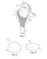
- FIG. 1 shows a joint system, according to some embodiments.
- FIG. 2 shows an interpositional implant, according to some embodiments.
- FIG. 3 shows another interpositional implant, according to some embodiments.
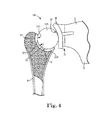
- FIG. 4 shows another joint system, according to some embodiments.
- FIG. 5 shows a surgical kit, according to some embodiments.
- FIG. 6 shows a reamer of the surgical kit of FIG. 5 , according to some embodiments.
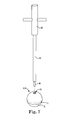
- FIG. 7 shows a test implant and handle of the surgical kit of FIG. 5 , according to some embodiments.
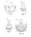
- FIG. 8 shows a starter compactor of the kit of FIG. 5 , according to some embodiments.
- FIG. 9 shows an initial compactor of the kit of FIG. 5 , according to some embodiments.
- FIG. 10 shows a final compactor of the kit of FIG. 5 , according to some embodiments.
- FIGS. 11 - 14 are illustrative of a method of implanting and forming the joint system of FIG. 1 , according to some embodiments.
- FIG. 1 is a schematic view of a joint system 10 (e.g., a glenohumeral joint system) including an interpositional implant 12, a first boney structure, or bone (e.g., a humerus H) and a second boney structure, or bone (e.g., a glenoid G), where the first and second boney structures articulate about the interpositional implant 12.
- the interpositional implant 12 is interposed between the two boney structures - the humerus H and the glenoid G - to help repair joint function.
- the implant 12 is primarily discussed as being implanted in a human patient's shoulder, the implant 12 may also be modified and implanted in other locations.
- the implant 12 is optionally modified to be implanted between a variety of boney structures in a hip, ankle, hand, foot, or other joint, for example, whether human or other animal.
- the interpositional implant 12 also described as an interpositional prosthesis, is formed as a single piece, or monolithic unit, and includes at least two convex surfaces, although implants formed of separate, connected parts are contemplated.
- the implant 12 includes a convex first surface 18 and a convex second surface 20 opposed to the first surface 18, though the interpositional implant 12 is optionally non-spherical and the surfaces 18, 20 optionally have different radii of curvature from one other.
- the first surface 18 is in direct contact with the glenoid G, and in particular the glenoid cavity, and the second surface 20 is in direct contact with a portion of the humerus H.
- the implant 12 generally defines an midline M between the first and second convex surfaces 18, 20.
- FIG. 1 shows a generally spherical, or spheroid shape for the interpositional implant 12
- FIG. 2 shows an interpositional implant 12A having an upper, spheroid portion above a midline M A and a lower, spherical portion below the midline M A having a different radius of curvature.
- FIG. 3 shows an interpositional implant 12B having a more symmetrical spheroid shape (e.g., a prolate spheroid shape) above and below a midline M B .
- the convexities of the first and/or second surfaces 18, 20 are complex, including multiple radii, including the shapes described in U.S. Patent Application Publication 2007/0225818, filed March 21, 2007 , and titled "Non-Spherical Articulating Surfaces in Shoulder and Hip Replacement".
- the implant 12 has been described, a variety of shapes are contemplated, such as an egg-shaped implant, for example.
- the interpositional implant 12 defines the midline M in an antero-posterior plane and a height perpendicular to the midline M, for example in a superoinferior plane).
- the diameter of the sphere corresponds to both the width of the implant 12 along the midline M and the maximum effective height of the sphere perpendicular to the midline M.
- the implant 12 is formed of an outer layer of pyrocarbon, or pyrolytic carbon, over a graphite substrate or is formed substantially entirely of pyrocarbon, for example.
- the interpositional implant 12 is characterized by a Young's Modulus of from about 10 GPa to about 35 GPa, for example, or from about 21 to about 28 GPa, for example, which is relatively low compared to the much higher Young's modulus of titanium implants.
- the interpositional implant 12 is optionally hollow or otherwise defines an internal void V as indicated in FIG. 1 by a broken circle.
- the void V optionally takes a variety of shapes and forms, including multiple voids (e.g., a plurality of larger voids or a plurality of smaller voids similar to a sponge structure) or other forms.
- the weight of the implant 12 is optionally reduced and/or other properties of the implant 12 are adjusted as desired.
- the humeral head of the humerus H is removed, or resected, proximate the anatomical neck AN, where the humerus H defines a proximal humerus PH.
- the humerus defines a recess 22 that is substantially concave in shape, extending at least through a full hemispherical arc, although other shapes are also contemplated.
- the recess 22, also described as a concavity or a pocket, has an articulation surface 24, or reinforcement bed, that lines the recess 22 which, as described in greater detail below, is optionally formed via compacting and/or reaming methodology.
- the articulation surface 24 forms a reinforced bed, or liner, for contacting the interpositional implant 12.
- the recess 22 is formed into epiphyseal/metaphyseal bone of the humerus H and optionally extends into the diaphysis in some embodiments, though typically preferential to limit the recess 22 to the metaphyseal bone.
- a plug or plugs e.g., made of bone from the humeral head (not shown) or other bone material
- the articulation surface 24 is formed of cortical or cortical-like bone C that forms over time following surgical insertion of the interpositional implant 12.
- the depth of the recess 22 is measured or otherwise evaluated from the bottom of the recess 22 to a plane of the resected end of the humerus H, although other reference planes are employed as appropriate.
- the interpositional implant 12 is not cemented, adhered, or otherwise fixed to the articulation surface 24, leaving the interpositional implant 12 free to rotate in the recess 22. In some embodiments, however, there is some frictional engagement between the recess and the interpositional implant 12 - for example, in association with press fitting the interpositional implant 12 into the recess 22 and/or following growth of the humerus H.
- the glenoid G defines an articulation surface 28 and, in some embodiments, the articulation surface 28 corresponds to the natural glenoid cavity where no or very little surface modification is made to the glenoid cavity during implantation.
- Use of the implant 12 with an unmodified glenoid cavity can be particularly beneficial for partial replacement of a shoulder joint in cases where the rotator cuff is still functional.
- the articulation surface 28 is formed into the scapula S at the glenoid cavity (e.g., using the reaming and/or compacting methodology similar to that used with the humerus H (described in greater detail below) or a glenoid component is attached to the glenoid G for interacting with the implant 12 as shown in FIG. 4 .
- the interpositional implant 12 optionally interacts directly with an articulation surface 28 of the glenoid G, e.g., without any intermediate components between the interpositional implant 12 and the glenoid cavity.
- the interpositional implant 12 also interacts directly with the articulation surface 24, which is formed in the humerus H according to some methods of preparing the humerus H for receiving the interpositional implant 12.
- a joint system 10A further includes one or both of a glenoid component 30 (e.g., implanted in a scapula S of the glenoid G) and/or a humeral component 32, such as those described in U.S. Patent Application Publication 2009/0287309 (“the '309 Publication”), filed December 17, 2008, and titled "Intra-Articular Joint Replacement”.
- a glenoid component 30 e.g., implanted in a scapula S of the glenoid G
- a humeral component 32 such as those described in U.S. Patent Application Publication 2009/0287309 (“the '309 Publication”), filed December 17, 2008, and titled "Intra-Articular Joint Replacement”.
- the glenoid component 30 includes an articular member 36 with a generally concave articular surface 38 that engages interpositional implant 12A, where the interpositional implant 12A is optionally substantially similar to the implant 12 and is laterally remote from the resected surface of the glenoid G in the sense that, if the articular member 36 were omitted, the interpositional implant 12A would be directly juxtaposed with the glenoid G (e.g., as is shown in the system 10 of FIG. 1 ).
- the humeral component 32 optionally supplements, or reinforces, a recess 22A in the humerus H, where the recess 22A defines articulation surface 24A substantially similar to articulation surface 24.
- the humeral component 32 optionally includes an articular member 40 with a generally concave surface 42 formed from a resected portion of the humerus H and installed in the recess 22A according to similar methodology to that described in the '309 Publication, for example.
- the interpositional implant 12A is positioned between the articular member 36 of the glenoid component 30 and the articular member 40 of the humeral component 16A - the radius of the interpositional implant 12A being typically equal to or less than the radii of the concave articular surfaces 38, 42.
- FIG. 5 illustrates a surgical kit 50, or kit of parts, used in association with some surgical methods for implanting the interpositional implant 12.
- the kit 50 includes a plurality of reamers 60, a plurality of test implants 62, and a plurality of compactors 64.
- the kit 50 also optionally includes wrenches, pilot hole tips/bits, cleaning tips/bits, and other components as desired.
- the kit 50 is prepackaged as a sterile unit and/or is adapted to be sterilized prior to use (e.g., via autoclave).
- the plurality of reamers 60 are described as forming or shaping tools and are provided in graduating sizes.
- the plurality of reamers 60 are generally indicated for use in preparing the recess 22 in the resected end of the humerus H.
- Each of the plurality of reamers includes a shaft 70 and a cutting head 72.
- one of the plurality of reamers 60 is a starter reamer 74 having a smaller cutting head diameter than the other reamers 60.
- the starter reamer 74 is optionally utilized early in the formation process of the recess 22 in order to form initial cuts into the resected head of the humerus H, for example.
- the starter reamer 74 is cannulated and includes an optional pilot tip (not shown), such as a sharp thin projection inserted into the cannulated reamer and projecting from the reamer tip to guide the reaming process.
- the reamers 60 are optionally adapted to have reaming diameters graduating in size from about 34 mm to about 46 mm (e.g., in 2 mm increments), although a variety of dimensions are contemplated.
- Each shaft 70 is optionally color coded and/or otherwise marked with indicia (e.g., lettering) which, as described in greater detail, indicates whether a particular reamer 60 belongs to a corresponding operational tool set, where the tool sets are generally grouped by size (e.g., corresponding to an expected size for the implant 12 to be placed in the resected head of the humerus H).
- the cutting head 72 of one of the plurality of reamers 60 is shown in FIG. 6 , according to some embodiments.
- Each of the reamers 60 is optionally substantially similar other than differing generally in reaming diameter, and as such the cutting heads of the plurality of reamers 60 are described collectively with reference to the head 72 shown in FIG. 6 .
- the head 72 is generally dome-shaped and includes a plurality of arcuate blades 76, the profiles of which define a cutting or forming surface.
- the head 72 has a substantially convex outer profile such that the head 72 is adapted to cut, or carve a generally concave recess into bone, e.g., into the resected head of the humerus H.
- the convex outer profile of the cutting head 72 extends at least through a full hemispherical arc that defines a reaming diameter of the cutting head 72.
- the head 72 is adapted to cut at least a full hemisphere and optionally includes an extended cutting portion 78 sweeping upward beyond a hemispherical cutting portion 79 of the cutting head 72.
- the head 72 is adapted to form fully hemispherical recesses and recesses deeper than the diameter of cut of the cutting head 72.
- the head 72 includes a plurality of arcuate blades 76 extending on the hemispherical portion 79 and the upswept portion 78.
- the head 72 includes a plurality of arcuate blades 76 extending on the hemispherical portion 79, including the border between the hemispherical portion 79 and the upswept portion 78.
- the extended cutting portion 78 includes one or more demarcation lines RL for indicating one or more selected reaming depths (two are shown in FIG. 6 , though more or less are employed as appropriate).
- a first one of the demarcation lines RL is located approximately at a height corresponding to the transition from the hemispherical cutting portion 79 to the extended cutting portion 78 and a second one of the demarcation lines RL is located a pre-determined height above the first demarcation line RL, although a variety of heights are contemplated.
- the demarcation lines RL are optionally grooves formed into the blades 76 that are adapted or otherwise configured to be viewed by a surgeon during reaming.
- FIG. 7 shows a first test implant 62A of the plurality of test implants 62 along with an associated handle 80 for manipulating the test implants 62.
- each of the test implants 62 is substantially similar other than differing generally in size and color, and as such the test implants 62 are described collectively with reference to the first test implant 62A shown in FIG. 7 .
- the test implants 62 are shown as being substantially similar, it should be understood that test implants of differing shape, material, or other characteristic(s) are also contemplated.
- the first test implant 62A is substantially spherical, or spheroid, and has one or more test depth lines DL.
- a first one of the test depth lines DL is located approximately at a height corresponding to an equator of the first test implant 62A and a second one of the test depth lines DL is located a pre-determined height above the first test depth line DL, although a variety of heights are contemplated.
- two test depth lines DL are shown in FIG. 7 , a greater or fewer number are contemplated as appropriate.
- the first test implant 62A is optionally color coded and is made of a material that is suitable for being temporarily implanted to check whether the implant 12 will perform as desired.
- the first test implant 62A also includes a receptacle 82 for securing the first test implant 62A to the handle 80.
- the receptacle 82 optionally includes female threads for mating with the handle 80.
- the test implants 62 having diameters graduating in size similar to the size selections available for the implant 12, for example from about 36 mm to about 46 mm (e.g., in 2 mm increments), although a variety of dimensions are contemplated.
- the handle 80 includes an elongate shaft 84 terminating with a tip 86 suitable for connecting to the test implants 62.
- the tip 86 is optionally provided with male threads for securing the tip 86 to receptacles in the test implants 62, such as the receptacle 82 in the first test implant 62A.
- the plurality of compactors 64 are described as forming or shaping tools and are provided in graduating sizes. Though generally used to form a compacted, more structurally sound surface, the compactors 64 are also optionally used to break up and remove pieces of bone as appropriate.
- the plurality of compactors 64 include a starter compactor 90 ( FIG. 8 ) with an optional pilot tip, a plurality of initial compactors 92 (such as the one shown in FIG. 9 ), and a plurality of final compactors 94 (such as the one shown in FIG. 10 ).
- the starter compactor 90 is optionally used to begin the compacting process, one or more of the initial compactor 92 are used to continue the compacting process, and one of the final compactors 94 is used to finalize the recess 22 into a suitable depth and form for receiving the implant 12.
- the starter compactor 90 shown in FIG. 8 has a convex compacting surface 100, also described as a forming surface, that extends through a hemispherical arc and is adapted to break up and compact bone (e.g., cancellous or spongy bone) as it forms a substantially concave cavity.
- the convex compacting surface 100 is generally equal to a full hemisphere in shape as designated by the broken line in FIG. 8 , although the compacting surface 100 is optionally extended beyond a full hemispherical shape. For example, in some embodiments the compacting surface 100 is continued to sweep beyond a hemispherical shape.
- the starter compactor 90 optionally includes a pilot tip 102 to help ensure an accurate starting point for forming the recess 22.
- the starter compactor 90 is adapted to have a forming/compacting diameter of about 20 mm, although a variety of dimensions are contemplated.
- the initial compactors 92 graduate in size and, through an iterative process, can be used to progressively form a larger and larger compacted recess into the resected end of the humerus H.
- the initial compactors 92 are optionally substantially similar other than differing generally in size, and as such the initial compactors 92 are described collectively with reference to a first initial compactor 92A shown in FIG. 9 .
- the initial compactors 92 are adapted to have forming/compacting diameters graduating in size from about 22 mm to about 34 mm (e.g., in 2 mm increments), although a variety of dimensions are contemplated.
- the first initial compactor 92A has a compacting surface 110 adapted to break up and compact bone (e.g., cancellous or spongy bone) as it forms a substantially concave cavity with the compacting surface 110.
- the convex compacting surface 110 is equal to a full hemisphere in shape, although other configurations are contemplated.
- the compacting surface 100 is continued and sweeps beyond the fully hemispherical shape.
- the final compactors 94 also graduate in size and are each optionally color coded to a corresponding one of the reamers 60 and test implants 62 forming one of the operational sets.
- each of the final compactors 94 includes indicia 1, such as a colored dot, for indicating to which operational set the compactor 94 belongs.
- the final compactors 94 are optionally substantially similar other than differing generally in size, and as such the final compactors 94 are described collectively with reference to a first final compactor 94A shown in FIG. 10 .
- the final compactors 92 are adapted to have forming/compacting diameters graduating in size from about 36 mm to about 46 mm (e.g., in 2 mm increments), although a variety of dimensions are contemplated.
- the first final compactor 94A has a compacting surface 120 adapted to break up and compact bone (e.g., cancellous or spongy bone) as it forms a substantially concave cavity with the compacting surface 120.
- the compacting surface 120 defines a hemispherical portion 122 and an upswept portion 124, where the compacting surface is extended, sweeping upward along a substantially straight line beyond the hemispherical portion 122 through the upswept portion 124.
- the compacting surface 120 is adapted to form/compact the recess 22 to a full hemisphere and to a depth greater than the forming/compacting diameter while helping ensure that that substantially all, or at least a greater portion of, the articulation surface 24 is compacted and thereby reinforced for receiving the implant 12.
- the first final compactor 94A defines one or more visible demarcation lines CL (e.g., a groove or line in the compacting surface 120) at one or more predetermined heights from the bottom of the compacting surface 120 for delineating a desired forming/compacting depth at which to cease a compacting process.
- CL visible demarcation lines
- two demarcation lines CL are shown in FIG. 10 , embodiments with greater or fewer demarcation lines are contemplated as appropriate.
- the demarcation lines CL are provided in regular increments (e.g., 2 mm) for indicating a plurality of formation/compaction depths.
- a first one of the demarcation lines CL is located approximately at a height corresponding to the transition from the hemispherical portion 122 to the upswept cutting portion 124 and a second one of the demarcation lines CL is located a pre-determined height above the first demarcation line CL, although a variety of heights are contemplated.
- the demarcation lines RL, the test depth lines DL, and/or the demarcation lines CL are provided at corresponding heights to one another, such that a single operational set (described in further detail below) has a uniform set of depth markings on the tool used in a surgical joint repair/replacement procedure to form the recess 22 to a demarcated depth using the markings on the compactors 60 and reamers 64 and test the performance of the recess 22 to that depth using the markings on the test implant 62.
- the reamers 60, test implants 62, and final compactors 94 graduate in size and are color coded and/or include indicia (e.g., writing) to group reamers 60, test implants 62, and compactors 64 into operational sets.
- a single operational set is optionally designated by a single color, where the single operational set includes one of the reamers 60, one of the test implants 62, and one of the compactors 64.
- Table 1 that follows is provided as an illustrative example and shows diametrical reaming/forming/test dimensions corresponding to a plurality of graduating, color coded operational sets, according to some embodiments, although other dimensions, color coding, and/or other indicia are contemplated.
- a surgeon or other user provided with the surgical kit 50 is able to quickly and reliably select an operational tool set for a particular implant size.
- FIGS. 1-10 previously discussed
- FIGS. 11-14 are illustrative of a method of selecting an appropriate depth of implantation.
- a preoperative assessment of the existing (e.g., degenerated) joint system in the patient is performed.
- the preoperative assessment optionally includes using frontal and axillary radiographs, as well as CT scanning to evaluate orientation of the glenoid G, quality of bone stock in the humerus H and glenoid G, and any muscle degeneration of the rotator cuff, for example.
- the surgeon makes an initial determination of the optimal size and/or shape of the implant 12.
- the implant 12 is available in a variety of diameters, where the surgeon or other user initially selects from a plurality of sizes (e.g., such as 36mm, 38mm, 40mm, 42mm, 44mm, and 46mm diameter spheres, although a variety of dimensions are contemplated). From the foregoing, in some embodiments, each of the sizes has a corresponding operational set to be used during implantation, such as those shown in Table 1.
- Exposure of the humerus H and glenoid G is optionally accomplished via any of a variety of techniques.
- the surgical incision is made using a deltopectoral approach to the humerus H and glenoid G.
- the incision is made from a tip of the coracoid process and follows the deltopectoral groove.
- the upper part of the pectoralis major is optionally released to improve external rotation, the clavipectoral fascia is incised at an outer edge of the coracobiceps, and the acromioclavicular ligament is partially severed to facilitate exposure of the sub-scapular and circumflex vessels.
- the circumflex vessels are then ligated to achieve hemostasis during the entire surgical procedure.
- the axillary nerve is identified and protected.
- the subscapularis is incised with the capsule to about an inch and a half of the bicipital groove at the neck anatomy.
- the humeral head is then dislocated forward.
- the anterior capsule is released from front to back, allowing the exposure of osteophytes.
- the humeral head is freed and displaced from the glenoid G and exposed for processing.
- the humeral head HH is resected (e.g., at the anatomical neck AN) to form a resected end defining a resection plane O ( FIG. 12 ).
- Transverse dimensions of the anatomical neck AN or the resected humeral head are then measured using calipers or other measuring tool in at least two planes to assess the size of implant use.
- the two planes are generally perpendicular to one another, such as the antero-posterior and superoinferior planes.
- the implant size is either initially selected or is confirmed to be about 2 mm to about 4 mm below the humeral head size.
- the smallest of the resected end measurements is selected as the initial resected end diameter D.
- the resected end diameter D is correlated to a predicted projection height A, also described as a desired projection height A, of the implant 12 above the resection plane O that will help ensure proper tensioning of the glenohumeral joint once the implant is received by the glenoid G and the joint has healed.
- empirical data may be obtained relating to natural projection heights (i.e., in healthy joints) of the humeral head relative to humeral head diameter at the anatomical neck.
- a thickness of the cortical bone at the resection plane O is either estimated via empirical data or is directly measured using any of a variety of techniques (e.g., using a micrometer, radiographs, and others).
- the radius B of the implant 12 is greater than the predicted projection height A, such that B minus A equals the depth the midline M of the implant 12 is preferably pushed down with respect to the resection plane O in order to help ensure the surface of the implant 12 projecting from the recess 22 is well-positioned for proper tensioning of the joint as shown in FIG. 14 .
- the depth the midline M is depressed with respect to the resection plane O is one-half the implant height minus the predicted projection height A.
- the recess 22 is formed according to a reaming and compacting process. With the implant diameter known, the surgeon selects the corresponding operational set (one of the reamers 60, one of the test implants 62, and one of the compactors 64) for forming the recess 22.
- the reaming and compacting processes are generally used iteratively to form the recess 22 with an adequate depth.
- the reamers 60 are well suited to forming a fully hemispherical and/or deeper shape for the recess 22 (in comparison to traditional reamers that terminate the cutting surface prior to a full hemisphere).
- the compactors 64 are also well suited to forming fully hemispherical recesses and/or deeper recesses.
- the visible demarcation on each of the final compactors 94 corresponds to the desired depth to which the recess is to be formed and compacted relative to the resection plane 0, which, in some embodiments is greater than the radius B of the implant 12 by an amount corresponding to the implant radius B minus the predicted projection height A.
- demarcation CL a surgeon performing the compacting process is readily able to visualize when the desired recess depth has been achieved.
- the compacting process is particularly useful to reinforce the articulation surface 24.
- compacting helps artificially densify the spongious metaphyseal bone, building a stronger lining or floor to receive the implant 12.
- Young's modulus for the implant 12 e.g., low relative to titanium, for example
- further bone densification of the articulation surface 24 is encouraged over time during operational loading, but without overly stressing the articulation surface 24.
- the bone density at the surface 24 may approach that of the cortical bone of the humerus, as generally indicated in FIG. 14 by the continuous, white region on the exterior surface and recess 22 of the humerus H.
- compaction begins with the starter compactor 90 (e.g., being of 20 mm diameter).
- the starter compactor 90 helps initially center the recess 22 in the middle of the resection plane O and ensures that the recess 22 remains centered during ensuing compacting/reaming with larger diameter tools.
- Compaction of the metaphyseal bone continues by gradually increasing the diameter of compaction with the initial compactors 92 until one of the final compactors 94 corresponding to the operational set that has been selected is used to form the recess 22 to its final, predetermined size.
- the starter compactor 90 and initial compactors 92 are generally only inserted to the depth of their respective compacting surfaces (e.g., only up to a single radial depth of cut) to help ensure that the recess 22 is not initially formed too deep.
- each of the starter and initial compactors 90, 92 is inserted to the end of the cutting surface, which marks the height corresponding to a hemisphere. In some embodiments, this also helps avoid risk of humeral fracture during the initial compacting phases.
- the final compactor 94 of the selected operational set is used to form the recess 22 to the predetermined depth by compacting the articulation surface 24 with the final compactor 94 until the demarcation line is generally parallel with the resection plane O. If, during the process, it appears that the final compactor 94 will contact the external cortical bone, or if the final compactor 94 actually begins to contact the cortical bone, the surgeon optionally switches to a smaller diameter for the implant 12.
- the surgeon optionally strengthens the articulation surface 24 during compaction by packing pieces of bone grafts taken from the humeral head into the recess 22.
- the compacting and reaming process can lead to an opening on the medullary canal at the bottom of the newly-created articulation surface 24.
- the surgeon blocks or plugs such an opening with a plug material (e.g., a cement or bone slurry) or using a plug built using the resected head (e.g., similar to the articular member 36 of the joint system 10A shown in FIG. 4 ).
- the reamers 60 are used to mill/ream the recess 22, where reaming stops once the reamer 60 has been inserted to the full hemispherical depth of the cutting surface of the reamer 60.
- the recess 22 is prepared by starting with a smaller reamer diameter (e.g., 34 mm) and gradually increasing the reamer diameter up to the selected diameter of the implant 12.
- a smaller reamer diameter e.g., 34 mm
- compaction are optionally used interchangeably by the surgeon until a satisfactory depth for the recess 22 is achieved and the articulation surface 24 is in an acceptable state.
- the test implant 62 of the selected operational set is selected. For example, using the color coding previously mentioned, the test implant 62 of the same color as the final reamer 60 and final compactor 64 is used. The test implant 62 is assembled onto the handle 80. The test implant 62 is then introduced in the recess 22. The test depth lines DL of the test implant 62 help the surgeon visualize whether the test implant 62 as been sufficiently inserted into the recess 22 and, in turn, whether the recess 22 is formed to a sufficient depth. The test implant 62 is then placed into contact with the glenoid G to allow articulation about the test implant 62. Stability and mobility testing is performed by physically manipulating the humerus.
- the handle 80 is optionally removed to facilitate freedom of movement and later resecured to the test implant 62 for removal thereof from the recess 22.
- the surgeon verifies there is no gleno-humeral impingement or impingement between the humerus and the acromion.
- test implant 62 is removed after testing with the aid of the handle 80. If the surgeon perceives too much tension in the muscles or articulation of the joint appears particularly tight, a smaller test implant 62 is and/or a smaller size of the implant 12 is selected or the surgeon optionally attempts to depress the test implant 62 further into the recess 22 and/or depress the implant 12 further into the recess upon implantation thereof. If the surgeon perceives insufficient tension in the muscles and/or in the case of gleno-humeral impingement, a larger size for the test implant 62 and/or implant 12 can be selected instead, with additional compacting/reaming steps as appropriate.
- the implant 12 of the selected size (typically of the same diameter as the test implant 62) is then selected and introduced into the recess 22.
- the implant 12 is formed of pyrocarbon, for example, it is important that the surface of the implant 12 not be marred or otherwise damaged.
- the implant 12 should not be impacted into place in the recess 22.
- the implant 12 is not cemented or otherwise fixed in the recess 22 according to some embodiments.
- the joint is reformed with the implant 12 in place, for example, according to the general methodology that follows.
- the scapula S is repaired tendon-by-tendon as necessary and the aid of bone sutures secured to the humerus are used as needed. Where fixed to the humerus, the tendon is optionally displaced medially to promote external rotation. Wound closure proceeds step-by-step in a traditional manner and the arm can be immobilized with a sling, for example. Generally, the same post operatives are recommended to that of a total prosthesis joint replacement (e.g., non-strenuous exercise and work resumed the first day after surgery with a sufficient waiting period before increased stretching/movement of the joint).
- a total prosthesis joint replacement e.g., non-strenuous exercise and work resumed the first day after surgery with a sufficient waiting period before increased stretching/movement of the joint).
Landscapes
- Health & Medical Sciences (AREA)
- Life Sciences & Earth Sciences (AREA)
- Surgery (AREA)
- Orthopedic Medicine & Surgery (AREA)
- Animal Behavior & Ethology (AREA)
- Veterinary Medicine (AREA)
- Public Health (AREA)
- Engineering & Computer Science (AREA)
- Biomedical Technology (AREA)
- Heart & Thoracic Surgery (AREA)
- General Health & Medical Sciences (AREA)
- Oral & Maxillofacial Surgery (AREA)
- Nuclear Medicine, Radiotherapy & Molecular Imaging (AREA)
- Medical Informatics (AREA)
- Molecular Biology (AREA)
- Transplantation (AREA)
- Dentistry (AREA)
- Vascular Medicine (AREA)
- Cardiology (AREA)
- Pathology (AREA)
- Physical Education & Sports Medicine (AREA)
- Prostheses (AREA)
Applications Claiming Priority (1)
| Application Number | Priority Date | Filing Date | Title |
|---|---|---|---|
| US12/768,154 US9408652B2 (en) | 2010-04-27 | 2010-04-27 | Intra-articular joint replacement and method |
Publications (1)
| Publication Number | Publication Date |
|---|---|
| EP2382930A1 true EP2382930A1 (de) | 2011-11-02 |
Family
ID=44226027
Family Applications (1)
| Application Number | Title | Priority Date | Filing Date |
|---|---|---|---|
| EP11163954A Withdrawn EP2382930A1 (de) | 2010-04-27 | 2011-04-27 | Werkzeug zum Erzeugen einer Knochenaussparung, und chirurgisches Kit mit mehreren Formwerkzeugen |
Country Status (2)
| Country | Link |
|---|---|
| US (4) | US9408652B2 (de) |
| EP (1) | EP2382930A1 (de) |
Cited By (4)
| Publication number | Priority date | Publication date | Assignee | Title |
|---|---|---|---|---|
| EP2708192A1 (de) * | 2012-09-14 | 2014-03-19 | DePuy Synthes Products, LLC | Knochenimplantatsformer |
| US9763797B2 (en) | 2012-12-27 | 2017-09-19 | Zimmer Gmbh | Shoulder prosthesis and components thereof |
| EP3332749A1 (de) * | 2016-12-06 | 2018-06-13 | Tornier | Glenohumerale komponente für eine schulterprothese und schulterprothese mit solch einer glenohumeralen komponente |
| US10828169B2 (en) | 2013-12-19 | 2020-11-10 | Zimmer, Inc. | Stemless shoulder implant |
Families Citing this family (19)
| Publication number | Priority date | Publication date | Assignee | Title |
|---|---|---|---|---|
| FR2911773B1 (fr) | 2007-01-30 | 2009-03-27 | Tornier Sas | Methode et ensemble d'instrumentation chirurgicale pour poser une prothese totale d'epaule inversee,et prothese correspondante |
| US20090287309A1 (en) | 2007-01-30 | 2009-11-19 | Tornier Sas | Intra-articular joint replacement |
| US9408652B2 (en) | 2010-04-27 | 2016-08-09 | Tornier Sas | Intra-articular joint replacement and method |
| FR2967046A1 (fr) | 2010-11-10 | 2012-05-11 | Tornier Sa | Fraiseuse orthopedique de preparation osseuse, en particulier de preparation glenoidienne |
| EP2630935B1 (de) * | 2012-02-27 | 2014-12-31 | Arthrex, Inc. | Erweiterungsblock für Schultergelenkpfanne |
| US9289306B2 (en) * | 2013-03-15 | 2016-03-22 | Catalyst Orthopaedics Llc | Humeral arthroplasty |
| US9681960B2 (en) | 2014-05-16 | 2017-06-20 | Howmedica Osteonics Corp. | Guides for fracture system |
| US10575968B2 (en) | 2014-05-16 | 2020-03-03 | Howmedica Osteonics Corp. | Guides for fracture system |
| US11234826B2 (en) | 2014-06-30 | 2022-02-01 | Howmedica Osteonics Corp. | Augmented glenoid components and devices for implanting the same |
| US10028838B2 (en) | 2014-06-30 | 2018-07-24 | Tornier, Inc. | Augmented glenoid components and devices for implanting the same |
| ES2653538T3 (es) * | 2015-02-04 | 2018-02-07 | Alessandro Melozzi | Prótesis de cadera mejorada |
| US20160367370A1 (en) * | 2015-06-22 | 2016-12-22 | Corentec Co., Ltd. | Orthopedic surgical instrument set |
| EP3911280A1 (de) | 2019-01-15 | 2021-11-24 | Biopoly, Llc | Implantatsysteme zur reparatur eines humeruskopfes |
| EP3911281A1 (de) * | 2019-01-15 | 2021-11-24 | Biopoly, Llc | Implantatsysteme zur reparatur eines glenoidhohlraums |
| US11224517B2 (en) | 2019-06-26 | 2022-01-18 | DePuy Synthes Products, Inc. | Mechanically coupled revision hip system and method |
| AU2020204539B2 (en) | 2019-07-12 | 2024-10-31 | Howmedica Osteonics Corp. | Augmented glenoid design |
| US11426285B2 (en) | 2019-09-05 | 2022-08-30 | Howmedica Osteonics Corp. | Truss glenoid augment |
| AU2021200854A1 (en) | 2020-03-03 | 2021-09-16 | Howmedica Osteonics Corp. | Glenoid implant with additively manufactured fixation posts |
| CN113681895B (zh) * | 2021-08-20 | 2023-03-10 | 宜宾显微智能科技有限公司 | 一种导针定位导向板定制及模拟验证系统及其方法 |
Citations (10)
| Publication number | Priority date | Publication date | Assignee | Title |
|---|---|---|---|---|
| US4131116A (en) * | 1977-05-02 | 1978-12-26 | Pevrick Engineering Company, Inc. | Rotary bone cutter for shaping sockets |
| US5879355A (en) * | 1994-05-16 | 1999-03-09 | Ullmark; Goesta | Device for use in transplantation of bone tissue material in a cavity in bone |
| US6027503A (en) | 1997-10-17 | 2000-02-22 | Johnson & Johnson Professional, Inc. | Orthopedic reaming instrument |
| WO2002049516A1 (en) * | 2000-12-21 | 2002-06-27 | Precimed S.A. | Holder for surgical reamer |
| US6436146B1 (en) | 1997-12-10 | 2002-08-20 | Bioprofile | Implant for treating ailments of a joint or a bone |
| WO2003092513A1 (en) * | 2002-04-30 | 2003-11-13 | Precimed S.A. | Reamer spindle for minimally invasive joint surgery |
| WO2006039483A2 (en) * | 2004-10-01 | 2006-04-13 | Implant Innovations, Inc. | Bone drill system with highly visible depth markings |
| EP1652482A1 (de) * | 2004-10-12 | 2006-05-03 | Benoist Girard Sas | Plansenker für Oberschenkelkopfgelenkpfanne. |
| US20070225818A1 (en) | 2006-03-21 | 2007-09-27 | Axiom Orthopaedics, Inc. | Non-spherical articulating surfaces in shoulder and hip replacement |
| US20090287309A1 (en) | 2007-01-30 | 2009-11-19 | Tornier Sas | Intra-articular joint replacement |
Family Cites Families (294)
| Publication number | Priority date | Publication date | Assignee | Title |
|---|---|---|---|---|
| US2666430A (en) | 1949-05-31 | 1954-01-19 | Gispert Humberto Altamirano | Hip nail aiming and guiding device |
| CH426096A (de) | 1965-01-29 | 1966-12-15 | Maurice E Prof Dr Med Mueller | Hüftgelenk-Prothese |
| GB1100378A (en) * | 1965-07-08 | 1968-01-24 | Zimmer Orthopaedic Ltd | Acetabulum reamer |
| DE1950937U (de) | 1966-09-29 | 1966-12-01 | Ley Maschf W | Hammermuehle mit kornbehaelter und nachgeordnetem sammelbehaelter. |
| US3675161A (en) | 1968-10-12 | 1972-07-04 | Matsushita Electronics Corp | Varactor-controlled pn junction semiconductor microwave oscillation device |
| CH507704A (de) | 1969-03-05 | 1971-05-31 | Osteo Ag Arzt Und Krankenhausb | Schenkelkopfprothese |
| GB1324990A (en) | 1969-08-25 | 1973-07-25 | Nat Res Dev | Prosthetic shoulder joint devices |
| US3938198A (en) | 1970-08-04 | 1976-02-17 | Cutter Laboratories, Inc. | Hip joint prosthesis |
| GB1410598A (en) | 1971-11-30 | 1975-10-22 | Nat Res Dev | Prosthetic shoulder joint devices |
| GB1438950A (en) | 1972-09-04 | 1976-06-09 | Nat Res Dev | Prosthetic devices |
| FR2216981B1 (de) | 1973-02-10 | 1979-05-11 | Friedrichsfeld Gmbh | |
| US3869730A (en) | 1973-07-25 | 1975-03-11 | Barry A Skobel | Surgically implantable joint prosthesis |
| US3864758A (en) | 1973-08-31 | 1975-02-11 | Sam Savo Yakich | Hip joint bearing prosthesis |
| FR2248820A1 (en) | 1973-10-29 | 1975-05-23 | Benoist Girard & Cie | Complete artificial joint between bones - has interlocked rings permanently attached together |
| GB1415131A (en) | 1974-03-15 | 1975-11-26 | Burroughs Corp | Magnetic transducer head having magnetic shield and wear indicator |
| CA1031945A (en) * | 1974-08-06 | 1978-05-30 | Bernhard Bellmann | Milling cutter for preparing socket joints in complete prosthetic hip joint replacements |
| GB1522603A (en) | 1974-08-07 | 1978-08-23 | Nat Res Dev | Prosthetic devices |
| US3916451A (en) * | 1974-10-25 | 1975-11-04 | Frederick F Buechel | Floating center prosthetic joint |
| GB1544403A (en) * | 1975-01-31 | 1979-04-19 | Nat Res Dev | Endoprosthetic bone joint devices |
| US3978528A (en) | 1975-06-26 | 1976-09-07 | Howmedica, Inc. | Bone and joint prosthesis |
| US3979778A (en) | 1976-01-14 | 1976-09-14 | Stroot Jerome H | Shoulder prosthesis |
| US4054955A (en) | 1976-01-29 | 1977-10-25 | Arnold Ivanovich Seppo | Orthopaedic endoapparatus designed to grow a new live shoulder and hip joint, to reconstruct a deformed joint or to restore a pathologically dysplastic and congenitally luxated joint |
| US4003095A (en) | 1976-04-29 | 1977-01-18 | Howmedica, Inc. | Trispherical prosthetic shoulder device |
| US4179758A (en) | 1976-04-29 | 1979-12-25 | Howmedica, Inc. | Fixation stem for prosthetic device |
| US4126924A (en) | 1977-02-07 | 1978-11-28 | General Atomic Company | Socket and joint prostheses |
| US4135517A (en) | 1977-07-21 | 1979-01-23 | Minnesota Mining And Manufacturing Company | Femoral prosthesis trial fitting device |
| US4206517A (en) | 1977-12-01 | 1980-06-10 | Biomedical Engineering Corp. | Floating center prosthetic joint |
| SU749392A1 (ru) | 1978-06-02 | 1980-07-23 | Ворошиловградский государственный медицинский институт | Эндопротез плечевого сустава |
| US4261062A (en) | 1979-03-22 | 1981-04-14 | The Regents Of The University Of California | Natural shoulder joint prosthesis |
| US4479271A (en) | 1981-10-26 | 1984-10-30 | Zimmer, Inc. | Prosthetic device adapted to promote bone/tissue ingrowth |
| FR2545352B1 (fr) | 1983-05-02 | 1990-01-19 | Gabard Jean Jacques | Prothese d'epaule |
| US4662891A (en) * | 1983-11-21 | 1987-05-05 | Joint Medical Products Corporation | Fixation elements for artificial joints |
| US4550450A (en) | 1984-07-24 | 1985-11-05 | Kinnett James G | Total shoulder prosthesis system |
| US5030233A (en) | 1984-10-17 | 1991-07-09 | Paul Ducheyne | Porous flexible metal fiber material for surgical implantation |
| FR2574283B1 (fr) | 1984-12-07 | 1989-09-08 | Tornier Sa | Prothese du col du femur a boule excentree |
| US4822370A (en) | 1986-01-14 | 1989-04-18 | Orthoplant Endoprothetik | Hip joint femoral prosthesis |
| EP0257359B1 (de) | 1986-08-15 | 1991-11-27 | Boehringer Mannheim Corporation | Baukastensystem für Hüftgelenksprothese |
| US5080685A (en) | 1986-08-15 | 1992-01-14 | Boehringer Mannheim Corporation | Modular hip prosthesis |
| US5314479A (en) | 1986-08-15 | 1994-05-24 | Depuy Inc. | Modular prosthesis |
| US4846840A (en) | 1986-09-09 | 1989-07-11 | Sylvain Leclercq | Joint prosthesis |
| US5127920A (en) | 1987-03-27 | 1992-07-07 | Macarthur A Creig | Prosthesis and methods for subtotal dome arthroplasty of the hip joint |
| FR2618065A1 (fr) | 1987-07-15 | 1989-01-20 | Bourgogne Universite | Prothese totale de l'epaule |
| IT1213873B (it) | 1987-08-03 | 1990-01-05 | Cremascoli Spa G | Struttura di protesi d'anca suscettibile di essere facilmente adattata alla particolare conformazione dell'articolazione coxo-femorale dei singoli pazienti |
| US5261914A (en) | 1987-09-02 | 1993-11-16 | Russell Warren | Surgical fastener |
| US4865605A (en) | 1988-02-02 | 1989-09-12 | Dines David M | Modular shoulder prosthesis |
| US4964865A (en) | 1988-02-03 | 1990-10-23 | Intermedics Orthopedics, Inc. | Glenoid prosthesis and method of use |
| US5080673A (en) | 1988-02-03 | 1992-01-14 | Intermedics Orthopedics, Inc. | Glenoid prosthesis and method of use |
| US4919670A (en) | 1988-02-03 | 1990-04-24 | Intermedics Orthopedics, Inc. | Modular humeral prosthesis |
| US4865609A (en) | 1988-03-02 | 1989-09-12 | Bioconcepts, Inc. | Modular joint prosthesis assembly and method of removing |
| US5053050A (en) | 1988-04-29 | 1991-10-01 | Samuel Itay | Compositions for repair of cartilage and bone |
| US4892549B1 (en) | 1989-01-31 | 1999-10-05 | Stryker Corp | Dual-radius acetubular cup component |
| US4963155A (en) | 1989-08-30 | 1990-10-16 | Zimmer, Inc. | Attachment mechanism for modular surgical products |
| FR2652498B1 (fr) | 1989-10-04 | 1997-12-26 | Medinov | Ensemble modulaire pour prothese de l'epaule. |
| US5201882A (en) | 1989-11-03 | 1993-04-13 | Paxson Robert D | Modular hip joint prosthesis with adjustable anteversion |
| US5135529A (en) | 1989-11-03 | 1992-08-04 | Dow Corning Wright Corporation | Instrument for implanting modular hip joint prosthesis with adjustable anteversion and method of using said instrument |
| SE8904053L (sv) | 1989-11-30 | 1991-05-31 | Volvo Ab | Hoeftledsprotes |
| US5032132A (en) | 1990-01-22 | 1991-07-16 | Boehringer Mannheim Corporation | Glenoid component |
| US5092897A (en) | 1990-03-15 | 1992-03-03 | Forte Mark R | Implantable acetabular prosthetic hip joint with universal adjustability |
| US5645591A (en) | 1990-05-29 | 1997-07-08 | Stryker Corporation | Synthetic bone matrix |
| ATE151621T1 (de) | 1990-06-06 | 1997-05-15 | Ronald Sekel | Hüftprothese |
| JP2755471B2 (ja) | 1990-06-29 | 1998-05-20 | 日立電線株式会社 | 希土類元素添加光導波路及びその製造方法 |
| FR2664809B1 (fr) | 1990-07-19 | 1997-12-26 | Erato Ste Civile | Systeme de prothese d'epaule. |
| GB2251795B (en) | 1991-01-17 | 1995-02-08 | Minnesota Mining & Mfg | Orthopaedic implant |
| US5314487A (en) | 1991-02-14 | 1994-05-24 | Smith & Nephew Richards Inc. | Acetabular prosthesis with anchoring pegs |
| US5192329A (en) | 1991-03-07 | 1993-03-09 | Joint Medical Products Corporation | Oblong acetabular cup |
| US5163961A (en) | 1991-04-17 | 1992-11-17 | Harwin Steven F | Compression-fit hip prosthesis and procedures for implantation thereof |
| FR2679611B1 (fr) | 1991-07-26 | 1993-10-08 | Snr Roulements | Roulement combine radial axial. |
| DE9115283U1 (de) | 1991-12-10 | 1992-02-13 | Howmedica GmbH, 2314 Schönkirchen | Endoprothese für den teilweisen oder vollständigen Ersatz des Humerus |
| FR2685633B1 (fr) | 1991-12-27 | 1998-02-27 | Tornier Sa | Prothese humerale modulaire. |
| US5425779A (en) | 1992-08-05 | 1995-06-20 | U.S. Medical Products, Inc. | Prosthetic implant for joint structures |
| DE4232313C1 (de) | 1992-09-26 | 1994-04-28 | Kubein Meesenburg Dietmar | Künstliches Gelenk als Endoprothese für das menschliche Schultergelenk |
| DE4238832C1 (de) * | 1992-11-17 | 1994-08-11 | Plus Endoprothetik Ag | Schultergelenk-Endoprothese |
| DE9216094U1 (de) | 1992-11-26 | 1993-01-14 | S + G Implants GmbH, 2400 Lübeck | Oberschenkelteil einer Hüftgelenk-Endoprothese |
| FR2699400B1 (fr) | 1992-12-18 | 1995-02-24 | Medinov Sa | Tige humérale pour prothèse d'épaule. |
| US5961555A (en) | 1998-03-17 | 1999-10-05 | Huebner; Randall J. | Modular shoulder prosthesis |
| US5507824A (en) | 1993-02-23 | 1996-04-16 | Lennox; Dennis W. | Adjustable prosthetic socket component, for articulating anatomical joints |
| US5910171A (en) | 1993-03-12 | 1999-06-08 | Hospital For Joint Diseases | Components for a modular shoulder and hip prosthesis |
| FR2703241B1 (fr) | 1993-03-30 | 1995-05-19 | Landanger Landos | Tête pour prothèse modulaire d'épaule et de hanche. |
| US5443519A (en) | 1993-04-22 | 1995-08-22 | Implex Corporation | Prosthetic ellipsoidal acetabular cup |
| FR2704747B1 (fr) | 1993-05-06 | 1995-07-21 | Medinov Sa | Support destiné à recevoir un organe glénoïdien. |
| US5571203A (en) | 1993-06-18 | 1996-11-05 | Masini; Michael A. | Bone-conserving hip system |
| DE4401952C1 (de) | 1994-01-24 | 1995-05-24 | S & G Implants Gmbh | Schulterendoprothese |
| US5443515A (en) | 1994-01-26 | 1995-08-22 | Implex Corporation | Vertebral body prosthetic implant with slidably positionable stabilizing member |
| US5507817A (en) | 1994-02-22 | 1996-04-16 | Kirschner Medical Corporation | Modular humeral prosthesis for reconstruction of the humerus |
| US5435722A (en) * | 1994-03-21 | 1995-07-25 | Mandell; Charles S. | Dental bur with liquid-cooled tip |
| FR2718954B1 (fr) | 1994-04-25 | 1996-08-02 | Euros Sa | Ensemble prothétique modulaire pour l'articulation de l'épaule. |
| DE4438620A1 (de) | 1994-05-02 | 1995-11-09 | Laghaollah Dr Elhami | Gelenkprothese und Vorrichtung zum Einbringen einer Bohrung in mindestens einen Gelenkkopf |
| US5549682A (en) | 1994-06-16 | 1996-08-27 | Roy; Stephen C. | Shoulder joint prosthesis with angular adjustment |
| FR2721200B1 (fr) | 1994-06-17 | 1999-09-17 | Cremascoli France | Prothèse de hanche du type comportant une tige avec logement pour col amovible. |
| US5507818A (en) | 1994-06-30 | 1996-04-16 | Mclaughlin; John A. | Multipolar joint endoprosthesis |
| US5507819A (en) | 1994-11-02 | 1996-04-16 | Wolf; Eugene M. | Apparatus and method for stabilizing a humeral head in a shoulder |
| FR2726994B1 (fr) | 1994-11-17 | 1997-04-11 | Caffiniere Jean Yves De | Cage agrafe pour fracture de l'extremite superieure de l'humerus |
| FR2727002B1 (fr) * | 1994-11-18 | 1997-01-03 | Tornier Sa | Prothese humerale a sphere |
| WO1996017553A1 (en) | 1994-12-05 | 1996-06-13 | Wright Medical Technology, Inc. | A modular humeral prosthesis, and modular instrumentation for preparing a humerus for same, and a method for implanting same |
| FR2727857B1 (fr) | 1994-12-08 | 1997-01-24 | Cedior | Prothese totale d'epaule |
| DE19509037C1 (de) | 1995-03-14 | 1996-09-12 | Sq Services Ag | Humeruskopfprothese |
| US5534033A (en) | 1995-06-05 | 1996-07-09 | Carbomedics, Inc. | Orthopedic prosthetic implants with pyrolytic carbon or ceramic articulating surfaces |
| US5728161A (en) | 1995-06-08 | 1998-03-17 | Depuy Orthopedics, Inc. | Large taper modular shoulder prosthesis |
| US6312467B1 (en) | 1995-07-18 | 2001-11-06 | Iowa State University Research Foundation, Inc. | Method of restructuring bone |
| FR2737107B1 (fr) | 1995-07-26 | 1997-09-05 | Medinov Sa | Dispositif d'assemblage entre deux parties d'un element prothetique notamment |
| US20020143402A1 (en) | 1995-09-04 | 2002-10-03 | Limber Ltd. | Hip joint prostheses |
| US6902584B2 (en) | 1995-10-16 | 2005-06-07 | Depuy Spine, Inc. | Bone grafting matrix |
| FR2741796B1 (fr) | 1995-11-30 | 1998-03-27 | Tornier Sa | Dispositif pour la fixation d'une prothese et notamment d'une prothese glenoidienne de l'omoplate |
| FR2746631B1 (fr) | 1996-03-26 | 1998-05-15 | Groupe Lepine | Ensemble d'elements pour la constitution d'une prothese totale de la hanche |
| US5879401A (en) | 1996-05-17 | 1999-03-09 | Johnson & Johnson Professional, Inc. | Acetabular trial |
| GB9611059D0 (en) | 1996-05-28 | 1996-07-31 | Howmedica | Tibial element for a replacement knee prosthesis |
| US5755807A (en) | 1996-06-17 | 1998-05-26 | Folsom Metal Products | Implant module unit and rotating seal for prosthetic joint |
| FR2750037B1 (fr) | 1996-06-25 | 1998-11-27 | Tornier Sa | Prothese d'epaule monobloc |
| DE19630298A1 (de) | 1996-07-26 | 1998-01-29 | Basim A Dr Fleega | Schulter-Totalendoprothese |
| FR2751868B1 (fr) | 1996-08-02 | 1999-04-16 | Tornier Sa | Prothese ajouree de l'extremite superieure de l'humerus |
| GB9620998D0 (en) | 1996-10-09 | 1996-11-27 | Minnesota Mining & Mfg | Shoulder prosthesis |
| CA2268735C (en) | 1996-10-23 | 2006-03-21 | Michael D. Ries | Acetabular cup body prosthesis |
| US5725592A (en) | 1996-10-29 | 1998-03-10 | Hayes Medical, Inc. | Modular prosthesis having neck component connected to stem component through cavity in body component |
| US7799077B2 (en) | 2002-10-07 | 2010-09-21 | Conformis, Inc. | Minimally invasive joint implant with 3-dimensional geometry matching the articular surfaces |
| US5755719A (en) * | 1997-01-15 | 1998-05-26 | Case Medical, Inc. | Acetabular reamer |
| SE9700300D0 (sv) * | 1997-01-31 | 1997-01-31 | Astra Ab | Reamer |
| US5779709A (en) | 1997-02-12 | 1998-07-14 | Wright Medical Technology, Inc. | Ulnar cut guide alignment system |
| US5800551A (en) | 1997-03-10 | 1998-09-01 | Biomet, Inc. | Apparatus and method for shoulder arthroplasty |
| GB2323034B (en) | 1997-03-13 | 2001-07-25 | Zimmer Ltd | Prosthesis for knee replacement |
| EP0867159A1 (de) | 1997-03-25 | 1998-09-30 | Sulzer Orthopädie AG | Zweischalige künstliche Hüftgelenkpfanne und deren Herstellung |
| GB9707371D0 (en) | 1997-04-11 | 1997-05-28 | Minnesota Mining & Mfg | A modular humeral prosthesis |
| GB9707853D0 (en) | 1997-04-18 | 1997-06-04 | Headcorn Instrumentation Ltd | Prosthesis |
| US5928285A (en) | 1997-05-30 | 1999-07-27 | Bristol-Myers Squibb Co. | Orthopaedic implant having an articulating surface with a conforming and translational surface |
| CA2291718A1 (en) | 1997-05-30 | 1998-12-03 | Osteobiologics, Inc. | Fiber-reinforced, porous, biodegradable implant device |
| US5972368A (en) | 1997-06-11 | 1999-10-26 | Sdgi Holdings, Inc. | Bone graft composites and spacers |
| US6379386B1 (en) | 1997-09-09 | 2002-04-30 | Stryker Technologies Corporation | Anatomic glenoid shoulder prosthesis together with methods and tools for implanting same |
| FR2768330B1 (fr) | 1997-09-12 | 2000-01-21 | Tornier Sa | Prothese humeral a sphere indexee |
| FR2768922B1 (fr) | 1997-10-01 | 2000-01-14 | Tornier Sa | Prothese destinee a etre ancree dans un os long |
| US5941706A (en) * | 1997-10-20 | 1999-08-24 | Ura; Robert S. | Variable depth medical drill and method of making the same |
| US6162256A (en) | 1997-12-29 | 2000-12-19 | Depuy Orthopaedics, Inc. | Acetabular prosthesis |
| FR2773469B1 (fr) | 1998-01-09 | 2000-03-03 | Alain Leonard | Equipement chirurgical pour l'implantation d'une prothese totale d'epaule, et prothese totale d'epaule constitutive |
| DE59810997D1 (de) | 1998-01-16 | 2004-04-22 | Ct Pulse Orthopedics Ltd | Baukasten für Schaftprothesen |
| DE29800975U1 (de) | 1998-01-22 | 1999-05-27 | Rüter, Axel, Prof. Dr., 86356 Neusäß | Humeruskopfprothese |
| US5984927A (en) | 1998-03-03 | 1999-11-16 | Ethicon, Inc. | Device for sutureless attachment of soft tissue to bone |
| US6494913B1 (en) | 1998-03-17 | 2002-12-17 | Acumed, Inc. | Shoulder prosthesis |
| US5976144A (en) * | 1998-03-18 | 1999-11-02 | Vozeh Equipment Corp. | Hollow dome reamer with removable teeth |
| EP1067873A1 (de) | 1998-04-01 | 2001-01-17 | Bionx Implants Oy | Bioresorbierbares befestigungselement zur chirurgischen behandlung von gewebe |
| CA2270861C (en) | 1998-05-22 | 2006-08-29 | Michael B. Sheldon | Acetabular cup assembly with selected bearing |
| US6228119B1 (en) | 1998-06-09 | 2001-05-08 | Depuy Orthopaedics, Inc. | Modular glenoid assembly |
| WO1999065413A1 (de) | 1998-06-13 | 1999-12-23 | Pfefferkorn & Co. Gmbh | Druckkörper zum ausüben eines drucks auf eine fläche |
| DE19834277C2 (de) | 1998-07-30 | 2000-08-10 | Gamal Baroud | Schenkelhalsendoprothese für ein künstliches Hüftgelenk |
| US6096084A (en) | 1998-09-04 | 2000-08-01 | Biopro, Inc. | Modular ball and socket joint preferably with a ceramic head ball |
| DE19841611B4 (de) | 1998-09-11 | 2004-12-02 | Argomedical Ag | Implantierbare Prothese mit zumindest zwei gegeneinander verstellbaren Abschnitten sowie Verwendung verstellbarer Abschnitte |
| US6045582A (en) | 1998-09-25 | 2000-04-04 | Sulzer Orthopedics Inc. | Implantable humeral shoulder prosthesis having extended articular surface |
| WO2000021470A1 (en) | 1998-10-12 | 2000-04-20 | Therics, Inc. | Composites for tissue regeneration and methods of manufacture thereof |
| DE19851152A1 (de) | 1998-11-06 | 2000-05-11 | Storz Karl Gmbh & Co Kg | Instrumentarium zum Implantieren eines Kreuzbandersatzes in einem Kniegelenk |
| US6129764A (en) | 1998-11-24 | 2000-10-10 | Stryker Technologies Corporation | Modular prosthetic joint components |
| EP1013246B1 (de) | 1998-12-22 | 2003-10-01 | Centerpulse Orthopedics Ltd. | Glenoidprothese und Baukasten mit Glenoidprothesen |
| US6197062B1 (en) | 1999-01-11 | 2001-03-06 | Howmedica Osteonics, Corp. | Modular shoulder prosthesis system |
| US6283999B1 (en) * | 1999-01-29 | 2001-09-04 | Depuy Orthopaedics, Inc. | Shoulder prothesis with humeral fracture stem |
| US6368353B1 (en) | 1999-02-24 | 2002-04-09 | Michel A. Arcand | Shoulder prosthesis apparatus and methods |
| US6045302A (en) * | 1999-03-04 | 2000-04-04 | Orr; Pat | Drill bit retriever device |
| US7588572B2 (en) * | 1999-03-18 | 2009-09-15 | Greatbatch Medical S.A. | Connector for domed cutting tool |
| ES2199815T3 (es) | 1999-03-19 | 2004-03-01 | The Regents Of The University Of Michigan | Mineralizacion y desarrollo celular supeerficial sobre biomateriales. |
| US6767928B1 (en) | 1999-03-19 | 2004-07-27 | The Regents Of The University Of Michigan | Mineralization and biological modification of biomaterial surfaces |
| EP1043001A3 (de) | 1999-04-07 | 2000-10-18 | Depuy Orthopaedics, Inc. | Kragenlose arthroplastische Schulterprothese |
| ES2226829T3 (es) | 1999-04-15 | 2005-04-01 | Franz Sutter | Protesis de cabeza de articulacion y conjunto de piezas para su construccion. |
| FR2794641B1 (fr) | 1999-06-09 | 2001-11-23 | Tornier Sa | Prothese humerale |
| DE29924628U1 (de) | 1999-06-23 | 2004-05-06 | Plus-Endoprothetik Ag | Hüftgelenk-Endoprothesensystem |
| FR2795304B1 (fr) | 1999-06-28 | 2001-08-03 | Aston Medical Ltd | Ensemble prothetique d'articulation de l'epaule |
| US6245074B1 (en) * | 1999-09-01 | 2001-06-12 | Bristol-Myers Squibb Co. | Orthopaedic glenoid reamer |
| WO2001022905A1 (de) | 1999-09-24 | 2001-04-05 | Baehler Andre | Endoprothese für ein schultergelenk |
| DE19948141A1 (de) | 1999-09-28 | 2001-04-26 | Aap Implantate Ag | Schultergelenk-Endoprothese |
| US6592625B2 (en) | 1999-10-20 | 2003-07-15 | Anulex Technologies, Inc. | Spinal disc annulus reconstruction method and spinal disc annulus stent |
| US7115143B1 (en) | 1999-12-08 | 2006-10-03 | Sdgi Holdings, Inc. | Orthopedic implant surface configuration |
| US6785234B1 (en) | 1999-12-22 | 2004-08-31 | Cisco Technology, Inc. | Method and apparatus for providing user control of audio quality |
| FR2802799B1 (fr) | 1999-12-23 | 2002-08-16 | Depuy France | Ensemble de prothese d'epaule |
| IT1317744B1 (it) | 2000-01-28 | 2003-07-15 | Cremascoli Ortho S A | Endoprotesi della spalla per fratture dell'estremita' superioredell'omero. |
| US6398812B1 (en) | 2000-02-10 | 2002-06-04 | Medidea, Llc | Shoulder prosthesis with anatomic reattachment features |
| KR20020083166A (ko) | 2000-03-14 | 2002-11-01 | 스미스 앤드 네퓨, 인크. | 가변 기하학적 림 표면 관골구 쉘 라이너 |
| WO2001067988A2 (en) | 2000-03-16 | 2001-09-20 | Eugene M. Wolf M.D. Inc | Total shoulder arthroplasty apparatus |
| US6911047B2 (en) | 2000-03-17 | 2005-06-28 | Depuy Orthopaedics, Inc. | Apparatus and method for securing a cementless glenoid component to a glenoid surface of a scapula |
| US6506214B1 (en) | 2000-05-02 | 2003-01-14 | R. Michael Gross | Method and means for cementing a liner onto the face of the glenoid cavity of a scapula |
| US6673114B2 (en) | 2000-05-03 | 2004-01-06 | Smith & Nephew, Inc. | Multi modular trialing system and instrumentation |
| US6458136B1 (en) | 2000-05-11 | 2002-10-01 | Zimmer, Inc. | Orthopaedic instrument for sizing implant sites and for pressurizing bone cement and a method for using the same |
| US6599321B2 (en) | 2000-06-13 | 2003-07-29 | Edward R. Hyde, Jr. | Magnetic array implant and prosthesis |
| DE10032220A1 (de) | 2000-07-03 | 2002-01-24 | Sanatis Gmbh | Magnesium-ammonium-phosphat-Zemente, deren Herstellung und Verwendung |
| US20020016634A1 (en) | 2000-07-28 | 2002-02-07 | Brian Maroney | Device and method for positioning an eccentric humeral head of a humerus prothesis for a shoulder arthroplasty |
| US20050119531A1 (en) | 2000-09-01 | 2005-06-02 | Minnesota Scientific, Inc. | Method of performing shoulder surgery |
| US6730252B1 (en) | 2000-09-20 | 2004-05-04 | Swee Hin Teoh | Methods for fabricating a filament for use in tissue engineering |
| JP2004512922A (ja) | 2000-11-16 | 2004-04-30 | ホーバー,ウィリー | 人工関節 |
| JP2004512923A (ja) * | 2000-11-16 | 2004-04-30 | ホーバー,ウィリー | 人工関節 |
| ATE265832T1 (de) | 2000-11-16 | 2004-05-15 | Willi Horber | Endoprothese für ein schultergelenk |
| GB0029318D0 (en) | 2000-12-01 | 2001-01-17 | Depuy Int Ltd | An orthopaedic joint prosthesis |
| US6589281B2 (en) | 2001-01-16 | 2003-07-08 | Edward R. Hyde, Jr. | Transosseous core approach and instrumentation for joint replacement and repair |
| US6780190B2 (en) | 2001-01-23 | 2004-08-24 | Depuy Orthopaedics, Inc. | Method and apparatus for resecting a greater tubercle from a humerus of a patient during performance of a shoulder replacement procedure |
| US6620197B2 (en) | 2001-01-23 | 2003-09-16 | Depuy Orthopaedics, Inc. | Method and apparatus for performing a shoulder replacement procedure in the treatment of cuff tear arthropathy |
| US6989032B2 (en) | 2001-07-16 | 2006-01-24 | Spinecore, Inc. | Artificial intervertebral disc |
| WO2002067821A2 (en) | 2001-02-21 | 2002-09-06 | New York Society For The Relief Of The Ruptured And Crippled Maintaining The Hospital For Special S Urgery | Dual-radius glenoid prosthetic component for total shoulder arthroplasty |
| US6736852B2 (en) | 2001-02-27 | 2004-05-18 | Incumed, Inc. | Adjustable bone prostheses and related methods |
| US6569202B2 (en) | 2001-04-02 | 2003-05-27 | Whiteside Biomechanics, Inc. | Tray and liner for joint replacement system |
| US6554865B2 (en) | 2001-04-19 | 2003-04-29 | Wright Medical Technology, Inc. | Humeral stem with distal tri-slot |
| AUPR526301A0 (en) | 2001-05-25 | 2001-06-21 | Howie, Donald W. | Prosthetic implant |
| US6723102B2 (en) * | 2001-06-14 | 2004-04-20 | Alexandria Research Technologies, Llc | Apparatus and method for minimally invasive total joint replacement |
| FR2826859B1 (fr) | 2001-07-09 | 2003-09-19 | Tornier Sa | Ancillaire de pose d'un composant humeral de prothese de coude |
| US6942699B2 (en) | 2001-07-11 | 2005-09-13 | Biomet, Inc. | Shoulder prosthesis |
| US6364910B1 (en) | 2001-07-11 | 2002-04-02 | Biomet, Inc. | Method and apparatus for use of a glenoid component |
| US8317871B2 (en) | 2001-07-27 | 2012-11-27 | Biomet Manufacturing Corp. | Modular humeral head resurfacing system |
| US8753402B2 (en) | 2001-07-27 | 2014-06-17 | Biomet Manufacturing, Llc | Modular humeral head resurfacing system |
| US6783549B1 (en) * | 2001-07-27 | 2004-08-31 | Biomet, Inc. | Modular humeral head resurfacing system |
| US6530957B1 (en) | 2001-08-23 | 2003-03-11 | Howmedica Osteonics Corp. | Modular joint prosthesis with multiple offset humeral head component and method |
| US20030065397A1 (en) * | 2001-08-27 | 2003-04-03 | Hanssen Arlen D. | Prosthetic implant support structure |
| US7520898B2 (en) * | 2001-10-01 | 2009-04-21 | Scandius Biomedical, Inc. | Apparatus and method for reconstructing a ligament |
| EP1321114B1 (de) | 2001-11-21 | 2018-03-07 | Zimmer GmbH | Schultergelenkprothese |
| DE20120241U1 (de) | 2001-12-14 | 2003-04-24 | KERAMED Medizintechnik GmbH, 07646 Mörsdorf | Gelenk-Endoprothese |
| DE20120703U1 (de) | 2001-12-21 | 2002-03-07 | KERAMED Medizintechnik GmbH, 07646 Mörsdorf | Schulterprothese |
| US6699289B2 (en) | 2001-12-31 | 2004-03-02 | Depuy Orthopaedics, Inc. | Augmented glenoid component having an interrupted surface and associated method for securing the augmented glenoid component to a glenoid surface of a scapula |
| US6790234B1 (en) * | 2002-01-04 | 2004-09-14 | Frankle Mark A | Reverse shoulder prosthesis system |
| FR2835425B1 (fr) | 2002-02-04 | 2004-04-09 | Tornier Sa | Element prothetique comprenant deux composants et procede d'assemblage d'un tel element prothetique |
| FR2836039B1 (fr) | 2002-02-15 | 2004-10-01 | Tornier Sa | Composant glenoidien de prothese d'epaule et prothese totale d'epaule incorporant un tel composant |
| US6746487B2 (en) | 2002-03-06 | 2004-06-08 | Smith & Nephew, Inc. | Intramedullary trial fixation device |
| US6951563B2 (en) * | 2002-03-22 | 2005-10-04 | Symmetry Medical, Inc. | Orthopaedic reamer with flat cutting teeth |
| US20030187511A1 (en) | 2002-03-26 | 2003-10-02 | Ball Robert J. | Wrist prosthesis |
| US6890358B2 (en) | 2002-03-29 | 2005-05-10 | Depuy Products, Inc. | Distal component for wrist prosthesis |
| US6679916B1 (en) | 2002-04-29 | 2004-01-20 | Mark A. Frankle | Shoulder prosthesis system |
| AU2003229001A1 (en) | 2002-05-10 | 2003-11-11 | Bret A. Ferree | Prosthetic components with cushioning elements |
| US20050113931A1 (en) | 2002-05-15 | 2005-05-26 | Willi Horber | Endoprosthesis for replacing a joint, especially a shoulder joint |
| US6797006B2 (en) | 2002-06-18 | 2004-09-28 | Zimmer Technology, Inc. | Porous unicondylar knee |
| US6736851B2 (en) * | 2002-06-28 | 2004-05-18 | Depuy Orthopaedics, Inc. | Modular shoulder prosthesis |
| FR2841768B1 (fr) | 2002-07-05 | 2005-05-06 | Tornier Sa | Prothese d'epaule ou de hanche facilitant l'abduction |
| US8062376B2 (en) | 2002-07-10 | 2011-11-22 | Biomet Manufacturing Corp. | Shoulder implant assembly |
| US7175663B1 (en) | 2003-10-08 | 2007-02-13 | Biomet Manufacturing Corp. | Shoulder implant assembly |
| US6755866B2 (en) | 2002-08-20 | 2004-06-29 | Depuy Products, Inc. | Prosthetic stem with bearings |
| DE50205821D1 (de) | 2002-08-30 | 2006-04-20 | Zimmer Gmbh Winterthur | Operationssystem |
| US7329284B2 (en) | 2002-09-27 | 2008-02-12 | Depuy Products, Inc. | Concave resurfacing prosthesis |
| US6863690B2 (en) | 2002-09-27 | 2005-03-08 | Depuy Products, Inc. | Humeral shoulder prosthesis |
| US7011686B2 (en) | 2002-09-30 | 2006-03-14 | Depuy Products, Inc. | Reverse-type humeral prosthesis |
| US20040068320A1 (en) | 2002-10-04 | 2004-04-08 | Robie Bruce H. | Prosthetic disc and vertebral body replacement device having pyrolytic carbon bearing members |
| KR20050088380A (ko) | 2002-12-12 | 2005-09-05 | 오스테오테크, 인코포레이티드 | 성형 가능하며 고정 가능한 폴리머 뼈 복합재료 및 그 제조방법 |
| US20040148033A1 (en) | 2003-01-24 | 2004-07-29 | Schroeder David Wayne | Wear surface for metal-on-metal articulation |
| GB2397766A (en) * | 2003-02-03 | 2004-08-04 | Univ London | A Surgical Kit For Hemiarthroplasty Hip Replacement |
| US7338528B2 (en) | 2003-02-04 | 2008-03-04 | Biomet Manufacturing Corp. | Humeral stem with anatomical location of taper access for fixation of humeral head |
| US7887544B2 (en) | 2003-03-10 | 2011-02-15 | Tornier Sas | Ancillary tool for positioning a glenoid implant |
| US7517364B2 (en) | 2003-03-31 | 2009-04-14 | Depuy Products, Inc. | Extended articulation orthopaedic implant and associated method |
| US8105327B2 (en) | 2003-03-31 | 2012-01-31 | Depuy Products, Inc. | Punch, implant and associated method |
| US20040193278A1 (en) | 2003-03-31 | 2004-09-30 | Maroney Brian J. | Articulating surface replacement prosthesis |
| US7338498B2 (en) | 2003-03-31 | 2008-03-04 | Depuy Products, Inc. | Prosthetic implant, trial and associated method |
| US20040193276A1 (en) | 2003-03-31 | 2004-09-30 | Maroney Brian J. | Modular articulating surface replacement prosthesis |
| US8366713B2 (en) * | 2003-03-31 | 2013-02-05 | Depuy Products, Inc. | Arthroplasty instruments and associated method |
| ITUD20030092A1 (it) | 2003-04-30 | 2004-11-01 | Lima Lto Spa | Protesi per l'articolazione della spalla. |
| ITUD20030094A1 (it) | 2003-04-30 | 2004-11-01 | Lima Lto Spa | Protesi inversa per l'articolazione della spalla. |
| GB2401550B (en) | 2003-05-12 | 2005-04-20 | Corin Ltd | Head centering jig for femoral resurfacing |
| US7608104B2 (en) | 2003-05-14 | 2009-10-27 | Archus Orthopedics, Inc. | Prostheses, tools and methods for replacement of natural facet joints with artifical facet joint surfaces |
| US20050010304A1 (en) | 2003-06-16 | 2005-01-13 | Jamali Amir Ali | Device and method for reconstruction of osseous skeletal defects |
| ES2569853T3 (es) | 2003-06-25 | 2016-05-12 | Biedermann Technologies Gmbh & Co. Kg | Diseño de integración tisular para la fijación de implantes sin soldadura |
| US7615080B2 (en) | 2003-06-30 | 2009-11-10 | Depuy Products, Inc. | Joint prosthesis having infinitely adjustable head |
| EP1648354A4 (de) | 2003-07-11 | 2010-03-31 | Depuy Products Inc | In-vivo-gelenkspalt-messungsvorrichtung und verfahren |
| US7625408B2 (en) | 2003-07-22 | 2009-12-01 | Avanta Orthopaedics, Llc | Prosthetic wrist implant |
| WO2005016123A2 (en) | 2003-08-11 | 2005-02-24 | Chudik Steven C M D | Devices and methods used for shoulder replacement |
| FR2859099B1 (fr) | 2003-08-25 | 2006-01-06 | Tornier Sa | Composant glenoidien de prothese d'epaule et prothese totale d'epaule incorporant un tel composant |
| US20050060039A1 (en) | 2003-09-11 | 2005-03-17 | Jean-Maxwell Cyprien | Shoulder glenoid prosthesis with method and tools for implanting it |
| US7585327B2 (en) | 2003-09-24 | 2009-09-08 | Biomet Manufacturing Corp. | Extended articular surface resurfacing head |
| US7699853B2 (en) | 2003-10-17 | 2010-04-20 | Zimmer, Inc. | Method and instruments for positioning humeral component during shoulder arthroplasty |
| WO2005065079A2 (en) | 2003-11-10 | 2005-07-21 | Angiotech International Ag | Medical implants and fibrosis-inducing agents |
| US7217272B2 (en) * | 2003-11-25 | 2007-05-15 | Symmetry Medical, Inc. | Orthopaedic rotary reamer with implant compliant cutting teeth |
| FR2863865B1 (fr) | 2003-12-19 | 2006-10-06 | Tornier Sa | Prothese d'epaule ou de hanche et son procede de montage |
| US8419798B2 (en) | 2003-12-30 | 2013-04-16 | Depuy Products, Inc. | Joint prosthesis with infinitely positionable head |
| US7503921B2 (en) * | 2004-01-13 | 2009-03-17 | Symmetry Medical, Inc. | Variable angle orthopaedic reamer driver |
| ES2332789T3 (es) | 2004-02-05 | 2010-02-12 | Exactech, Inc. | Protesis de hombro con tallo de fractura humeral. |
| US20050216092A1 (en) | 2004-03-23 | 2005-09-29 | Sdgi Holdings, Inc. | Constrained artificial implant for orthopaedic applications |
| KR101173195B1 (ko) | 2004-03-26 | 2012-08-10 | 신세스 게엠바하 | 동종이식 임플란트 |
| EP1588668B1 (de) | 2004-04-20 | 2008-12-10 | Finsbury (Development) Limited | Zielgerät zur Operationen des Femurkopfs |
| WO2005110050A2 (en) | 2004-05-11 | 2005-11-24 | Synthasome Inc. | Tissue scaffold |
| KR100566584B1 (ko) | 2004-05-28 | 2006-03-30 | 주식회사 코렌텍 | 인공 고관절용 대퇴스템 및 상기 대퇴스템의 경부 가공방법 |
| FR2871371B1 (fr) | 2004-06-15 | 2007-04-06 | Tornier Sas | Composant glenoidien de prothese d'epaule, jeu d'elements constitutifs d'un tel composant et prothese totale d'epaule incorporant un tel composant |
| EP1607069B1 (de) | 2004-06-15 | 2009-12-23 | Tornier | Inverse Schultertotalprothese |
| US8303665B2 (en) | 2004-06-15 | 2012-11-06 | Tornier Sas | Glenoidal component, set of such components and shoulder prosthesis incorporating such a glenoidal component |
| FR2871368B1 (fr) | 2004-06-15 | 2006-08-25 | Tornier Sas | Jeu de composants humeraux pour prothese totale d'epaule |
| FR2872025B1 (fr) | 2004-06-28 | 2006-08-25 | Tornier Sas | Prothese d'epaule ou de hanche |
| US8273093B2 (en) | 2004-06-29 | 2012-09-25 | Depuy Products, Inc. | Instrumentation for recording and replicating orthopaedic implant orientation |
| US20060025796A1 (en) | 2004-07-30 | 2006-02-02 | Regeneration Technologies | Methods and apparatus for minimally invasive recovery of bone and/or other tissue |
| US7250550B2 (en) | 2004-10-22 | 2007-07-31 | Wright Medical Technology, Inc. | Synthetic bone substitute material |
| DE102004053606A1 (de) * | 2004-11-05 | 2006-05-11 | Plus Orthopedics Ag | Glenoidprothese |
| US20060122705A1 (en) * | 2004-12-06 | 2006-06-08 | Morgan Jeffrey D | Hydroxyapatite backed glenoid prosthesis |
| US20060241775A1 (en) | 2005-04-21 | 2006-10-26 | Buss Daniel D | Humeral joint prosthesis |
| US8617249B2 (en) | 2005-10-03 | 2013-12-31 | Zimmer, Inc. | Graft prosthetic composite for proximal humerus |
| WO2007041879A1 (de) * | 2005-10-13 | 2007-04-19 | Plus Orthopedics Ag | Invers ausgebildete endoprothese für schultergelenk |
| US20070156250A1 (en) | 2005-12-09 | 2007-07-05 | Seitz William H Jr | Orthopedic Implants Coated with Pyrolytic Carbon |
| US8690957B2 (en) | 2005-12-21 | 2014-04-08 | Warsaw Orthopedic, Inc. | Bone graft composition, method and implant |
| US7854768B2 (en) | 2006-01-20 | 2010-12-21 | Zimmer Technology, Inc. | Shoulder arthroplasty system |
| US8078282B2 (en) | 2006-02-01 | 2011-12-13 | Warsaw Orthopedic, Inc | Implantable tissue growth stimulator |
| ES2624589T3 (es) | 2006-02-07 | 2017-07-17 | Tepha, Inc. | Métodos y dispositivos para la reparación del manguito de los rotadores |
| EP1996125B1 (de) | 2006-03-21 | 2013-05-15 | Tornier, Inc. | Schultergelenkkomponente mit erhöhter fixationsstabilität |
| US20070225821A1 (en) | 2006-03-21 | 2007-09-27 | Axiom Orthopaedics, Inc. | Femoral and humeral stem geometry and implantation method for orthopedic joint reconstruction |
| FR2899790B1 (fr) | 2006-04-13 | 2008-06-13 | Tornier Sas | Composant glenoidien pour prothese totale d'epaule, jeu de tels composants, et prothese totale d'epaule comprenant un tel composant |
| ITMI20061568A1 (it) | 2006-08-03 | 2008-02-04 | Plustek S R L | Protesi di spalla |
| FR2911773B1 (fr) * | 2007-01-30 | 2009-03-27 | Tornier Sas | Methode et ensemble d'instrumentation chirurgicale pour poser une prothese totale d'epaule inversee,et prothese correspondante |
| EP2057970B1 (de) | 2007-11-07 | 2016-01-06 | Arthrex, Inc. | Hybride Schultergelenkpfanne für Schulterarthroplastie |
| GB0725024D0 (en) * | 2007-12-21 | 2008-01-30 | Depuy Int Ltd | Instrument for removing tissue |
| GB0725263D0 (en) * | 2007-12-27 | 2008-02-06 | Depuy Int Ltd | Instrument for removing tissue |
| US20090270993A1 (en) * | 2008-04-28 | 2009-10-29 | Robin Maisonneuve | Orientation feature on eccentric glenosphere |
| US8454703B2 (en) * | 2008-05-21 | 2013-06-04 | Linares Medical Devices, Llc | Shoulder implant with first and second composite sub-assemblies and improved mounting anchors for establishing a secure joint |
| US8506569B2 (en) * | 2009-12-31 | 2013-08-13 | DePuy Synthes Products, LLC | Reciprocating rasps for use in an orthopaedic surgical procedure |
| US9408652B2 (en) | 2010-04-27 | 2016-08-09 | Tornier Sas | Intra-articular joint replacement and method |
-
2010
- 2010-04-27 US US12/768,154 patent/US9408652B2/en active Active
-
2011
- 2011-04-27 EP EP11163954A patent/EP2382930A1/de not_active Withdrawn
-
2016
- 2016-07-29 US US15/224,188 patent/US10695195B2/en active Active
-
2020
- 2020-05-15 US US16/875,729 patent/US11771568B2/en active Active
-
2023
- 2023-08-30 US US18/458,322 patent/US12383415B2/en active Active
Patent Citations (10)
| Publication number | Priority date | Publication date | Assignee | Title |
|---|---|---|---|---|
| US4131116A (en) * | 1977-05-02 | 1978-12-26 | Pevrick Engineering Company, Inc. | Rotary bone cutter for shaping sockets |
| US5879355A (en) * | 1994-05-16 | 1999-03-09 | Ullmark; Goesta | Device for use in transplantation of bone tissue material in a cavity in bone |
| US6027503A (en) | 1997-10-17 | 2000-02-22 | Johnson & Johnson Professional, Inc. | Orthopedic reaming instrument |
| US6436146B1 (en) | 1997-12-10 | 2002-08-20 | Bioprofile | Implant for treating ailments of a joint or a bone |
| WO2002049516A1 (en) * | 2000-12-21 | 2002-06-27 | Precimed S.A. | Holder for surgical reamer |
| WO2003092513A1 (en) * | 2002-04-30 | 2003-11-13 | Precimed S.A. | Reamer spindle for minimally invasive joint surgery |
| WO2006039483A2 (en) * | 2004-10-01 | 2006-04-13 | Implant Innovations, Inc. | Bone drill system with highly visible depth markings |
| EP1652482A1 (de) * | 2004-10-12 | 2006-05-03 | Benoist Girard Sas | Plansenker für Oberschenkelkopfgelenkpfanne. |
| US20070225818A1 (en) | 2006-03-21 | 2007-09-27 | Axiom Orthopaedics, Inc. | Non-spherical articulating surfaces in shoulder and hip replacement |
| US20090287309A1 (en) | 2007-01-30 | 2009-11-19 | Tornier Sas | Intra-articular joint replacement |
Cited By (8)
| Publication number | Priority date | Publication date | Assignee | Title |
|---|---|---|---|---|
| EP2708192A1 (de) * | 2012-09-14 | 2014-03-19 | DePuy Synthes Products, LLC | Knochenimplantatsformer |
| US9763797B2 (en) | 2012-12-27 | 2017-09-19 | Zimmer Gmbh | Shoulder prosthesis and components thereof |
| US10687949B2 (en) | 2012-12-27 | 2020-06-23 | Zimmer Gmbh | Shoulder prosthesis and components thereof |
| US10828169B2 (en) | 2013-12-19 | 2020-11-10 | Zimmer, Inc. | Stemless shoulder implant |
| US11666450B2 (en) | 2015-10-15 | 2023-06-06 | Zimmer, Inc. | Method for installing a stemless shoulder implant |
| EP3332749A1 (de) * | 2016-12-06 | 2018-06-13 | Tornier | Glenohumerale komponente für eine schulterprothese und schulterprothese mit solch einer glenohumeralen komponente |
| US10695186B2 (en) | 2016-12-06 | 2020-06-30 | Tornier | Glenohumeral component for a shoulder prosthesis, and shoulder prosthesis comprising such a glenohumeral component |
| US11439512B2 (en) | 2016-12-06 | 2022-09-13 | Tornier | Glenohumeral component for a shoulder prosthesis, and shoulder prosthesis comprising such a glenohumeral component |
Also Published As
| Publication number | Publication date |
|---|---|
| US20200345518A1 (en) | 2020-11-05 |
| US12383415B2 (en) | 2025-08-12 |
| US20110264153A1 (en) | 2011-10-27 |
| US20160331555A1 (en) | 2016-11-17 |
| US11771568B2 (en) | 2023-10-03 |
| US9408652B2 (en) | 2016-08-09 |
| US20230414379A1 (en) | 2023-12-28 |
| US10695195B2 (en) | 2020-06-30 |
Similar Documents
| Publication | Publication Date | Title |
|---|---|---|
| US12383415B2 (en) | Intra-articular joint replacement and method | |
| US20250205059A1 (en) | Methods and devices for less invasive glenoid replacement | |
| US10966733B2 (en) | Implant specific drill bit in surgical kit for cartilage repair | |
| US11642223B2 (en) | Shoulder prosthesis components and assemblies | |
| US11547572B2 (en) | Intra-articular joint replacement | |
| US11957595B2 (en) | Methods and devices for less invasive glenoid replacement | |
| US20100087877A1 (en) | Methods of implanting glenoid inlay | |
| US20170100253A1 (en) | Design of an implant for cartilage repair | |
| US11000387B2 (en) | Implant for cartilage repair | |
| KR20130112702A (ko) | 보형물을 위한 회전형 칼라 | |
| AU2012300837A1 (en) | Surgical kit for cartilage repair | |
| US11865016B2 (en) | Shoulder arthroplasty system method with combination humeral sizer, trial, and guide |
Legal Events
| Date | Code | Title | Description |
|---|---|---|---|
| AK | Designated contracting states |
Kind code of ref document: A1 Designated state(s): AL AT BE BG CH CY CZ DE DK EE ES FI FR GB GR HR HU IE IS IT LI LT LU LV MC MK MT NL NO PL PT RO RS SE SI SK SM TR |
|
| AX | Request for extension of the european patent |
Extension state: BA ME |
|
| PUAI | Public reference made under article 153(3) epc to a published international application that has entered the european phase |
Free format text: ORIGINAL CODE: 0009012 |
|
| 17P | Request for examination filed |
Effective date: 20120104 |
|
| RAP1 | Party data changed (applicant data changed or rights of an application transferred) |
Owner name: TORNIER |
|
| 111Z | Information provided on other rights and legal means of execution |
Free format text: AL AT BE BG CH CY CZ DE DK EE ES FI FR GB GR HR HU IE IS IT LT LU LV MC MK MT NL NO PL PT RO RS SE SI SK SM TR Effective date: 20130125 |
|
| STAA | Information on the status of an ep patent application or granted ep patent |
Free format text: STATUS: THE APPLICATION IS DEEMED TO BE WITHDRAWN |
|
| 18D | Application deemed to be withdrawn |
Effective date: 20141101 |