EP2383066A2 - Système de fixation de sonotrodes - Google Patents
Système de fixation de sonotrodes Download PDFInfo
- Publication number
- EP2383066A2 EP2383066A2 EP11003460A EP11003460A EP2383066A2 EP 2383066 A2 EP2383066 A2 EP 2383066A2 EP 11003460 A EP11003460 A EP 11003460A EP 11003460 A EP11003460 A EP 11003460A EP 2383066 A2 EP2383066 A2 EP 2383066A2
- Authority
- EP
- European Patent Office
- Prior art keywords
- sonotrode
- web
- arms
- shaped bracket
- clamped
- Prior art date
- Legal status (The legal status is an assumption and is not a legal conclusion. Google has not performed a legal analysis and makes no representation as to the accuracy of the status listed.)
- Withdrawn
Links
- 239000000463 material Substances 0.000 claims abstract description 10
- 238000007789 sealing Methods 0.000 claims abstract description 5
- 238000002604 ultrasonography Methods 0.000 claims description 17
- 239000004744 fabric Substances 0.000 claims description 5
- 239000010408 film Substances 0.000 claims description 5
- 239000004745 nonwoven fabric Substances 0.000 claims description 5
- 239000004033 plastic Substances 0.000 claims description 5
- 229920003023 plastic Polymers 0.000 claims description 5
- 239000004753 textile Substances 0.000 claims description 5
- 238000004049 embossing Methods 0.000 claims description 4
- 238000005304 joining Methods 0.000 claims description 4
- 230000000284 resting effect Effects 0.000 claims 1
- 238000007493 shaping process Methods 0.000 abstract description 3
- 230000015572 biosynthetic process Effects 0.000 abstract 1
- 230000001771 impaired effect Effects 0.000 abstract 1
- 230000003534 oscillatory effect Effects 0.000 description 9
- 239000002131 composite material Substances 0.000 description 3
- 230000010355 oscillation Effects 0.000 description 3
- 230000009466 transformation Effects 0.000 description 3
- 238000003466 welding Methods 0.000 description 2
- 238000010521 absorption reaction Methods 0.000 description 1
- 238000010276 construction Methods 0.000 description 1
- 230000003993 interaction Effects 0.000 description 1
- 238000004519 manufacturing process Methods 0.000 description 1
- 238000004806 packaging method and process Methods 0.000 description 1
- 239000007787 solid Substances 0.000 description 1
- 230000004936 stimulating effect Effects 0.000 description 1
- 239000012815 thermoplastic material Substances 0.000 description 1
Images

Classifications
-
- B—PERFORMING OPERATIONS; TRANSPORTING
- B23—MACHINE TOOLS; METAL-WORKING NOT OTHERWISE PROVIDED FOR
- B23K—SOLDERING OR UNSOLDERING; WELDING; CLADDING OR PLATING BY SOLDERING OR WELDING; CUTTING BY APPLYING HEAT LOCALLY, e.g. FLAME CUTTING; WORKING BY LASER BEAM
- B23K20/00—Non-electric welding by applying impact or other pressure, with or without the application of heat, e.g. cladding or plating
- B23K20/10—Non-electric welding by applying impact or other pressure, with or without the application of heat, e.g. cladding or plating making use of vibrations, e.g. ultrasonic welding
-
- B—PERFORMING OPERATIONS; TRANSPORTING
- B06—GENERATING OR TRANSMITTING MECHANICAL VIBRATIONS IN GENERAL
- B06B—METHODS OR APPARATUS FOR GENERATING OR TRANSMITTING MECHANICAL VIBRATIONS OF INFRASONIC, SONIC, OR ULTRASONIC FREQUENCY, e.g. FOR PERFORMING MECHANICAL WORK IN GENERAL
- B06B3/00—Methods or apparatus specially adapted for transmitting mechanical vibrations of infrasonic, sonic, or ultrasonic frequency
-
- B—PERFORMING OPERATIONS; TRANSPORTING
- B26—HAND CUTTING TOOLS; CUTTING; SEVERING
- B26D—CUTTING; DETAILS COMMON TO MACHINES FOR PERFORATING, PUNCHING, CUTTING-OUT, STAMPING-OUT OR SEVERING
- B26D7/00—Details of apparatus for cutting, cutting-out, stamping-out, punching, perforating, or severing by means other than cutting
- B26D7/08—Means for treating work or cutting member to facilitate cutting
- B26D7/086—Means for treating work or cutting member to facilitate cutting by vibrating, e.g. ultrasonically
-
- B—PERFORMING OPERATIONS; TRANSPORTING
- B26—HAND CUTTING TOOLS; CUTTING; SEVERING
- B26D—CUTTING; DETAILS COMMON TO MACHINES FOR PERFORATING, PUNCHING, CUTTING-OUT, STAMPING-OUT OR SEVERING
- B26D7/00—Details of apparatus for cutting, cutting-out, stamping-out, punching, perforating, or severing by means other than cutting
-
- B—PERFORMING OPERATIONS; TRANSPORTING
- B29—WORKING OF PLASTICS; WORKING OF SUBSTANCES IN A PLASTIC STATE IN GENERAL
- B29C—SHAPING OR JOINING OF PLASTICS; SHAPING OF MATERIAL IN A PLASTIC STATE, NOT OTHERWISE PROVIDED FOR; AFTER-TREATMENT OF THE SHAPED PRODUCTS, e.g. REPAIRING
- B29C65/00—Joining or sealing of preformed parts, e.g. welding of plastics materials; Apparatus therefor
- B29C65/02—Joining or sealing of preformed parts, e.g. welding of plastics materials; Apparatus therefor by heating, with or without pressure
- B29C65/08—Joining or sealing of preformed parts, e.g. welding of plastics materials; Apparatus therefor by heating, with or without pressure using ultrasonic vibrations
-
- B—PERFORMING OPERATIONS; TRANSPORTING
- B29—WORKING OF PLASTICS; WORKING OF SUBSTANCES IN A PLASTIC STATE IN GENERAL
- B29C—SHAPING OR JOINING OF PLASTICS; SHAPING OF MATERIAL IN A PLASTIC STATE, NOT OTHERWISE PROVIDED FOR; AFTER-TREATMENT OF THE SHAPED PRODUCTS, e.g. REPAIRING
- B29C66/00—General aspects of processes or apparatus for joining preformed parts
- B29C66/80—General aspects of machine operations or constructions and parts thereof
- B29C66/81—General aspects of the pressing elements, i.e. the elements applying pressure on the parts to be joined in the area to be joined, e.g. the welding jaws or clamps
- B29C66/814—General aspects of the pressing elements, i.e. the elements applying pressure on the parts to be joined in the area to be joined, e.g. the welding jaws or clamps characterised by the design of the pressing elements, e.g. of the welding jaws or clamps
- B29C66/8145—General aspects of the pressing elements, i.e. the elements applying pressure on the parts to be joined in the area to be joined, e.g. the welding jaws or clamps characterised by the design of the pressing elements, e.g. of the welding jaws or clamps characterised by the constructional aspects of the pressing elements, e.g. of the welding jaws or clamps
-
- B—PERFORMING OPERATIONS; TRANSPORTING
- B29—WORKING OF PLASTICS; WORKING OF SUBSTANCES IN A PLASTIC STATE IN GENERAL
- B29C—SHAPING OR JOINING OF PLASTICS; SHAPING OF MATERIAL IN A PLASTIC STATE, NOT OTHERWISE PROVIDED FOR; AFTER-TREATMENT OF THE SHAPED PRODUCTS, e.g. REPAIRING
- B29C66/00—General aspects of processes or apparatus for joining preformed parts
- B29C66/80—General aspects of machine operations or constructions and parts thereof
- B29C66/81—General aspects of the pressing elements, i.e. the elements applying pressure on the parts to be joined in the area to be joined, e.g. the welding jaws or clamps
- B29C66/816—General aspects of the pressing elements, i.e. the elements applying pressure on the parts to be joined in the area to be joined, e.g. the welding jaws or clamps characterised by the mounting of the pressing elements, e.g. of the welding jaws or clamps
- B29C66/8167—Quick change joining tools or surfaces
-
- Y—GENERAL TAGGING OF NEW TECHNOLOGICAL DEVELOPMENTS; GENERAL TAGGING OF CROSS-SECTIONAL TECHNOLOGIES SPANNING OVER SEVERAL SECTIONS OF THE IPC; TECHNICAL SUBJECTS COVERED BY FORMER USPC CROSS-REFERENCE ART COLLECTIONS [XRACs] AND DIGESTS
- Y10—TECHNICAL SUBJECTS COVERED BY FORMER USPC
- Y10T—TECHNICAL SUBJECTS COVERED BY FORMER US CLASSIFICATION
- Y10T156/00—Adhesive bonding and miscellaneous chemical manufacture
- Y10T156/12—Surface bonding means and/or assembly means with cutting, punching, piercing, severing or tearing
Definitions
- the invention relates to a system for supporting a vibrating structure comprising a sonotrode of an ultrasound system, and more particularly to a sonotrode mounting system. It further relates to an apparatus comprising an ultrasound system with such a sonotrode holder system for sealing, joining, separating, perforating and / or embossing materials such as, in particular, plastics, films, nonwovens, fabrics / textiles and / or paper.
- Ultrasound systems with at least one oscillating structure having a sonotrode and a converter, an ultrasonic generator stimulating the converter and an anvil opposite the sonotrode are already known as such.
- the ultrasonic generator generates an alternating voltage, which is converted by the converter usually according to the piezoelectric transducer principle into a mechanical vibration.
- this mechanical vibration is transmitted to the materials to be processed.
- the material to be connected to the contact surfaces is plasticized by the interplay of the physical conditions between the anvil and sonotrode, that is to say in particular sound reflection, sound absorption and boundary surface friction, whereby the relevant materials, in particular plastics, films, nonwovens, fabric / Textiles and / or paper to be welded together.
- the relevant materials in particular plastics, films, nonwovens, fabric / Textiles and / or paper to be welded together.
- Prerequisite for the welding is a small minimum proportion of a thermoplastic material.
- the oscillatory structure of the ultrasound system can in principle also comprise an amplitude transformation piece connected between the converter and the sonotrode.
- the contact surface of the sonotrode which comes into contact with the materials to be processed can in particular be flat.
- the welding contours, etc. are provided on the anvil. Sonotrode and anvil can be moved towards and away from each other. It is also possible to arrange several sonotrodes or oscillating structures next to one another.
- auxiliary boosters which are each connected at one end fixed to the sonotrode and the other end each capable of oscillating and the sonotrode are inserted supporting in an opening of a holder.
- the auxiliary boosters can be supported on a vibration node occurring in these occurring in the vibration structure longitudinal vibration on the holder.
- the invention has for its object to provide a sonotrode system that allows a reliable, stable mounting of the oscillatory structure of an ultrasound system with the simplest possible, robust construction.
- the replacement of a respective vibrating structure or parts of this vibrating structure is to be facilitated from a composite.
- a correspondingly improved device of the type mentioned is to be created.
- a sonotrode mounting system with at least one supportable on a support generally U-shaped bracket comprising a web and two legs, each spring-tiltable about a node provided in the web area and between which an ultrasonic sonotrode can be clamped, wherein at least the free ends of the legs bear against this sonotrode when the sonotrode is clamped, and the clamp can be supported on the support in the web region.
- the sonotrode or the vibration-bearing parts can be designed relatively massive, whereby a robust support is achieved. Under mechanical stress occur at most slight changes in shape of the clip.
- a simpler exchange of a respective oscillating structure or of parts of this oscillatory structure from a composite is now also possible.
- the free ends of the legs of a respective generally U-shaped chamber are each provided with a notch in which engages a provided on the sonotrode approach with clamped sonotrode.
- the approach may be relatively small and be formed for example by a particular small chamfered surface.
- the free ends of the legs of a respective generally U-shaped brackets may each be provided with a corresponding projection which engages in a corresponding notch of the sonotrode with a strained sonotrode.
- the approach is preferably relatively small again.
- the respective cooperating lugs and notches are preferably dimensioned such that when the sonotrode is clamped in particular due to Transverse oscillations of the sonotrode occurring tilting movements of the legs are not hindered by the node.
- the clip is preferably supported in the node of the tilting movements of the carrier.
- the tilting movements of the leg supporting recesses are provided in the web region of a respective generally U-shaped bracket.
- the web of a respective generally U-shaped bracket is subdivided into two web sections respectively associated with one of the two legs and the web sections in particular detachably connectable to one another, for example to form the U-shaped clip. are pivotable.
- each web portion may each be provided a recess supporting the tilting movement of the associated leg.
- the free ends of the limbs of a respective generally U-shaped clamp engage in or on the sonotrode in the vibration node of the longitudinal vibration generated in the sonotrode.
- the sonotrode mounting system ensures a stable mounting of the oscillation structure of an ultrasound system.
- the holder preferably engages in the vibration node of the longitudinal vibration occurring in the sonotrode, where it is braced can be.
- the transverse expansion movement of the sonotrode occurring there requires a co-movement of the generally U-shaped clamp in the form of a transversal oscillation.
- By appropriate shaping of the holder is formed at the foot, ie in the web area of the generally U-shaped bracket a tilting movement.
- the clip is preferably supported or fixed at the junction of this tilting movement on the carrier, for example a carrier plate.
- the holder is therefore preferably stored at the junction of a tilting vibration.
- the above-mentioned object is also achieved by a device for sealing, joining, separating, perforating and / or embossing materials such as, in particular, plastics, films, nonwovens, fabrics / textiles and / or paper, with an ultrasound system that has at least one sonotrode and a converter comprising the oscillating structure, an ultrasonic generator exciting the converter, an anvil associated with the sonotrode, and a sonotrode mounting system associated with the sonotrode, wherein the free ends of the legs of a respective generally U-shaped bracket preferably at the vibration node of the longitudinal vibration generated at the sonotrode Sonotrode abut or engage with this.
- an ultrasound system that has at least one sonotrode and a converter comprising the oscillating structure, an ultrasonic generator exciting the converter, an anvil associated with the sonotrode, and a sonotrode mounting system associated with the sonotrode, wherein the free ends of the legs of a respective generally U-shaped bracket preferably at the vibration node of the longitudinal vibration generated at
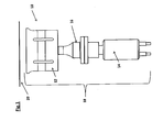
- Fig. 1 shows a schematic representation of an exemplary embodiment of an ultrasound system 10 of a device for sealing, joining, separating, perforating and / or embossing of materials such as in particular plastics, films, nonwovens, fabrics / textiles and / or paper, including the production of packaging suitable is.
- the ultrasound system 10 comprises at least one oscillating structure 18 having a sonotrode 12, a converter 14 and optionally an amplitude transformation piece 16, an ultrasound generator (not shown) exciting the converter 14 and an anvil 20 opposite the sonotrode 12.
- the sonotrode 12 and the anvil 20 may contact each other be moved to and away from each other.
- Fig. 2 shows a schematic perspective view of an exemplary embodiment of a sonotrode support system 22 according to the invention, which may for example be associated with the sonotrode 12 of such an ultrasound system 10, as shown in the Fig. 1 is shown.
- the sonotrode support system 22 comprises at least one generally U-shaped bracket 24, which can be supported on a support (not shown), with a web 26 and two limbs 28 which can each be resiliently tilted about a node 30 provided in the region of the web 26 and between which an ultrasound Sonotrode 12 is clamped, with at clamped sonotrode 12 at least the free ends 28 'of the legs 28 abut against this sonotrode 12 and engage with this and the clip 24 is supported in the web area on the carrier.
- the sonotrode 12 may have a generally cuboidal, elongated shape, and the two legs 28 of a respective bracket 24 may extend at two opposite longitudinal sides 38 of the sonotrode 12 generally perpendicular to the longitudinal axis of the sonotrode between these clamped sonotrode 12.
- the web 26 of the generally U-shaped clamp 24 is arranged on the sonotrode side 42 opposite the contact side 40 of the sonotrode 12 which comes into contact with the materials to be processed. Between this contact side 40 opposite Sonotrodenseite 42 and the web 26 of the bracket 24, a free space 44 is provided.
- Fig. 3 in which the sonotrode support system 22 according to Fig. 2 is shown in a schematic cross-sectional representation, in the present case, the free ends 28 'of the legs 28 of a respective generally U-shaped bracket 24, for example, each provided with a notch 32, engages in the clamped sonotrode 12 provided on the sonotrode 12 lug 34 ,
- the respective cooperating lugs 34 and notches 32 are dimensioned such that the tilting movements of the legs 28 around the node 30 that occur when the sonotrode 12 is clamped in are not hindered.
- a respective generally U-shaped bracket 24 is preferably mounted in the node 30 of the tilting movements or supported on the carrier.
- these recesses 36 may be introduced in particular from opposite sides of the web 26 forth and each extending parallel to the sonotrode longitudinal direction.
- the web 26 of a respective generally U-shaped bracket 24 may be divided into two each one of the two legs 28 associated web portions 26 ', 26 ", which are in particular releasably connectable to form the U-shaped bracket 24 and its web 26. These web sections 26 ', 26 "can be screwed together, for example. As based on the FIGS. 2 and 3 can be seen, in each web portion 26 '26 "each one the tilting movement of the associated leg 28 supporting recess 36 is provided.
- the free ends 28 'of the legs 28 of a respective generally U-shaped bracket 24 preferably engage the vibration node of the longitudinal vibration generated in the sonotrode 12 at the sonotrode 12. In the present case, therefore, the projections 34 and notches 32 in Vibration node of the generated in the sonotrode 12 longitudinal vibration with each other.
- the web portions 26 ', 26 "forming the web 26 of a respective generally U-shaped bracket 24 can each be designed as a base-like foot adjoining the relevant end of the associated leg 28.
- the node 30 of the tilting movements is preferably located on the from the legs 28 side facing away from the web 26 and the web portions 26 ', 26 ". With this web surface facing away from the legs 28, a respective generally U-shaped bracket 24 can then be supported, for example, on a carrier, for example carrier plate.
- the holder engages in the vibration node of the longitudinal vibration generated in the sonotrode at the sonotrode and is braced there.
- the there, i. Occurring in the region of the free leg ends transverse expansion movement of the sonotrode causes a Mitbe admire the respective generally U-shaped bracket in the form of a transverse vibration.
- the respective generally U-shaped bracket may be located at the junction of this tilting movement, which may in particular be on the leg's opposite end surface, for example on a support, e.g. a support plate to be fixed.
- the parts carrying the oscillatory structure can be made more solid, which makes the mounting more robust.
- a respective generally U-shaped bracket is mounted in the node of the tilting vibration.
Landscapes
- Engineering & Computer Science (AREA)
- Mechanical Engineering (AREA)
- Life Sciences & Earth Sciences (AREA)
- Forests & Forestry (AREA)
- Lining Or Joining Of Plastics Or The Like (AREA)
- Treatment Of Fiber Materials (AREA)
- Percussion Or Vibration Massage (AREA)
- Apparatuses For Generation Of Mechanical Vibrations (AREA)
- Pressure Welding/Diffusion-Bonding (AREA)
Applications Claiming Priority (1)
| Application Number | Priority Date | Filing Date | Title |
|---|---|---|---|
| DE102010018444A DE102010018444A1 (de) | 2010-04-27 | 2010-04-27 | Sonotrodenhalterungssystem |
Publications (2)
| Publication Number | Publication Date |
|---|---|
| EP2383066A2 true EP2383066A2 (fr) | 2011-11-02 |
| EP2383066A3 EP2383066A3 (fr) | 2014-08-13 |
Family
ID=44343771
Family Applications (1)
| Application Number | Title | Priority Date | Filing Date |
|---|---|---|---|
| EP11003460.0A Withdrawn EP2383066A3 (fr) | 2010-04-27 | 2011-04-27 | Système de fixation de sonotrodes |
Country Status (3)
| Country | Link |
|---|---|
| US (1) | US20110259526A1 (fr) |
| EP (1) | EP2383066A3 (fr) |
| DE (1) | DE102010018444A1 (fr) |
Cited By (1)
| Publication number | Priority date | Publication date | Assignee | Title |
|---|---|---|---|---|
| DE102021124104A1 (de) | 2021-09-17 | 2023-03-23 | Telsonic Holding Ag | Ultraschallsonotrode und Ultraschallschwingvorrichtung |
Families Citing this family (2)
| Publication number | Priority date | Publication date | Assignee | Title |
|---|---|---|---|---|
| EP2368694A1 (fr) * | 2010-03-22 | 2011-09-28 | Tetra Laval Holdings & Finance S.A. | Sonotrode |
| DE102017220079A1 (de) * | 2017-11-10 | 2019-05-16 | Schunk Sonosystems Gmbh | Ultraschall-Schweißeinrichtung |
Citations (1)
| Publication number | Priority date | Publication date | Assignee | Title |
|---|---|---|---|---|
| DE202004003917U1 (de) | 2004-03-12 | 2004-05-19 | Sonotronic Nagel Gmbh | Sonotrodenwerkzeug für eine Sonotrode |
Family Cites Families (14)
| Publication number | Priority date | Publication date | Assignee | Title |
|---|---|---|---|---|
| JPH03183527A (ja) * | 1989-12-13 | 1991-08-09 | Hitachi Constr Mach Co Ltd | 超音波接合装置 |
| DE4313875C3 (de) * | 1993-04-28 | 2001-01-18 | Karl Widmann Schweismaschinen | Vorrichtung zum Herstellen von Einsteckhüllen oder Einbanddecken |
| DE29601393U1 (de) * | 1996-01-17 | 1996-04-04 | Dr. Hielscher GmbH, 14532 Stahnsdorf | Ultraschall-Sonotrode mit Flansch |
| JP3215084B2 (ja) * | 1998-04-28 | 2001-10-02 | 株式会社アルテクス | 超音波振動接合用共振器 |
| JP3290632B2 (ja) * | 1999-01-06 | 2002-06-10 | 株式会社アルテクス | 超音波振動接合装置 |
| CA2314733A1 (fr) * | 1999-08-02 | 2001-02-02 | Ultex Corporation | Outil de liaison a vibrations ultrasonores |
| JP4603122B2 (ja) * | 2000-02-23 | 2010-12-22 | 四国化工機株式会社 | 超音波シール装置 |
| EP1719605B1 (fr) * | 2004-02-25 | 2015-07-08 | Zuiko Corporation | Systeme de soudage d'ame |
| US7344620B2 (en) * | 2004-05-10 | 2008-03-18 | Bandelin Electronic Gmbh & Co. Kg | Ultrasonic sonotrode |
| JP2006239749A (ja) * | 2005-03-04 | 2006-09-14 | Toray Eng Co Ltd | 超音波接合方法および超音波接合装置 |
| US7748590B2 (en) * | 2005-05-16 | 2010-07-06 | Ford Global Technologies, Llc | Ultrasonic welding apparatus |
| DE102005038344A1 (de) * | 2005-08-13 | 2007-02-15 | Tetra Laval Holdings & Finance S.A. | Vorrichtung zum Ultraschallbearbeiten von Werkstücken |
| ES2377887T3 (es) * | 2007-04-30 | 2012-04-02 | Stryker Trauma Gmbh | Dispositivo para preparar una cavidad simétrica no rotacional en un hueso |
| JP4564548B2 (ja) * | 2008-04-28 | 2010-10-20 | 株式会社アルテクス | 超音波振動接合用共振器とそれを支持する支持装置 |
-
2010
- 2010-04-27 DE DE102010018444A patent/DE102010018444A1/de not_active Withdrawn
-
2011
- 2011-04-27 EP EP11003460.0A patent/EP2383066A3/fr not_active Withdrawn
- 2011-04-27 US US13/095,079 patent/US20110259526A1/en not_active Abandoned
Patent Citations (1)
| Publication number | Priority date | Publication date | Assignee | Title |
|---|---|---|---|---|
| DE202004003917U1 (de) | 2004-03-12 | 2004-05-19 | Sonotronic Nagel Gmbh | Sonotrodenwerkzeug für eine Sonotrode |
Cited By (1)
| Publication number | Priority date | Publication date | Assignee | Title |
|---|---|---|---|---|
| DE102021124104A1 (de) | 2021-09-17 | 2023-03-23 | Telsonic Holding Ag | Ultraschallsonotrode und Ultraschallschwingvorrichtung |
Also Published As
| Publication number | Publication date |
|---|---|
| EP2383066A3 (fr) | 2014-08-13 |
| US20110259526A1 (en) | 2011-10-27 |
| DE102010018444A1 (de) | 2011-10-27 |
Similar Documents
| Publication | Publication Date | Title |
|---|---|---|
| DE102009027021B3 (de) | Ultraschall-Schweißvorrichtung und Verfahren zum Verschweißen zweier Bauteile | |
| DE4448017B4 (de) | Vorrichtung und Verfahren zum Sieben,Klassieren, Sichten, Filtern oder Sortieren von Stoffen | |
| EP2288450B1 (fr) | Sonotrode pour une unité émettrice d'ultrasons | |
| DE102010029395A1 (de) | Torsionssonotrode, Ultraschall-Schweißvorrichtung und Verfahren zur Herstellung einer Schweißverbindung mittels Ultraschall | |
| DE4439470C1 (de) | Vorrichtung zum Ultraschallbearbeiten eines Werkstücks | |
| EP3096935B1 (fr) | Procédé d'assemblage de matière plastique renforcée par des fibres | |
| EP2065146A1 (fr) | Dispositif de coupe à vibrations et procédé destiné à la coupe à vibrations | |
| EP3645204A1 (fr) | Procédé et ensemble servant à raccorder de manière électroconductrice des conducteurs à un dispositif de maintien | |
| DE102016208650A1 (de) | Verfahren zur Herstellung eines schienenförmigen Hybridbauteils sowie ein derartiges Hybridbauteil | |
| DE102010005230A1 (de) | Vorrichtung und Verfahren zur Ultraschall-Materialbearbeitung | |
| DE102013107154B4 (de) | Antriebsvorrichtung | |
| DE102011118208A1 (de) | Ultraschall-Schneidevorrichtung | |
| EP2383066A2 (fr) | Système de fixation de sonotrodes | |
| DE112010001902T5 (de) | Ergonomisches Horn | |
| WO2018041811A1 (fr) | Système générateur d'ultrasons comportant un transformateur d'amplitude raccordé par la surface extérieure | |
| EP2847464B1 (fr) | Dispositif et ensemble pour production d'un courant d'air | |
| EP3592498B1 (fr) | Dispositif de soudage par ultrasons et procédé de soudage par ultrasons | |
| EP3556540A1 (fr) | Dispositif de soudage par vibrations, procédé de raccordement d'au moins deux pièces de construction allongées au moyen d'un soudage par vibrations ainsi que procédé de fabrication du dispositif de soudage par vibrations | |
| EP2331268B1 (fr) | Dispositif pour générer des vibrations à haute fréquence et procédé pour faire fonctionner ce dispositif | |
| WO1999046061A1 (fr) | Procede pour activer une monture de tamis avec des ultrasons | |
| DE102019211778B4 (de) | Übertragerstruktur, Vorrichtung und Verwendung einer Übertragerstruktur oder Vorrichtung | |
| EP1034726A1 (fr) | Procédé d'assemblage d'une pièce d'ancrage en matière plastique à un élément de construction en bois, pièce d'ancrage, élément de construction et sommier à lattes selon ce procédé | |
| EP3600700B1 (fr) | Système d'usinage torsionnel par ultrasons et procédé de réglage d'un oscillateur torsionnel | |
| EP2261008A1 (fr) | Procédé et dispositif de traitement par ultrasons | |
| EP2708291A2 (fr) | Support de sonotrodes |
Legal Events
| Date | Code | Title | Description |
|---|---|---|---|
| AK | Designated contracting states |
Kind code of ref document: A2 Designated state(s): AL AT BE BG CH CY CZ DE DK EE ES FI FR GB GR HR HU IE IS IT LI LT LU LV MC MK MT NL NO PL PT RO RS SE SI SK SM TR |
|
| AX | Request for extension of the european patent |
Extension state: BA ME |
|
| PUAI | Public reference made under article 153(3) epc to a published international application that has entered the european phase |
Free format text: ORIGINAL CODE: 0009012 |
|
| RAP1 | Party data changed (applicant data changed or rights of an application transferred) |
Owner name: MS SPAICHINGEN GMBH |
|
| PUAL | Search report despatched |
Free format text: ORIGINAL CODE: 0009013 |
|
| AK | Designated contracting states |
Kind code of ref document: A3 Designated state(s): AL AT BE BG CH CY CZ DE DK EE ES FI FR GB GR HR HU IE IS IT LI LT LU LV MC MK MT NL NO PL PT RO RS SE SI SK SM TR |
|
| AX | Request for extension of the european patent |
Extension state: BA ME |
|
| RIC1 | Information provided on ipc code assigned before grant |
Ipc: B29C 65/08 20060101ALI20140704BHEP Ipc: B06B 3/00 20060101AFI20140704BHEP Ipc: B23K 20/10 20060101ALI20140704BHEP Ipc: B26D 7/00 20060101ALI20140704BHEP |
|
| STAA | Information on the status of an ep patent application or granted ep patent |
Free format text: STATUS: THE APPLICATION IS DEEMED TO BE WITHDRAWN |
|
| 18D | Application deemed to be withdrawn |
Effective date: 20141101 |