EP2383355B1 - Faisceau pour pompe à jet et son procédé de fabrication - Google Patents
Faisceau pour pompe à jet et son procédé de fabrication Download PDFInfo
- Publication number
- EP2383355B1 EP2383355B1 EP09833321.4A EP09833321A EP2383355B1 EP 2383355 B1 EP2383355 B1 EP 2383355B1 EP 09833321 A EP09833321 A EP 09833321A EP 2383355 B1 EP2383355 B1 EP 2383355B1
- Authority
- EP
- European Patent Office
- Prior art keywords
- jet pump
- pump beam
- less
- nickel base
- alloy
- Prior art date
- Legal status (The legal status is an assumption and is not a legal conclusion. Google has not performed a legal analysis and makes no representation as to the accuracy of the status listed.)
- Active
Links
Images


Classifications
-
- G—PHYSICS
- G21—NUCLEAR PHYSICS; NUCLEAR ENGINEERING
- G21C—NUCLEAR REACTORS
- G21C15/00—Cooling arrangements within the pressure vessel containing the core; Selection of specific coolants
- G21C15/24—Promoting flow of the coolant
- G21C15/243—Promoting flow of the coolant for liquids
- G21C15/25—Promoting flow of the coolant for liquids using jet pumps
-
- C—CHEMISTRY; METALLURGY
- C22—METALLURGY; FERROUS OR NON-FERROUS ALLOYS; TREATMENT OF ALLOYS OR NON-FERROUS METALS
- C22C—ALLOYS
- C22C19/00—Alloys based on nickel or cobalt
- C22C19/03—Alloys based on nickel or cobalt based on nickel
- C22C19/05—Alloys based on nickel or cobalt based on nickel with chromium
- C22C19/051—Alloys based on nickel or cobalt based on nickel with chromium and Mo or W
- C22C19/055—Alloys based on nickel or cobalt based on nickel with chromium and Mo or W with the maximum Cr content being at least 20% but less than 30%
-
- C—CHEMISTRY; METALLURGY
- C22—METALLURGY; FERROUS OR NON-FERROUS ALLOYS; TREATMENT OF ALLOYS OR NON-FERROUS METALS
- C22C—ALLOYS
- C22C19/00—Alloys based on nickel or cobalt
- C22C19/03—Alloys based on nickel or cobalt based on nickel
- C22C19/05—Alloys based on nickel or cobalt based on nickel with chromium
- C22C19/051—Alloys based on nickel or cobalt based on nickel with chromium and Mo or W
- C22C19/056—Alloys based on nickel or cobalt based on nickel with chromium and Mo or W with the maximum Cr content being at least 10% but less than 20%
-
- C—CHEMISTRY; METALLURGY
- C22—METALLURGY; FERROUS OR NON-FERROUS ALLOYS; TREATMENT OF ALLOYS OR NON-FERROUS METALS
- C22F—CHANGING THE PHYSICAL STRUCTURE OF NON-FERROUS METALS AND NON-FERROUS ALLOYS
- C22F1/00—Changing the physical structure of non-ferrous metals or alloys by heat treatment or by hot or cold working
- C22F1/10—Changing the physical structure of non-ferrous metals or alloys by heat treatment or by hot or cold working of nickel or cobalt or alloys based thereon
-
- Y—GENERAL TAGGING OF NEW TECHNOLOGICAL DEVELOPMENTS; GENERAL TAGGING OF CROSS-SECTIONAL TECHNOLOGIES SPANNING OVER SEVERAL SECTIONS OF THE IPC; TECHNICAL SUBJECTS COVERED BY FORMER USPC CROSS-REFERENCE ART COLLECTIONS [XRACs] AND DIGESTS
- Y02—TECHNOLOGIES OR APPLICATIONS FOR MITIGATION OR ADAPTATION AGAINST CLIMATE CHANGE
- Y02E—REDUCTION OF GREENHOUSE GAS [GHG] EMISSIONS, RELATED TO ENERGY GENERATION, TRANSMISSION OR DISTRIBUTION
- Y02E30/00—Energy generation of nuclear origin
- Y02E30/30—Nuclear fission reactors
Definitions
- the present invention relates to a jet pump beam used in a jet pump for forcibly circulating high-temperature and high-pressure water (coolant) in a boiling water reactor (BWR), and a method for producing the jet pump beam. Moreover, the present invention relates to a jet pump beam made of an improved heat-treated precipitation-hardened nickel base alloy excellent in anti-stress corrosion cracking properties and having a high elastic modulus and high-temperature strength produced by said method.
- some boiling water reactors comprise an external recirculation system for forcibly feeding a coolant into a reactor core.
- a jet pump connected to the external recirculation system is provided in a reactor pressure vessel (RPV).
- RSV reactor pressure vessel
- a plurality of sets of jet pumps are provided in an annular downcomer portion between the reactor pressure vessel and a core shroud.
- Each of the jet pumps is provided in the downcomer portion in the reactor pressure vessel, and comprises a riser pipe, a transition piece, an inlet mixer, and a diffuser.
- the transition piece is formed integrally on the riser pipe, to constitute a bifurcated portion on a head portion of the riser pipe.
- the coolant is divided into two streams in the transition piece, and respectively guided to an elbow of the inlet mixer that forms a turn-around flow path.
- the elbow is press-supported by a jet pump beam made of a spring member, and thereby prevented from moving upward.
- inconel X-750 alloy that is precipitation-hardened Ni base alloy having a high elastic modulus and high-temperature strength has been conventionally used for the pump beam of the jet pump as disclosed in Japanese Patent Laid-Open No. 59-85834 (Patent Document 1).
- Patent Document 1 An example in which the inconel X-750 alloy is used for a reactor member is also disclosed in Patent Document 2 (Japanese Patent Laid-Open No. 05-164886 ).
- Patent Documents 3 and 4 It is also disclosed in Japanese Patent Laid-Open Nos. 2004-91816 and 04-297537 (Patent Documents 3 and 4) that inconel 718 alloy that is normal heat-treated precipitation-hardened nickel base alloy is also used for a reactor member as a high-strength material having corrosion resistance and high-temperature resistance.
- the inconel X-750 alloy as the precipitation-hardened nickel base alloy having a high elastic modulus and high-temperature strength is used for the jet pump beam of the jet pump disclosed in Patent Document 1, which is used under a high-temperature and high-pressure water environment in the boiling water reactor.
- the inconel X-750 alloy has a high elastic modulus and high-temperature strength as the material for constituting the jet pump beam
- the inconel X-750 alloy has a problem that stress corrosion cracking (SCC) sensitivity is high under a high-temperature and high-pressure water environment, and stress corrosion cracking occurs under a high-temperature and high-pressure environment during operation of the nuclear reactor.
- SCC stress corrosion cracking
- the inconel 718 alloy disclosed in Patent Document 3 as the nickel base alloy is used for the reactor member in a similar manner to the inconel X-750 alloy. It is disclosed that heat treatment on the inconel 718 alloy is performed by subjecting the material to solution heat treatment at 995°C to 1040°C, keeping the material at 760°C for 5 hours, cooling (furnace cooling) the material from 760°C to 650°C inside a furnace, keeping the material at 650°C for 1 hour, and subjecting the material to age-hardening treatment for cooling.
- ASTM (American Society for Testing and Materials) B637 also describes an example in which normal heat-treated inconel 718 alloy is subjected to solution heat treatment at 924°C to 1010°C, kept at 718°C for 8 hours, cooled inside a furnace, further kept at 620°C for 8 hours, and then subjected to age-hardening treatment for air-cooling.
- the normal heat-treated inconel 718 alloy subjected to the normal heat treatment is a material excellent in high-temperature strength as disclosed in ASTM or the like, the normal heat-treated inconel 718 alloy also has a problem that ductility is poor.
- JP 61-079743 A discloses a nickel-based alloy as a spring material for jet pumps in boiling water-type nuclear reactors, wherein the alloy comprises (wt.%) 50-55 Ni, 17-21 Cr, 4-6 (Nb + Ta), 2-4 Mo, 0.1-1.5 Al, 0.1-2 Ti and balance Fe, wherein the alloy is solution heat treated at 920 to 1200 °C, primarily aged at 698 to 738 °C for about 5 to 10 hr, then furnace cooled, and finally further secondarily aged at 601 to 640 °C for about 5 to 10 hr.
- JP 63-096214 A relates to the production of a high-strength high-toughness spring material having excellent SCC resistance, wherein the alloy contains, by weight, ⁇ 0.08 % C, ⁇ 0.35 % Si, ⁇ 0.35 % Mn, ⁇ 0.015 % S, 17.0 to 21.0 % Cr, ⁇ 0.015 % P, 0.20 to 0.80 % Al, 0.65 to 1.15 % Ti, ⁇ 0.006 % B, 4.75 to 5.50 % Nb + Ta, ⁇ 0.30 % Cu, ⁇ 1.0 % Co (where 50.0 to 55.0 % Ni + Co), 2.80 to 3.30 % Mo and the balance Fe and incidental impurities, wherein the alloy is subjected to a solution heat treatment by heating for 15 min or more at 950 to 1150 °C, to cold spring working to the desired shape, and finally to an aging heat treatment involving holding for 4 to 10 hr at 690 to 710 °C.
- the present invention provides a method according to claim 1 and a jet pump beam according to claim 4.
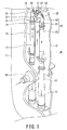
- Fig. 1 is a perspective view illustrating an installation example of a jet pump comprising a jet pump beam.
- a jet pump 10 is mounted in an annular downcomer portion 13 between a reactor pressure vessel (RPV) 11 and a core shroud 12 of a boiling water reactor (BWR).
- the core shroud 12 is formed in a cylindrical shape so as to surround a reactor core 14.
- a plurality of unillustrated fuel assemblies are loaded in the reactor core 14.
- a plurality of sets of jet pumps 10, e.g., 10 sets of jet pumps 10 (20 jet pumps) are provided in the downcomer portion 13 in the reactor pressure vessel 11 at predetermined intervals in a circumferential direction.
- Each of the jet pumps 10 is connected to an external reactor recirculation system (not shown) inside the reactor pressure vessel 11.
- the jet pump 10 forcibly feeds a coolant into the reactor core 14 so as to reduce a coolant flow rate to be drawn into the external reactor recirculation system.
- the jet pump 10 mainly comprises a riser pipe 17 as a coolant supply pipe extending from a recirculation inlet nozzle 16, a transition piece 18, inlet mixers 20 having paired elbows 19, and diffusers 21.
- the transition piece 18 is provided integrally on a top portion of the riser pipe 17, to divide a coolant flow rising through the riser pipe 17 into two streams and guide the streams to the elbows 19 of the inlet mixers 20.
- each of the pair of elbows 19 and 19, a jet pump nozzle 22, and an inlet throat 23 are integrally provided.
- the elbow 19 turns around the coolant from the riser pipe 17.
- the jet pump nozzle 22 is a mixing nozzle for ejecting the coolant turned around in the elbow 19.
- the inlet throat 23 captures and mixes surrounding reactor water with the coolant ejected from the jet pump nozzle 22 on an inlet side of the downcomer portion 13.
- the coolant guided into the inlet throat 23 is mixed with the reactor water inflowing from a peripheral area and guided into the diffuser 21.
- the mixed water falls through the diffuser 21 to be guided into a core lower plenum in the reactor pressure vessel 11.
- the mixed water guided to the core lower plenum is turned around therein to be guided into the reactor core 14.
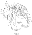
- a pair of gate-type support posts 25 and 25 are vertically arranged facing each other on both sides of a bifurcated portion of the transition piece 18.
- Horizontally-long groove portions (notches) 26 and 26 are respectively provided in a substantially horizontal direction at positions facing each other in upper end portions of the support posts 25 and 25.
- the groove portions 26 and 26 constitute pockets.
- Both ends of a jet pump beam 27 are engaged with the groove portions 26 and 26 so as to press-support each of the elbows 19 of the inlet mixers 20 from above.
- the both end portions of the jet pump beam 27 have a rectangular shape in cross section, and are engaged to support the elbow 19 in surface contact with upper end surfaces of the groove portions 26 and 26 of the support posts 25.
- the jet pump beam 27 is made of a high elastic material having a high elastic modulus as a spring member (an elastic body).
- the jet pump beam 27 has a sectional area increasing toward a center portion of a beam longitudinal direction.
- reference numeral 28 denotes a hanging bolt of the inlet mixer 20.
- a head bolt 30 as a pressing constituent member for pressing the elbow 19 down from above is provided in the center portion of the jet pump beam 27.
- a vertical threaded hole 31 is vertically formed through the center portion of the jet pump beam 27 perpendicular to the beam longitudinal direction as shown in Fig. 3 .
- the head bolt 30 is screwed into the vertical threaded hole 31 so as to penetrate through the vertical threaded hole 31.
- the head bolt 30 is a polygonal bolt such as a hexagon bolt.
- a male thread 32 of the head bolt 30 is screwed into the vertical threaded hole 31 of the jet pump beam 27.
- a distal end thereof (a lower end) is in press-contact with a top portion of the elbow 19 of the inlet mixer 20.
- a seat portion is provided on the tope portion of the elbow of the inlet mixer 20.
- An arc or semi-round-headed boss portion 33 formed at the lower end of the head bolt 30 is in press-contact with a spherical seat (not shown) provided in the seat portion.
- the elbow 19 of the inlet mixer 20 is detachably installed on the transition piece 18 by a bolt fixing device 35 of the jet pump beam 27.
- the bolt fixing device 35 of the jet pump beam 27 has a configuration as shown in Figs. 3 and 4 .
- the bolt fixing device 35 comprises the head bolt 30 screwed into the vertical threaded hole 31 of the jet pump beam 27, a lock cap 37, a body housing 38, a base plate 39, and a spring member 40 as shown in Fig. 3 .
- the lock cap 37 is fitted to a polygonal head portion 36 of the head bolt 30 in an integrally-rotatable and axially-slidable manner.
- the body housing 38 can accommodate the lock cap 37 selectively at a fixed position and a freely-rotatable position.
- the base plate 39 installs the body housing 38 by fixing the body housing 38 to a top portion base surface 27a of the jet pump beam 27 via a washer or the like.
- the spring member 40 is accommodated in the body housing 38 so as to urge the lock cap 37 upward with a spring urging force.
- the base plate 39 is fixed to the top portion base surface 27a of the jet pump beam 27 with positioning pins 41 and small screws 42 (see Fig. 4 ).
- An inner peripheral flange 39a of the base plate 39 is provided so as to cover an outer peripheral flange 38a in a lower portion of the body housing 38 while pressing the outer peripheral flange 38a from above.
- reference numeral 45 denotes a trunnion formed integrally with the jet pump beam 27.
- the base plate 39 comprises a rotation restraint mechanism 44 for restraining rotation of the body housing 38 around an axis.
- the rotation restraint mechanism 44 detachably engages the body housing 38 with the base plate 39 to thereby restrain the rotation of the body housing 38.
- Tapered external teeth 48 are circumferentially formed on an outer peripheral portion of the lock cap 37 of the bolt fixing device 35 so as to expand downward.
- An internal tooth-shaped groove 49 of the body housing 38 selectively meshes with the external teeth 48.
- the external teeth 48 of the lock cap 37 mesh with (splined to) the internal tooth-shaped groove 49 of the body housing 38 to be fixed thereto in an integrally-rotatable manner when the lock cap 37 moves upward to assume a left-side position in Fig. 3 .
- the external teeth 38 are freely rotatable.
- a lower portion of an inner peripheral wall of the freely-rotatable body housing 38 is formed flush with a bottom portion of the internal tooth-shaped groove 49 on the same inner peripheral surface.
- the lock cap 37 and the body housing 38 are made of a hard material such as nickel base alloy. At least the external teeth 48 of the lock cap 37 and the internal tooth-shaped groove 49 of the body housing 38 are made of a hard material. A hard weld overlay material or a weld overlay material containing cobalt is used.
- the lock cap 37 is compressed against a spring urging force of the spring member (the elastic body) 40, so that the external teeth 48 of the lock cap 37 and the internal tooth-shaped groove 49 of the body housing 38 are disengaged from each other, and the lock cap 37 assumes a freely-rotatable position as shown on the right half side of Fig. 3 . Accordingly, the head bolt 30 can be freely rotated, and the head bolt 30 becomes freely rotatable with respect to the jet pump beam 27. The head bolt 30 can be thereby rotated to move up and down.
- the inlet mixer 20 is installed on a seat surface of the transition piece 18 on the riser pipe 17 of the jet pump by being press-supported by the bolt fixing device 35 by use of the jet pump beam 27.
- the jet pump 10 divides the cooling water rising through the riser pipe 17 into two streams in the transition piece 18 and guides the streams to the pair of elbows 19.
- the cooling water is turned around in the elbows 19 of the inlet mixers 20, and ejected downward toward suction ports of the inlet throats 23 from the jet pump nozzles 22 on the both outer sides as shown in Fig. 1 .
- the cooling water captures, in the downcomer portion 13, saturated water (coolant) separated through a steam-water separator and a steam dryer (both are not shown) in a reactor core upper portion, and is sucked from a low-pressure area generated at outlets of the jet pump nozzles 22 into the inlet throats 23.
- the mixed fluid restores its pressure in the diffusers 21 and is then sent to the reactor core lower plenum.
- the coolant ejected from the jet pump 10 is turned around in the core lower plenum and guided to the reactor core 14.
- the coolant is heated while passing through the core 14 to result in an air-water mixed two-phase flow, which rises upward, is sent to the unillustrated steam-water separator to be separated, sent to the steam dryer (not shown) to be dried, and sent to a steam turbine from a main steam outlet.
- the saturated water guided to the downcomer portion 13 partly moves downward through the downcomer portion 13 and is drawn from an outlet nozzle into two series of recirculation loops.
- a pressure thereof is increased by a recirculation pump (not shown).
- the saturated water is sent to the riser pipe 17 from the recirculation inlet nozzle 16 of the jet pump 10, rises through the riser pipe 17, is turned around in the elbows 19 of the inlet mixers 20, and ejected again from the jet pump nozzles 22.
- a reactor member that is a spring member made of an improved heat-treated precipitation-hardened nickel base alloy (improved heat-treated inconel 718 alloy) material shown in Fig. 5 is used as the jet pump beam 27 of the jet pump 10.
- the jet pump beam 27 is made of the improved heat-treated precipitation-hardened nickel base alloy (improved heat-treated inconel 718 alloy) material obtained by improving heat treatment such as solution heat treatment and age-hardening heat treatment on conventional normal heat-treated precipitation-hardened inconel 718 alloy.
- the jet pump beam 27 is made of the improved heat-treated precipitation-hardened nickel base alloy (improved heat-treated inconel 718 alloy) material.
- a material used for the improved heat-treated precipitation-hardened nickel base alloy is similar to a material defined and prescribed in JIS G4901, AMS 5662, and ASTM B670.
- the improved heat-treated nickel base alloy used for the jet pump beam 27 is equivalent to inconel 718 alloy, and its chemical component elements are represented by mass% as follows.
- the jet pump beam 27 is produced from the improved heat-treated precipitation-hardened nickel base alloy obtained by subjecting to improved solution heat treatment and age-hardening heat treatment, a precipitation-hardened nickel base alloy (inconel 718 alloy) material having a component composition containing by mass%, Ni: 50.0% to 55.0%, Cr: 17.0% to 21.0%, Nb+Ta: 4.75% to 5.50%, Mo: 2.8% to 3.3%, Ti: 0.65% to 1.15%, Al: 0.2% to 0.8%, C: 0.08% or less, Si: 0.35% or less, Mn: 0.35% or less, S: 0.015% or less, P: 0.03% or less, Cu: 0.30% or less, B: 0.006% or less, and Co: 1.0% or less, and Fe and inevitable impurities constituting a remaining part (balance).
- the jet pump beam 27 produced as described above is used in the jet pump 10 as the reactor member.
- the precipitation-hardened nickel base alloy is subjected to heat treatment such as the improved solution heat treatment and age-hardening heat treatment.
- the heat treatment is performed by melting the precipitation-hardened nickel base alloy material, die forging the material, subjecting the die forged material to solution heat treatment at 1010°C to 1090°C, finishing the material by machining or cold working, and subjecting the finished material to age-hardening heat treatment at 694°C to 714°C for 5 to 7 hours, to thereby obtain the improved heat-treated precipitation-hardened nickel base alloy (improved heat-treated inconel 718 alloy).
- composition elements of the improved heat-treated precipitation-hardened nickel base alloy are equivalent to those of normal heat-treated (ASTM B637) inconel 718 alloy.
- the heat treatment in which the solution heat treatment and the age-hardening heat treatment are improved is applied thereto, to thereby produce the improved heat-treated precipitation-hardened nickel base alloy.
- the improved heat-treated inconel 718 alloy has an excellently smaller stress corrosion cracking sensitivity under a high-temperature water environment than that of the normal heat-treated inconel 718 alloy or inconel X-750 alloy. It has been found as technical findings that since the stress corrosion cracking sensitivity is small, anti-stress corrosion cracking properties can be improved.
- the stress corrosion cracking is known to occur when three elements of existence of a tensile stress, usage environment conditions, and characteristics of a material itself are satisfied. In order to prevent the stress corrosion cracking, the anti-stress corrosion cracking properties are improved by improving the characteristics of the material itself and reducing the stress corrosion cracking sensitivity.
- the jet pump beam 27 is used under a high-temperature and high-pressure radiation environment in a light water reactor, an upper limit is set for the composition elements Co and B of the jet pump beam 27 from the viewpoint of radiation. Practically, it is preferable that C content is set to 0,05% or less, and B content is set to 0.001% or less.
- the material used for the jet pump beam 27 has a component composition similar to that defined in JIS G4901, AMS 5661 and ASTM B670 or the like.
- the strength of the material can be further improved by precipitating ⁇ "-phase Ni 3 Nb as a precipitate by the heat treatment.
- Ni is a main element of the improved heat-treated nickel base alloy, and is a constituent element of ⁇ "-phase and ⁇ '-phase precipitates.
- a content rate of Fe is relatively increased, and parent phase stability is reduced. Therefore, a content rate of Ni is set to a range of 50% to 55%.
- Cr is an element necessary for ensuring corrosion resistance against high-temperature and high-pressure water.
- a content rate of Cr is less than 17%, sufficient corrosion resistance cannot be provided.
- the content rate of Cr exceeds 21%, a precipitation amount of Cr carbide into grain boundary increases in use at high temperature. Therefore, the content rate of Cr is set to 17% to 21%.
- Nb is an element necessary for improving high-temperature strength by precipitation hardening, and is a constituent element of ⁇ " phase (Ni 3 Nb) that is a main precipitate of the improved heat-treated nickel base alloy.
- a chemical composition rate of Nb is preferably set to 4.75% to 5.5%.
- Nb content is less than 4.75%, it is difficult to ensure a necessary amount of ⁇ "-phase (Ni 3 Nb) precipitate for stable strength, so that the material is insufficiently precipitation-hardened.
- Nb content exceeds 5.5%, a formation amount of non-solid NbC increases, which is not preferable.
- a total rate of Nb+Ta may be 4.75% to 5.5%.
- Mo is an element which affects solid solution strengthening of the improved heat-treated nickel base alloy.
- Mo content is less than 2.8%, a solid solution strengthening effect is small.
- Mo content exceeds 3.3%, a precipitation amount of M6C carbide is increased in use at high temperature, which is not preferable. Therefore, a composition rate of Mo is preferably 2.8% to 3.3%.
- Ti is an element preferably improving high-temperature strength by forming an intermetallic compound with fine Ni, and affects precipitation strength by forming ⁇ ' phase (Ni 3 (Al, Ti)) that improves the precipitation strength of the material.
- ⁇ ' phase Ni 3 (Al, Ti)
- Ti content is less than 0.65%
- a precipitation amount of ⁇ ' phase is small.
- Ti content exceeds 1.15%
- a formation amount of non-solid TiC is increased.
- composition rate of Ti is set to 0.65% to 1.15%.
- Al affects precipitation strength by forming ⁇ ' phase (Ni 3 (Al, Ti)) that improves the precipitation strength of the material in a similar manner to Ti.
- ⁇ ' phase Ni 3 (Al, Ti)
- a precipitation amount is small.
- the composition rate of Al exceeds 0.8%, stable precipitation cannot be expected from the relationship between Ti concentration and Nb concentration.
- Al content is set to a range of 0.2% to 0.8%.
- Other elements include Fe and elements inflowing when Fe is added. It is preferable to reduce the other elements as much as possible.
- the improved heat-treated nickel base alloy may also has the minor component composition containing C: 0.08% or less, Mn: 0.35% or less, Si: 0.35% or less, S: 0.15% or less, P: 0.03% or less, preferably 0.015% or less, Cu: 0.30% or less, B: 0.006% or less, and Co: 1.0% or less as defined in JIS G4901, AMS 5662 and ASTM B670.
- C is an element necessary for improving the material strength. When an excessively large amount of C is contained, however, corrosion resistance is deteriorated, and toughness is also reduced. Thus, C content is set to 0.08% or less.
- the mechanical characteristics of the jet pump beam 27 produced from the improved heat-treated nickel base alloy are substantially the same as those of the inconel X-750 alloy used for a conventional jet pump beam.
- the jet pump beam 27 is produced from the improved heat-treated nickel base alloy (improved heat-treated precipitation-hardened inconel 718 alloy) material.
- the jet pump beam 27 is used under a high-temperature and high-pressure environment. Therefore, in order to reduce the stress corrosion cracking sensitivity and ensure easiness of plastic deformation of a metallic material or ductility that represents a state in which the material is easily plastic-deformed at the time of production of the improved heat-treated nickel base alloy, the improved heat-treated precipitation-hardened nickel base alloy is used to produce the jet pump beam 27.
- a solution heat treatment temperature range of the improved heat-treated nickel base alloy is 1010°C to 1090°C.
- the heat treatment is performed at less than 1010°C, a more amount of ⁇ -phase intermetallic compound or the like is precipitated into crystal grain boundary of nickel base alloy, and the ductility cannot be improved.
- the heat treatment is performed at more than 1090°C, crystal grain is coarsened, and the material strength is reduced, so that the target mechanical characteristics may not be obtained.
- a heat treatment temperature range of 1010°C to 1090°C is preferable as the solution heat treatment temperature.
- the age-hardening heat treatment is preferably performed at temperatures close to 704°C as a condition to satisfy the mechanical characteristics of the inconel X-750 alloy at normal temperature.
- a temperature range of 694°C to 714°C is appropriately employed in the age-hardening heat treatment as a temperature range of plus/minus 10°C from 704°C, and as heat treatment on a real structure of the jet pump beam 27, an age-hardening heat treatment time range of 5 to 7 hours that is a range of plus/minus 1 hour from 6 hours as a preferable time length is appropriate as the age-hardening heat treatment time.
- test materials having different component compositions as shown in Examples 1 to 4 were prepared to evaluate the stress corrosion cracking sensitivity of the improved heat-treated inconel 718 alloy.
- the chemical composition of the test material is represented by mass%
- test materials of Examples 1 to 4 shown in Fig. 6 were produced from 4 types of improved heat-treated inconel 718 alloys.
- Precipitation-hardened nickel base alloy inconel 718 alloy
- test pieces having different component compositions were collected from each of the four types of improved heat-treated inconel 718 alloys.
- An evaluation test of stress corrosion cracking sensitivity in water having a high temperature corresponding to a temperature within a reactor pressure vessel was performed on the four types of test pieces. The evaluation test was performed by using a CBB (Creviced Bend Beam) test apparatus 50, for example.
- Figs. 7A and 7B show a structure of the CBB test apparatus 50 for evaluating the stress corrosion cracking sensitivity of a test piece 51.
- the CBB test apparatus 50 clamps and holds the test piece 51 between a pair of test jigs 52a and 52b each having a test surface with a curvature radius of 100R, and tightens the test piece 51 by using bolts 54 and 54.
- the test piece 51 has a rectangular-plate shape having a size of 10mm ⁇ 50mm ⁇ 2mmt, for example.
- graphite wool 55 and spacers 56 are interposed between the test piece 51 and the pair of test jigs 52a and 52b to ensure a gap therebetween.
- a CBB test on the test piece 51 was performed by immersing the test piece 51 in high-temperature and high-pressure pure water having, for example, a temperature of 288°C and a pressure of 7.8 MPa for 500 hours by using an autoclave, dividing the test piece 51 into halves, and examining a maximum crack depth in a halved section.
- the CBB test was repetitively performed on the plurality of, e.g., the five test pieces 51 of each of the four types of improved heat-treated inconel 718 alloy.
- Fig. 8 shows the number of cracks and the maximum crack depth after the CBB test on the test pieces 51 made of the improved heat-treated precipitation-hardened nickel base alloy (improved heat-treated inconel 718 alloy) materials in Examples 1 to 4.
- improved heat-treated inconel 718 alloy no stress corrosion cracking occurred in all the four types of test pieces 51 in Examples 1 to 4. It was thereby confirmed that the stress corrosion cracking sensitivity of the test piece was very small, and excellent anti-stress corrosion cracking properties were obtained.
- An embodiment of the jet pump beam according to the present invention relates to a technique for producing the reactor member made of the improved heat-treated precipitation-hardened nickel base alloy (the improved heat-treated inconel 718 alloy) shown in Fig. 6 , particularly, relates to a technique for producing the jet pump beam 27 shown in Fig. 5 .
- the jet pump beam 27 is produced by melting the precipitation-hardened nickel base alloy (inconel 718 alloy) material having the chemical composition shown in Fig. 6 , subjecting the material to the solution heat treatment within the solution heat treatment temperature range described in the above example forming the material into a product shape of the jet pump beam 27 by machining or cold working after the solution heat treatment, and then performing the predetermined age-hardening heat treatment thereon.
- the inconel 718 alloy is subjected to the solution heat treatment within the temperature range of 1010°C to 1090°C.
- the inconel 718 alloy is subjected to the machining such as hot forging or cold forging, or to the cold working in which a metallic material is subjected to plastic working at a recrystallization temperature or less, and thereby formed into the product shape of the jet pump beam.
- the inconel 718 alloy After being formed into the predetermined product shape, the inconel 718 alloy is subjected to the age-hardening heat treatment at 694 to 714°C for 5 to 7 hours, to thereby produce the jet pump beam.
- the age-hardening heat treatment is performed for a predetermined length of time, ⁇ " phase (Ni 3 Nb) is precipitated in the inconel 718 alloy by the precipitation hardening heat treatment, so that the improved heat-treated inconel 718 alloy is obtained as a high-strength material.
- the high-strength material has poor workability.
- the material is formed into the predetermined product shape by the machining or cold working after the solution heat treatment where the material is easily formed into the product shape.
- the precipitation hardening heat treatment is performed to improve the material strength. Accordingly, the reactor member for the jet pump beam 27 as shown in Fig. 5 is produced.
- the improved heat-treated precipitation-hardened nickel base alloy material was prepared by improving the heat treatment on the precipitation-hardened nickel base alloy (in a material-molten state) having the component composition shown in Fig. 6 , and the jet pump beam 27 was experimentally produced by using this improved heat-treated nickel base alloy.
- die forging was performed after melting the precipitation-hardened nickel base alloy (inconel 718 alloy) material, to roughly form the jet pump beam.
- the inconel 718 alloy was subjected to the solution heat treatment within the predetermined temperature range, and finished by the machining or cold working.
- the age-hardening heat treatment was subsequently performed to produce the improved heat-treated inconel 718 alloy.
- the jet pump beam 27 made of the improved heat-treated inconel 718 alloy was thereby produced as shown in Fig. 5 .
- the jet pump beam 27 is produced as shown in Fig. 5 as the spring member used in an actual boiling water reactor. Even when used under a high-temperature and high-pressure environment, the jet pump beam 27 has excellent anti-stress corrosion cracking properties with small stress corrosion cracking sensitivity, and has a high elastic modulus, high-temperature strength, and excellent ductility.
Landscapes
- Chemical & Material Sciences (AREA)
- Engineering & Computer Science (AREA)
- Mechanical Engineering (AREA)
- Materials Engineering (AREA)
- Physics & Mathematics (AREA)
- Metallurgy (AREA)
- Organic Chemistry (AREA)
- General Engineering & Computer Science (AREA)
- High Energy & Nuclear Physics (AREA)
- Thermal Sciences (AREA)
- Plasma & Fusion (AREA)
- Crystallography & Structural Chemistry (AREA)
- Jet Pumps And Other Pumps (AREA)
- Heat Treatment Of Articles (AREA)
Claims (5)
- Procédé de production d'une poutre pour pompe à jet (27) constitué d'un alliage à base de nickel traité à chaud amélioré, comprenant les étapes suivantes :préparer un matériau d'alliage à base de nickel renforcé par précipitation présentant une composition de composants constituée de, en % en masse, 50,0 % à 55,0 % de Ni, 17,0 % à 21,0 % de Cr, 4,75 % à 5,50 % de Nb+Ta, 2,8 % à 3,3 % de Mo, 0,65 % à 1,15 % de Ti, 0,2 % à 0,8 % d'Al, le reste étant du Fe et des impuretés inévitables, contenant optionnellement en outre 0,08 % ou moins de C, 0,35 % ou moins de Mn, 0,35 % ou moins de Si, 0,015 % ou moins de S, 0,03 % ou moins de P, 0,30 % ou moins de Cu, 0,006 % ou moins de B et 1,0 % ou moins de Co ;former grossièrement le matériau d'alliage à base de nickel à la forme de produit par forgeage en matrice après la fusion du matériau d'alliage à base de nickel ;soumettre le matériau d'alliage à base de nickel formé grossièrement au traitement thermique en solution à une température de 1010°C à 1090°C ;finir le matériau d'alliage à base de nickel par l'usinage ou le travail à froid ; etsoumettre le matériau d'alliage à base de nickel fini au traitement thermique de durcissement par vieillissement à une température de 694° à 714°C pendant 5 à 7 heures.
- Procédé de production d'une poutre pour pompe à jet (27) selon la revendication 1, dans lequel la teneur en B est de 0,001 % ou moins et la teneur en Co est de 0,05 % ou moins en % en masse.
- Procédé de production d'une poutre pour pompe à jet (27) selon la revendication 1 ou 2, dans lequel le traitement de durcissement par vieillissement est exécuté à 704°C et à des températures proches de celle-ci pendant presque 6 heures.
- Poutre pour pompe à jet (27) produite par le procédé selon l'une quelconque des revendications 1 à 3.
- Poutre pour pompe à jet (27) selon la revendication 4, comprenant :un corps constitué d'un matériau élastique ;un trou fileté vertical (31) prévu dans une partie centrale du corps, dans lequel un boulon à tête (30) doit être vissé ; etune surface de support de partie supérieure de corps pour supporter un dispositif de fixation de boulon à tête (35).
Applications Claiming Priority (2)
| Application Number | Priority Date | Filing Date | Title |
|---|---|---|---|
| JP2008318820A JP2010138476A (ja) | 2008-12-15 | 2008-12-15 | ジェットポンプビームおよびその製造方法 |
| PCT/JP2009/070147 WO2010071017A1 (fr) | 2008-12-15 | 2009-12-01 | Faisceau pour pompe à jet et son procédé de fabrication |
Publications (3)
| Publication Number | Publication Date |
|---|---|
| EP2383355A1 EP2383355A1 (fr) | 2011-11-02 |
| EP2383355A4 EP2383355A4 (fr) | 2013-05-15 |
| EP2383355B1 true EP2383355B1 (fr) | 2016-05-25 |
Family
ID=42268690
Family Applications (1)
| Application Number | Title | Priority Date | Filing Date |
|---|---|---|---|
| EP09833321.4A Active EP2383355B1 (fr) | 2008-12-15 | 2009-12-01 | Faisceau pour pompe à jet et son procédé de fabrication |
Country Status (5)
| Country | Link |
|---|---|
| US (1) | US8879683B2 (fr) |
| EP (1) | EP2383355B1 (fr) |
| JP (1) | JP2010138476A (fr) |
| ES (1) | ES2578631T3 (fr) |
| WO (1) | WO2010071017A1 (fr) |
Cited By (1)
| Publication number | Priority date | Publication date | Assignee | Title |
|---|---|---|---|---|
| EP2838355B1 (fr) | 2012-04-20 | 2019-05-08 | Lely Patent N.V. | Dispositif pour saisir de la nourriture |
Families Citing this family (10)
| Publication number | Priority date | Publication date | Assignee | Title |
|---|---|---|---|---|
| JP2012026783A (ja) * | 2010-07-21 | 2012-02-09 | Ihi Corp | Cbb試験治具 |
| US8731127B2 (en) * | 2010-08-04 | 2014-05-20 | Ge-Hitachi Nuclear Energy Americas, Llc | Method and apparatus for a BWR inlet mixer clamp assembly |
| US8731134B2 (en) * | 2010-08-06 | 2014-05-20 | Ge-Hitachi Nuclear Energy Americas Llc | Method and apparatus for a BWR jet pump inlet mixer support |
| CN102181752A (zh) * | 2011-04-21 | 2011-09-14 | 江苏新华合金电器有限公司 | 核电站蒸汽发生器用手孔封盖弹簧材料及其制备方法 |
| JP5755562B2 (ja) * | 2011-12-22 | 2015-07-29 | 株式会社東芝 | ジェットポンプ及びジェットポンプビームのボルト固定装置 |
| US20150107072A1 (en) * | 2013-10-22 | 2015-04-23 | Kazim Ozbaysal | Fatigue resistant turbine through bolt |
| CN104233003B (zh) * | 2014-08-26 | 2017-03-01 | 盐城市鑫洋电热材料有限公司 | 一种高锰镍铬电阻电热合金及其制备方法 |
| CN104762532B (zh) * | 2015-05-03 | 2016-06-29 | 银川博聚工业产品设计有限公司 | 一种耐酸碱化工泵 |
| CN105714166B (zh) * | 2015-05-03 | 2017-08-25 | 江苏明江阀业有限公司 | 一种耐酸碱化工泵 |
| JP6842316B2 (ja) * | 2017-02-17 | 2021-03-17 | 日本製鋼所M&E株式会社 | Ni基合金、ガスタービン材およびクリープ特性に優れたNi基合金の製造方法 |
Family Cites Families (13)
| Publication number | Priority date | Publication date | Assignee | Title |
|---|---|---|---|---|
| JPS57123948A (en) * | 1980-12-24 | 1982-08-02 | Hitachi Ltd | Austenite alloy with stress corrosion cracking resistance |
| JPS5985834A (ja) * | 1982-11-08 | 1984-05-17 | Toshiba Corp | ジエツトポンプビ−ム |
| JPS6179743A (ja) | 1984-09-28 | 1986-04-23 | Toshiba Corp | ニツケル基合金及びその熱処理方法 |
| JPS6277448A (ja) * | 1985-09-30 | 1987-04-09 | Toshiba Corp | 耐SCC性に優れた高強度Ni基合金部材の製造方法 |
| JPS6396214A (ja) * | 1986-10-09 | 1988-04-27 | Toshiba Corp | 耐sccに優れた高強度、高靭性ばね材の製造方法 |
| JPH04297537A (ja) | 1991-03-27 | 1992-10-21 | Nuclear Fuel Ind Ltd | 高温水用Ni基合金 |
| JP2535114B2 (ja) | 1991-12-13 | 1996-09-18 | 株式会社東芝 | 原子力プラント用部材の製造方法 |
| JPH10298682A (ja) | 1997-04-25 | 1998-11-10 | Toshiba Corp | 耐熱合金、耐熱合金の製造方法、および耐熱合金部品 |
| CA2403545C (fr) * | 2001-09-18 | 2007-04-17 | Honda Giken Kogyo Kabushiki Kaisha | Alliage a base de nickel, methode de production et matrice a forger correspondante |
| JP3794999B2 (ja) | 2002-08-29 | 2006-07-12 | 三菱重工業株式会社 | ニッケル基合金、ニッケル基合金の熱処理方法、およびニッケル基合金を用いた原子力用部材 |
| US7764760B2 (en) * | 2004-12-23 | 2010-07-27 | General Electric Company | Apparatus and method for measuring rotation during jet pump tensioning |
| FR2910912B1 (fr) * | 2006-12-29 | 2009-02-13 | Areva Np Sas | Procede de traitement thermique de desensibilisation a la fissuration assistee par l'environnement d'un alliage a base nickel, et piece realisee en cet alliage ainsi traitee |
| US7985304B2 (en) * | 2007-04-19 | 2011-07-26 | Ati Properties, Inc. | Nickel-base alloys and articles made therefrom |
-
2008
- 2008-12-15 JP JP2008318820A patent/JP2010138476A/ja active Pending
-
2009
- 2009-12-01 EP EP09833321.4A patent/EP2383355B1/fr active Active
- 2009-12-01 WO PCT/JP2009/070147 patent/WO2010071017A1/fr not_active Ceased
- 2009-12-01 US US13/139,835 patent/US8879683B2/en active Active
- 2009-12-01 ES ES09833321.4T patent/ES2578631T3/es active Active
Cited By (1)
| Publication number | Priority date | Publication date | Assignee | Title |
|---|---|---|---|---|
| EP2838355B1 (fr) | 2012-04-20 | 2019-05-08 | Lely Patent N.V. | Dispositif pour saisir de la nourriture |
Also Published As
| Publication number | Publication date |
|---|---|
| US8879683B2 (en) | 2014-11-04 |
| WO2010071017A1 (fr) | 2010-06-24 |
| EP2383355A1 (fr) | 2011-11-02 |
| EP2383355A4 (fr) | 2013-05-15 |
| ES2578631T3 (es) | 2016-07-28 |
| US20110255649A1 (en) | 2011-10-20 |
| JP2010138476A (ja) | 2010-06-24 |
Similar Documents
| Publication | Publication Date | Title |
|---|---|---|
| EP2383355B1 (fr) | Faisceau pour pompe à jet et son procédé de fabrication | |
| JP4616772B2 (ja) | オーステナイト系ステンレス鋼及びその製造方法並びにそれを用いた構造物 | |
| EP2743362B1 (fr) | ALLIAGE RÉSISTANT À LA CHALEUR À BASE DE Ni | |
| JP2019516859A (ja) | 耐高温−耐放射線フェライト・マルテンサイト鋼 | |
| CN101600814A (zh) | 对镍基合金,尤其是用于核反应堆燃料组件及用于核反应堆的镍基合金的环境辅助开裂进行脱敏的热处理方法以及用如此处理的合金制造的部件 | |
| JP2009161802A (ja) | 高耐食性オーステナイト系ステンレス鋼、ならびにそのステンレス鋼を用いて構成した原子力発電プラント、溶接継手および構造部材 | |
| CN109811116B (zh) | 一种耐事故包壳用FeCrAl基合金纳米晶材料的制备方法 | |
| US5047093A (en) | Heat treatment of Alloy 718 for improved stress corrosion cracking resistance | |
| US10760603B2 (en) | Apparatuses and methods for structurally replacing cracked welds in nuclear power plants | |
| KR102256407B1 (ko) | 원자력용 Ni기 합금관 | |
| Lawal et al. | An overview of advancement in the application of heat-resistant alloys | |
| Yonezawa et al. | Improvement of IASCC Resistance for Austenitic Stainless Steels in PWR Environment | |
| Hu et al. | Creep failure of a gamma prime-strengthened alumina-forming austenitic stainless steel | |
| Tsutsumi et al. | Evaluation of the susceptibility to SCC initiation of Alloy 690 in simulated PWR primary water | |
| Hayashi et al. | Investigation on the Effects of Carbon Macro-Segregation of Mechanical Properties Using a Large-Scale Forged Low Alloy Steel for a BWR Reactor Pressure Vessel | |
| Arisue et al. | The Role of Heat Treatment on Creep Rupture Ductility and its Underlying Metallurgical Mechanism of Forged Ni-based Superalloy | |
| Nguejio et al. | Microstructure Evolution, Mechanical Properties and Stress Corrosion Cracking Resistance of 316L Stainless Steel Produced by WAAM | |
| JP2006144068A (ja) | オーステナイト系ステンレス鋼 | |
| Gandy et al. | Mechanical properties and microstructure of a wrought austenitic stainless steel for advanced fossil power plant applications | |
| JP2008063602A (ja) | 明細書耐食性オーステナイト系合金及びその製造方法 | |
| Wu et al. | Microstructure evolution and interfacial healing mechanism of GH4098 Ni-base superalloy joints produced by hot-compression bonding | |
| CN120138483A (zh) | 一种抗氢脆析出强化高镍奥氏体不锈钢及其制备方法 | |
| Katayama et al. | SCC properties of modified alloy 718 in BWR plant | |
| CN119710462A (zh) | 一种高强度高耐腐蚀性超纯奥氏体不锈钢及其制造方法 | |
| Terui et al. | Study of tensile test behavior of austenitic stainless steel type 347 seamless thin-walled tubes in cold worked condition |
Legal Events
| Date | Code | Title | Description |
|---|---|---|---|
| PUAI | Public reference made under article 153(3) epc to a published international application that has entered the european phase |
Free format text: ORIGINAL CODE: 0009012 |
|
| 17P | Request for examination filed |
Effective date: 20110615 |
|
| AK | Designated contracting states |
Kind code of ref document: A1 Designated state(s): AT BE BG CH CY CZ DE DK EE ES FI FR GB GR HR HU IE IS IT LI LT LU LV MC MK MT NL NO PL PT RO SE SI SK SM TR |
|
| DAX | Request for extension of the european patent (deleted) | ||
| A4 | Supplementary search report drawn up and despatched |
Effective date: 20130416 |
|
| RIC1 | Information provided on ipc code assigned before grant |
Ipc: C22F 1/00 20060101ALI20130408BHEP Ipc: G21D 1/00 20060101ALI20130408BHEP Ipc: C22C 19/05 20060101AFI20130408BHEP Ipc: G21C 15/25 20060101ALI20130408BHEP Ipc: C22F 1/10 20060101ALI20130408BHEP |
|
| GRAP | Despatch of communication of intention to grant a patent |
Free format text: ORIGINAL CODE: EPIDOSNIGR1 |
|
| RIN1 | Information on inventor provided before grant (corrected) |
Inventor name: TANAKA NORIHIKO Inventor name: TSUBOTA MOTOJI Inventor name: SAITO YUUJI Inventor name: KATAYAMA YOSHINORI Inventor name: MORI HAJIME |
|
| INTG | Intention to grant announced |
Effective date: 20151215 |
|
| GRAS | Grant fee paid |
Free format text: ORIGINAL CODE: EPIDOSNIGR3 |
|
| GRAA | (expected) grant |
Free format text: ORIGINAL CODE: 0009210 |
|
| AK | Designated contracting states |
Kind code of ref document: B1 Designated state(s): AT BE BG CH CY CZ DE DK EE ES FI FR GB GR HR HU IE IS IT LI LT LU LV MC MK MT NL NO PL PT RO SE SI SK SM TR |
|
| REG | Reference to a national code |
Ref country code: GB Ref legal event code: FG4D |
|
| REG | Reference to a national code |
Ref country code: CH Ref legal event code: NV Representative=s name: E. BLUM AND CO. AG PATENT- UND MARKENANWAELTE , CH Ref country code: CH Ref legal event code: EP |
|
| REG | Reference to a national code |
Ref country code: IE Ref legal event code: FG4D Ref country code: AT Ref legal event code: REF Ref document number: 802385 Country of ref document: AT Kind code of ref document: T Effective date: 20160615 |
|
| REG | Reference to a national code |
Ref country code: DE Ref legal event code: R096 Ref document number: 602009038935 Country of ref document: DE |
|
| REG | Reference to a national code |
Ref country code: ES Ref legal event code: FG2A Ref document number: 2578631 Country of ref document: ES Kind code of ref document: T3 Effective date: 20160728 |
|
| REG | Reference to a national code |
Ref country code: LT Ref legal event code: MG4D |
|
| REG | Reference to a national code |
Ref country code: NL Ref legal event code: MP Effective date: 20160525 |
|
| PG25 | Lapsed in a contracting state [announced via postgrant information from national office to epo] |
Ref country code: NL Free format text: LAPSE BECAUSE OF FAILURE TO SUBMIT A TRANSLATION OF THE DESCRIPTION OR TO PAY THE FEE WITHIN THE PRESCRIBED TIME-LIMIT Effective date: 20160525 Ref country code: FI Free format text: LAPSE BECAUSE OF FAILURE TO SUBMIT A TRANSLATION OF THE DESCRIPTION OR TO PAY THE FEE WITHIN THE PRESCRIBED TIME-LIMIT Effective date: 20160525 Ref country code: NO Free format text: LAPSE BECAUSE OF FAILURE TO SUBMIT A TRANSLATION OF THE DESCRIPTION OR TO PAY THE FEE WITHIN THE PRESCRIBED TIME-LIMIT Effective date: 20160825 Ref country code: LT Free format text: LAPSE BECAUSE OF FAILURE TO SUBMIT A TRANSLATION OF THE DESCRIPTION OR TO PAY THE FEE WITHIN THE PRESCRIBED TIME-LIMIT Effective date: 20160525 |
|
| REG | Reference to a national code |
Ref country code: AT Ref legal event code: MK05 Ref document number: 802385 Country of ref document: AT Kind code of ref document: T Effective date: 20160525 |
|
| PG25 | Lapsed in a contracting state [announced via postgrant information from national office to epo] |
Ref country code: SE Free format text: LAPSE BECAUSE OF FAILURE TO SUBMIT A TRANSLATION OF THE DESCRIPTION OR TO PAY THE FEE WITHIN THE PRESCRIBED TIME-LIMIT Effective date: 20160525 Ref country code: LV Free format text: LAPSE BECAUSE OF FAILURE TO SUBMIT A TRANSLATION OF THE DESCRIPTION OR TO PAY THE FEE WITHIN THE PRESCRIBED TIME-LIMIT Effective date: 20160525 Ref country code: HR Free format text: LAPSE BECAUSE OF FAILURE TO SUBMIT A TRANSLATION OF THE DESCRIPTION OR TO PAY THE FEE WITHIN THE PRESCRIBED TIME-LIMIT Effective date: 20160525 Ref country code: PT Free format text: LAPSE BECAUSE OF FAILURE TO SUBMIT A TRANSLATION OF THE DESCRIPTION OR TO PAY THE FEE WITHIN THE PRESCRIBED TIME-LIMIT Effective date: 20160926 Ref country code: GR Free format text: LAPSE BECAUSE OF FAILURE TO SUBMIT A TRANSLATION OF THE DESCRIPTION OR TO PAY THE FEE WITHIN THE PRESCRIBED TIME-LIMIT Effective date: 20160826 |
|
| PG25 | Lapsed in a contracting state [announced via postgrant information from national office to epo] |
Ref country code: IT Free format text: LAPSE BECAUSE OF FAILURE TO SUBMIT A TRANSLATION OF THE DESCRIPTION OR TO PAY THE FEE WITHIN THE PRESCRIBED TIME-LIMIT Effective date: 20160525 |
|
| PG25 | Lapsed in a contracting state [announced via postgrant information from national office to epo] |
Ref country code: RO Free format text: LAPSE BECAUSE OF FAILURE TO SUBMIT A TRANSLATION OF THE DESCRIPTION OR TO PAY THE FEE WITHIN THE PRESCRIBED TIME-LIMIT Effective date: 20160525 Ref country code: SK Free format text: LAPSE BECAUSE OF FAILURE TO SUBMIT A TRANSLATION OF THE DESCRIPTION OR TO PAY THE FEE WITHIN THE PRESCRIBED TIME-LIMIT Effective date: 20160525 Ref country code: EE Free format text: LAPSE BECAUSE OF FAILURE TO SUBMIT A TRANSLATION OF THE DESCRIPTION OR TO PAY THE FEE WITHIN THE PRESCRIBED TIME-LIMIT Effective date: 20160525 Ref country code: DK Free format text: LAPSE BECAUSE OF FAILURE TO SUBMIT A TRANSLATION OF THE DESCRIPTION OR TO PAY THE FEE WITHIN THE PRESCRIBED TIME-LIMIT Effective date: 20160525 Ref country code: CZ Free format text: LAPSE BECAUSE OF FAILURE TO SUBMIT A TRANSLATION OF THE DESCRIPTION OR TO PAY THE FEE WITHIN THE PRESCRIBED TIME-LIMIT Effective date: 20160525 |
|
| PG25 | Lapsed in a contracting state [announced via postgrant information from national office to epo] |
Ref country code: PL Free format text: LAPSE BECAUSE OF FAILURE TO SUBMIT A TRANSLATION OF THE DESCRIPTION OR TO PAY THE FEE WITHIN THE PRESCRIBED TIME-LIMIT Effective date: 20160525 Ref country code: SM Free format text: LAPSE BECAUSE OF FAILURE TO SUBMIT A TRANSLATION OF THE DESCRIPTION OR TO PAY THE FEE WITHIN THE PRESCRIBED TIME-LIMIT Effective date: 20160525 Ref country code: BE Free format text: LAPSE BECAUSE OF FAILURE TO SUBMIT A TRANSLATION OF THE DESCRIPTION OR TO PAY THE FEE WITHIN THE PRESCRIBED TIME-LIMIT Effective date: 20160525 Ref country code: AT Free format text: LAPSE BECAUSE OF FAILURE TO SUBMIT A TRANSLATION OF THE DESCRIPTION OR TO PAY THE FEE WITHIN THE PRESCRIBED TIME-LIMIT Effective date: 20160525 |
|
| REG | Reference to a national code |
Ref country code: DE Ref legal event code: R097 Ref document number: 602009038935 Country of ref document: DE |
|
| PLBE | No opposition filed within time limit |
Free format text: ORIGINAL CODE: 0009261 |
|
| STAA | Information on the status of an ep patent application or granted ep patent |
Free format text: STATUS: NO OPPOSITION FILED WITHIN TIME LIMIT |
|
| 26N | No opposition filed |
Effective date: 20170228 |
|
| PG25 | Lapsed in a contracting state [announced via postgrant information from national office to epo] |
Ref country code: SI Free format text: LAPSE BECAUSE OF FAILURE TO SUBMIT A TRANSLATION OF THE DESCRIPTION OR TO PAY THE FEE WITHIN THE PRESCRIBED TIME-LIMIT Effective date: 20160525 |
|
| REG | Reference to a national code |
Ref country code: DE Ref legal event code: R119 Ref document number: 602009038935 Country of ref document: DE |
|
| GBPC | Gb: european patent ceased through non-payment of renewal fee |
Effective date: 20161201 |
|
| PG25 | Lapsed in a contracting state [announced via postgrant information from national office to epo] |
Ref country code: MC Free format text: LAPSE BECAUSE OF FAILURE TO SUBMIT A TRANSLATION OF THE DESCRIPTION OR TO PAY THE FEE WITHIN THE PRESCRIBED TIME-LIMIT Effective date: 20160525 |
|
| REG | Reference to a national code |
Ref country code: FR Ref legal event code: ST Effective date: 20170831 |
|
| REG | Reference to a national code |
Ref country code: IE Ref legal event code: MM4A |
|
| PG25 | Lapsed in a contracting state [announced via postgrant information from national office to epo] |
Ref country code: FR Free format text: LAPSE BECAUSE OF NON-PAYMENT OF DUE FEES Effective date: 20170102 Ref country code: LU Free format text: LAPSE BECAUSE OF NON-PAYMENT OF DUE FEES Effective date: 20161201 |
|
| PG25 | Lapsed in a contracting state [announced via postgrant information from national office to epo] |
Ref country code: DE Free format text: LAPSE BECAUSE OF NON-PAYMENT OF DUE FEES Effective date: 20170701 Ref country code: GB Free format text: LAPSE BECAUSE OF NON-PAYMENT OF DUE FEES Effective date: 20161201 Ref country code: IE Free format text: LAPSE BECAUSE OF NON-PAYMENT OF DUE FEES Effective date: 20161201 |
|
| PG25 | Lapsed in a contracting state [announced via postgrant information from national office to epo] |
Ref country code: HU Free format text: LAPSE BECAUSE OF FAILURE TO SUBMIT A TRANSLATION OF THE DESCRIPTION OR TO PAY THE FEE WITHIN THE PRESCRIBED TIME-LIMIT; INVALID AB INITIO Effective date: 20091201 Ref country code: CY Free format text: LAPSE BECAUSE OF FAILURE TO SUBMIT A TRANSLATION OF THE DESCRIPTION OR TO PAY THE FEE WITHIN THE PRESCRIBED TIME-LIMIT Effective date: 20160525 |
|
| PG25 | Lapsed in a contracting state [announced via postgrant information from national office to epo] |
Ref country code: MK Free format text: LAPSE BECAUSE OF FAILURE TO SUBMIT A TRANSLATION OF THE DESCRIPTION OR TO PAY THE FEE WITHIN THE PRESCRIBED TIME-LIMIT Effective date: 20160525 Ref country code: IS Free format text: LAPSE BECAUSE OF FAILURE TO SUBMIT A TRANSLATION OF THE DESCRIPTION OR TO PAY THE FEE WITHIN THE PRESCRIBED TIME-LIMIT Effective date: 20160525 Ref country code: TR Free format text: LAPSE BECAUSE OF FAILURE TO SUBMIT A TRANSLATION OF THE DESCRIPTION OR TO PAY THE FEE WITHIN THE PRESCRIBED TIME-LIMIT Effective date: 20160525 |
|
| PG25 | Lapsed in a contracting state [announced via postgrant information from national office to epo] |
Ref country code: BG Free format text: LAPSE BECAUSE OF FAILURE TO SUBMIT A TRANSLATION OF THE DESCRIPTION OR TO PAY THE FEE WITHIN THE PRESCRIBED TIME-LIMIT Effective date: 20160525 |
|
| PG25 | Lapsed in a contracting state [announced via postgrant information from national office to epo] |
Ref country code: MT Free format text: LAPSE BECAUSE OF NON-PAYMENT OF DUE FEES Effective date: 20161201 |
|
| REG | Reference to a national code |
Ref country code: CH Ref legal event code: U11 Free format text: ST27 STATUS EVENT CODE: U-0-0-U10-U11 (AS PROVIDED BY THE NATIONAL OFFICE) Effective date: 20260101 |
|
| PGFP | Annual fee paid to national office [announced via postgrant information from national office to epo] |
Ref country code: ES Payment date: 20260115 Year of fee payment: 17 |
|
| PGFP | Annual fee paid to national office [announced via postgrant information from national office to epo] |
Ref country code: CH Payment date: 20260101 Year of fee payment: 17 |