EP2384183B1 - Streckvorrichtung - Google Patents
Streckvorrichtung Download PDFInfo
- Publication number
- EP2384183B1 EP2384183B1 EP10726813.8A EP10726813A EP2384183B1 EP 2384183 B1 EP2384183 B1 EP 2384183B1 EP 10726813 A EP10726813 A EP 10726813A EP 2384183 B1 EP2384183 B1 EP 2384183B1
- Authority
- EP
- European Patent Office
- Prior art keywords
- bar
- stretching apparatus
- drive mechanism
- stretching
- fastening means
- Prior art date
- Legal status (The legal status is an assumption and is not a legal conclusion. Google has not performed a legal analysis and makes no representation as to the accuracy of the status listed.)
- Not-in-force
Links
- 210000000707 wrist Anatomy 0.000 claims description 12
- 238000006243 chemical reaction Methods 0.000 claims description 3
- 230000001131 transforming effect Effects 0.000 claims description 2
- 210000004247 hand Anatomy 0.000 description 5
- 210000003205 muscle Anatomy 0.000 description 4
- 230000000694 effects Effects 0.000 description 2
- 230000000295 complement effect Effects 0.000 description 1
- 230000001419 dependent effect Effects 0.000 description 1
- 238000009499 grossing Methods 0.000 description 1
- 230000004048 modification Effects 0.000 description 1
- 238000012986 modification Methods 0.000 description 1
- 230000000717 retained effect Effects 0.000 description 1
Images
Classifications
-
- A—HUMAN NECESSITIES
- A61—MEDICAL OR VETERINARY SCIENCE; HYGIENE
- A61H—PHYSICAL THERAPY APPARATUS, e.g. DEVICES FOR LOCATING OR STIMULATING REFLEX POINTS IN THE BODY; ARTIFICIAL RESPIRATION; MASSAGE; BATHING DEVICES FOR SPECIAL THERAPEUTIC OR HYGIENIC PURPOSES OR SPECIFIC PARTS OF THE BODY
- A61H1/00—Apparatus for passive exercising; Vibrating apparatus; Chiropractic devices, e.g. body impacting devices, external devices for briefly extending or aligning unbroken bones
- A61H1/02—Stretching or bending or torsioning apparatus for exercising
- A61H1/0274—Stretching or bending or torsioning apparatus for exercising for the upper limbs
-
- A—HUMAN NECESSITIES
- A61—MEDICAL OR VETERINARY SCIENCE; HYGIENE
- A61H—PHYSICAL THERAPY APPARATUS, e.g. DEVICES FOR LOCATING OR STIMULATING REFLEX POINTS IN THE BODY; ARTIFICIAL RESPIRATION; MASSAGE; BATHING DEVICES FOR SPECIAL THERAPEUTIC OR HYGIENIC PURPOSES OR SPECIFIC PARTS OF THE BODY
- A61H1/00—Apparatus for passive exercising; Vibrating apparatus; Chiropractic devices, e.g. body impacting devices, external devices for briefly extending or aligning unbroken bones
- A61H1/02—Stretching or bending or torsioning apparatus for exercising
- A61H1/0274—Stretching or bending or torsioning apparatus for exercising for the upper limbs
- A61H1/0281—Shoulder
-
- A—HUMAN NECESSITIES
- A61—MEDICAL OR VETERINARY SCIENCE; HYGIENE
- A61H—PHYSICAL THERAPY APPARATUS, e.g. DEVICES FOR LOCATING OR STIMULATING REFLEX POINTS IN THE BODY; ARTIFICIAL RESPIRATION; MASSAGE; BATHING DEVICES FOR SPECIAL THERAPEUTIC OR HYGIENIC PURPOSES OR SPECIFIC PARTS OF THE BODY
- A61H23/00—Percussion or vibration massage, e.g. using supersonic vibration; Suction-vibration massage; Massage with moving diaphragms
- A61H23/02—Percussion or vibration massage, e.g. using supersonic vibration; Suction-vibration massage; Massage with moving diaphragms with electric or magnetic drive
-
- A—HUMAN NECESSITIES
- A61—MEDICAL OR VETERINARY SCIENCE; HYGIENE
- A61H—PHYSICAL THERAPY APPARATUS, e.g. DEVICES FOR LOCATING OR STIMULATING REFLEX POINTS IN THE BODY; ARTIFICIAL RESPIRATION; MASSAGE; BATHING DEVICES FOR SPECIAL THERAPEUTIC OR HYGIENIC PURPOSES OR SPECIFIC PARTS OF THE BODY
- A61H2201/00—Characteristics of apparatus not provided for in the preceding codes
- A61H2201/01—Constructive details
- A61H2201/0173—Means for preventing injuries
- A61H2201/0176—By stopping operation
-
- A—HUMAN NECESSITIES
- A61—MEDICAL OR VETERINARY SCIENCE; HYGIENE
- A61H—PHYSICAL THERAPY APPARATUS, e.g. DEVICES FOR LOCATING OR STIMULATING REFLEX POINTS IN THE BODY; ARTIFICIAL RESPIRATION; MASSAGE; BATHING DEVICES FOR SPECIAL THERAPEUTIC OR HYGIENIC PURPOSES OR SPECIFIC PARTS OF THE BODY
- A61H2201/00—Characteristics of apparatus not provided for in the preceding codes
- A61H2201/12—Driving means
- A61H2201/1207—Driving means with electric or magnetic drive
- A61H2201/1215—Rotary drive
-
- A—HUMAN NECESSITIES
- A61—MEDICAL OR VETERINARY SCIENCE; HYGIENE
- A61H—PHYSICAL THERAPY APPARATUS, e.g. DEVICES FOR LOCATING OR STIMULATING REFLEX POINTS IN THE BODY; ARTIFICIAL RESPIRATION; MASSAGE; BATHING DEVICES FOR SPECIAL THERAPEUTIC OR HYGIENIC PURPOSES OR SPECIFIC PARTS OF THE BODY
- A61H2201/00—Characteristics of apparatus not provided for in the preceding codes
- A61H2201/14—Special force transmission means, i.e. between the driving means and the interface with the user
- A61H2201/1481—Special movement conversion means
- A61H2201/149—Special movement conversion means rotation-linear or vice versa
-
- A—HUMAN NECESSITIES
- A61—MEDICAL OR VETERINARY SCIENCE; HYGIENE
- A61H—PHYSICAL THERAPY APPARATUS, e.g. DEVICES FOR LOCATING OR STIMULATING REFLEX POINTS IN THE BODY; ARTIFICIAL RESPIRATION; MASSAGE; BATHING DEVICES FOR SPECIAL THERAPEUTIC OR HYGIENIC PURPOSES OR SPECIFIC PARTS OF THE BODY
- A61H2201/00—Characteristics of apparatus not provided for in the preceding codes
- A61H2201/16—Physical interface with patient
- A61H2201/1602—Physical interface with patient kind of interface, e.g. head rest, knee support or lumbar support
- A61H2201/1635—Hand or arm, e.g. handle
- A61H2201/1638—Holding means therefor
-
- A—HUMAN NECESSITIES
- A61—MEDICAL OR VETERINARY SCIENCE; HYGIENE
- A61H—PHYSICAL THERAPY APPARATUS, e.g. DEVICES FOR LOCATING OR STIMULATING REFLEX POINTS IN THE BODY; ARTIFICIAL RESPIRATION; MASSAGE; BATHING DEVICES FOR SPECIAL THERAPEUTIC OR HYGIENIC PURPOSES OR SPECIFIC PARTS OF THE BODY
- A61H2201/00—Characteristics of apparatus not provided for in the preceding codes
- A61H2201/16—Physical interface with patient
- A61H2201/1657—Movement of interface, i.e. force application means
- A61H2201/1664—Movement of interface, i.e. force application means linear
-
- A—HUMAN NECESSITIES
- A61—MEDICAL OR VETERINARY SCIENCE; HYGIENE
- A61H—PHYSICAL THERAPY APPARATUS, e.g. DEVICES FOR LOCATING OR STIMULATING REFLEX POINTS IN THE BODY; ARTIFICIAL RESPIRATION; MASSAGE; BATHING DEVICES FOR SPECIAL THERAPEUTIC OR HYGIENIC PURPOSES OR SPECIFIC PARTS OF THE BODY
- A61H2201/00—Characteristics of apparatus not provided for in the preceding codes
- A61H2201/50—Control means thereof
- A61H2201/5058—Sensors or detectors
- A61H2201/5061—Force sensors
Definitions
- the present invention relates to a stretching apparatus, in particular for stretching muscles in the arms and torso of a person.
- the document US3556090 discloses an apparatus that supposedly may be used for carrying out traction transversely to the length of a patient's body.
- the apparatus comprises two elongated flexible elements secured together by ties.
- the apparatus further comprises two bracelets on short lengths of string, respectively.
- One length is secured to the free end of one of the elements.
- the other length is secured at the free end of the other element to a rodlet.
- the patient bends the two elements by displacing the rodlet. Thereafter, the patient engages the bracelets with his or hers wrists. Thereafter, the patient seizes the rodlet and allows the two elements to straighten up until his or hers arms are completely subjected to the stress exerted by the two elements. In order to remove the stress, the patient may allow one of the bracelets to escape.
- a stretching apparatus comprising: a longitudinally extendable bar provided at each end thereof with a fastening means for securing a user's hand or wrist to the bar, and a drive mechanism adapted to longitudinally extend the bar.
- a drive mechanism adapted to longitudinally extend the bar.
- oppositely directed forces may be exerted pulling the user's hands or wrists away from each other, thereby stretching muscles in the arms and torso of the user.
- the present apparatus advantageously allows stretching without using very much or any of one's own power/muscles to initiate the stretching.
- the drive mechanism is adapted to extend the bar until a counteracting force reaches a particular value.
- a suitable stretching force may be achieved.
- the particular value may for instance be a general preset value at which the stretching force of the apparatus is experienced as comfortable for the user, or a value set by the user.
- the drive mechanism comprises a drive motor for extending the bar.
- the drive motor is preferably an electric motor.
- the drive mechanism may further comprise a clutch mechanism adapted to disconnect or disable the electric motor when the counteracting force reaches the particular value.
- the clutch mechanism may for instance be a separate clutch or included in the motor.
- the bar comprises a bar member longitudinally moveable in relation to the rest of the bar, said bar member being provided with one of said fastening means.
- said bar member is moveable by means of the drive mechanism.
- the drive mechanism may further comprise conversion means for transforming rotary motion of the drive motor to linear motion of said bar member.
- Said conversion means may for example be a screw mechanism.
- a hydraulic system and a release valve could be used, for instance.
- a linear drive motor could be directly connected to said bar member.
- said drive mechanism is placed inside the bar, to protect the drive mechanism and allow the outside of the apparatus to be free from superfluous elements.
- the bar comprises a main tube containing said drive mechanism, and a telescopically arranged tube or rod (bar member) extending from any end of the main tube.
- the bar may comprise two telescopically arranged tubes or rods, in addition to the main tube.
- each of said fastening means comprises a hoop or loop strap.
- fastening means By using fastening means, the user does not have to apply a gripping force to the bar.
- the length of the hoop or loop strap may be adjustable, to accommodate for different users of the apparatus.
- the stretching apparatus further comprises a first actuator for causing extension of the bar and a second actuator for releasing the bar from an extended state.
- the first and second actuators may for instance be pedals provided on a control unit of the apparatus.
- the control unit may be adapted to rest on a floor with the pedals facing upwards such that the pedals conveniently may be manoeuvred by the user's foot.
- the first and second actuators may be finger operable switches located at one or different end(s) of the bar, so that the user conveniently may operate the switches even as he or she is secured to the bar via the fastening means.
- the stretching apparatus further comprises a vibrator placed inside the bar, in order to supply the user with vibrations, which may enhance the effect of the stretching.
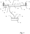
- Fig. 1 is a schematic side view of a stretching apparatus 10 according to an embodiment of the present invention.
- the apparatus 10 comprises an elongated bar 12.
- the bar 12 is straight or substantially straight. Further, the bar 12 is longitudinally or axially extendable.
- the bar 12 in turn includes an intermediate tube 14, a fixed member 18, and a moveable member 26.
- the fixed member 18 is rod-shaped and aligned with the tube 14.
- the hoop 22 is adjustable in length, so that hands or wrists of different sizes may be safely secured.
- the moveable member 26 At the opposite end 24 of the tube 14, there is provided the moveable member 26.
- the moveable member 26 is rod-shaped, and adapted to be moved longitudinally along or in alignment with the longitudinal axis 28 of the bar 12, at least partly entering the tube 14 and hence allowing extension of the bar 12.
- a second hoop 32 for securing the person's other hand or wrist to the moveable member 26 of the bar 12.
- the hoop 32 is adjustable in length, so that hands or wrists of different sizes may be safely secured.
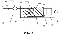
- a drive motor specifically an electric motor 34.
- the electric motor 34 may be powered by an internal battery (not shown). Alternatively, the electric motor 34 may be externally powered, e.g. via the mains supply.
- the electric motor 34 is mechanically connected via a clutch 36 to a rotatable sleeve 38 provided in the tube 14 towards the end 24.
- the electric motor 34 is adapted to rotate the sleeve 38 about the axis 28.
- the sleeve 38 is provided with an inner screw thread 40. Further, the moveable member 26 is opposite its far end 30 provided with a screw thread 42.
- the thread 42 is complementary to the inner thread 40 of the sleeve 38, and the moveable member 26 is partly screwed into the sleeve 38, whereby the member 26 kept non-rotating may be moved longitudinally or axially in relation to the rest of the bar 12 as indicated by the arrow 44 when the electric motor 34 is operated.
- the rotational motion of the motor 34 is transformed to linear motion (i.e. motion along a straight line) of the member 26.
- the moveable member 26 may for instance be provided with a tap engaged in a longitudinal groove of the tube 14.
- the clutch 36 is adapted to disconnect the electric motor 34, or making the electric motor 34 to "slip", when a force counteracting the extension or lengthening of the bar 12 reaches a particular value.
- the moveable member 26 may be retained in the position it holds when the particular value is reached.
- the clutch 36 may be adapted to allow rotation of the sleeve 38 in one direction only, i.e. the direction causing extension of the bar 12.
- a spring member (not shown) may be installed in the tube 14 for smoothing the operation of the moveable member 26 in particular at its end positions.
- the stretching apparatus 10 further comprises a control unit 46.
- the control unit 46 is operatively connected to the bar 12 via a cable 48. Alternatively, a wireless connection between the bar 12 and the unit 46 may be provided.
- the control unit 46 is designed to rest on a floor, while the bar 12 may be portable or non-stationary.
- On the upside 50 of the control unit 46 there is provided a first push button or pedal 52 and also a second push button or pedal 54. Operation of the first pedal 52 is designed to causes the bar 12 to be extended. Specifically, when the pedal 52 is pressed the electric motor 34 is initiated to rotate the sleeve 38 such that the moveable member 26 is screwed out of the sleeve 38 (towards the left in fig.
- the second pedal 54 is designed to release the bar 12 from an extended state. Specifically, when the pedal 54 is pressed the clutch 36 is deactivated or disengaged from the sleeve 38 allowing the moveable member 26 to be "pushed" back into the tube 14 by the counteracting force, causing the bar 12 to be retracted.
- the operating range of the bar 12, i.e. the minimum-maximum length of the bar 12, may be about 150-200 cm.
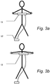
- the second pedal 54 is first pressed so that the bar 12 may be retracted to a suitable length somewhat shorter than the span of the arms of the person about to use the apparatus 10. Then, the person's first hand or wrist is secured to the bar 12 by means of one of the hoops, e.g. hoop 22, and the person's other hand or wrist is secured to the bar 12 by means of the other hoop 32, as illustrated in fig. 3a . Then, the person or user presses the first pedal 52 on the control unit 46, beneficially using his or hers foot. Operation of pedal 52 will cause the bar 12 to be longitudinally extended or lengthened.
- the lengthening of the bar 12 will pull the person's hands or wrists in opposite directions away from each other, stretching the muscles in the person's arms and torso.
- a force caused by the person's hands or wrists being attached to the bar 12 via the hoops 22, 32 will counteract or work against the bar 12 being extended.
- this counteracting force will reach the particular value defined above, whereby the clutch 36 disconnects the electric motor 34.
- the bar 12 may remain in this certain extended state ( fig. 3b ) until the person presses the second pedal 54 of the control unit 46 to release the bar 12 from this state.
- the member 18 could be moveable like the member 26.
- the sleeve 38 could be replaced by a screw and the moveable member 26 could be provided with a matching sleeve.
- the "clutch" may be included in the electric motor in that the motor is adapted to be disabled when the power needed to drive the motor exceeds a certain value.
- the buttons 52 and 54 could be finger operable switches located at one end of the bar.
- a vibrator (not shown) could be placed inside the bar, in order to supply the user with vibrations, which could enhance the effect of the stretching.
Landscapes
- Health & Medical Sciences (AREA)
- Animal Behavior & Ethology (AREA)
- Pain & Pain Management (AREA)
- Physical Education & Sports Medicine (AREA)
- Rehabilitation Therapy (AREA)
- Life Sciences & Earth Sciences (AREA)
- Epidemiology (AREA)
- General Health & Medical Sciences (AREA)
- Public Health (AREA)
- Veterinary Medicine (AREA)
- Rehabilitation Tools (AREA)
- Orthopedics, Nursing, And Contraception (AREA)
- Mutual Connection Of Rods And Tubes (AREA)
Claims (14)
- Streckvorrichtung (10) umfassend:eine in Längsrichtung erstreckbare Stange (12), die an jedem Ende (20, 30) mit einem Befestigungsmittel (22, 32) zur Befestigung der Hand oder des Handgelenks eines Benutzers an der Stange versehen ist, undeinen Antriebsmechanismus, die dafür eingerichtet ist, die Stange in Längsrichtung zu erstrecken.
- Streckvorrichtung nach Anspruch 1, wobei der Antriebsmechanismus dafür eingerichtet ist, die Stange zu erstrecken, bis eine entgegenwirkende Kraft einen bestimmten Wert erreicht.
- Streckvorrichtung nach Anspruch 1 oder 2, wobei der Antriebsmechanismus einen Antriebsmotor (34) zum Erstrecken der Stange umfasst.
- Streckvorrichtung nach Anspruch 3, wobei der Antriebsmechanismus weiter einen Kupplungsmechanismus (36) umfasst, welcher dafür eingerichtet ist, den Antriebsmotor zu unterbrechen oder auszuschalten, wenn die entgegenwirkende Kraft den bestimmten Wert erreicht.
- Streckvorrichtung nach einem der vorgehenden Ansprüche, wobei die Stange ein Stangenelement (26) umfasst, welches im Verhältnis zur restlichen Stange in Längsrichtung beweglich ist, wobei das Stangenelement mit einem der Befestigungsmittel versehen ist.
- Streckvorrichtung nach Anspruch 3 und 5, wobei der Antriebsmechanismus weiter Umwandlungsmittel (40, 42) zum Umformen der Rotationsbewegung des Antriebsmotors in eine lineare Bewegung des Stangenelements umfasst.
- Streckvorrichtung nach einem der vorgehenden Ansprüche, wobei der Antriebsmechanismus innerhalb der Stange angebracht ist.
- Streckvorrichtung nach einem der vorgehenden Ansprüche, wobei die Stange ein Hauptrohr (14), welches den Antriebsmechanismus enthält, und ein Rohr oder einen Stab (26) umfasst, das bzw. der teleskopisch angeordnet ist und sich von einem Ende des Hauptrohrs erstreckt.
- Streckvorrichtung nach einem der vorgehenden Ansprüche 1-7, wobei die Stange zwei teleskopisch angeordnete Rohre oder Stäbe umfasst.
- Streckvorrichtung nach einem der vorgehenden Ansprüche, wobei jedes der Befestigungsmittel ein Klettverschlussband umfasst.
- Streckvorrichtung nach einem der vorgehenden Ansprüche, weiter umfassend einen ersten Aktuator (52) zum Veranlassen von Erstreckung der Stange und einen zweiten Aktuator (54) zum Freigeben der Stange von dem Erstreckten Zustand.
- Streckvorrichtung nach Anspruch 11, weiter umfassend eine von der Stange getrennte Steuereinheit (46), wobei der erste und zweite Aktuator Pedale sind, die an der Steuereinheit vorgesehen sind.
- Streckvorrichtung nach Anspruch 11, wobei der erste und zweite Aktuator fingerbedienbare Schalter sind, die an einem oder verschiedenen Enden der Stange angeordnet sind.
- Streckvorrichtung nach einem der vorgehenden Ansprüche, weiter umfassend einen Vibrator, der in der Stange angebracht ist.
Applications Claiming Priority (2)
| Application Number | Priority Date | Filing Date | Title |
|---|---|---|---|
| NO20090034A NO329530B1 (no) | 2009-01-05 | 2009-01-05 | Strekkapparat |
| PCT/NO2010/000003 WO2010077153A1 (en) | 2009-01-05 | 2010-01-04 | Stretching apparatus |
Publications (3)
| Publication Number | Publication Date |
|---|---|
| EP2384183A1 EP2384183A1 (de) | 2011-11-09 |
| EP2384183A4 EP2384183A4 (de) | 2015-07-22 |
| EP2384183B1 true EP2384183B1 (de) | 2016-12-21 |
Family
ID=42309984
Family Applications (1)
| Application Number | Title | Priority Date | Filing Date |
|---|---|---|---|
| EP10726813.8A Not-in-force EP2384183B1 (de) | 2009-01-05 | 2010-01-04 | Streckvorrichtung |
Country Status (3)
| Country | Link |
|---|---|
| EP (1) | EP2384183B1 (de) |
| NO (1) | NO329530B1 (de) |
| WO (1) | WO2010077153A1 (de) |
Citations (1)
| Publication number | Priority date | Publication date | Assignee | Title |
|---|---|---|---|---|
| GB191106645A (en) * | 1911-03-16 | 1912-03-14 | Harry Ostrovsky | An Apparatus for use by Musicians for Promoting the Flexibility of the Joints and Stretching the Muscles and Ligaments of the Hands. |
Family Cites Families (6)
| Publication number | Priority date | Publication date | Assignee | Title |
|---|---|---|---|---|
| GB421216A (en) * | 1933-10-11 | 1934-12-17 | Jean Baptiste Toner | Device for developing freedom of movement of the hands |
| CH465764A (de) * | 1967-10-05 | 1968-11-30 | Zimmermann Hans | Hilfsgerät zur Beugung und Streckung der Wirbelsäule |
| FR1566287A (de) * | 1968-01-25 | 1969-05-09 | ||
| DE10214996B4 (de) * | 2002-04-05 | 2006-04-20 | Contex B.V. | Vorrichtung zur physiotherapeutischen Behandlung |
| US20050159683A1 (en) * | 2004-01-21 | 2005-07-21 | Hsin-Chih Kuo | Arm circulation system stretching, recuperative chest enlargement and respiration assistance apparatus |
| US7476182B2 (en) * | 2005-08-15 | 2009-01-13 | Denisco Christopher R | Horizontal hamstring stretcher |
-
2009
- 2009-01-05 NO NO20090034A patent/NO329530B1/no not_active IP Right Cessation
-
2010
- 2010-01-04 WO PCT/NO2010/000003 patent/WO2010077153A1/en not_active Ceased
- 2010-01-04 EP EP10726813.8A patent/EP2384183B1/de not_active Not-in-force
Patent Citations (1)
| Publication number | Priority date | Publication date | Assignee | Title |
|---|---|---|---|---|
| GB191106645A (en) * | 1911-03-16 | 1912-03-14 | Harry Ostrovsky | An Apparatus for use by Musicians for Promoting the Flexibility of the Joints and Stretching the Muscles and Ligaments of the Hands. |
Also Published As
| Publication number | Publication date |
|---|---|
| EP2384183A1 (de) | 2011-11-09 |
| NO329530B1 (no) | 2010-11-08 |
| EP2384183A4 (de) | 2015-07-22 |
| WO2010077153A1 (en) | 2010-07-08 |
| NO20090034L (no) | 2010-07-06 |
Similar Documents
| Publication | Publication Date | Title |
|---|---|---|
| US20240238106A1 (en) | Device for moving an arm and a method of operating a device | |
| EP3706702B1 (de) | Handexoskelettvorrichtung | |
| EP2525748B1 (de) | Einrichtung zur unterstützung der greiffunktion mit einer vorrichtung sowie einer befestigung der vorrichtung | |
| KR102562929B1 (ko) | 가요성 내시경용 제어 유닛 | |
| EP3414061B1 (de) | Vorrichtung zur verbesserung der greiffähigkeit eines benutzers | |
| NO176867B (no) | Håndbetjent vibrerende massasjeanordning | |
| JPWO2018055812A1 (ja) | 動作支援装置 | |
| DK177559B1 (en) | Aid grabbing tool with force activated gripping function | |
| US20130276844A1 (en) | Handle Assembly With Multi-Axial Adjustment | |
| US20140148918A1 (en) | Aid grabbing tool with hand operated gripper that can be pushed aside | |
| JP5687809B2 (ja) | 内視鏡処置具の進退補助具 | |
| WO2018156868A1 (en) | Medical inflation systems and methods | |
| JP2019527592A5 (de) | ||
| EP2384183A1 (de) | Streckvorrichtung | |
| EP3574882B1 (de) | Winde mit griff | |
| JP2009153607A (ja) | 運動補助装置 | |
| CN110074946B (zh) | 一种手腕功能康复训练装置 | |
| JP4446942B2 (ja) | 間接活線作業用絶縁操作棒 | |
| KR102572259B1 (ko) | 홀딩 컨트롤러 | |
| CN206623084U (zh) | 手部减压机械外骨骼装置的四指弯曲牵拉导向驱动系统 | |
| US20170020248A1 (en) | Devices, systems, and methods for combining mobility and reaching aids | |
| JP2005287116A (ja) | 押込補助具 | |
| CN115300330A (zh) | 采用连续柔性体驱动的手部灵巧康复机器人 | |
| JP6558647B2 (ja) | ブレーキ装置 | |
| TWI685333B (zh) | 手部物理復健裝置及其操作方法 |
Legal Events
| Date | Code | Title | Description |
|---|---|---|---|
| PUAI | Public reference made under article 153(3) epc to a published international application that has entered the european phase |
Free format text: ORIGINAL CODE: 0009012 |
|
| 17P | Request for examination filed |
Effective date: 20110802 |
|
| AK | Designated contracting states |
Kind code of ref document: A1 Designated state(s): AT BE BG CH CY CZ DE DK EE ES FI FR GB GR HR HU IE IS IT LI LT LU LV MC MK MT NL NO PL PT RO SE SI SK SM TR |
|
| DAX | Request for extension of the european patent (deleted) | ||
| RA4 | Supplementary search report drawn up and despatched (corrected) |
Effective date: 20150624 |
|
| RIC1 | Information provided on ipc code assigned before grant |
Ipc: A61H 23/02 20060101ALN20150618BHEP Ipc: A61H 1/02 20060101AFI20150618BHEP |
|
| GRAP | Despatch of communication of intention to grant a patent |
Free format text: ORIGINAL CODE: EPIDOSNIGR1 |
|
| RIC1 | Information provided on ipc code assigned before grant |
Ipc: A61H 1/02 20060101AFI20160608BHEP Ipc: A61H 23/02 20060101ALN20160608BHEP |
|
| RIC1 | Information provided on ipc code assigned before grant |
Ipc: A61H 23/02 20060101ALN20160630BHEP Ipc: A61H 1/02 20060101AFI20160630BHEP |
|
| INTG | Intention to grant announced |
Effective date: 20160713 |
|
| GRAS | Grant fee paid |
Free format text: ORIGINAL CODE: EPIDOSNIGR3 |
|
| GRAA | (expected) grant |
Free format text: ORIGINAL CODE: 0009210 |
|
| AK | Designated contracting states |
Kind code of ref document: B1 Designated state(s): AT BE BG CH CY CZ DE DK EE ES FI FR GB GR HR HU IE IS IT LI LT LU LV MC MK MT NL NO PL PT RO SE SI SK SM TR |
|
| REG | Reference to a national code |
Ref country code: GB Ref legal event code: FG4D |
|
| REG | Reference to a national code |
Ref country code: CH Ref legal event code: EP |
|
| REG | Reference to a national code |
Ref country code: IE Ref legal event code: FG4D |
|
| REG | Reference to a national code |
Ref country code: AT Ref legal event code: REF Ref document number: 854836 Country of ref document: AT Kind code of ref document: T Effective date: 20170115 |
|
| REG | Reference to a national code |
Ref country code: DE Ref legal event code: R096 Ref document number: 602010038965 Country of ref document: DE |
|
| PG25 | Lapsed in a contracting state [announced via postgrant information from national office to epo] |
Ref country code: LV Free format text: LAPSE BECAUSE OF FAILURE TO SUBMIT A TRANSLATION OF THE DESCRIPTION OR TO PAY THE FEE WITHIN THE PRESCRIBED TIME-LIMIT Effective date: 20161221 |
|
| REG | Reference to a national code |
Ref country code: LT Ref legal event code: MG4D |
|
| REG | Reference to a national code |
Ref country code: NL Ref legal event code: MP Effective date: 20161221 |
|
| PG25 | Lapsed in a contracting state [announced via postgrant information from national office to epo] |
Ref country code: NO Free format text: LAPSE BECAUSE OF FAILURE TO SUBMIT A TRANSLATION OF THE DESCRIPTION OR TO PAY THE FEE WITHIN THE PRESCRIBED TIME-LIMIT Effective date: 20170321 Ref country code: GR Free format text: LAPSE BECAUSE OF FAILURE TO SUBMIT A TRANSLATION OF THE DESCRIPTION OR TO PAY THE FEE WITHIN THE PRESCRIBED TIME-LIMIT Effective date: 20170322 Ref country code: SE Free format text: LAPSE BECAUSE OF FAILURE TO SUBMIT A TRANSLATION OF THE DESCRIPTION OR TO PAY THE FEE WITHIN THE PRESCRIBED TIME-LIMIT Effective date: 20161221 Ref country code: LT Free format text: LAPSE BECAUSE OF FAILURE TO SUBMIT A TRANSLATION OF THE DESCRIPTION OR TO PAY THE FEE WITHIN THE PRESCRIBED TIME-LIMIT Effective date: 20161221 |
|
| REG | Reference to a national code |
Ref country code: AT Ref legal event code: MK05 Ref document number: 854836 Country of ref document: AT Kind code of ref document: T Effective date: 20161221 |
|
| PG25 | Lapsed in a contracting state [announced via postgrant information from national office to epo] |
Ref country code: FI Free format text: LAPSE BECAUSE OF FAILURE TO SUBMIT A TRANSLATION OF THE DESCRIPTION OR TO PAY THE FEE WITHIN THE PRESCRIBED TIME-LIMIT Effective date: 20161221 Ref country code: HR Free format text: LAPSE BECAUSE OF FAILURE TO SUBMIT A TRANSLATION OF THE DESCRIPTION OR TO PAY THE FEE WITHIN THE PRESCRIBED TIME-LIMIT Effective date: 20161221 Ref country code: BE Free format text: LAPSE BECAUSE OF NON-PAYMENT OF DUE FEES Effective date: 20170131 |
|
| PG25 | Lapsed in a contracting state [announced via postgrant information from national office to epo] |
Ref country code: NL Free format text: LAPSE BECAUSE OF FAILURE TO SUBMIT A TRANSLATION OF THE DESCRIPTION OR TO PAY THE FEE WITHIN THE PRESCRIBED TIME-LIMIT Effective date: 20161221 |
|
| PG25 | Lapsed in a contracting state [announced via postgrant information from national office to epo] |
Ref country code: IS Free format text: LAPSE BECAUSE OF FAILURE TO SUBMIT A TRANSLATION OF THE DESCRIPTION OR TO PAY THE FEE WITHIN THE PRESCRIBED TIME-LIMIT Effective date: 20170421 Ref country code: EE Free format text: LAPSE BECAUSE OF FAILURE TO SUBMIT A TRANSLATION OF THE DESCRIPTION OR TO PAY THE FEE WITHIN THE PRESCRIBED TIME-LIMIT Effective date: 20161221 Ref country code: SK Free format text: LAPSE BECAUSE OF FAILURE TO SUBMIT A TRANSLATION OF THE DESCRIPTION OR TO PAY THE FEE WITHIN THE PRESCRIBED TIME-LIMIT Effective date: 20161221 Ref country code: RO Free format text: LAPSE BECAUSE OF FAILURE TO SUBMIT A TRANSLATION OF THE DESCRIPTION OR TO PAY THE FEE WITHIN THE PRESCRIBED TIME-LIMIT Effective date: 20161221 Ref country code: CZ Free format text: LAPSE BECAUSE OF FAILURE TO SUBMIT A TRANSLATION OF THE DESCRIPTION OR TO PAY THE FEE WITHIN THE PRESCRIBED TIME-LIMIT Effective date: 20161221 |
|
| REG | Reference to a national code |
Ref country code: DE Ref legal event code: R119 Ref document number: 602010038965 Country of ref document: DE |
|
| PG25 | Lapsed in a contracting state [announced via postgrant information from national office to epo] |
Ref country code: BG Free format text: LAPSE BECAUSE OF FAILURE TO SUBMIT A TRANSLATION OF THE DESCRIPTION OR TO PAY THE FEE WITHIN THE PRESCRIBED TIME-LIMIT Effective date: 20170321 Ref country code: PT Free format text: LAPSE BECAUSE OF FAILURE TO SUBMIT A TRANSLATION OF THE DESCRIPTION OR TO PAY THE FEE WITHIN THE PRESCRIBED TIME-LIMIT Effective date: 20170421 Ref country code: PL Free format text: LAPSE BECAUSE OF FAILURE TO SUBMIT A TRANSLATION OF THE DESCRIPTION OR TO PAY THE FEE WITHIN THE PRESCRIBED TIME-LIMIT Effective date: 20161221 Ref country code: IT Free format text: LAPSE BECAUSE OF FAILURE TO SUBMIT A TRANSLATION OF THE DESCRIPTION OR TO PAY THE FEE WITHIN THE PRESCRIBED TIME-LIMIT Effective date: 20161221 Ref country code: ES Free format text: LAPSE BECAUSE OF FAILURE TO SUBMIT A TRANSLATION OF THE DESCRIPTION OR TO PAY THE FEE WITHIN THE PRESCRIBED TIME-LIMIT Effective date: 20161221 Ref country code: BE Free format text: LAPSE BECAUSE OF FAILURE TO SUBMIT A TRANSLATION OF THE DESCRIPTION OR TO PAY THE FEE WITHIN THE PRESCRIBED TIME-LIMIT Effective date: 20161221 Ref country code: SM Free format text: LAPSE BECAUSE OF FAILURE TO SUBMIT A TRANSLATION OF THE DESCRIPTION OR TO PAY THE FEE WITHIN THE PRESCRIBED TIME-LIMIT Effective date: 20161221 Ref country code: AT Free format text: LAPSE BECAUSE OF FAILURE TO SUBMIT A TRANSLATION OF THE DESCRIPTION OR TO PAY THE FEE WITHIN THE PRESCRIBED TIME-LIMIT Effective date: 20161221 |
|
| REG | Reference to a national code |
Ref country code: CH Ref legal event code: PL |
|
| PG25 | Lapsed in a contracting state [announced via postgrant information from national office to epo] |
Ref country code: MC Free format text: LAPSE BECAUSE OF FAILURE TO SUBMIT A TRANSLATION OF THE DESCRIPTION OR TO PAY THE FEE WITHIN THE PRESCRIBED TIME-LIMIT Effective date: 20161221 |
|
| PLBE | No opposition filed within time limit |
Free format text: ORIGINAL CODE: 0009261 |
|
| REG | Reference to a national code |
Ref country code: FR Ref legal event code: ST Effective date: 20170929 |
|
| STAA | Information on the status of an ep patent application or granted ep patent |
Free format text: STATUS: NO OPPOSITION FILED WITHIN TIME LIMIT |
|
| PG25 | Lapsed in a contracting state [announced via postgrant information from national office to epo] |
Ref country code: FR Free format text: LAPSE BECAUSE OF NON-PAYMENT OF DUE FEES Effective date: 20170221 Ref country code: CH Free format text: LAPSE BECAUSE OF NON-PAYMENT OF DUE FEES Effective date: 20170131 Ref country code: LI Free format text: LAPSE BECAUSE OF NON-PAYMENT OF DUE FEES Effective date: 20170131 |
|
| REG | Reference to a national code |
Ref country code: IE Ref legal event code: MM4A |
|
| 26N | No opposition filed |
Effective date: 20170922 |
|
| GBPC | Gb: european patent ceased through non-payment of renewal fee |
Effective date: 20170321 |
|
| PG25 | Lapsed in a contracting state [announced via postgrant information from national office to epo] |
Ref country code: DK Free format text: LAPSE BECAUSE OF FAILURE TO SUBMIT A TRANSLATION OF THE DESCRIPTION OR TO PAY THE FEE WITHIN THE PRESCRIBED TIME-LIMIT Effective date: 20161221 Ref country code: LU Free format text: LAPSE BECAUSE OF NON-PAYMENT OF DUE FEES Effective date: 20170104 Ref country code: DE Free format text: LAPSE BECAUSE OF NON-PAYMENT OF DUE FEES Effective date: 20170801 |
|
| PG25 | Lapsed in a contracting state [announced via postgrant information from national office to epo] |
Ref country code: GB Free format text: LAPSE BECAUSE OF NON-PAYMENT OF DUE FEES Effective date: 20170321 Ref country code: IE Free format text: LAPSE BECAUSE OF NON-PAYMENT OF DUE FEES Effective date: 20170104 Ref country code: SI Free format text: LAPSE BECAUSE OF FAILURE TO SUBMIT A TRANSLATION OF THE DESCRIPTION OR TO PAY THE FEE WITHIN THE PRESCRIBED TIME-LIMIT Effective date: 20161221 |
|
| PG25 | Lapsed in a contracting state [announced via postgrant information from national office to epo] |
Ref country code: MT Free format text: LAPSE BECAUSE OF NON-PAYMENT OF DUE FEES Effective date: 20170104 |
|
| PG25 | Lapsed in a contracting state [announced via postgrant information from national office to epo] |
Ref country code: HU Free format text: LAPSE BECAUSE OF FAILURE TO SUBMIT A TRANSLATION OF THE DESCRIPTION OR TO PAY THE FEE WITHIN THE PRESCRIBED TIME-LIMIT; INVALID AB INITIO Effective date: 20100104 |
|
| PG25 | Lapsed in a contracting state [announced via postgrant information from national office to epo] |
Ref country code: CY Free format text: LAPSE BECAUSE OF NON-PAYMENT OF DUE FEES Effective date: 20161221 |
|
| PG25 | Lapsed in a contracting state [announced via postgrant information from national office to epo] |
Ref country code: MK Free format text: LAPSE BECAUSE OF FAILURE TO SUBMIT A TRANSLATION OF THE DESCRIPTION OR TO PAY THE FEE WITHIN THE PRESCRIBED TIME-LIMIT Effective date: 20161221 |
|
| PG25 | Lapsed in a contracting state [announced via postgrant information from national office to epo] |
Ref country code: TR Free format text: LAPSE BECAUSE OF FAILURE TO SUBMIT A TRANSLATION OF THE DESCRIPTION OR TO PAY THE FEE WITHIN THE PRESCRIBED TIME-LIMIT Effective date: 20161221 |