EP2385185A1 - Support d'élément de façade et procédé de fabrication d'un support d'élément de façade - Google Patents
Support d'élément de façade et procédé de fabrication d'un support d'élément de façade Download PDFInfo
- Publication number
- EP2385185A1 EP2385185A1 EP10162111A EP10162111A EP2385185A1 EP 2385185 A1 EP2385185 A1 EP 2385185A1 EP 10162111 A EP10162111 A EP 10162111A EP 10162111 A EP10162111 A EP 10162111A EP 2385185 A1 EP2385185 A1 EP 2385185A1
- Authority
- EP
- European Patent Office
- Prior art keywords
- holder
- facade element
- holder portion
- section
- flat material
- Prior art date
- Legal status (The legal status is an assumption and is not a legal conclusion. Google has not performed a legal analysis and makes no representation as to the accuracy of the status listed.)
- Withdrawn
Links
Images


Classifications
-
- E—FIXED CONSTRUCTIONS
- E04—BUILDING
- E04F—FINISHING WORK ON BUILDINGS, e.g. STAIRS, FLOORS
- E04F13/00—Coverings or linings, e.g. for walls or ceilings
- E04F13/07—Coverings or linings, e.g. for walls or ceilings composed of covering or lining elements; Sub-structures therefor; Fastening means therefor
- E04F13/08—Coverings or linings, e.g. for walls or ceilings composed of covering or lining elements; Sub-structures therefor; Fastening means therefor composed of a plurality of similar covering or lining elements
- E04F13/0801—Separate fastening elements
- E04F13/0803—Separate fastening elements with load-supporting elongated furring elements between wall and covering elements
- E04F13/0805—Separate fastening elements with load-supporting elongated furring elements between wall and covering elements with additional fastening elements between furring elements and the wall
Definitions
- the invention relates to a facade element holder, comprising a holder made of a flat material with a first holder portion for attachment to a wall and with an angle to the first holder portion arranged second holder portion for the direct or indirect attachment of a facade element.
- Such a facade element holder is from the DE 199 45 886 C1 known.
- This facade element holder is designed in the form of a mounting bracket, wherein the first holder portion of the mounting bracket can be fastened to a building wall and wherein the second holder portion arranged at an angle to the first holder portion serves for fastening a holder profile, to which in turn facade elements can be fastened.
- the present invention seeks to provide a particularly easy to assemble facade element holder.
- first holder section and the second holder section are connected to one another by means of a first connecting section, in which the flat material has a lower material thickness compared to the material thicknesses of the holder sections and / or is deformed in this way, in that the first connecting portion forms a first bending edge, which is an adjustment of a first Knickwinkels the second holder portion relative to the first holder portion allows.
- the facade element holder according to the invention allows a relative movement of the second holder portion relative to the first holder portion, wherein the position of the second holder portion is adjustable about a bending edge relative to the first holder portion.
- the buckling edge is provided in the region of a connecting section in which the flat material from which the facade element holder is made is weakened and / or reshaped. So there are no additional hinges or the like provided, which would complicate the construction of the facade element holder and would greatly increase the cost.
- the facade element holder according to the invention enables a simple and flexible installation.
- the mobility of the second holder portion relative to the first holder portion has the advantage that the fixation of the first holder portion is facilitated on a masonry, since fasteners used for this purpose, such as screws, are more accessible and even with large projections of the second holder portion no overlong tools are required ,
- the first holder portion can also be mounted deviating from an optimal position, and it can be compensated thereby dimensional deviations by adjusting the first bending angle.
- the relative movability of the holder portions makes it possible to transport the facade element holder in a state in which the relative position of the holder portions deviates from the relative position of the holder portions in a completely assembled facade element holder. In this way, the packing size of the facade element holder can be reduced.
- the flat material is single-layered and, for example, is made exclusively of a stainless steel material, in particular with a material thickness of, for example, between about 2 mm to about 5 mm.
- the flat material is multi-layered.
- Such a flat material has a sandwich construction. It is possible that the layers of the multilayer sheet are made of the same material, but the individual layers have a different geometry, for example using a plate-shaped first layer and a honeycomb second layer, both of the same material, for example aluminum or stainless steel are made.
- a multilayer sheet have layers made of mutually different materials. It is particularly preferred if the flat material comprises at least one first metallic layer and at least one non-metallic layer.
- the metallic layer is preferably stainless steel, which can reduce undesirable heat flow compared to aluminum.
- the non-metallic layer is, for example, a plastic material, for example polyethylene. Such a material has sufficient mechanical properties and acts as a heat insulator.
- the use of a non-metallic layer makes it possible to reduce the weight of the facade element. Overall, a very stable, lightweight and heat-insulating facade element holder can be created.
- the flat material comprises a second metallic layer and that the non-metallic layer is arranged between the first metallic layer and the second metallic layer.
- a material is known, for example, under the name "Alucobond”, which is offered by the company “3A Composites GmbH” in Singen, Germany. Further, such a material is known as “Alpolic” by Mitsubishi Plastics Composites America, Inc. This is a three-ply material with two outer layers of aluminum and a core layer of a mineral, fire-resistant material.
- a metallic layer arranged on the inner side of the connecting edge is completely perforated in the region of the connecting section and the core material is at least partially weakened, so that on the one hand the facade element holder has sufficient stability in the region of the connecting section and on the other hand, the second holder portion relative to the first holder portion to the bending edge is movable, without the need for excessive adjustment forces would be required.
- the forces required to deform the buckling edge are applied by hand and are maximum for example between about 10 N and about 100 N.
- the holder has a third holder portion, which is connected by means of a second connecting portion which forms a second bending edge, with the first holder portion, wherein the second bending edge setting a second bending angle of the third holder portion relative to the first holder section allows.
- a facade element holder makes it possible, for example, to easily produce a U-profile in which the second holder portion and the third holder portion protrude in the assembled state of the facade element holder of a building wall and are used for direct or indirect attachment of facade elements.
- the distance between the second holder portion and the third holder portion in the region of the first holder portion facing away from the free end can be adjusted simultaneously.
- the first connecting portion and / or the second connecting portion preferably has a notch worked into the flat material.
- the flat material may for example be embossed with a stamping tool or stamp, if necessary using a counter-holder; or material is removed, for example by milling.
- the second holder section and the third holder section can be connected to one another or connected to one another by means of a connecting device.
- a connecting device In this way, it is possible to provide a triangular body whose triangular sides are each formed by one of the holder sections.
- Such a body has a very high deformation stability, in particular a very high buckling stiffness about a perpendicular to the first bending edge and / or the second bending edge extending reference axis.
- the second holder section and the third holder section can be connected to one another in at least two mutually different combinations of the first articulation angle and the second articulation angle.
- these protrude so to speak in the form of an assembly, from the first holder portion.
- the second holder portion and / or the third holder portion has or have at least one elongated hole, which is enforced by a connecting element or interspersed. This allows easy connection of the second holder portion and the third holder section for different combinations of first kink angle and second kink angle.
- the invention further relates to a method for producing a facade element holder from a flat material.
- the present invention has the further object of specifying a method which allows the production of a particularly easy to assemble facade element holder.
- This object is achieved in a method mentioned above according to the invention that the flat material is deformed and / or that a material thickness of the sheet is reduced so that it is smaller than the material thicknesses of a first holder portion adjacent to the first connecting portion for attachment on a wall and a second holder portion adjoining the first connection portion for indirectly or directly attaching a facade element, and that the first connection portion is used as a first bending edge to set a first bending angle of the second holder portion relative to the first holder portion.
- the method according to the invention can, if required, be carried out on site, i. H. be carried out directly at the place of installation of the facade element holder.
- a flat sheet material is provided, which is weakened by embossing or milling, so that a bent edge is formed.
- the position of the connecting portion in principle is arbitrary, so that in principle for any mounting requirements correspondingly dimensioned facade element holder can be made.
- connecting portions are prefabricated, and that only the adjustment of the bending angle is performed at the site of assembly of the facade element.
- the invention further relates to the use of a flat material described above for carrying out a method described above.
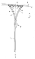
- An embodiment of a facade element holder 10 has a one-piece holder 12, which comprises a plurality of holder sections.
- the holder 12 comprises a first holder section 14, which serves for fastening the facade element holder 10 to a wall 16 shown in sections.
- the holder 12 further includes a second holder portion 18 and a third holder portion 20.
- the holder portions 18 and 20 are disposed on opposite sides of the first holder portion 14.
- the second holder portion 18 is connected to the first holder portion 14 by means of a connecting portion 22.
- the third holder portion 20 is connected to the first holder portion 14 by means of a second connecting portion 24.
- the first connecting portion 22 and the second connecting portion 24 each have a groove 26 or 28 incorporated in the flat material of the holder 12.
- the notches 26 and 28 extend vertically in an assembled state of the facade element holder 10, preferably with respect to the direction of gravity.
- a first bending axis 30 is defined.
- a second bending axis 32 is defined.
- the first bending axis 30 and the second bending axis 32 are parallel to each other.
- the layer structure of the sheet material from which the holder 12 is made is made of FIG. 2a good to see.
- the flat material is multi-layered and has a first, metallic layer 34 and a second metallic layer 36.
- the metallic layers 34 and 36 are preferably made of made of a stainless material and have a layer thickness of, for example, between about 0.2 mm and about 0.5 mm.
- a non-metallic layer 38 is arranged, which forms the core of the sheet.
- the layer thickness of the layer 38 is for example between about 2 mm and about 5 mm.
- the flat material In the region of the first holder section 14 and in the region of the second holder section 18 and in the region of the third holder section 20, the flat material has a material thickness 40 of, for example, between approximately 2.4 mm and approximately 6 mm. In the region of the first connection section 22 and also in the region of the second connection section 24, this material thickness 40 is reduced. In the connecting section 22, the flat material has a material thickness 42 of, for example, between about 0.2 mm and about 2 mm.
- the notch 26 and 28 is so deep that it completely breaks through the material of one of the metallic layers 34, 36 and the material of the intermediate layer 38 at least partially weakens.
- inner surfaces 44 and 46 which are formed by one of the metallic layers, for example by the second metallic layer 36, separated from each other.
- the outer surfaces 48 and 50 of different holder parts 14 and 18, 20 in the region of a metallic outer layer 34 are interconnected.
- an alternative usable facade element holder 10 are the Inner surfaces 44 and 46, which are formed by one of the metallic layers, for example by the second metallic layer 36, connected to each other.
- the notch 26 or 28 of the connecting portion 22 and 24 is only so deep that one of the metallic layers, for example, the first metallic layer 34, in a non-kinked state of the facade element holder 10 is undeformed and level.
- Such a connecting portion can be produced for example by means of a stamping tool and using a flat counter-holder.
- the inner surfaces 44 and 46 which are formed by one of the metallic layers, for example by the second metallic layer 36, also connected to each other.
- the notch 26 or 28 of the connecting portion 22 and 24 is formed so that all layers of the sheet are deformed, but without reducing the material thickness 40 of the sheet.
- Such a connecting section can be produced, for example, by means of an embossing tool and using a counter-holder having a die.
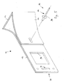
- the first holder section has a first fastening section 52, in particular in the form of an opening 54.
- the aperture 54 is preferably slot-shaped and penetrated by a fastener 56 or sougreifbar.
- the fastening element 56 is, for example, a screw which is secured against slipping through the aperture 54 by means of a washer 58. The screw 56 engages in an anchored in the masonry of the wall 16 dowels.
- the second holder section 18 has, in a region spaced from the first connecting section 22, a second fastening section 60 in the form of a slot 62.
- the third holder portion 20 has a corresponding third attachment portion 64 in the form of a slot 66.
- the slot axes of the slots 62 and 66 extend perpendicular to the buckling axes 30 and 32.
- the slots 62 and 66 have, for example, the same distance to the respective adjacent connecting portion 22 and 24 respectively.
- the second holder portion 18 has a free end 68, on which at least one further attachment portion 70 is provided, which is formed for example in the form of an opening 72.
- the at least one further attachment portion 70 is used for attachment of a facade element, not shown, or further, not shown components or component groups, which are connectable or connected to a facade element.
- the second holder portion 18 and the third holder portion 20 can be pivoted so far about the bending axes 30 and 32 that the inner surface 46 of the second holder portion 18 and an inner surface 78 of third holder portion 20 abut each other.
- the position of the elongated holes 62 and 66 is chosen so that they are flush with each other when the inner surfaces 46 and 78.
- This makes it possible to guide a connecting element 80 of a connecting device 82 through the perforations 62 and 66 in order to connect the holder sections 18 and 20 to one another.
- the connecting device 82 preferably comprises a lock nut 84 and optionally a washer 86.
- a holder axis 88 is defined which extends at an angle to the first holder section 14, in particular vertically.
- the free end 68 of the second holder portion 18 can be pivoted in a first pivoting direction 90.
- the free end 68 of the second holder portion 18 is pivoted in the opposite direction of pivoting 92. In this way, the angle between the holder axis 88 and the first holder portion 14 can be adjusted.
- a fixation of the holder portions 18 and 20 relative to each other is possible, thanks to the slots 62 and 66, in different pivotal positions.
- the pivotability described above also makes it possible to compensate for a tendency of an outer surface of the wall 16. This is for two differently inclined walls 16 in FIG. 4 shown schematically.
- the holder axis 88 extends relative to the holder portion 14 in the middle. However, it is also possible that the holder axis 88 is offset relative to a center of the first holder portion 14. A maximum offset results when the holder axis 88 intersects one of the bending axes 30 or 32.
- the holder portions 18 and 20 are curved in an area adjacent to the first holder portion 14. This has the advantage that after installation of the facade element holder 10 on a wall 16 of the outside of the holder sections 18 and 20 adjacent space can be filled in a simple manner with thermal insulation material, which is guided on the curved outer surfaces 50 and 94 and when approaching the Wall 16 is gently crushed.
- FIG. 5 illustrated embodiment of a facade element holder 10 has a structure similar to the facade element holder described above.
- the peculiarity of the facade element holder 10 according to FIG. 5 is that it has a further opening 96, whose function is to minimize heat flow between the free end 68 and the first holder portion 14.
- the connecting element 80 may also be a rivet 98, for example.
Landscapes
- Engineering & Computer Science (AREA)
- Architecture (AREA)
- Civil Engineering (AREA)
- Structural Engineering (AREA)
- Finishing Walls (AREA)
Priority Applications (1)
| Application Number | Priority Date | Filing Date | Title |
|---|---|---|---|
| EP10162111A EP2385185A1 (fr) | 2010-05-06 | 2010-05-06 | Support d'élément de façade et procédé de fabrication d'un support d'élément de façade |
Applications Claiming Priority (1)
| Application Number | Priority Date | Filing Date | Title |
|---|---|---|---|
| EP10162111A EP2385185A1 (fr) | 2010-05-06 | 2010-05-06 | Support d'élément de façade et procédé de fabrication d'un support d'élément de façade |
Publications (1)
| Publication Number | Publication Date |
|---|---|
| EP2385185A1 true EP2385185A1 (fr) | 2011-11-09 |
Family
ID=43334659
Family Applications (1)
| Application Number | Title | Priority Date | Filing Date |
|---|---|---|---|
| EP10162111A Withdrawn EP2385185A1 (fr) | 2010-05-06 | 2010-05-06 | Support d'élément de façade et procédé de fabrication d'un support d'élément de façade |
Country Status (1)
| Country | Link |
|---|---|
| EP (1) | EP2385185A1 (fr) |
Cited By (1)
| Publication number | Priority date | Publication date | Assignee | Title |
|---|---|---|---|---|
| EP2647779A1 (fr) * | 2012-04-05 | 2013-10-09 | Sto Ag | Support d'angle pour une infrastructure de façade |
Citations (7)
| Publication number | Priority date | Publication date | Assignee | Title |
|---|---|---|---|---|
| WO1982003574A1 (fr) * | 1981-04-13 | 1982-10-28 | Stroemberg Jan | Procede de pliage |
| FR2514391A1 (fr) * | 1981-06-30 | 1983-04-15 | Angers Ardoisieres | Dispositif pour fixer a distance d'un mur, un habillage constitue de plaques juxtaposees |
| FR2677411A1 (fr) * | 1991-06-04 | 1992-12-11 | Saint Gobain Isover | Systeme pour la fixation de produits isolants. |
| DE29502598U1 (de) * | 1995-02-17 | 1995-04-06 | Hünting, Harald, Dipl.-Ing., 97332 Volkach | Vorrichtung zur Befestigung einer Strebe an einem Rohbauuntergrund |
| DE19653672A1 (de) * | 1996-12-12 | 1998-06-25 | Robert Dipl Ing Berger | Vorrichtung zum Befestigen einer hinterlüfteten Außenwandbekleidung |
| WO2004028937A2 (fr) * | 2002-09-26 | 2004-04-08 | Industrial Origami, Llc | Techniques permettant de concevoir et de fabriquer avec precision des structures cintrees a resistance elevee et resistant a la fatigue, et feuille obtenue a l'aide de ces techniques |
| DE202004008656U1 (de) * | 2004-06-01 | 2004-12-09 | Knoll, Stefan | Direktabhänger zum Befestigen von CD-Profilen oder Holzlatten im Trockenbau bzw. Innenausbau durch verschiedenste Gewerke |
-
2010
- 2010-05-06 EP EP10162111A patent/EP2385185A1/fr not_active Withdrawn
Patent Citations (7)
| Publication number | Priority date | Publication date | Assignee | Title |
|---|---|---|---|---|
| WO1982003574A1 (fr) * | 1981-04-13 | 1982-10-28 | Stroemberg Jan | Procede de pliage |
| FR2514391A1 (fr) * | 1981-06-30 | 1983-04-15 | Angers Ardoisieres | Dispositif pour fixer a distance d'un mur, un habillage constitue de plaques juxtaposees |
| FR2677411A1 (fr) * | 1991-06-04 | 1992-12-11 | Saint Gobain Isover | Systeme pour la fixation de produits isolants. |
| DE29502598U1 (de) * | 1995-02-17 | 1995-04-06 | Hünting, Harald, Dipl.-Ing., 97332 Volkach | Vorrichtung zur Befestigung einer Strebe an einem Rohbauuntergrund |
| DE19653672A1 (de) * | 1996-12-12 | 1998-06-25 | Robert Dipl Ing Berger | Vorrichtung zum Befestigen einer hinterlüfteten Außenwandbekleidung |
| WO2004028937A2 (fr) * | 2002-09-26 | 2004-04-08 | Industrial Origami, Llc | Techniques permettant de concevoir et de fabriquer avec precision des structures cintrees a resistance elevee et resistant a la fatigue, et feuille obtenue a l'aide de ces techniques |
| DE202004008656U1 (de) * | 2004-06-01 | 2004-12-09 | Knoll, Stefan | Direktabhänger zum Befestigen von CD-Profilen oder Holzlatten im Trockenbau bzw. Innenausbau durch verschiedenste Gewerke |
Cited By (1)
| Publication number | Priority date | Publication date | Assignee | Title |
|---|---|---|---|---|
| EP2647779A1 (fr) * | 2012-04-05 | 2013-10-09 | Sto Ag | Support d'angle pour une infrastructure de façade |
Similar Documents
| Publication | Publication Date | Title |
|---|---|---|
| DE112015001441B4 (de) | Fahrzeugenergie-Absorptionsstruktur und Energieabsorptionselement | |
| DE102009030635B4 (de) | Haltewinkel für ein Fassadensystem | |
| EP3325735B1 (fr) | Façade pour un batiment, montee a partir d'elements composites | |
| DE102009008720A1 (de) | Verbindungselement | |
| DE102005016175A1 (de) | C-Profil | |
| DE1455813A1 (de) | Formteile mit gepressten Rippen und verstaerkten Verbindungsstellen | |
| DE10259307A1 (de) | Flächiges Metallelement und Profilelement | |
| EP2589725B1 (fr) | Élément de liaison et système de profil d'aération pour façades de bâtiments ventilées à l'arrière | |
| EP2468495B1 (fr) | Plaque en sandwich renforcée sur la zone périphérique, élément de renforcement et procédé de fabrication d'une plaque en sandwich renforcée sur la zone périphérique | |
| EP3545210B1 (fr) | Agencement d'amortissement et de ressort et son procédé de fabrication | |
| DE102008021224B4 (de) | Schienenfahrzeug | |
| EP1866492B1 (fr) | Profile en c et cloison de séparation à profile en c | |
| DE202008000534U1 (de) | Profilschienensystem zum Abdecken mindestens eines Belagrandes | |
| EP3199824A1 (fr) | Système de fixation et son utilisation | |
| EP0919674A1 (fr) | Element support | |
| DE102007007620A1 (de) | Wand- oder Deckenverkleidung | |
| EP3620603A1 (fr) | Système de montage pour murs | |
| DE2744757A1 (de) | Verfahren zur anbringung von lageraugen an schwenkbar zu lagernden konstruktionsteilen, insbesondere scharnierfluegeln | |
| DE202018103083U1 (de) | Befestigungssystem mit Kraftverteilung | |
| EP3788210B1 (fr) | Système d'ancrage à force transversale | |
| EP4074917B1 (fr) | Montage d'une structure de protection contre les chutes à un cadre au moyen d'un corps de fixation sans connexion directe à un dispositif de fixation de cadre | |
| EP2912970B1 (fr) | Panneau de construction léger ainsi que son procédé de fabrication | |
| EP3593987A1 (fr) | Composant acoustique | |
| DE102024120746A1 (de) | Paneel, Verfahren zum Montieren einer Montagestruktur an einem Paneel und ein Verfahren zum Bereitstellen eines Befestigungsbereichs in einem Paneel | |
| EP2602398B1 (fr) | Cadre en bois |
Legal Events
| Date | Code | Title | Description |
|---|---|---|---|
| AK | Designated contracting states |
Kind code of ref document: A1 Designated state(s): AL AT BE BG CH CY CZ DE DK EE ES FI FR GB GR HR HU IE IS IT LI LT LU LV MC MK MT NL NO PL PT RO SE SI SK SM TR |
|
| AX | Request for extension of the european patent |
Extension state: BA ME RS |
|
| PUAI | Public reference made under article 153(3) epc to a published international application that has entered the european phase |
Free format text: ORIGINAL CODE: 0009012 |
|
| STAA | Information on the status of an ep patent application or granted ep patent |
Free format text: STATUS: THE APPLICATION IS DEEMED TO BE WITHDRAWN |
|
| 18D | Application deemed to be withdrawn |
Effective date: 20120510 |