EP2385209A2 - Dispositif de réglage de l'inclinaison d'un vantail - Google Patents
Dispositif de réglage de l'inclinaison d'un vantail Download PDFInfo
- Publication number
- EP2385209A2 EP2385209A2 EP11450057A EP11450057A EP2385209A2 EP 2385209 A2 EP2385209 A2 EP 2385209A2 EP 11450057 A EP11450057 A EP 11450057A EP 11450057 A EP11450057 A EP 11450057A EP 2385209 A2 EP2385209 A2 EP 2385209A2
- Authority
- EP
- European Patent Office
- Prior art keywords
- door leaf
- shaft
- end parts
- recess
- worm
- Prior art date
- Legal status (The legal status is an assumption and is not a legal conclusion. Google has not performed a legal analysis and makes no representation as to the accuracy of the status listed.)
- Granted
Links
Images


Classifications
-
- E—FIXED CONSTRUCTIONS
- E04—BUILDING
- E04F—FINISHING WORK ON BUILDINGS, e.g. STAIRS, FLOORS
- E04F21/00—Implements for finishing work on buildings
- E04F21/0007—Implements for finishing work on buildings for mounting doors, windows or frames; their fitting
- E04F21/0023—Implements for finishing work on buildings for mounting doors, windows or frames; their fitting for mounting door leaves, window sashes or the like
-
- E—FIXED CONSTRUCTIONS
- E06—DOORS, WINDOWS, SHUTTERS, OR ROLLER BLINDS IN GENERAL; LADDERS
- E06B—FIXED OR MOVABLE CLOSURES FOR OPENINGS IN BUILDINGS, VEHICLES, FENCES OR LIKE ENCLOSURES IN GENERAL, e.g. DOORS, WINDOWS, BLINDS, GATES
- E06B3/00—Window sashes, door leaves, or like elements for closing wall or like openings; Layout of fixed or moving closures, e.g. windows in wall or like openings; Features of rigidly-mounted outer frames relating to the mounting of wing frames
- E06B3/70—Door leaves
- E06B3/82—Flush doors, i.e. with completely flat surface
Definitions
- the invention relates to a device for adjusting the curvature of a door leaf according to the preamble of claim 1. Furthermore, the invention relates to a door leaf with such a device.
- the invention is based on the problem that doors with large-sized door leaves, in particular by weathering or aging tend to warp.
- Particularly susceptible to warping or warping is the near-false area of the door leaf, since in the opened state of the door it is not subject to any external retaining forces and material-related distortions at this point have the greatest effect. It is particularly problematic that solves so far from the frame by a rejection of the door leaf, the near-false upper or lower end portion of the door leaf, that a simple penetration into the door is possible.
- a warp of the door leaf takes place in the other direction, ie in the upper and lower area to frame, so that the closing of the door is no longer possible.
- the object of the invention is therefore to provide a simple device for the straight alignment of a door leaf available, which makes do with low actuating forces and allows easy alignment of the door panel.
- the invention enables the solution of this problem in a device of the type mentioned above, with the characteristics of the independent patent claim 1. It is envisaged that by an arranged between the two end parts control part, with which the distance between the two end parts is adjustable and adjustable.
- the two end parts are arranged displaceably along a common axis. This facilitates the construction of the device according to the invention and the installation in a door leaf.
- the actuating part is arranged centrally between the two end parts. This allows a particularly simple and symmetrical construction of the device according to the invention.
- a further aspect of the invention provides that the two end parts, optionally the actuating part, are elongate and are arranged along the common axis. This allows a particularly effective curvature of the door leaf.
- the mutual position of the end parts of the actuating part can be fixed and adjusted such that the distance between the end parts and the Stellteit is the same. As a result, a particularly regular and easily tunable straight position of a door leaf is effected.
- a further aspect of the invention provides that the actuating part comprises a shaft which has a thread at both its ends and that the two end parts each have a cooperating with a respective thread of the shaft thread, wherein upon rotation of the shaft, the distance between the end portions each, in particular to the same extent, decreases or increases.
- This embodiment of the invention enables a particularly effective and uniform straight alignment of the door leaf.
- the two threads of the shaft have different directions of rotation and the two threads of the end parts have the same direction of rotation.
- the two threads of the shaft have the same direction of rotation and the two threads of the end parts have different directions of rotation.
- Another particular aspect of the invention provides that on the shaft, a gear rotatably and rigidly arranged, wherein the axis of rotation coincides with the axis of the shaft and that the actuating part comprises a worm, which cooperates with the gear, wherein the screw optionally means for the interaction with a control element, in particular a recess for the engagement of a hexagonal key having.
- a gear rotatably and rigidly arranged, wherein the axis of rotation coincides with the axis of the shaft and that the actuating part comprises a worm, which cooperates with the gear, wherein the screw optionally means for the interaction with a control element, in particular a recess for the engagement of a hexagonal key having.
- the actuating part has a housing which has a recess for supporting a shaft.
- the housing has a recess for the toothed wheel arranged on the shaft, as well as optionally a recess for supporting the worm. This causes an increase in the stability of the actuator.
- the housing has a window-shaped Operating recess for engagement of a control element for operating the screw has.
- a further particular embodiment of the invention provides that the two end parts have, at their end remote from the setting part, at least one transverse extension running at right angles to the common axis and in particular are T-shaped. This allows a particularly effective and efficient power transmission from the device according to the invention to a door leaf.
- a particularly advantageous aspect of the invention relates to a door leaf, with a device according to the invention, wherein the two end portions are arranged in a near-surface region of the door leaf, at the respective upper and lower end region and fixedly connected to the door leaf.
- a door leaf has the advantage that it is easily adjustable and straight aligned. This can be achieved with particularly simple means and low applied forces.
- the door leaf has a recess for receiving in each case one of the two end parts. This allows a particularly efficient power transmission to the end parts. This allows a particularly efficient power transmission and reduces the forces to be introduced from the outside on the actuator for straight alignment of the door leaf.
- the door leaf has a recess for a control part. This improves the grip of the actuator and improves the handling of the door leaf.
- the door leaf has a recess for receiving or passing through the shaft. This allows efficient power transmission and prevents depression of the shaft in the course of straightening the door leaf.
- a further particular aspect of the invention provides that the door leaf, in particular a rebate area, has an opening for the engagement of an operating element for actuating the worm, in particular through the window-shaped recess in the housing of the setting unit.
- the door leaf can be conveniently straightened straight from the outside.
- due to the arrangement of the opening for the engagement of an operating element for actuating the worm in the folding area a reduced possibility of manipulation.
- the door leaf has transversely to the direction of the axis and / or the shaft extending recesses for receiving the transverse processes. This allows for improved power transmission and reduces the required for the alignment of the door leaf with the adjusting part set and acting on the door leaf actuating forces.
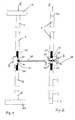
- Fig. 1 shows an embodiment of the invention with a control element in front view.
- Fig. 2 shows the same embodiment of the invention in side view.
- Fig. 3 shows the same embodiment of the invention in an oblique view.
- Fig. 4 shows a part of the housing of the actuator in side view.
- Fig. 5 shows the housing part of the housing of the actuator in front view.
- Fig. 6 shows the housing part of the housing of the actuator in an oblique view.
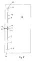
- Fig. 7 shows a door leaf with a device according to the invention, seen from the folded side.
- Fig. 8 shows a door leaf with a device according to the invention with a view of the visible surface.
- a device according to the invention for adjusting the curvature of a door leaf 4 is shown in front view.
- the device comprises an actuating part 3 and two end parts 1, 2 connected to the actuating part 3.
- the actuating part 3 comprises a shaft 31, at the ends of which in each case a thread 32, 33 is formed.
- the shaft 31 is rotatably supported with respect to the adjusting part 3 and extends along an axis X. If the device is not installed in a door leaf 4, the shaft 31 is aligned along the axis X straight.
- the shaft 31 has two external threads 32, 33 located at its two ends, which engage in internal threads 11, 21 of the two end parts 1, 2.
- the two end parts 1, 2 are elongated, for example, formed by pipes. At the end of the two end portions 1, 2 transverse extensions 13, 23 are provided which extend at right angles to the axis X.
- the external threads 32, 33 located on the shaft 31 rotate with this shaft 31. Since the two external threads 32, 33 each in internal thread 11, 12, shown in Fig. 3 , engage, increases or decreases the distance between the two end portions 1, 2 to the control part 3. It is particularly provided that at Rotation of the shaft 31, the distance between the two end portions 1, 2 increases from the control part 3 each to the same extent or decreases. In this case, advantageously, the pitch of the two threads 32, 33, and the respective associated thread 11, 12 of the end portions 1, 2 are the same size.
- the shaft 31 carry external threads 31, 32, the two end parts 1, 2 internal threads 11, 21.
- this is by no means mandatory; Alternatively, it can be provided that the shaft 31 has internal threads and the two end parts 1, 2 have corresponding external threads.
- Fig. 2 is an advantageous embodiment of the invention with a simple drive shaft 31 shown.
- the adjusting part 3 comprises a housing 36, in which parts of the shaft 31, a gear wheel 34, and a worm 35 are located.
- the gear 34 is non-rotatably or rigidly connected to the shaft 31, wherein the axis of rotation of the shaft 31 coincides with the axis of rotation of the gear 34.
- the worm 35 whose direction of rotation is advantageously normal to the axis X, cooperates with the gear 34, so that rotation of the worm 35 causes the shaft to rotate.
- control part 3 as in 4 to 6 shown, a housing 36 having a recess 301 for the shaft 31, a recess 304 for the gear 34, and a recess 305 for the screw 35.
- the respective recesses 301, 304, 305 are designed so that the shaft 31, the gear 34, and the screw 35 are not hindered in their rotational movements of the housing 36.
- Fig. 4 is a half-part of the housing 36 shown, the housing 36 of the actuating part 3, by joining two similar in Fig. 4 shown housing parts can be achieved.
- the housing part has a window-shaped actuating recess 39, through which an operating element 38 can drive the worm 35.
- the worm 35 has a coupling into which an operating element 38, for example a square or hexagonal wrench, can engage or with which the operating element 38 can interact.
- an operating element 38 for example a square or hexagonal wrench
- Fig. 8 shows the visible side of a door, in which the device according to the invention is installed.
- the two end parts 1, 2 are located in the upper or lower end region of the door leaf 4.
- the two end parts 1, 2 have transverse extensions 13, 23 which are located in the upper or lower end region of the door leaf 4.
- the adjusting part 3 is located halfway up the door leaf 4 in the middle between the two end parts 1, 2.
- the two end parts 1, 2 are completely identical.
- the device according to the invention is located in the vicinity of the folding area of the door leaf 4, wherein the setting part 3 is arranged directly above or below or laterally of the door lock.
- the door leaf 4 has in the rebate area an opening 45 for introducing an operating element 38 for actuating the worm 35.
- the opening 45 is arranged directly in front of the Betchen Inc. supra.
- any means for the interaction between the worm 35 and an operating element 38 can be arranged on the worm 35.
- the device according to the invention arranged immediately below one of the visible surfaces of the door leaf 4. This allows a shortening or extension of a linearly parallel to the axis X extending surface portion of the door panel 4, whereby a curvature of the door panel 4 on the setting of the device according to the invention can be fixed.
- the device according to the invention is arranged, in particular screwed, on the surface of the door leaf 4, in particular directly on the visible surface of the door leaf 4.
- two longitudinal recesses 41, 42 are milled, which serve to receive one of the two end portions 1, 2.
- these longitudinal recesses 41, 42 open in transverse to the axis X and the shaft 31 extending further transverse recesses 46 which receive the transverse extensions 13, 23 of the two end portions 1, 2.
- the transverse recesses 46 extend at right angles to the common axis X.
- the door leaf 4 has a recess 43 for the setting part 3 and a recess 44 for receiving or carrying the shaft 31.
- the recess 44 for receiving the implementation of the shaft 31 may be either superficially excluded in the body of the door panel 4, in particular milled out, or be provided as a cylindrical bore. In order to achieve an advantageous appearance of the door, it is possible to cover the recesses extending in the door leaf 4 after installation of the device according to the invention with a cover from the outside.
Landscapes
- Engineering & Computer Science (AREA)
- Architecture (AREA)
- Civil Engineering (AREA)
- Structural Engineering (AREA)
- Extensible Doors And Revolving Doors (AREA)
- Bay Windows, Entrances, And Structural Adjustments Related Thereto (AREA)
- Transmission Devices (AREA)
Applications Claiming Priority (1)
| Application Number | Priority Date | Filing Date | Title |
|---|---|---|---|
| AT7792010A AT509783B1 (de) | 2010-05-07 | 2010-05-07 | Vorrichtung zur einstellung der krümmung eines türblatts |
Publications (3)
| Publication Number | Publication Date |
|---|---|
| EP2385209A2 true EP2385209A2 (fr) | 2011-11-09 |
| EP2385209A3 EP2385209A3 (fr) | 2013-04-03 |
| EP2385209B1 EP2385209B1 (fr) | 2014-07-02 |
Family
ID=44453775
Family Applications (1)
| Application Number | Title | Priority Date | Filing Date |
|---|---|---|---|
| EP20110450057 Not-in-force EP2385209B1 (fr) | 2010-05-07 | 2011-05-03 | Dispositif de réglage de l'inclinaison d'un vantail |
Country Status (2)
| Country | Link |
|---|---|
| EP (1) | EP2385209B1 (fr) |
| AT (1) | AT509783B1 (fr) |
Cited By (1)
| Publication number | Priority date | Publication date | Assignee | Title |
|---|---|---|---|---|
| IT201700057159A1 (it) * | 2017-05-25 | 2018-11-25 | Otlav Spa | Tirante per raddrizzare un’anta e metodo per montare detto tirante su un'anta |
Citations (2)
| Publication number | Priority date | Publication date | Assignee | Title |
|---|---|---|---|---|
| WO1985003169A1 (fr) | 1983-12-29 | 1985-07-18 | Suntron Industrial Co., Ltd. | Antenne |
| WO2001045206A1 (fr) | 1999-12-14 | 2001-06-21 | Ems Technologies, Inc. | Antenne omnidirectionnelle utilisant un bicone asymetrique comme alimentation passive d'un element rayonnant |
Family Cites Families (9)
| Publication number | Priority date | Publication date | Assignee | Title |
|---|---|---|---|---|
| CH606747A5 (en) * | 1977-02-23 | 1978-11-15 | Monnard Grangier Jean | Adjustable metal strap correcting warp on timber doors |
| DE2819373A1 (de) * | 1978-05-03 | 1979-11-08 | Hbi Holz Bau Ind Gmbh & Co Kg | Justierbeschlag, insbesondere fuer tueren |
| CH653087A5 (en) * | 1981-05-15 | 1985-12-13 | Heinrich Hatt Haller Ag | Device for straightening warped articles, in particular entry doors |
| DE8602976U1 (de) * | 1986-02-05 | 1986-04-03 | Westag & Getalit AG, 4840 Rheda-Wiedenbrück | Plattenförmiges Bauelement, insbesondere Türblatt |
| DE8708885U1 (de) * | 1987-06-26 | 1987-08-20 | Wagner, Bodo, 8222 Ruhpolding | Verstellbare Verzugsicherung |
| CH686735A5 (de) * | 1993-04-29 | 1996-06-14 | Eku Ag | Ausrichtbeschlag fuer eine Schiebetuer. |
| DE29622285U1 (de) * | 1996-12-21 | 1997-04-17 | Höhbauer GmbH, 92706 Luhe-Wildenau | Spann- oder Richtvorrichtung sowie Türblatt bzw. Türflügel für Gebäudetüren mit einer solchen Spannvorrichtung |
| DE29720076U1 (de) * | 1997-11-12 | 1998-02-05 | Habler, Manfred, 93413 Cham | Vorrichtung zur Regulierung verzogener Haus- und Innentüren integriert im Stoßgriff/Spanngriff |
| WO2007138605A2 (fr) * | 2006-06-01 | 2007-12-06 | Hardoor Mechanism Productions Ltd. | Système et dispositif pour rigidifier une porte |
-
2010
- 2010-05-07 AT AT7792010A patent/AT509783B1/de not_active IP Right Cessation
-
2011
- 2011-05-03 EP EP20110450057 patent/EP2385209B1/fr not_active Not-in-force
Patent Citations (2)
| Publication number | Priority date | Publication date | Assignee | Title |
|---|---|---|---|---|
| WO1985003169A1 (fr) | 1983-12-29 | 1985-07-18 | Suntron Industrial Co., Ltd. | Antenne |
| WO2001045206A1 (fr) | 1999-12-14 | 2001-06-21 | Ems Technologies, Inc. | Antenne omnidirectionnelle utilisant un bicone asymetrique comme alimentation passive d'un element rayonnant |
Cited By (2)
| Publication number | Priority date | Publication date | Assignee | Title |
|---|---|---|---|---|
| IT201700057159A1 (it) * | 2017-05-25 | 2018-11-25 | Otlav Spa | Tirante per raddrizzare un’anta e metodo per montare detto tirante su un'anta |
| EP3406824A1 (fr) * | 2017-05-25 | 2018-11-28 | OTLAV SpA | Tirant et procédé de montage de celui-ci |
Also Published As
| Publication number | Publication date |
|---|---|
| EP2385209A3 (fr) | 2013-04-03 |
| EP2385209B1 (fr) | 2014-07-02 |
| AT509783B1 (de) | 2012-11-15 |
| AT509783A1 (de) | 2011-11-15 |
Similar Documents
| Publication | Publication Date | Title |
|---|---|---|
| EP2815681B1 (fr) | Mécanisme de réglage destiné à régler les parties mobiles d'un meuble | |
| AT16472U1 (de) | Stellantrieb für eine Möbelklappe | |
| EP1274908B1 (fr) | Verrou destine a etre monte dans une ouverture pratiquee dans une paroi mince | |
| WO2013020815A1 (fr) | Système de fixation pour fixer une pièce sur une rainure d'une fenêtre, d'une porte ou analogue | |
| DE102012204909A1 (de) | Tretroller mit mindestens zwei Rädern | |
| EP3103948B1 (fr) | Penture pour une porte ou une fenêtre | |
| DE60011003T2 (de) | Permanente Verankerungsvorrichtung | |
| WO2013174677A1 (fr) | Dispositif de fixation | |
| DE102015004515A1 (de) | Befestigungsvorrichtung | |
| DE10361445B4 (de) | Kraftfahrzeugtürschloss | |
| DE102012112084A1 (de) | Türschließer mit verstellbarer Federeinheit | |
| EP2385209B1 (fr) | Dispositif de réglage de l'inclinaison d'un vantail | |
| DE102007029448A1 (de) | Werkzeug | |
| EP3348773B1 (fr) | Dispositif d'ouverture, de fermeture et de verrouillage des lamelles d'une structure en lamelles | |
| DE2302286A1 (de) | Ausstellvorrichtung fuer die fluegel von fenstern, tueren od. dgl., insbesondere fuer dreh-kippfluegel | |
| DE102016102380A1 (de) | Schloss für Brandschutztür | |
| EP3162994B1 (fr) | Mécanisme d'entraînement pour une ferrure à crémone | |
| EP1614844A2 (fr) | Dispositif d'articulation | |
| EP2578891B1 (fr) | Adapteur | |
| DE102010028603B3 (de) | Beschlagteil zur Befestigung an einer C-förmigen Beschlagteilnut | |
| DE102010032145B4 (de) | Torverriegelungsvorrichtung sowie Überkopftor umfassend eine Torverriegelungsvorrichtung | |
| DE202015003728U1 (de) | Drehflügeltür mit Torsionsstab | |
| DE102009056878A1 (de) | Tür für einen Kraftwagen | |
| EP1757762B2 (fr) | Articulation à charnière, pour fenêtres, portes ou similaires | |
| DE102004030877B4 (de) | Offenstellungsarretierung für Tür- und Fensterflügel |
Legal Events
| Date | Code | Title | Description |
|---|---|---|---|
| AK | Designated contracting states |
Kind code of ref document: A2 Designated state(s): AL AT BE BG CH CY CZ DE DK EE ES FI FR GB GR HR HU IE IS IT LI LT LU LV MC MK MT NL NO PL PT RO RS SE SI SK SM TR |
|
| AX | Request for extension of the european patent |
Extension state: BA ME |
|
| PUAI | Public reference made under article 153(3) epc to a published international application that has entered the european phase |
Free format text: ORIGINAL CODE: 0009012 |
|
| PUAL | Search report despatched |
Free format text: ORIGINAL CODE: 0009013 |
|
| AK | Designated contracting states |
Kind code of ref document: A3 Designated state(s): AL AT BE BG CH CY CZ DE DK EE ES FI FR GB GR HR HU IE IS IT LI LT LU LV MC MK MT NL NO PL PT RO RS SE SI SK SM TR |
|
| AX | Request for extension of the european patent |
Extension state: BA ME |
|
| RIC1 | Information provided on ipc code assigned before grant |
Ipc: E06B 3/82 20060101ALI20130226BHEP Ipc: E06B 3/70 20060101AFI20130226BHEP |
|
| 17P | Request for examination filed |
Effective date: 20131003 |
|
| RBV | Designated contracting states (corrected) |
Designated state(s): AL AT BE BG CH CY CZ DE DK EE ES FI FR GB GR HR HU IE IS IT LI LT LU LV MC MK MT NL NO PL PT RO RS SE SI SK SM TR |
|
| GRAP | Despatch of communication of intention to grant a patent |
Free format text: ORIGINAL CODE: EPIDOSNIGR1 |
|
| INTG | Intention to grant announced |
Effective date: 20131205 |
|
| GRAS | Grant fee paid |
Free format text: ORIGINAL CODE: EPIDOSNIGR3 |
|
| GRAA | (expected) grant |
Free format text: ORIGINAL CODE: 0009210 |
|
| AK | Designated contracting states |
Kind code of ref document: B1 Designated state(s): AL AT BE BG CH CY CZ DE DK EE ES FI FR GB GR HR HU IE IS IT LI LT LU LV MC MK MT NL NO PL PT RO RS SE SI SK SM TR |
|
| REG | Reference to a national code |
Ref country code: GB Ref legal event code: FG4D Free format text: NOT ENGLISH |
|
| REG | Reference to a national code |
Ref country code: CH Ref legal event code: EP Ref country code: AT Ref legal event code: REF Ref document number: 676045 Country of ref document: AT Kind code of ref document: T Effective date: 20140715 |
|
| REG | Reference to a national code |
Ref country code: IE Ref legal event code: FG4D Free format text: LANGUAGE OF EP DOCUMENT: GERMAN |
|
| REG | Reference to a national code |
Ref country code: DE Ref legal event code: R096 Ref document number: 502011003620 Country of ref document: DE Effective date: 20140814 |
|
| REG | Reference to a national code |
Ref country code: CH Ref legal event code: NV Representative=s name: PATENTANWAELTE SCHAAD, BALASS, MENZL AND PARTN, CH |
|
| REG | Reference to a national code |
Ref country code: NL Ref legal event code: T3 |
|
| REG | Reference to a national code |
Ref country code: LT Ref legal event code: MG4D |
|
| PG25 | Lapsed in a contracting state [announced via postgrant information from national office to epo] |
Ref country code: SE Free format text: LAPSE BECAUSE OF FAILURE TO SUBMIT A TRANSLATION OF THE DESCRIPTION OR TO PAY THE FEE WITHIN THE PRESCRIBED TIME-LIMIT Effective date: 20140702 Ref country code: BG Free format text: LAPSE BECAUSE OF FAILURE TO SUBMIT A TRANSLATION OF THE DESCRIPTION OR TO PAY THE FEE WITHIN THE PRESCRIBED TIME-LIMIT Effective date: 20141002 Ref country code: GR Free format text: LAPSE BECAUSE OF FAILURE TO SUBMIT A TRANSLATION OF THE DESCRIPTION OR TO PAY THE FEE WITHIN THE PRESCRIBED TIME-LIMIT Effective date: 20141003 Ref country code: CZ Free format text: LAPSE BECAUSE OF FAILURE TO SUBMIT A TRANSLATION OF THE DESCRIPTION OR TO PAY THE FEE WITHIN THE PRESCRIBED TIME-LIMIT Effective date: 20140702 Ref country code: ES Free format text: LAPSE BECAUSE OF FAILURE TO SUBMIT A TRANSLATION OF THE DESCRIPTION OR TO PAY THE FEE WITHIN THE PRESCRIBED TIME-LIMIT Effective date: 20140702 Ref country code: FI Free format text: LAPSE BECAUSE OF FAILURE TO SUBMIT A TRANSLATION OF THE DESCRIPTION OR TO PAY THE FEE WITHIN THE PRESCRIBED TIME-LIMIT Effective date: 20140702 Ref country code: LT Free format text: LAPSE BECAUSE OF FAILURE TO SUBMIT A TRANSLATION OF THE DESCRIPTION OR TO PAY THE FEE WITHIN THE PRESCRIBED TIME-LIMIT Effective date: 20140702 Ref country code: PT Free format text: LAPSE BECAUSE OF FAILURE TO SUBMIT A TRANSLATION OF THE DESCRIPTION OR TO PAY THE FEE WITHIN THE PRESCRIBED TIME-LIMIT Effective date: 20141103 Ref country code: NO Free format text: LAPSE BECAUSE OF FAILURE TO SUBMIT A TRANSLATION OF THE DESCRIPTION OR TO PAY THE FEE WITHIN THE PRESCRIBED TIME-LIMIT Effective date: 20141002 |
|
| PG25 | Lapsed in a contracting state [announced via postgrant information from national office to epo] |
Ref country code: IS Free format text: LAPSE BECAUSE OF FAILURE TO SUBMIT A TRANSLATION OF THE DESCRIPTION OR TO PAY THE FEE WITHIN THE PRESCRIBED TIME-LIMIT Effective date: 20141102 Ref country code: HR Free format text: LAPSE BECAUSE OF FAILURE TO SUBMIT A TRANSLATION OF THE DESCRIPTION OR TO PAY THE FEE WITHIN THE PRESCRIBED TIME-LIMIT Effective date: 20140702 Ref country code: RS Free format text: LAPSE BECAUSE OF FAILURE TO SUBMIT A TRANSLATION OF THE DESCRIPTION OR TO PAY THE FEE WITHIN THE PRESCRIBED TIME-LIMIT Effective date: 20140702 Ref country code: CY Free format text: LAPSE BECAUSE OF FAILURE TO SUBMIT A TRANSLATION OF THE DESCRIPTION OR TO PAY THE FEE WITHIN THE PRESCRIBED TIME-LIMIT Effective date: 20140702 Ref country code: PL Free format text: LAPSE BECAUSE OF FAILURE TO SUBMIT A TRANSLATION OF THE DESCRIPTION OR TO PAY THE FEE WITHIN THE PRESCRIBED TIME-LIMIT Effective date: 20140702 Ref country code: LV Free format text: LAPSE BECAUSE OF FAILURE TO SUBMIT A TRANSLATION OF THE DESCRIPTION OR TO PAY THE FEE WITHIN THE PRESCRIBED TIME-LIMIT Effective date: 20140702 |
|
| REG | Reference to a national code |
Ref country code: DE Ref legal event code: R097 Ref document number: 502011003620 Country of ref document: DE |
|
| PG25 | Lapsed in a contracting state [announced via postgrant information from national office to epo] |
Ref country code: DK Free format text: LAPSE BECAUSE OF FAILURE TO SUBMIT A TRANSLATION OF THE DESCRIPTION OR TO PAY THE FEE WITHIN THE PRESCRIBED TIME-LIMIT Effective date: 20140702 Ref country code: SK Free format text: LAPSE BECAUSE OF FAILURE TO SUBMIT A TRANSLATION OF THE DESCRIPTION OR TO PAY THE FEE WITHIN THE PRESCRIBED TIME-LIMIT Effective date: 20140702 Ref country code: EE Free format text: LAPSE BECAUSE OF FAILURE TO SUBMIT A TRANSLATION OF THE DESCRIPTION OR TO PAY THE FEE WITHIN THE PRESCRIBED TIME-LIMIT Effective date: 20140702 Ref country code: RO Free format text: LAPSE BECAUSE OF FAILURE TO SUBMIT A TRANSLATION OF THE DESCRIPTION OR TO PAY THE FEE WITHIN THE PRESCRIBED TIME-LIMIT Effective date: 20140702 |
|
| PLBE | No opposition filed within time limit |
Free format text: ORIGINAL CODE: 0009261 |
|
| STAA | Information on the status of an ep patent application or granted ep patent |
Free format text: STATUS: NO OPPOSITION FILED WITHIN TIME LIMIT |
|
| 26N | No opposition filed |
Effective date: 20150407 |
|
| PG25 | Lapsed in a contracting state [announced via postgrant information from national office to epo] |
Ref country code: SI Free format text: LAPSE BECAUSE OF FAILURE TO SUBMIT A TRANSLATION OF THE DESCRIPTION OR TO PAY THE FEE WITHIN THE PRESCRIBED TIME-LIMIT Effective date: 20140702 |
|
| GBPC | Gb: european patent ceased through non-payment of renewal fee |
Effective date: 20150503 |
|
| PG25 | Lapsed in a contracting state [announced via postgrant information from national office to epo] |
Ref country code: MC Free format text: LAPSE BECAUSE OF FAILURE TO SUBMIT A TRANSLATION OF THE DESCRIPTION OR TO PAY THE FEE WITHIN THE PRESCRIBED TIME-LIMIT Effective date: 20140702 Ref country code: IT Free format text: LAPSE BECAUSE OF NON-PAYMENT OF DUE FEES Effective date: 20150503 |
|
| REG | Reference to a national code |
Ref country code: NL Ref legal event code: MM Effective date: 20150601 |
|
| REG | Reference to a national code |
Ref country code: IE Ref legal event code: MM4A |
|
| REG | Reference to a national code |
Ref country code: FR Ref legal event code: ST Effective date: 20160129 |
|
| PG25 | Lapsed in a contracting state [announced via postgrant information from national office to epo] |
Ref country code: GB Free format text: LAPSE BECAUSE OF NON-PAYMENT OF DUE FEES Effective date: 20150503 Ref country code: NL Free format text: LAPSE BECAUSE OF NON-PAYMENT OF DUE FEES Effective date: 20150601 Ref country code: IE Free format text: LAPSE BECAUSE OF NON-PAYMENT OF DUE FEES Effective date: 20150503 |
|
| PG25 | Lapsed in a contracting state [announced via postgrant information from national office to epo] |
Ref country code: FR Free format text: LAPSE BECAUSE OF NON-PAYMENT OF DUE FEES Effective date: 20150601 |
|
| PG25 | Lapsed in a contracting state [announced via postgrant information from national office to epo] |
Ref country code: MT Free format text: LAPSE BECAUSE OF FAILURE TO SUBMIT A TRANSLATION OF THE DESCRIPTION OR TO PAY THE FEE WITHIN THE PRESCRIBED TIME-LIMIT Effective date: 20140702 |
|
| PG25 | Lapsed in a contracting state [announced via postgrant information from national office to epo] |
Ref country code: SM Free format text: LAPSE BECAUSE OF FAILURE TO SUBMIT A TRANSLATION OF THE DESCRIPTION OR TO PAY THE FEE WITHIN THE PRESCRIBED TIME-LIMIT Effective date: 20140702 Ref country code: HU Free format text: LAPSE BECAUSE OF FAILURE TO SUBMIT A TRANSLATION OF THE DESCRIPTION OR TO PAY THE FEE WITHIN THE PRESCRIBED TIME-LIMIT; INVALID AB INITIO Effective date: 20110503 |
|
| REG | Reference to a national code |
Ref country code: AT Ref legal event code: MM01 Ref document number: 676045 Country of ref document: AT Kind code of ref document: T Effective date: 20160503 |
|
| PG25 | Lapsed in a contracting state [announced via postgrant information from national office to epo] |
Ref country code: BE Free format text: LAPSE BECAUSE OF NON-PAYMENT OF DUE FEES Effective date: 20150531 Ref country code: AT Free format text: LAPSE BECAUSE OF FAILURE TO SUBMIT A TRANSLATION OF THE DESCRIPTION OR TO PAY THE FEE WITHIN THE PRESCRIBED TIME-LIMIT Effective date: 20140702 |
|
| PG25 | Lapsed in a contracting state [announced via postgrant information from national office to epo] |
Ref country code: AT Free format text: LAPSE BECAUSE OF FAILURE TO SUBMIT A TRANSLATION OF THE DESCRIPTION OR TO PAY THE FEE WITHIN THE PRESCRIBED TIME-LIMIT Effective date: 20160503 Ref country code: TR Free format text: LAPSE BECAUSE OF FAILURE TO SUBMIT A TRANSLATION OF THE DESCRIPTION OR TO PAY THE FEE WITHIN THE PRESCRIBED TIME-LIMIT Effective date: 20140702 |
|
| PG25 | Lapsed in a contracting state [announced via postgrant information from national office to epo] |
Ref country code: MK Free format text: LAPSE BECAUSE OF FAILURE TO SUBMIT A TRANSLATION OF THE DESCRIPTION OR TO PAY THE FEE WITHIN THE PRESCRIBED TIME-LIMIT Effective date: 20140702 |
|
| PGFP | Annual fee paid to national office [announced via postgrant information from national office to epo] |
Ref country code: CH Payment date: 20180507 Year of fee payment: 8 |
|
| PG25 | Lapsed in a contracting state [announced via postgrant information from national office to epo] |
Ref country code: AL Free format text: LAPSE BECAUSE OF FAILURE TO SUBMIT A TRANSLATION OF THE DESCRIPTION OR TO PAY THE FEE WITHIN THE PRESCRIBED TIME-LIMIT Effective date: 20140702 |
|
| REG | Reference to a national code |
Ref country code: CH Ref legal event code: PL |
|
| PG25 | Lapsed in a contracting state [announced via postgrant information from national office to epo] |
Ref country code: LI Free format text: LAPSE BECAUSE OF NON-PAYMENT OF DUE FEES Effective date: 20190531 Ref country code: CH Free format text: LAPSE BECAUSE OF NON-PAYMENT OF DUE FEES Effective date: 20190531 |
|
| P01 | Opt-out of the competence of the unified patent court (upc) registered |
Effective date: 20230510 |
|
| PGFP | Annual fee paid to national office [announced via postgrant information from national office to epo] |
Ref country code: LU Payment date: 20230515 Year of fee payment: 13 |
|
| PGFP | Annual fee paid to national office [announced via postgrant information from national office to epo] |
Ref country code: DE Payment date: 20230526 Year of fee payment: 13 |
|
| REG | Reference to a national code |
Ref country code: DE Ref legal event code: R119 Ref document number: 502011003620 Country of ref document: DE |
|
| PG25 | Lapsed in a contracting state [announced via postgrant information from national office to epo] |
Ref country code: LU Free format text: LAPSE BECAUSE OF NON-PAYMENT OF DUE FEES Effective date: 20240503 |
|
| PG25 | Lapsed in a contracting state [announced via postgrant information from national office to epo] |
Ref country code: LU Free format text: LAPSE BECAUSE OF NON-PAYMENT OF DUE FEES Effective date: 20240503 |
|
| PG25 | Lapsed in a contracting state [announced via postgrant information from national office to epo] |
Ref country code: DE Free format text: LAPSE BECAUSE OF NON-PAYMENT OF DUE FEES Effective date: 20241203 |