EP3348773B1 - Dispositif d'ouverture, de fermeture et de verrouillage des lamelles d'une structure en lamelles - Google Patents
Dispositif d'ouverture, de fermeture et de verrouillage des lamelles d'une structure en lamelles Download PDFInfo
- Publication number
- EP3348773B1 EP3348773B1 EP18150532.2A EP18150532A EP3348773B1 EP 3348773 B1 EP3348773 B1 EP 3348773B1 EP 18150532 A EP18150532 A EP 18150532A EP 3348773 B1 EP3348773 B1 EP 3348773B1
- Authority
- EP
- European Patent Office
- Prior art keywords
- lamella
- coupling rod
- driver pin
- frame profile
- arm
- Prior art date
- Legal status (The legal status is an assumption and is not a legal conclusion. Google has not performed a legal analysis and makes no representation as to the accuracy of the status listed.)
- Active
Links
Images




Classifications
-
- E—FIXED CONSTRUCTIONS
- E06—DOORS, WINDOWS, SHUTTERS, OR ROLLER BLINDS IN GENERAL; LADDERS
- E06B—FIXED OR MOVABLE CLOSURES FOR OPENINGS IN BUILDINGS, VEHICLES, FENCES OR LIKE ENCLOSURES IN GENERAL, e.g. DOORS, WINDOWS, BLINDS, GATES
- E06B7/00—Special arrangements or measures in connection with doors or windows
- E06B7/02—Special arrangements or measures in connection with doors or windows for providing ventilation, e.g. through double windows; Arrangement of ventilation roses
- E06B7/08—Louvre doors, windows or grilles
- E06B7/084—Louvre doors, windows or grilles with rotatable lamellae
- E06B7/086—Louvre doors, windows or grilles with rotatable lamellae interconnected for concurrent movement
Definitions
- the invention relates to an arrangement for moving and locking slats of a slat construction, which are used in particular in building installations.
- Slat constructions generally have a plurality of rotatably or pivotably mounted slats which can be moved back and forth between a closed and an open state by means of a movement mechanism ( US 2,819,065 A . US 3,430,383 A. ).
- a movement mechanism US 2,819,065 A . US 3,430,383 A.
- With a suitable locking mechanism it is also possible to protect the slat construction from the direct effects of wind loads or to effectively prevent forced opening from the outside.
- the JP H08-86 162 A A violent opening is tested in accordance with DIN EN 1627 from September 2011.
- burglar-resistant windows are components which, in addition to the usual functional tasks, offer a defined resistance to break-in attempts.
- Most slat constructions hardly achieve the RC2 classification. In order to successfully survive an RC3 classification, a great deal of effort has to be expended.
- the movement mechanism is advantageously arranged within the lamella construction. To do this, it is necessary to keep this entire arrangement for moving and locking slats as compact as possible.
- the arrangement for moving consists of several lever arms on both sides of the slats.
- the lever arms are connected to the slat via two swivel joints and to the frame via two swivel joints.
- a further swivel joint connects the arrangement for movement with a linearly movable drive element and two of the lever arms.
- the lengths of the lever arms and the positions of the swivel joints make the slats tilt and open when opening and closing executed.
- one of the lever arms has a hook-shaped end which engages around a bolt fastened to the slat when the slat construction is closed.
- the shafts within the slat construction are rotatably mounted in pivot bearings.
- the end of one of the shafts is connected on one side of the lamellae with two coupling rods that can move in anti-parallel.
- the coupling rods are movably received on two pins oriented axially parallel to the axis of rotation, which are fastened to the respective shaft on both sides of the axis of rotation.
- a plate with an elongated perforation is fastened to one of the coupling rods between the pivot bearings of two adjacent slats.
- an actuating lever that can be pivoted about a pivot point is received with a handle at approximately the same position.
- the actuating lever On the side of the fulcrum opposite the handle, the actuating lever has a driver which engages in the slot-shaped opening in the plate.
- the driver is a roller rotatably mounted on a pin.
- the otherwise linear slot-shaped opening has an angled end.
- the driver of the actuating lever is located there.
- the driver To lock the angled end and the driver is positioned to the fulcrum of the operating lever that the Before reaching the angled end, the driver must exceed a reversal point, behind which the actuating lever is held in the locked position by a force emanating from the slats.
- the reversal point is where the driver crosses an imaginary connecting line to the fulcrum of the actuating lever that is oriented perpendicular to the movement vector of the coupling rods.
- the force emanating from the slats is obviously achieved here by the counterpressure of the elastic sealing elements to which the slats are applied in the closed state.
- the reversal point can only be overcome by the swiveling movement of the operating lever, which means that the slat construction cannot be opened from the outside. Locking would also work with a linear breakthrough without the angled end. With the angled end, however, the travel of the actuating lever required to assume the locked position can be shortened.
- the disadvantage is that after the reversal point is exceeded, the force acting on the sealing elements in the closed state decreases again, which can have a disadvantageous effect on the sealing of the lamella construction.
- the invention has for its object to provide a possibility for an arrangement for moving and locking a lamella construction, which is low in maintenance and consists of as few, simply constructed individual parts.
- Another object of the invention is to achieve an RC3 classification according to DIN EN 1627 from September 2011.
- the object is achieved by an arrangement for opening, closing and locking slats of a slat construction containing at least one circumferentially framed slat, a circumferential window frame profile, an opening unit, at least one coupling rod, at least one driving pin holder, at least one lever arm, at least one cam plate and at least one latch ,
- Each slat is connected laterally to the frame profile via a pivot bearing with an axis of rotation.
- At least one rotary bearing of each lamella has a shaft which has a first end face facing the lamella, which is provided with a connecting piece for receiving the lamella, and a second end face.
- the respective other pivot bearing of a lamella is a drive-less pivot bearing if there is only one coupling rod. If a coupling rod is provided on both sides of the lamella, the arrangement is constructed mirror-symmetrically.
- the opening unit consists of a linear drive, either one or two tie rods and one or two corner drives, the linear drive can be arranged at the bottom or top of the horizontally extending part of the frame profile. If there are two tie rods, the force is applied to both tie rods at the same time, which then always move in opposite directions.
- a motor lever is mounted on each tie rod. The horizontal movements of the tie rods are redirected in the corners of the frame via corner deflection into vertical movements of the coupling rods arranged vertically on the side.
- a driver pin holder with a driver pin and a lever arm are assigned to each non-drive-free rotary bearing.
- the lever arm is rotatably connected to the second end face of the shaft with a fixed end.
- In the lever arm there is an angled elongated hole, which can be subdivided into a first leg oriented radially to the axis of rotation, an apex and a second leg at a first angle ⁇ , the driving pin holder being firmly connected to the coupling rod and the driving pin protruding into the elongated hole.
- the linear movement of the coupling rod between the upper and lower end position on the driver pin holder, driver pin, lever arm and pivot bearing in a rotary movement of the slat between a closed position and changed to an open position.
- the second leg is aligned parallel to the coupling rod, as long as the driver pin is guided in the second leg between the upper end position and the apex.
- This also means that the driver pin does not initiate any rotational movement on the lamella over the path length between the upper end position and the apex.
- This idling is used to provide locking of at least one slat either on one side or on both sides.
- Each lock is constructed identically in that a cam plate is firmly connected to the coupling rod in a free area. This is preferably done to the left and / or right above or below the driven swivel joint of the corresponding lamella.
- a groove has been worked into each cam plate, which is divided into two areas, a first area parallel to the coupling rod and the subsequent second area running at a second angle ⁇ in the direction of the lamella.
- a pawl is assigned to each cam plate, the pawl being arranged non-rotatably on the frame profile.
- the pawl also has a guide pin which is arranged projecting into the groove of the cam plate.
- the pawl protrudes into a recess made in the frame and the adjoining lamella in the event that the coupling rod has assumed the upper end position.
- the guide pin In this end position of the coupling rod, the guide pin is at the end of the second area of the groove and all the driver pins are in the end area of the second leg.
- the slats have taken the closed position.
- the guide pin In the event that the coupling rod is now moved from the upper end position to the lower end position, the guide pin is moved away from the lamella by the second area of the groove at an angle, so that the pawl is thus guided out of the recess.
- the pawl is completely led out of the lamella when the guide pin has left the second area of the groove and has been transferred into the first area of the groove.
- the driver pin is still in the second leg or just at the apex of the elongated hole.
- the main advantage of the arrangement according to the invention is that firstly the slats are locked in all positions by the self-locking of the electromechanical drive, secondly when the slats are in a vertical position (closed position) there is an additional self-locking between the driving pin holder and lever arm and thirdly swivels out of the frame the latch into the closed slat and locks it so that it cannot be opened from the outside without being destroyed.
- An arrangement according to the invention allows an RC3 classification. Advantageous refinements result from the dependent claims.
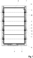
- a slat construction according to the invention are a frame profile 1, slats 2 arranged therein, which are rotatably connected to the frame profile 1 by two pivot bearings 3, a linear drive 4, which has tie rods 5 and corner deflections 6 arranged horizontally on both sides, the coupling rods 7 arranged on the left and right sides can move linearly between an upper end position O and a lower end position U, driver pin holder 8, lever arms 9, a cam plate 10 and a pawl 11.
- the pivot bearing 3 with its axis of rotation 12 has the shape of a cylindrical sleeve which is fixedly connected to the frame profile 1.
- a shaft 13 is received, which is rotatably supported about the axis of rotation 12.
- the shaft 13 has a first end face 14 and a second end face 15.
- the first end face 14, according to Fig. 3 is facing a lamella 2, on which a connector 16 is rotatably arranged.
- the connecting piece 16 is a cuboid body, with which a positive and non-positive connection to the lamella 2 can be established.
- the second end face 15 of the shaft 13 has a coaxially arranged profile extension 17 for establishing a positive and non-positive connection to the lever arm 9.
- the lever arm 9 consists of a strip-shaped flat material with a fixed end 18 and a loose end 19. With the fixed end 18, the lever arm 9 lies flat against the second end face 15 and is non-rotatably connected to the shaft 13 via a positive connection to the profile extension 17 connected.
- the lever arm 9 has an angled elongated hole 20 with a constant width b.
- the elongated hole 20 can first be divided into a first leg 21 and a straight second leg 22, the vertex S being between them.
- the included first angle ⁇ is 135 °.
- the according Fig. 2 The angled extension 23 shown is optional, but definitely advantageous, which is explained in more detail below.
- the first leg 21 pointing from the apex S to the fixed end 18 is arranged in the radial direction to the axis of rotation 12.
- a cylindrical driver pin 24 is arranged axially parallel to the axis of rotation 12. It has a slightly smaller diameter than the width b of the elongated hole 20, so that it can be moved with little play.
- the driver pin 24 is fixedly connected to a driver pin holder 8.
- the driver pin holder 8 is a body that is adjustably attached to a coupling rod 7.
- the coupling rod 7 is arranged with its axis along the frame profile 1, orthogonal to the axis of rotation 12 and with an axial distance from the axis of rotation 12.
- the Coupling rod 7 has a circular cross section and is linearly movable in two sliding bearings 25 along its axis.
- the slide bearings 25 are arranged along the coupling rod 7, symmetrically on both sides of the pivot bearing 3 and are firmly connected to the frame profile 1.
- the driving pin holder 8, which carries the driving pin 24, is received on the coupling rod 7 between the sliding bearings 25.
- the driver pin holder 8 has a through hole with which it is pushed onto the coupling rod 7.
- the attachment of the driver pin holder 8 to the coupling rod 7 is detachable and is carried out by means of threaded pins 26 screwed in radially to the coupling rod 7.
- the coupling rod 7 is connected to the linear drive 4 via corner deflection 6 and pull rod 5.
- Suitable linear drives 4 are known from the prior art and are not described further here. With the linear drive 4, the coupling rod 7 is linearly displaced in the slide bearings 25.
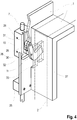
- Fig. 4 and Fig. 5 show an enlarged section of the locking mechanism.
- a curve plate 10 is attached on the upper end of the coupling rod 7, as already in Fig. 1 indicated.
- the cam plate 10 is also fastened to the coupling rod 7 like the driver pin holder 8, the fastening being releasable and done by means of threaded pins 26 screwed in radially to the coupling rod 7.
- a groove 28 has been worked into the cam plate 10 and is divided into two areas, a first area 29 parallel to the coupling rod 7 and the adjoining second area 30 at a second angle ⁇ ( Fig. 5 ) runs in the direction of lamella 2.
- the pawl 11 is assigned to the cam plate 10, the pawl 11 being arranged on the window frame profile 1 in a rotationally fixed manner by means of a connection 31.
- the pawl 11 also has a guide pin 32 which is arranged projecting into the groove 28 of the cam plate 10.
- the pawl 11 protrudes accordingly Fig. 4 through an opening 33 made in the frame profile 1 into a recess 27 made in the adjacent framed lamella 2.
- Fig. 2 and Fig. 4 show the state of the closed and locked slat 2 by the coupling rod 7 is in the upper end position O. According to Fig. 2 It is clear that the coupling rod 7 has a slight path over the upper end position O can be performed. As a result, the driver pin 24 is guided into the angled extension 23, as a result of which the lamella 2 is pressed and firmly closed.
- the axial distance between the axis of rotation 12 and the coupling rod 7 and thus also the lever arm 9 is kept as short as possible.
- the lever arm 9 takes up an angle of approximately 45 ° to the imaginary horizontal H.
- the first angle ⁇ and a radius r of the vertex S to the axis of rotation 12 are coordinated.
- other values for the radius r and the first angle ⁇ are also possible, with only a first angle ⁇ in the size range being given the aforementioned specifications and usual opening angles of slats 2 of a slat construction between 120 ° and 150 ° makes sense.
- the values for the first angle ⁇ are always to be selected such that the second leg 22 runs parallel to the coupling rod 7 in the closed state.
- the lamella 2 is already locked against opening from the outside, since the coupling rod 7 is decoupled from forces (torques about the axis of rotation 12).
- the decoupling of the coupling rod 7 is achieved because the driver pin holder 8 for driving the lamella 2 is positively connected to the frame profile 1, but can execute the direction of movement of the coupling rod 7.
- the force is transmitted from the shaft 13 via the lever arm 9 to the driver pin 24.
- a moment acting on the driver pin 24 is oriented almost orthogonally to the course of the coupling rod 7 due to the orientation of the second leg 22.
- the force introduced is transmitted radially to the slide bearing 25 via the driving pin holder 8 and the coupling rod 7 and is diverted into the frame profile 1.
- a portion of the force acting on the coupling rod 7 in the axial direction is, if any, vanishingly low, so that any force acting on the lamella 2 from the outside cannot be converted into a directed force in the direction of movement of the coupling rod 7. Therefore, the linear drive 4 connected to the coupling rod 7 does not require high holding forces and can accordingly be designed to be small and cost-saving. It also blocks how out Fig. 4 can be seen, the pawl 11 opening.
- the coupling rod 7 is moved downward from the upper end position O by the linear drive 4.
- the driver pin 24 within the second leg 22 of the elongated hole 20 and the guide pin 32 in the second region 30 of the groove 28 are simultaneously shifted downward by the path length c, which in this embodiment has a value of 12 mm. Since the second leg 22 runs parallel to the coupling rod 7, the displacement of the driver pin 24 within the second leg 22 initially does not cause any movement of the lever arm 9 and thus also no movement of the lamella 2.
- the driver pin 24 dips into the elongated hole 20 in the first leg 21 and presses the lever arm 9 in the direction of the lower end position U, see Fig. 6c , whereby the shaft 13 is rotated about the axis of rotation 12 and thus the lamella 2 opens.
- the controlled movement of the lamella 2 can be continued up to a lower end position U of the coupling rod 7.
- the slat 2 In the lower end position U, the slat 2 is in the fully open state.
- the positions of the upper end position O and lower end position U depend on the desired positions of the lamella 2 in the open and closed state and are determined by the configuration of the linear drive 4.
- the driver pin 24 passes the imaginary horizontal H to reach the lower end position U.
- the driver pin 24 approaches tangentially to the axis of rotation 12.
- a distance a existing between the axis of rotation 12 and the end of the first leg 21 is therefore always chosen such that the first leg 21 does not limit the tangential approach.
- each lamella 2 with only one lever arm 9, one driver pin holder 8 and driver pin 24 is connected to the coupling rod 7.
- a plurality of slide bearings 25 are provided for the linearly movable mounting of the coupling rod 7.
- the number of slide bearings 25 corresponds at least to the number of plates 2, the slide bearings 25 being arranged symmetrically between the pivot bearings 3 of the plates 2. All slats 2 of the slat construction are moved together by the driven coupling rod 7.
- a further embodiment for a lamella construction with a plurality of lamellae 2 is that each lamella 2 on each side with an arrangement for moving and locking according to the Figures 6a to 6c is provided.
- the two coupling rods 7 are then deflected in the lower or upper area of the lamella construction and moved via the only horizontally arranged linear drive 4.
- each lamella 2 can be equipped with two pawls 11 so that it can be locked.
Landscapes
- Engineering & Computer Science (AREA)
- Civil Engineering (AREA)
- Structural Engineering (AREA)
- Specific Sealing Or Ventilating Devices For Doors And Windows (AREA)
- Blinds (AREA)
- Underground Structures, Protecting, Testing And Restoring Foundations (AREA)
Claims (10)
- Dispositif d'ouverture, de fermeture et de verrouillage de lamelles (2) d'une construction lamellaire comprenant
au moins une lamelle (2) encadrée circonférentiellement, un profil faux cadre (1) circonférentiel, une unité d'ouverture, au moins une tige d'accouplement (7), au moins un support de tenon d'entraînement (8), au moins un bras de levier (9), au moins une plaque à came (10) et au moins un cliquet (11), où- l'au moins une lamelle (2) encadrée circonférentiellement est disposée en liaison latérale avec le profil faux cadre (1) par l'intermédiaire d'un palier rotatif (3) avec un axe de rotation (12), où- au moins l'un des paliers rotatifs (3) présente un arbre (13) avec une première face d'extrémité (14) tournée vers la lamelle (2) et munie d'une pièce de liaison (16) pour recevoir la lamelle (2), et une deuxième face d'extrémité (15),- l'unité d'ouverture comprend un entraînement linéaire (4), au moins une tige de traction (5) et au moins un renvoi d'angle (6), l'entraînement linéaire (4) étant disposé en bas ou en haut de la partie s'étendant horizontalement du profil faux cadre (1) et une force étant introduite sur l'au moins une tige de traction (5) et chaque tige de traction (5) étant reliée, par un renvoi d'angle (6), au moins une tige d'accouplement (7) disposée verticalement dans le profil faux cadre (1), en direction latérale,- un support de tenon d'entraînement (8) avec un tenon d'entraînement (24) et un bras de levier (9) est associé à chaque arbre (13), où- le bras de levier (9) a une extrémité fixe (18) disposée de manière fixe en rotation sur la deuxième face d'extrémité (15) de l'arbre (13) et présente un trou oblong incliné (20) qui peut être subdivisé en un premier bras (21) orienté radialement par rapport à l'axe de rotation (12), un sommet (S) et un deuxième bras (22) disposé sous un premier angle (α),- le support de tenon d'entraînement (8) présente une liaison fixe avec la tige d'accouplement (7) et le tenon d'entraînement (24) est disposé en saillie dans la fente (20), de sorte que le mouvement linéaire de la tige d'accouplement (7) entre une position d'extrémité supérieure (O) et une position d'extrémité inférieure (U) peut être converti en un mouvement de rotation de la lamelle (2) entre une position fermée et une position ouverte par le support de tenon d'entraînement (8), le tenon d'entraînement (24), le bras de levier (9) et l'arbre (13), et- le deuxième bras (22) est aligné parallèlement à la tige d'accouplement (7) lorsque le tenon d'entraînement (24) est guidé dans le deuxième bras (22) entre la position d'extrémité supérieure (O) et le sommet (S),- chaque plaque de came (10) présente une liaison fixe avec l'une des tiges d'accouplement (7) et dans chaque plaque de came (10) se trouve une rainure (28) divisée en deux zones, une première zone (29) étant disposée parallèlement à la tige d'accouplement (7) et la deuxième zone adjacente (30) étant disposée selon un deuxième angle (β) dans la direction des lamelles (2), où- un cliquet (11) est associé à chaque plaque de came (10), où- le cliquet (11) est disposé de manière non rotative sur le profil faux cadre (1),- le cliquet (11) comporte un pivot de guidage (32) qui est disposé en saillie dans la rainure (28) de la plaque à came (10), et- un trou (33) est prévu dans le profil faux cadre (1), et dans la lamelle encadrée adjacente (2) il y a un évidement (27)- dans lequel le cliquet (11) fait saillie lorsque la position d'extrémité supérieure (O) est réglée, le pivot de guidage (32) étant disposée simultanément à l'extrémité de la deuxième région (30) de la rainure (28) et tous les tenons d'entraînement (24) étant disposés dans la région finale des deuxièmes bras (22) et les lamelles (2) ayant pris la position fermée, ou- à partir duquel le cliquet (11) fait saillie lorsque le pivot de guidage (32) se trouve dans la première région (29) de la rainure (28),- le pivot de guidage (32) se trouve dans la deuxième région (30) de la rainure (28) uniquement si le tenon d'entraînement (24) se trouve dans le deuxième bras (22) et la lamelle (2) est en position fermée. - Dispositif selon la revendication 1, caractérisé en ce qu'un insert en forme de boîte est disposé dans l'évidement (27) de la lamelle encadrée (2).
- Dispositif selon la revendication 1 ou 2, caractérisé en ce que le premier angle (α) a une valeur de 135°.
- Dispositif selon les revendications 1 à 3, caractérisé en ce que le deuxième angle (β) a une valeur dans la plage supérieure à 90° et inférieure à 180°, de préférence une valeur de 135°.
- Dispositif selon les revendications 1 à 4, caractérisé en ce qu'un rayon (r) entre le sommet (S) et l'axe de rotation (12) est supérieur à une distance minimale (a) entre le tenon d'entraînement (24) et l'axe de rotation (12).
- Dispositif selon les revendications 1 à 5, caractérisé en ce que le support de tenon d'entraînement (8) est disposé dans le profil faux cadre (1) de manière à assurer un verrouillage positif.
- Dispositif selon les revendications 1 à 6, caractérisé en ce que des paliers lisses (25) pour le guidage linéaire de la tige d'accouplement (7) sont disposés symétriquement par rapport aux paliers rotatifs (3).
- Dispositif selon les revendications 1 à 7, caractérisé en ce que dans une construction lamellaire à plusieurs lamelles (2), chaque lamelle (2) est disposée pour être reliée à une tige d'accouplement (7) par un bras de levier (9) et un tenon d'entraînement (24) sur les côtés gauche et droit.
- Dispositif selon les revendications 1 à 8, caractérisé en ce que, pour des raisons de stabilité, deux tiges d'accouplement (7) reliées l'une à l'autre et pouvant être déplacées simultanément entre leurs positions d'extrémité (O et U) par l'un entraînement linéaire (4) sont disposées des deux côtés du profil faux cadre (1).
- Dispositif selon les revendications 1 à 9, caractérisé en ce que le deuxième bras (22) du trou oblong (20) présente une extension inclinée (23) du trou oblong (20) dans la zone d'extrémité, grâce à laquelle une force de pression peut être produite sur la lamelle (2) après avoir pris la position fermée.
Priority Applications (3)
| Application Number | Priority Date | Filing Date | Title |
|---|---|---|---|
| PL18150532T PL3348773T3 (pl) | 2017-01-13 | 2018-01-08 | Układ do otwierania, zamykania i ryglowania lameli konstrukcji lamelowej |
| SI201830039T SI3348773T1 (sl) | 2017-01-13 | 2018-01-08 | Razporeditev za odpiranje, zapiranje in zapahnitev lamel lamelne konstrukcije |
| HRP20200374TT HRP20200374T1 (hr) | 2017-01-13 | 2020-03-06 | Uređaj za otvaranje, zatvaranje i blokiranje lamela lamelarne konstrukcije |
Applications Claiming Priority (1)
| Application Number | Priority Date | Filing Date | Title |
|---|---|---|---|
| DE102017100658.3A DE102017100658B4 (de) | 2017-01-13 | 2017-01-13 | Anordnung zum Öffnen, Schließen und Verriegeln von Lamellen einer Lamellenkonstruktion |
Publications (2)
| Publication Number | Publication Date |
|---|---|
| EP3348773A1 EP3348773A1 (fr) | 2018-07-18 |
| EP3348773B1 true EP3348773B1 (fr) | 2019-12-18 |
Family
ID=60942906
Family Applications (1)
| Application Number | Title | Priority Date | Filing Date |
|---|---|---|---|
| EP18150532.2A Active EP3348773B1 (fr) | 2017-01-13 | 2018-01-08 | Dispositif d'ouverture, de fermeture et de verrouillage des lamelles d'une structure en lamelles |
Country Status (10)
| Country | Link |
|---|---|
| EP (1) | EP3348773B1 (fr) |
| AU (1) | AU2018200261A1 (fr) |
| DE (1) | DE102017100658B4 (fr) |
| DK (1) | DK3348773T3 (fr) |
| ES (1) | ES2774550T3 (fr) |
| HR (1) | HRP20200374T1 (fr) |
| HU (1) | HUE049143T2 (fr) |
| PL (1) | PL3348773T3 (fr) |
| PT (1) | PT3348773T (fr) |
| SI (1) | SI3348773T1 (fr) |
Families Citing this family (2)
| Publication number | Priority date | Publication date | Assignee | Title |
|---|---|---|---|---|
| CN109168776B (zh) * | 2018-09-12 | 2020-10-27 | 常州大学 | 一种防倾倒防移动的植物生长实验架装置 |
| DE102023108434A1 (de) * | 2023-04-03 | 2024-10-10 | Lamilux Heinrich Strunz Gmbh | Lamellenfenster |
Family Cites Families (6)
| Publication number | Priority date | Publication date | Assignee | Title |
|---|---|---|---|---|
| US2819065A (en) | 1954-05-25 | 1958-01-07 | Gate City Sash And Door Compan | Awning window structure |
| US3430383A (en) | 1967-06-08 | 1969-03-04 | Al Brenner | Awning window |
| GB1396285A (en) | 1971-06-25 | 1975-06-04 | Pillar Naco Uk Ltd | Louvre windows |
| JP2920350B2 (ja) | 1994-09-16 | 1999-07-19 | 中西金属工業株式会社 | 回転窓 |
| CN2589642Y (zh) * | 2002-12-31 | 2003-12-03 | 林烈章 | 透明转叶防护窗 |
| DE102009005594B4 (de) | 2009-01-21 | 2011-05-19 | Mp2 Gmbh | Lamellenfenster |
-
2017
- 2017-01-13 DE DE102017100658.3A patent/DE102017100658B4/de not_active Expired - Fee Related
-
2018
- 2018-01-08 EP EP18150532.2A patent/EP3348773B1/fr active Active
- 2018-01-08 ES ES18150532T patent/ES2774550T3/es active Active
- 2018-01-08 SI SI201830039T patent/SI3348773T1/sl unknown
- 2018-01-08 PT PT181505322T patent/PT3348773T/pt unknown
- 2018-01-08 DK DK18150532.2T patent/DK3348773T3/da active
- 2018-01-08 HU HUE18150532A patent/HUE049143T2/hu unknown
- 2018-01-08 PL PL18150532T patent/PL3348773T3/pl unknown
- 2018-01-12 AU AU2018200261A patent/AU2018200261A1/en not_active Abandoned
-
2020
- 2020-03-06 HR HRP20200374TT patent/HRP20200374T1/hr unknown
Non-Patent Citations (1)
| Title |
|---|
| None * |
Also Published As
| Publication number | Publication date |
|---|---|
| EP3348773A1 (fr) | 2018-07-18 |
| SI3348773T1 (sl) | 2020-04-30 |
| DE102017100658A1 (de) | 2018-07-19 |
| PT3348773T (pt) | 2020-03-16 |
| ES2774550T3 (es) | 2020-07-21 |
| HUE049143T2 (hu) | 2020-08-28 |
| HRP20200374T1 (hr) | 2020-06-12 |
| DK3348773T3 (da) | 2020-03-23 |
| DE102017100658B4 (de) | 2019-03-28 |
| PL3348773T3 (pl) | 2020-08-24 |
| AU2018200261A1 (en) | 2018-08-02 |
Similar Documents
| Publication | Publication Date | Title |
|---|---|---|
| EP3271538B1 (fr) | Charnière pour porte ou fenêtre | |
| WO1991017334A1 (fr) | Fermeture a levier pivotant verrouillee par une serrure a pompe | |
| AT16936U1 (de) | Vorrichtung zum Bewegen einer Schiebetür oder Falt-Schiebetür | |
| EP2133494A2 (fr) | Dispositif de verrouillage de sécurité doté d'un dispositif de déverrouillage de secours | |
| EP3348773B1 (fr) | Dispositif d'ouverture, de fermeture et de verrouillage des lamelles d'une structure en lamelles | |
| WO2008034652A1 (fr) | Entraînement motorisé | |
| EP3656960B1 (fr) | Cinématique pour volet de véhicule | |
| EP3150786A1 (fr) | Liaison articulée | |
| EP0386600A1 (fr) | Dispositif de commande de la séquence de fermeture de portes à doubles battants | |
| EP3348772B1 (fr) | Dispositif de déplacement et de verrouillage des lames d'une structure à lames | |
| EP2947221B1 (fr) | Fenêtre de toit et procédé de montage d'une fenêtre de toit | |
| EP4146888B1 (fr) | Ensemble charnière à actionnement commun | |
| EP3613934A1 (fr) | Entrainement à bras articulé | |
| DE102021115490B4 (de) | Feststellvorrichtung für beidseitig angeschlagene Tür | |
| EP3613929B1 (fr) | Ferrure destinée à être installée entre un battant et un cadre fixe de fenêtre, porte ou analogue ainsi que fenêtre, porte ou analogue dotée d'une telle ferrure | |
| EP3913171B1 (fr) | Entraînement de verrouillage et/ou de positionnement pour une fenêtre, une porte ou similaire | |
| EP1614844A2 (fr) | Dispositif d'articulation | |
| EP2740872B1 (fr) | Palier d'angle prévu pour l'agencement recouvert | |
| EP3489439B1 (fr) | Fermeture permettant de fermer une porte | |
| DE202015003728U1 (de) | Drehflügeltür mit Torsionsstab | |
| DE102006002751B4 (de) | Drehflügeltürantrieb mit Kurvenscheibe | |
| AT509783B1 (de) | Vorrichtung zur einstellung der krümmung eines türblatts | |
| EP2674560A2 (fr) | Fenêtre ou porte dotée d'un dispositif d'entraînement | |
| EP3850175B1 (fr) | Dispositif pour ajuster un entraînement de porte | |
| DE102009009259B4 (de) | Zuhaltung für ein Bauteil zum Verschließen einer Öffnung |
Legal Events
| Date | Code | Title | Description |
|---|---|---|---|
| PUAI | Public reference made under article 153(3) epc to a published international application that has entered the european phase |
Free format text: ORIGINAL CODE: 0009012 |
|
| STAA | Information on the status of an ep patent application or granted ep patent |
Free format text: STATUS: THE APPLICATION HAS BEEN PUBLISHED |
|
| AK | Designated contracting states |
Kind code of ref document: A1 Designated state(s): AL AT BE BG CH CY CZ DE DK EE ES FI FR GB GR HR HU IE IS IT LI LT LU LV MC MK MT NL NO PL PT RO RS SE SI SK SM TR |
|
| AX | Request for extension of the european patent |
Extension state: BA ME |
|
| RAV | Requested validation state of the european patent: fee paid |
Extension state: MA Effective date: 20190108 Extension state: TN Effective date: 20190108 |
|
| RAX | Requested extension states of the european patent have changed |
Extension state: BA Payment date: 20190108 Extension state: ME |
|
| RBV | Designated contracting states (corrected) |
Designated state(s): AL AT BE BG CH CY CZ DE DK EE ES FI FR GB GR HR HU IE IS IT LI LT LU LV MC MK MT NL NO PL PT RO RS SE SI SK SM TR |
|
| STAA | Information on the status of an ep patent application or granted ep patent |
Free format text: STATUS: REQUEST FOR EXAMINATION WAS MADE |
|
| 17P | Request for examination filed |
Effective date: 20190108 |
|
| RAV | Requested validation state of the european patent: fee paid |
Extension state: TN Effective date: 20190108 Extension state: MA Effective date: 20190108 |
|
| GRAP | Despatch of communication of intention to grant a patent |
Free format text: ORIGINAL CODE: EPIDOSNIGR1 |
|
| STAA | Information on the status of an ep patent application or granted ep patent |
Free format text: STATUS: GRANT OF PATENT IS INTENDED |
|
| INTG | Intention to grant announced |
Effective date: 20190712 |
|
| GRAS | Grant fee paid |
Free format text: ORIGINAL CODE: EPIDOSNIGR3 |
|
| GRAA | (expected) grant |
Free format text: ORIGINAL CODE: 0009210 |
|
| STAA | Information on the status of an ep patent application or granted ep patent |
Free format text: STATUS: THE PATENT HAS BEEN GRANTED |
|
| AK | Designated contracting states |
Kind code of ref document: B1 Designated state(s): AL AT BE BG CH CY CZ DE DK EE ES FI FR GB GR HR HU IE IS IT LI LT LU LV MC MK MT NL NO PL PT RO RS SE SI SK SM TR |
|
| AX | Request for extension of the european patent |
Extension state: BA |
|
| REG | Reference to a national code |
Ref country code: CH Ref legal event code: EP |
|
| REG | Reference to a national code |
Ref country code: DE Ref legal event code: R096 Ref document number: 502018000501 Country of ref document: DE |
|
| REG | Reference to a national code |
Ref country code: IE Ref legal event code: FG4D Free format text: LANGUAGE OF EP DOCUMENT: GERMAN |
|
| REG | Reference to a national code |
Ref country code: AT Ref legal event code: REF Ref document number: 1214773 Country of ref document: AT Kind code of ref document: T Effective date: 20200115 |
|
| REG | Reference to a national code |
Ref country code: HR Ref legal event code: TUEP Ref document number: P20200374 Country of ref document: HR |
|
| REG | Reference to a national code |
Ref country code: RO Ref legal event code: EPE |
|
| REG | Reference to a national code |
Ref country code: PT Ref legal event code: SC4A Ref document number: 3348773 Country of ref document: PT Date of ref document: 20200316 Kind code of ref document: T Free format text: AVAILABILITY OF NATIONAL TRANSLATION Effective date: 20200304 |
|
| REG | Reference to a national code |
Ref country code: FI Ref legal event code: FGE |
|
| REG | Reference to a national code |
Ref country code: DK Ref legal event code: T3 Effective date: 20200319 |
|
| REG | Reference to a national code |
Ref country code: NL Ref legal event code: FP |
|
| PG25 | Lapsed in a contracting state [announced via postgrant information from national office to epo] |
Ref country code: GR Free format text: LAPSE BECAUSE OF FAILURE TO SUBMIT A TRANSLATION OF THE DESCRIPTION OR TO PAY THE FEE WITHIN THE PRESCRIBED TIME-LIMIT Effective date: 20200319 Ref country code: LT Free format text: LAPSE BECAUSE OF FAILURE TO SUBMIT A TRANSLATION OF THE DESCRIPTION OR TO PAY THE FEE WITHIN THE PRESCRIBED TIME-LIMIT Effective date: 20191218 Ref country code: LV Free format text: LAPSE BECAUSE OF FAILURE TO SUBMIT A TRANSLATION OF THE DESCRIPTION OR TO PAY THE FEE WITHIN THE PRESCRIBED TIME-LIMIT Effective date: 20191218 Ref country code: SE Free format text: LAPSE BECAUSE OF FAILURE TO SUBMIT A TRANSLATION OF THE DESCRIPTION OR TO PAY THE FEE WITHIN THE PRESCRIBED TIME-LIMIT Effective date: 20191218 |
|
| PGFP | Annual fee paid to national office [announced via postgrant information from national office to epo] |
Ref country code: ES Payment date: 20200221 Year of fee payment: 3 Ref country code: FI Payment date: 20200122 Year of fee payment: 3 Ref country code: PT Payment date: 20200312 Year of fee payment: 3 Ref country code: RO Payment date: 20200131 Year of fee payment: 3 Ref country code: DK Payment date: 20200123 Year of fee payment: 3 Ref country code: IE Payment date: 20200124 Year of fee payment: 3 Ref country code: NO Payment date: 20200123 Year of fee payment: 3 |
|
| REG | Reference to a national code |
Ref country code: LT Ref legal event code: MG4D Ref country code: NO Ref legal event code: T2 Effective date: 20191218 |
|
| PG25 | Lapsed in a contracting state [announced via postgrant information from national office to epo] |
Ref country code: RS Free format text: LAPSE BECAUSE OF FAILURE TO SUBMIT A TRANSLATION OF THE DESCRIPTION OR TO PAY THE FEE WITHIN THE PRESCRIBED TIME-LIMIT Effective date: 20191218 |
|
| PGFP | Annual fee paid to national office [announced via postgrant information from national office to epo] |
Ref country code: CZ Payment date: 20200213 Year of fee payment: 3 Ref country code: HR Payment date: 20200313 Year of fee payment: 3 Ref country code: SI Payment date: 20200122 Year of fee payment: 3 Ref country code: BE Payment date: 20200121 Year of fee payment: 3 |
|
| REG | Reference to a national code |
Ref country code: HR Ref legal event code: ODRP Ref document number: P20200374 Country of ref document: HR Payment date: 20200313 Year of fee payment: 3 |
|
| REG | Reference to a national code |
Ref country code: SK Ref legal event code: T3 Ref document number: E 33676 Country of ref document: SK |
|
| REG | Reference to a national code |
Ref country code: HR Ref legal event code: T1PR Ref document number: P20200374 Country of ref document: HR |
|
| PG25 | Lapsed in a contracting state [announced via postgrant information from national office to epo] |
Ref country code: AL Free format text: LAPSE BECAUSE OF FAILURE TO SUBMIT A TRANSLATION OF THE DESCRIPTION OR TO PAY THE FEE WITHIN THE PRESCRIBED TIME-LIMIT Effective date: 20191218 |
|
| PGFP | Annual fee paid to national office [announced via postgrant information from national office to epo] |
Ref country code: TR Payment date: 20200221 Year of fee payment: 3 |
|
| REG | Reference to a national code |
Ref country code: ES Ref legal event code: FG2A Ref document number: 2774550 Country of ref document: ES Kind code of ref document: T3 Effective date: 20200721 |
|
| PG25 | Lapsed in a contracting state [announced via postgrant information from national office to epo] |
Ref country code: EE Free format text: LAPSE BECAUSE OF FAILURE TO SUBMIT A TRANSLATION OF THE DESCRIPTION OR TO PAY THE FEE WITHIN THE PRESCRIBED TIME-LIMIT Effective date: 20191218 |
|
| REG | Reference to a national code |
Ref country code: HU Ref legal event code: AG4A Ref document number: E049143 Country of ref document: HU |
|
| PG25 | Lapsed in a contracting state [announced via postgrant information from national office to epo] |
Ref country code: IS Free format text: LAPSE BECAUSE OF FAILURE TO SUBMIT A TRANSLATION OF THE DESCRIPTION OR TO PAY THE FEE WITHIN THE PRESCRIBED TIME-LIMIT Effective date: 20200418 Ref country code: SM Free format text: LAPSE BECAUSE OF FAILURE TO SUBMIT A TRANSLATION OF THE DESCRIPTION OR TO PAY THE FEE WITHIN THE PRESCRIBED TIME-LIMIT Effective date: 20191218 |
|
| PGFP | Annual fee paid to national office [announced via postgrant information from national office to epo] |
Ref country code: SK Payment date: 20200213 Year of fee payment: 3 Ref country code: BG Payment date: 20200129 Year of fee payment: 3 Ref country code: HU Payment date: 20200128 Year of fee payment: 3 |
|
| REG | Reference to a national code |
Ref country code: DE Ref legal event code: R097 Ref document number: 502018000501 Country of ref document: DE |
|
| PG25 | Lapsed in a contracting state [announced via postgrant information from national office to epo] |
Ref country code: MC Free format text: LAPSE BECAUSE OF FAILURE TO SUBMIT A TRANSLATION OF THE DESCRIPTION OR TO PAY THE FEE WITHIN THE PRESCRIBED TIME-LIMIT Effective date: 20191218 |
|
| PLBE | No opposition filed within time limit |
Free format text: ORIGINAL CODE: 0009261 |
|
| STAA | Information on the status of an ep patent application or granted ep patent |
Free format text: STATUS: NO OPPOSITION FILED WITHIN TIME LIMIT |
|
| PG25 | Lapsed in a contracting state [announced via postgrant information from national office to epo] |
Ref country code: LU Free format text: LAPSE BECAUSE OF NON-PAYMENT OF DUE FEES Effective date: 20200108 |
|
| 26N | No opposition filed |
Effective date: 20200921 |
|
| PGFP | Annual fee paid to national office [announced via postgrant information from national office to epo] |
Ref country code: PL Payment date: 20200128 Year of fee payment: 3 |
|
| VS25 | Lapsed in a validation state [announced via postgrant information from nat. office to epo] |
Ref country code: MA Free format text: LAPSE BECAUSE OF FAILURE TO SUBMIT A TRANSLATION OF THE DESCRIPTION OR TO PAY THE FEE WITHIN THE PRESCRIBED TIME-LIMIT Effective date: 20191218 |
|
| REG | Reference to a national code |
Ref country code: HR Ref legal event code: PBON Ref document number: P20200374 Country of ref document: HR Effective date: 20210108 |
|
| REG | Reference to a national code |
Ref country code: FI Ref legal event code: MAE |
|
| REG | Reference to a national code |
Ref country code: DK Ref legal event code: EBP Effective date: 20210131 |
|
| REG | Reference to a national code |
Ref country code: NO Ref legal event code: MMEP |
|
| REG | Reference to a national code |
Ref country code: CH Ref legal event code: PL |
|
| REG | Reference to a national code |
Ref country code: NL Ref legal event code: MM Effective date: 20210201 |
|
| REG | Reference to a national code |
Ref country code: SK Ref legal event code: MM4A Ref document number: E 33676 Country of ref document: SK Effective date: 20210108 |
|
| REG | Reference to a national code |
Ref country code: BE Ref legal event code: MM Effective date: 20210131 |
|
| PG25 | Lapsed in a contracting state [announced via postgrant information from national office to epo] |
Ref country code: NL Free format text: LAPSE BECAUSE OF NON-PAYMENT OF DUE FEES Effective date: 20210201 Ref country code: HU Free format text: LAPSE BECAUSE OF NON-PAYMENT OF DUE FEES Effective date: 20210109 Ref country code: HR Free format text: LAPSE BECAUSE OF NON-PAYMENT OF DUE FEES Effective date: 20210108 Ref country code: BG Free format text: LAPSE BECAUSE OF NON-PAYMENT OF DUE FEES Effective date: 20210731 Ref country code: FI Free format text: LAPSE BECAUSE OF NON-PAYMENT OF DUE FEES Effective date: 20210108 Ref country code: CZ Free format text: LAPSE BECAUSE OF NON-PAYMENT OF DUE FEES Effective date: 20210108 |
|
| PG25 | Lapsed in a contracting state [announced via postgrant information from national office to epo] |
Ref country code: LI Free format text: LAPSE BECAUSE OF NON-PAYMENT OF DUE FEES Effective date: 20210131 Ref country code: CH Free format text: LAPSE BECAUSE OF NON-PAYMENT OF DUE FEES Effective date: 20210131 Ref country code: SK Free format text: LAPSE BECAUSE OF NON-PAYMENT OF DUE FEES Effective date: 20210108 Ref country code: RO Free format text: LAPSE BECAUSE OF NON-PAYMENT OF DUE FEES Effective date: 20210108 Ref country code: NO Free format text: LAPSE BECAUSE OF NON-PAYMENT OF DUE FEES Effective date: 20210131 |
|
| REG | Reference to a national code |
Ref country code: SI Ref legal event code: KO00 Effective date: 20211125 |
|
| PG25 | Lapsed in a contracting state [announced via postgrant information from national office to epo] |
Ref country code: IE Free format text: LAPSE BECAUSE OF NON-PAYMENT OF DUE FEES Effective date: 20210108 Ref country code: DK Free format text: LAPSE BECAUSE OF NON-PAYMENT OF DUE FEES Effective date: 20210131 Ref country code: PT Free format text: LAPSE BECAUSE OF NON-PAYMENT OF DUE FEES Effective date: 20211008 |
|
| PG25 | Lapsed in a contracting state [announced via postgrant information from national office to epo] |
Ref country code: SI Free format text: LAPSE BECAUSE OF NON-PAYMENT OF DUE FEES Effective date: 20210109 |
|
| REG | Reference to a national code |
Ref country code: ES Ref legal event code: FD2A Effective date: 20220413 |
|
| PG25 | Lapsed in a contracting state [announced via postgrant information from national office to epo] |
Ref country code: MT Free format text: LAPSE BECAUSE OF FAILURE TO SUBMIT A TRANSLATION OF THE DESCRIPTION OR TO PAY THE FEE WITHIN THE PRESCRIBED TIME-LIMIT Effective date: 20191218 Ref country code: CY Free format text: LAPSE BECAUSE OF FAILURE TO SUBMIT A TRANSLATION OF THE DESCRIPTION OR TO PAY THE FEE WITHIN THE PRESCRIBED TIME-LIMIT Effective date: 20191218 |
|
| PG25 | Lapsed in a contracting state [announced via postgrant information from national office to epo] |
Ref country code: MK Free format text: LAPSE BECAUSE OF FAILURE TO SUBMIT A TRANSLATION OF THE DESCRIPTION OR TO PAY THE FEE WITHIN THE PRESCRIBED TIME-LIMIT Effective date: 20191218 |
|
| PG25 | Lapsed in a contracting state [announced via postgrant information from national office to epo] |
Ref country code: ES Free format text: LAPSE BECAUSE OF NON-PAYMENT OF DUE FEES Effective date: 20210109 Ref country code: BE Free format text: LAPSE BECAUSE OF NON-PAYMENT OF DUE FEES Effective date: 20210131 |
|
| PG25 | Lapsed in a contracting state [announced via postgrant information from national office to epo] |
Ref country code: PL Free format text: LAPSE BECAUSE OF NON-PAYMENT OF DUE FEES Effective date: 20210108 |
|
| P01 | Opt-out of the competence of the unified patent court (upc) registered |
Effective date: 20230606 |
|
| REG | Reference to a national code |
Ref country code: DE Ref legal event code: R082 Ref document number: 502018000501 Country of ref document: DE Representative=s name: GLEIM PETRI PATENT- UND RECHTSANWALTSPARTNERSC, DE |
|
| PGFP | Annual fee paid to national office [announced via postgrant information from national office to epo] |
Ref country code: GB Payment date: 20260123 Year of fee payment: 9 |
|
| PGFP | Annual fee paid to national office [announced via postgrant information from national office to epo] |
Ref country code: DE Payment date: 20260121 Year of fee payment: 9 |
|
| PGFP | Annual fee paid to national office [announced via postgrant information from national office to epo] |
Ref country code: AT Payment date: 20260122 Year of fee payment: 9 |
|
| PGFP | Annual fee paid to national office [announced via postgrant information from national office to epo] |
Ref country code: IT Payment date: 20260126 Year of fee payment: 9 |
|
| PGFP | Annual fee paid to national office [announced via postgrant information from national office to epo] |
Ref country code: FR Payment date: 20260123 Year of fee payment: 9 |