EP2395329A2 - Agencement de capteur pour un appareil de mesure de débit massique calorimétrique - Google Patents
Agencement de capteur pour un appareil de mesure de débit massique calorimétrique Download PDFInfo
- Publication number
- EP2395329A2 EP2395329A2 EP11002965A EP11002965A EP2395329A2 EP 2395329 A2 EP2395329 A2 EP 2395329A2 EP 11002965 A EP11002965 A EP 11002965A EP 11002965 A EP11002965 A EP 11002965A EP 2395329 A2 EP2395329 A2 EP 2395329A2
- Authority
- EP
- European Patent Office
- Prior art keywords
- probe
- measuring tube
- holder
- sensor arrangement
- probes
- Prior art date
- Legal status (The legal status is an assumption and is not a legal conclusion. Google has not performed a legal analysis and makes no representation as to the accuracy of the status listed.)
- Withdrawn
Links
- 239000000523 sample Substances 0.000 claims abstract description 168
- 239000004033 plastic Substances 0.000 claims abstract description 11
- 229920003023 plastic Polymers 0.000 claims abstract description 11
- 239000004696 Poly ether ether ketone Substances 0.000 claims abstract description 8
- 229920002530 polyetherether ketone Polymers 0.000 claims abstract description 8
- 239000004020 conductor Substances 0.000 claims abstract description 5
- 239000012530 fluid Substances 0.000 description 11
- 238000005259 measurement Methods 0.000 description 11
- 238000000034 method Methods 0.000 description 8
- 238000010438 heat treatment Methods 0.000 description 5
- 238000011144 upstream manufacturing Methods 0.000 description 4
- 238000013461 design Methods 0.000 description 3
- 238000000465 moulding Methods 0.000 description 3
- 230000035515 penetration Effects 0.000 description 3
- 238000001816 cooling Methods 0.000 description 2
- 238000013016 damping Methods 0.000 description 2
- 238000011156 evaluation Methods 0.000 description 2
- 238000007789 sealing Methods 0.000 description 2
- 230000000712 assembly Effects 0.000 description 1
- 238000000429 assembly Methods 0.000 description 1
- 239000000919 ceramic Substances 0.000 description 1
- 238000005253 cladding Methods 0.000 description 1
- 238000011161 development Methods 0.000 description 1
- 238000005485 electric heating Methods 0.000 description 1
- 239000007789 gas Substances 0.000 description 1
- 238000002347 injection Methods 0.000 description 1
- 239000007924 injection Substances 0.000 description 1
- 238000002955 isolation Methods 0.000 description 1
- 239000007788 liquid Substances 0.000 description 1
- 238000012423 maintenance Methods 0.000 description 1
- 238000004519 manufacturing process Methods 0.000 description 1
- 239000000463 material Substances 0.000 description 1
- 125000006850 spacer group Chemical group 0.000 description 1
- 239000000126 substance Substances 0.000 description 1
- 238000012546 transfer Methods 0.000 description 1
Images


Classifications
-
- G—PHYSICS
- G01—MEASURING; TESTING
- G01F—MEASURING VOLUME, VOLUME FLOW, MASS FLOW OR LIQUID LEVEL; METERING BY VOLUME
- G01F1/00—Measuring the volume flow or mass flow of fluid or fluent solid material wherein the fluid passes through a meter in a continuous flow
- G01F1/68—Measuring the volume flow or mass flow of fluid or fluent solid material wherein the fluid passes through a meter in a continuous flow by using thermal effects
- G01F1/684—Structural arrangements; Mounting of elements, e.g. in relation to fluid flow
Definitions
- the invention relates to a sensor arrangement for a calorimetric mass flowmeter for measuring the mass flow in a measuring tube, comprising at least one probe, wherein the probe can be positioned in the flow cross section of the measuring tube.
- Calorimetric flow measurement arrangements are known in a variety of prior art designs. Calorimetric flowmeters are used to determine the flow of fluids, e.g. Liquids or gases, in pipelines and are advantageous for the measurement at lower flow rates.
- the calorimetric flow measurement is preferably suitable for determining the mass flow, since this is directly proportional to the measurement signal.
- One measure of importance for the determination of the mass flow rate is the heat flow Q, which is emitted by a heated sensor to the flowing fluid and transported away from the fluid. This removed heat flow corresponds to the spent electric heating power, which is then used for example as a measured variable.
- two methods of measurement are usually distinguished.
- a first method is the so-called cooling method, in which the flowing fluid cools the heated probe inserted into the flow cross-section of the measuring tube, the temperature difference between the temperature of the fluid and the probe temperature being kept constant.
- the heating power required for the constant temperature difference is the measure for determining the mass flow.
- a second method is the so-called warm-up method in which the heat flow dissipated by the heated probe increases the temperature of the fluid at a second, downstream positioned probe, the temperature increase ⁇ T at constant heat output being a measure of mass flow.
- the temperature increase .DELTA.T can be kept constant by readjusting the heating power, so that then the required heating power can be used as a measure of the mass flow.
- calorimetric mass flowmeters Another distinguishing feature of calorimetric mass flowmeters known from the prior art is the positioning of the probe or the positioning of the probes.
- two probes are arranged side by side, orthogonal to the flow direction, wherein one of the two probes is heated and the other measures a reference temperature.
- a second option which is particularly used for the warm-up method, involves positioning a probe upstream and a probe slightly further downstream, in particular heating the upstream positioned probe and the downstream positioned probe measuring the temperature increase of the flowing fluid.
- the arrangement of the heated and unheated probes with respect to the flow direction may also be reversed, in which case the upstream probe measures the reference temperature and the downstream positioned probe emits a heating power to the flowing medium.
- the attachment of the probes to the measuring tube is effected by threaded connectors into which the probes can be screwed and thus positioned in the flow cross-section.
- the screwing of the probes in the usually materially connected to the measuring tube connecting piece has the advantage that the probes can be easily removed, for example, for maintenance purposes.
- the disadvantage, however, that the probes and the nozzle must be matched directly to each other, whereby the flexibility in operation, for example, when replacing a probe is limited.
- the known from the prior art sensor assemblies also have the disadvantage that effected by heat transfer between the probes and the measuring tube influencing the emitted heat flow or the measured temperature, whereby the measurement results are falsified and the quality of the measurement results is reduced.
- the present invention seeks to provide a sensor arrangement for a calorimetric mass flowmeter, which increased on the one hand Ensures measurement accuracy and on the other hand has increased flexibility in operation.
- a generic sensor arrangement in that a holder is provided, wherein the probe is mounted in the holder such that the probe in the installed state in the measuring tube substantially non-contact with a radial distance by at least one probe recess in the wall of the measuring tube is guided in the flow cross-section of the measuring tube and wherein the holder is configured such that the probe is thermally decoupled from the measuring tube.
- the sensor arrangement according to the invention has the advantage that no or only a very small heat flow can take place from the probe to the wall of the measuring tube or from the wall of the measuring tube to the probe, since the probe is thermally decoupled from the wall of the measuring tube.
- the probe is mounted on the outside of the measuring tube in the holder and is guided through a probe recess in the wall of the measuring tube in the flow cross-section of the measuring tube.
- the probe is positioned in the probe recess so that it does not touch the wall of the measuring tube and has no direct contact, wherein the radial distance between the probe and the wall of the measuring tube can be very small.
- the probe is preferably arranged by the holder in its longitudinal direction so that its tip is positioned exactly in the central axis of the flow cross section of the measuring tube, whereby an optimum measurement result can be achieved.
- the positioning of the probe can be influenced or adapted to different operating conditions.
- probes of different lengths may be used on a constant diameter measuring tube by positioning over the geometry of the holder.
- probes with varying diameters can also be fastened to the measuring tube with appropriate holders.
- the probe is fixed exclusively in the holder, which ensures thermal decoupling of the probe, thus suppressing or minimizing heat flow between the probe and the wall of the measuring tube.
- at least one seal is arranged between the holder and the wall of the measuring tube.
- At least two probes are mounted in the holder, wherein a first probe is heatable at least in a head region and a second probe is suitable for measuring a temperature.
- the two probes are arranged either side by side or one behind the other in the flow channel depending on the selected evaluation method, wherein the heatable probe is again arranged depending on the measuring method, either downstream or upstream of the measuring probe.
- a separate probe recess is provided in the measuring tube, through which the respective probe is guided into the flow cross-section of the measuring tube without the probe touching the wall of the probe recess or of the measuring tube.
- Both probes are mounted in a single common holder, so that the relative position of the two probes in the flow channel is determined by the holder or by the probe recesses.
- the holder thermally decouples the two probes from one another and also thermally decouples the two probes from the measuring tube.
- a first of the two probes can be heated at least in a head region, so that the probe emits a heat flow in the head region to the fluid flowing around it.
- the probe is not only heatable only in its head area, but is heatable in a larger portion or even over the entire length.
- the second of the two probes is used to measure a reference temperature, for example, the fluid temperature, and is equipped for example with a temperature measuring resistor or a thermocouple.
- the first and the second probe each have the same length, so that they have a same depth of penetration into the flow cross-section, preferably to have directly on the plane of the central axis of the flow cross-section.
- the heat-conducting properties of the probes are substantially homogeneous over their entire length, for example, and alternatively different thermal conduction properties over the longitudinal extent of the probes are provided.
- the holder can be fastened to the outer surface of the measuring tube, in particular the measuring tube has a flattening in a fastening region for fastening the holder.
- the holder is screwed for example with screws to the wall of the measuring tube, so that a stable and reliable attachment of the holder and secure positioning of the probes is ensured.
- the holder itself is not directly attached to the measuring tube, but held by a fastening element, which in turn is attached to the measuring tube, non-positively or positively.
- the measuring tube is flattened in a mounting region for attachment of the holder, so that a flat surface for fixing the holder is available. From this attachment surface, the probe recess extends through the wall of the measuring tube into the flow cross-section, wherein the probe recess is preferably oriented orthogonally to the flat surface of the attachment region.
- the mounting area will partially reduce the wall thickness of the meter tube, taking care to maintain sufficient wall thickness for safe operation of the mass flow meter.
- the holder is preferably substantially flat on the mounting surface and is in such contact with the measuring tube, that no fluid can pass out of the measuring tube through the probe recess to the outside. As advantageous while a sealing connection has been found.
- the holder has for this purpose a shape, for example a cylindrical shape, which projects into a corresponding recess in the wall of the measuring tube.
- a through hole in the holder for the probe also runs centrally in the recess, wherein the recess in the wall of the measuring tube preferably continues as a probe recess, so that the probe is held in the holder in the region of the molding and by the exact positioning of the molding in the corresponding recess in the wall of the measuring tube exact positioning of the probe is ensured within the probe recess.
- the holder is designed in several parts, namely a base plate and a number of probes corresponding number of sockets comprises, in particular wherein the sockets are at least partially positively inserted into corresponding BuchsenausEnglishept in the base plate.
- the probes are fastened in the bushings, so that the bushes with the probes fastened therein can be fastened to the base plate.
- the sockets are designed rotationally symmetrical, so that they can be inserted into a simple circular BuchsenausEnglishung in the base plate.
- the outer contour of the base plate is configured rotationally symmetrical. The sockets thus serve to attach and hold the probe, whereby different probes with different diameters can be used in a base plate by replacing the sockets, whereby the sensor arrangement is very variable.
- the bushes can be at least partially introduced into corresponding recesses in both the base plate and in the wall of the measuring tube, so that the bushes represent a link between the base plate and the wall of the measuring tube.
- the bushes have for this purpose a through hole, which corresponds to the outer diameter of the probes used, so that the probes can be reliably fixed in the socket.
- the corresponding recess in the wall of the measuring tube to the respective socket is preferably positioned exactly coaxial with the probe recess or is used as a probe recess so that the sleeve ensures an exact positioning of the probe in the probe recess.
- the socket with the probe mounted therein protrudes in the installed state on the - preferably partially flattened - outer contour of the measuring tube, so that a base plate can be placed on the socket or sockets, whereby a fixation of the sockets is carried out by the base plate.
- the bush projects at least partially into a corresponding recess in the base plate - a Buchsenaus originallyung - into, so that a positive connection is formed.
- the base plate itself is fastened to the wall of the measuring tube by means of a screw connection, for example, or held by a fastening element and rests flat against the outer surface of the measuring tube, which is preferably flattened. Again, different probes can be used by replacing the sockets.
- the holder consists of a poorly heat-conducting material, preferably consists of a plastic, particularly preferably consists of polyetheretherketone (PEEK).
- PEEK polyetheretherketone
- a holder is made of plastic in a simple manner and is due to its poor heat conduction properties optimal isolation of the probe from the wall of the measuring tube. Plastic also has the advantageous property that it acts vibration damping, so that the holder, the vibration generated by the flowing medium the probe attenuates.
- the holder can be made, for example, as an injection molded part or as a substantially rotationally symmetrical rotary part. In this case, polyetheretherketone has proven to be a particularly advantageous plastic. As further materials for the holder but also ceramics can be used for example.
- the holder consists of an electrically conductive material, in particular consists of a conductive plastic.
- This embodiment has the advantage that on the one hand no different electrical potentials between the holder and the wall of the measuring tube can arise, on the other hand, the use of plastic has the advantage that at the same time a vibration damping is achieved.
- Electrically conductive Plastics are, for example, plastics doped with conductive substances.
- the probe is glued into the holder, in particular in the corresponding to the respective probe socket is glued.
- the probe is thereby captively connected to the socket and reliably held in the holder.
- the holder is geometrically designed such that a plurality of holders one above the other is positively stackable.
- This embodiment has the advantage that a single sensor type and a single holder type can be used for different measuring tubes with different measuring tube diameters. For example, in the case of a measuring tube with a large diameter, only a single holder is required in order to position the sensor in the flow channel of the measuring tube. By contrast, in the case of a measuring tube with a smaller diameter, for example, it is necessary for a plurality of holders to be stacked on top of one another so that the holders act as spacers and the probe with a uniform length can also be used with smaller measuring tube diameters.
- the holders are designed such that the actually intended for engagement in the corresponding recess in the wall of the measuring tube molding on the holder when stacking can engage exactly in a designated recess of a second holder, so that any number of holders stacked is. Preferably, however, two to a maximum of three holders are stacked on top of each other.
- Fig. 1 shows a sensor arrangement 1 for a calorimetric mass flowmeter, for measuring the mass flow in a measuring tube 2, wherein the sensor arrangement 1 comprises two successively arranged in the flow direction probes 3.
- the probes 3 are positioned in the flow cross-section 4 of the measuring tube 2 with a holder 5.
- the probes 3 are mounted in the holder such that they are guided without contact at a radial distance through a probe recess 6 through the wall 7 of the measuring tube 2 into the flow cross-section 4 of the measuring tube 2.
- the tip of the probes 3 is arranged in the plane of the central axis of the flow cross section 4.
- the probes 3 are thermally decoupled from the wall 7 of the measuring tube 2 by the holder 5.
- Fig. 2 shows a second embodiment of a sensor arrangement for a calorimetric mass flowmeter with a first probe 3a and a second probe 3b, wherein the first probe 3a is heatable in its head region 8, so that it emits a heat flow to the medium.
- the second probe 3b is arranged in a common holder 5 next to the first probe 3a and suitable for measuring a temperature, in particular the temperature of the flowing medium in a pipeline. Inside the probe there is a temperature measuring resistor.
- a sensor arrangement according to the Fig. 2 is in Fig. 1 exemplified in the installed state in a measuring tube 2, wherein the measuring tube 2 in a mounting region has a flattening 9 for fixing the holder 5.
- An attachment of the holder 5 on the flat surface 9 is in contrast to the attachment of a holder 5 on the usually curved surface of a measuring tube 2 is very simple.
- the in the Fig. 1 and 2 shown holder 5 is in each case designed in several parts and consists of a base plate 10, wherein in the base plate 10 a number of probes 3 corresponding number of sockets 11 - here two sockets 11 - is arranged.
- Fig. 2 shows that the probes 3 are centrally mounted in the rotationally symmetrical bushings 11 - here glued - are.
- the bushes 11 are positively inserted into a corresponding bushing recess 12 in the base plate 10.
- Fig. 1 shows that the upper part 11 a of the bushing 11 is inserted into a corresponding BuchsenausEnglishung 12 in the base plate 10 and the lower part 11 b of the bushing 11 in a corresponding recess in the wall 7 of the measuring tube 2, so that the socket 11 is a connecting member between Base plate 10 and the measuring tube 2 represents.
- the recess for the lower part 11b of the bush 11 in the measuring tube 2 is positioned coaxially with the probe recess 6, so that the recess continues as a probe recess 6.
- the bush 11 thus ensures an exact positioning of the probe 3 in the probe recess 6 in the wall 7 of the measuring tube 2.
- the bushing 11 is fixed by the base plate 10.
- Fig. 1 shows the ideal case of the positioning of the probe 3 by the holder 5, namely such that the lower end of the probe 3 is arranged exactly in the center plane of the flow cross-section 4 of the measuring tube 2. By this positioning of the probes 3, an optimal measurement result can be achieved.
- Fig. 3 1 shows an exemplary embodiment of a sensor arrangement 1 for a calorimetric mass flowmeter, in which the probes 3 are arranged transversely to the flow direction within the flow cross-section 4 of the measuring tube 2.
- the first probe 3a is in its embodiment in this embodiment Head region 8 heated, so that a heat flow to the flowing through the flow cross-section 4 of the measuring tube 2 medium can be discharged.
- the second probe 3b is used to measure a reference temperature and is equipped with a temperature measuring resistor. Both probes 3 are placed side by side by two separate probe recesses 6 through the wall 7 of the measuring tube 2 in the flow cross-section 4 and are held by a holder 5 with a common base plate 10 and one corresponding to each probe socket 11.
- the measuring tube 2 is according to this embodiment Fig. 3 additionally surrounded by a cladding tube 13.
- the probes 3 are held in the holder 5 in this embodiment in such a way that they are stirred on the one hand by the respective probe recesses 6 with a radial distance, without touching the wall 7 of the measuring tube 2 directly, and on the other by the holder 5 thermally from the Wall 7 of the measuring tube 2 are decoupled, so that no or only a very small heat flow between the probe 3 and the wall 7 of the measuring tube 2 takes place.
- the bushes 11 are each equipped with a circumferential annular gap 14, in which, for example, an O-ring seal can be introduced, so that a seal between the respective sleeve 11 and the wall. 7 of the measuring tube 2 takes place.
- the connection between the respective bush 11 in the probe 3 is sealing, since the probes 3 are glued into the bushes 11.
- Fig. 4 shows an enlargement of a section of the embodiment according to Fig. 3
- the bushes 11 are introduced into both the base plate 10, as well as in the wall 7 of the measuring tube 2 and thus constitute a connecting member between the base plate 10 and the measuring tube 2.
- the bushes 11 serve for the exact positioning of the probes 3 within the probe recesses 6 in
- the probes 3 are positioned in the probe recesses 6 in such a way that they are guided into the flow cross section 4 of the measuring tube 2 at a radial distance through the probe recesses 6, without the probes 3 touch the wall 7 of the measuring tube 2.
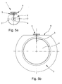
- Fig. 5a shows an embodiment of a sensor assembly 1, mounted in a measuring tube 2 with a small diameter. Since preferably uniform holder 5 and uniform probes 3 are used for all measuring tube diameters, in this embodiment for positioning the probe 3 in the flow cross-section 4 of the measuring tube 2 it is provided that the probes 3 are positioned by two holders 5 stacked one above the other, namely by the greater distance , which is realized by the two holders 5, pulled out of the flow cross-section 4, so that a probe 3 can be used by this adjustment of the penetration depth, which is actually too long for the diameter of the measuring tube 2.
- the holder 5 are geometrically designed so that the holder 5 can engage with its socket 11 both in a recess in the wall 7 of the measuring tube 2 and in a corresponding recess in the top of a second holder 5, so that a problem-free stacking a Plurality of holders 5 is possible.
- Fig. 5b shows, in contrast to the representation in Fig. 5a , An embodiment of a sensor assembly 1, mounted in a measuring tube 2 with a very large diameter, so that the probe 3, which is held by a single holder 5, projects only in the upper region of the flow cross section 4 in this.
- the probe 3 has an identical size as in FIG Fig. 5a shown probe, however, in this embodiment - with a larger Meßrohr penmesser - only a single holder 5 is used for the attachment of the probe 3, since an adjustment of the penetration depth of the probe 3 in this large diameter of the measuring tube 2 is not necessary.
- the embodiment in Fig. 5b additionally has the special feature that in contrast to the embodiment in Fig. 1 in which two probes 3 are arranged one behind the other, only one probe 3 is included in the holder 5, so that the knowledge of a reference temperature or the fluid temperature is necessary for the evaluation of the mass flow with this arrangement.
Landscapes
- Physics & Mathematics (AREA)
- Fluid Mechanics (AREA)
- General Physics & Mathematics (AREA)
- Measuring Volume Flow (AREA)
Applications Claiming Priority (1)
| Application Number | Priority Date | Filing Date | Title |
|---|---|---|---|
| DE102010015813A DE102010015813A1 (de) | 2010-04-20 | 2010-04-20 | Sensoranordnung für ein kalorimetrisches Massedurchflussmessgerät |
Publications (2)
| Publication Number | Publication Date |
|---|---|
| EP2395329A2 true EP2395329A2 (fr) | 2011-12-14 |
| EP2395329A3 EP2395329A3 (fr) | 2012-05-02 |
Family
ID=44358229
Family Applications (1)
| Application Number | Title | Priority Date | Filing Date |
|---|---|---|---|
| EP11002965A Withdrawn EP2395329A3 (fr) | 2010-04-20 | 2011-04-08 | Agencement de capteur pour un appareil de mesure de débit massique calorimétrique |
Country Status (5)
| Country | Link |
|---|---|
| US (1) | US8544352B2 (fr) |
| EP (1) | EP2395329A3 (fr) |
| JP (1) | JP2011227083A (fr) |
| CN (1) | CN102288237A (fr) |
| DE (1) | DE102010015813A1 (fr) |
Families Citing this family (16)
| Publication number | Priority date | Publication date | Assignee | Title |
|---|---|---|---|---|
| US8235592B2 (en) * | 2009-10-07 | 2012-08-07 | Wika Alexander Wiegand Se & Co. Kg | Gauge on a pipe section |
| WO2014136557A1 (fr) * | 2013-03-08 | 2014-09-12 | 株式会社フジキン | Dispositif de commande de fluide et structure pour monter un capteur thermique sur le dispositif de commande de fluide |
| US11181496B2 (en) | 2013-12-06 | 2021-11-23 | Pendotech | Sensor fitting for biotech process bag |
| US10557811B2 (en) | 2013-12-06 | 2020-02-11 | Pendotech | Sensor fitting for biotech process bag |
| US10041896B2 (en) | 2013-12-06 | 2018-08-07 | Pendo TECH | Sensor fitting for biotech process bag |
| DE102013021305B3 (de) | 2013-12-19 | 2014-10-30 | Krohne Messtechnik Gmbh | Schaltungsanordnung zur Temperaturüberwachung und kalorimetrisches Massedurchflussmessgerät |
| US9874464B2 (en) | 2014-12-18 | 2018-01-23 | Wastequip, Llc | Sensor mount |
| DE102015116676A1 (de) * | 2015-01-20 | 2016-07-21 | Krohne Ag | Magnetisch-induktives Durchflussmessgerät und Verfahren zum Herstellen einer Messelektrode |
| US20170108361A1 (en) * | 2015-10-18 | 2017-04-20 | Cdi Meters, Inc. | Target Flowmeter |
| DE102015118120A1 (de) * | 2015-10-23 | 2017-04-27 | Endress + Hauser Flowtec Ag | Thermisches Durchflussmessgerät und Anordnung mit einem Rohr und dem thermischen Durchflussmessgerät |
| US11920984B2 (en) * | 2016-07-14 | 2024-03-05 | Mastrad | Wireless temperature probe |
| DE202016107242U1 (de) * | 2016-12-21 | 2018-03-22 | Nordson Corp. | Sensoreinrichtung zur Bestimmung eines Massenstroms eines flüssigen Heißschmelzklebstoffes |
| JP6793107B2 (ja) * | 2017-11-27 | 2020-12-02 | 日立オートモティブシステムズ株式会社 | 流量計 |
| DE102019115558B3 (de) * | 2019-06-07 | 2020-10-01 | Endress+Hauser Flowtec Ag | Thermisches Durchflussmessgerät |
| WO2020248231A1 (fr) * | 2019-06-14 | 2020-12-17 | Rosemount Inc. | Tube de pitot moyenné à fréquence de résonance réglable |
| US12203812B2 (en) * | 2021-03-01 | 2025-01-21 | Copeland Cold Chain Lp | Bracket for temperature sensor |
Family Cites Families (23)
| Publication number | Priority date | Publication date | Assignee | Title |
|---|---|---|---|---|
| FR1419811A (fr) | 1963-10-19 | 1965-12-03 | Dispositif destiné à larguer automatiquement les ceintures de sécurité pour automobiles | |
| FR1410911A (fr) * | 1964-10-09 | 1965-09-10 | Nat Inst For Res In Nuclear Sc | Appareil pour mesurer un débit massique |
| GB1219710A (en) * | 1969-06-18 | 1971-01-20 | Standard Telephones Cables Ltd | A fluid flowmeter |
| JPS601566B2 (ja) * | 1979-10-17 | 1985-01-16 | 日産自動車株式会社 | カルマン渦流量計 |
| DE3243098A1 (de) * | 1982-11-22 | 1984-05-24 | Rheinische Braunkohlenwerke AG, 5000 Köln | In einen reaktionsbehaelter hineingefuehrtes sondenrohr zur ermittlung des betriebszustandes eines mediums |
| US4480467A (en) | 1982-11-29 | 1984-11-06 | Hyperion, Inc. | Flow monitoring device |
| DE3302080A1 (de) | 1983-01-22 | 1984-07-26 | Leybold-Heraeus GmbH, 5000 Köln | Thermischer massendurchflussmesser, insbesondere fuer gase |
| US4568874A (en) * | 1983-02-17 | 1986-02-04 | Drexelbrook Controls, Inc. | RF Admittance apparatus and method for monitoring the contents of a pipe |
| US4624146A (en) * | 1985-03-05 | 1986-11-25 | Onoda Cement Company, Ltd. | Flow rate measurement apparatus |
| US5437194A (en) * | 1991-03-18 | 1995-08-01 | Panametrics, Inc. | Ultrasonic transducer system with temporal crosstalk isolation |
| US5257532A (en) * | 1992-06-29 | 1993-11-02 | Rutgers, The State University Of New Jersey | Method and apparatus for measuring moisture content as a function of thermal response |
| US5880365A (en) * | 1993-10-29 | 1999-03-09 | Sierra Instruments, Inc. | Thermal mass flow sensor |
| FR2713764B1 (fr) * | 1993-11-10 | 1996-01-12 | Ksb Sa | Dispositif de mesure d'un fluide. |
| US6485175B1 (en) * | 1999-08-06 | 2002-11-26 | Pgi International, Ltd. | Temperature sensing device for metering fluids |
| TW416003B (en) * | 1999-08-20 | 2000-12-21 | Inst Of Nuclear Energy Res Roc | Method and device for void fraction measurement and adverse output signal mitigation on pressure-base instruments |
| US6508134B1 (en) * | 1999-09-01 | 2003-01-21 | Murray F. Feller | Transit-time flow sensor-frequency mode |
| US6827250B2 (en) * | 2001-06-28 | 2004-12-07 | Microchips, Inc. | Methods for hermetically sealing microchip reservoir devices |
| US6802217B2 (en) * | 2001-12-05 | 2004-10-12 | Cdi Meters, Inc. | Flowmeter for compressed-air distribution systems |
| DE10249543A1 (de) * | 2002-10-23 | 2004-05-06 | Endress + Hauser Flowtec Ag, Reinach | Wirbelströmungsaufnehmer |
| US6883389B2 (en) * | 2003-08-21 | 2005-04-26 | Eldridge Products, Inc. | Flow averaging tube and method of using same |
| DE202005013904U1 (de) * | 2005-09-02 | 2006-02-09 | Elb-Form Ges.m.b.H. | Rohr mit Sensoradapter |
| DE202008011995U1 (de) | 2008-09-09 | 2008-11-13 | E.L.B. Füllstandsgeräte Bundschuh GmbH & Co. | Füllstandsmesseinrichtung |
| US20110048564A1 (en) * | 2009-08-25 | 2011-03-03 | Fluid Components International Llc | Fluid flow conditioner |
-
2010
- 2010-04-20 DE DE102010015813A patent/DE102010015813A1/de not_active Withdrawn
- 2010-11-30 US US12/956,346 patent/US8544352B2/en not_active Expired - Fee Related
-
2011
- 2011-04-08 EP EP11002965A patent/EP2395329A3/fr not_active Withdrawn
- 2011-04-20 JP JP2011094139A patent/JP2011227083A/ja not_active Withdrawn
- 2011-04-20 CN CN201110121424XA patent/CN102288237A/zh active Pending
Non-Patent Citations (1)
| Title |
|---|
| None |
Also Published As
| Publication number | Publication date |
|---|---|
| DE102010015813A1 (de) | 2011-10-20 |
| EP2395329A3 (fr) | 2012-05-02 |
| US20110252881A1 (en) | 2011-10-20 |
| CN102288237A (zh) | 2011-12-21 |
| JP2011227083A (ja) | 2011-11-10 |
| US8544352B2 (en) | 2013-10-01 |
Similar Documents
| Publication | Publication Date | Title |
|---|---|---|
| EP2395329A2 (fr) | Agencement de capteur pour un appareil de mesure de débit massique calorimétrique | |
| DE69005884T2 (de) | Massenströmungsmesser mit Temperaturmesssonden. | |
| DE102008015359A1 (de) | Temperatursensor und Verfahren zu dessen Herstellung | |
| EP2491353B1 (fr) | Procédé de mesure du débit et de la direction d'écoulement d'un fluide, et débitmètre du type thermique | |
| EP2574918A1 (fr) | Procédé et capteur microthermiques pour la détermination de propriétés de gaz physiques | |
| DE102014119556A1 (de) | Thermisches Durchflussmessgerät | |
| EP2553413B1 (fr) | Capteur de mesure présentant un boîtier | |
| DE102010040285A1 (de) | Thermisches Durchflussmessgerät | |
| WO2022218649A1 (fr) | Élément de couplage pour un dispositif servant à déterminer et/ou à surveiller une grandeur de processus | |
| EP4052004B1 (fr) | Thermomètre non invasif | |
| DE202016107242U1 (de) | Sensoreinrichtung zur Bestimmung eines Massenstroms eines flüssigen Heißschmelzklebstoffes | |
| DE202013103404U1 (de) | Temperatursensor und Thermisches Durchflussmessgerät | |
| EP2378255B1 (fr) | Dispositif de calibrage pour débitmètres | |
| DE102017128953B4 (de) | Messeinheit zur Erfassung dynamischer Parameter und bzw. oder physikalischer Eigenschaften von strömenden Medien, vorzugsweise von strömenden Fluiden | |
| DE102013203904B3 (de) | Thermoelektrisches Temperaturmessmodul zur Messung der Temperatur in einer Rohrleitung | |
| WO2021063710A1 (fr) | Capteur, tube de mesure, dispositif de mesure et point de mesure de débit volumétrique à induction magnétique | |
| WO2014075905A1 (fr) | Capteur et débitmètre | |
| DE102004058553A1 (de) | Vorrichtung zur Bestimmung und/oder Überwachung des Durchflusses eines Messmediums | |
| DE102012112579A1 (de) | Aufnahmevorrichtung für einen Messeinsatz | |
| DE102012019433A1 (de) | Vorrichtung zur Bestimmung einer Kenngröße eines Mediums | |
| EP0309738B1 (fr) | Robinet-mélangeur régulé par voie électrique | |
| DE102013114483A1 (de) | Temperaturmessvorrichtung | |
| EP2132533A1 (fr) | Appareil de mesure du débit massique thermique présentant des moyens d'élimination du sifflement | |
| DE102013109217B4 (de) | Messsonde zum Messen der elektrischen Leitfähigkeit in gering leitenden Flüssigkeiten | |
| WO2005064285A2 (fr) | Capteur modulaire à tête en forme d'haltère |
Legal Events
| Date | Code | Title | Description |
|---|---|---|---|
| AK | Designated contracting states |
Kind code of ref document: A2 Designated state(s): AL AT BE BG CH CY CZ DE DK EE ES FI FR GB GR HR HU IE IS IT LI LT LU LV MC MK MT NL NO PL PT RO RS SE SI SK SM TR |
|
| AX | Request for extension of the european patent |
Extension state: BA ME |
|
| PUAI | Public reference made under article 153(3) epc to a published international application that has entered the european phase |
Free format text: ORIGINAL CODE: 0009012 |
|
| PUAL | Search report despatched |
Free format text: ORIGINAL CODE: 0009013 |
|
| AK | Designated contracting states |
Kind code of ref document: A3 Designated state(s): AL AT BE BG CH CY CZ DE DK EE ES FI FR GB GR HR HU IE IS IT LI LT LU LV MC MK MT NL NO PL PT RO RS SE SI SK SM TR |
|
| AX | Request for extension of the european patent |
Extension state: BA ME |
|
| RIC1 | Information provided on ipc code assigned before grant |
Ipc: G01F 1/684 20060101AFI20120323BHEP |
|
| 17P | Request for examination filed |
Effective date: 20120925 |
|
| STAA | Information on the status of an ep patent application or granted ep patent |
Free format text: STATUS: THE APPLICATION HAS BEEN WITHDRAWN |
|
| 18W | Application withdrawn |
Effective date: 20140131 |