EP2396244B1 - Überdruckventil für einen verpackungsbehälter - Google Patents
Überdruckventil für einen verpackungsbehälter Download PDFInfo
- Publication number
- EP2396244B1 EP2396244B1 EP20100700839 EP10700839A EP2396244B1 EP 2396244 B1 EP2396244 B1 EP 2396244B1 EP 20100700839 EP20100700839 EP 20100700839 EP 10700839 A EP10700839 A EP 10700839A EP 2396244 B1 EP2396244 B1 EP 2396244B1
- Authority
- EP
- European Patent Office
- Prior art keywords
- relief valve
- pressure relief
- opening
- central
- sealing surface
- Prior art date
- Legal status (The legal status is an assumption and is not a legal conclusion. Google has not performed a legal analysis and makes no representation as to the accuracy of the status listed.)
- Active
Links
Images

Classifications
-
- B—PERFORMING OPERATIONS; TRANSPORTING
- B65—CONVEYING; PACKING; STORING; HANDLING THIN OR FILAMENTARY MATERIAL
- B65D—CONTAINERS FOR STORAGE OR TRANSPORT OF ARTICLES OR MATERIALS, e.g. BAGS, BARRELS, BOTTLES, BOXES, CANS, CARTONS, CRATES, DRUMS, JARS, TANKS, HOPPERS, FORWARDING CONTAINERS; ACCESSORIES, CLOSURES, OR FITTINGS THEREFOR; PACKAGING ELEMENTS; PACKAGES
- B65D77/00—Packages formed by enclosing articles or materials in preformed containers, e.g. boxes, cartons, sacks or bags
- B65D77/22—Details
- B65D77/225—Pressure relief-valves incorporated in a container wall, e.g. valves comprising at least one elastic element
-
- Y—GENERAL TAGGING OF NEW TECHNOLOGICAL DEVELOPMENTS; GENERAL TAGGING OF CROSS-SECTIONAL TECHNOLOGIES SPANNING OVER SEVERAL SECTIONS OF THE IPC; TECHNICAL SUBJECTS COVERED BY FORMER USPC CROSS-REFERENCE ART COLLECTIONS [XRACs] AND DIGESTS
- Y10—TECHNICAL SUBJECTS COVERED BY FORMER USPC
- Y10T—TECHNICAL SUBJECTS COVERED BY FORMER US CLASSIFICATION
- Y10T137/00—Fluid handling
- Y10T137/4238—With cleaner, lubrication added to fluid or liquid sealing at valve interface
- Y10T137/4358—Liquid supplied at valve interface
-
- Y—GENERAL TAGGING OF NEW TECHNOLOGICAL DEVELOPMENTS; GENERAL TAGGING OF CROSS-SECTIONAL TECHNOLOGIES SPANNING OVER SEVERAL SECTIONS OF THE IPC; TECHNICAL SUBJECTS COVERED BY FORMER USPC CROSS-REFERENCE ART COLLECTIONS [XRACs] AND DIGESTS
- Y10—TECHNICAL SUBJECTS COVERED BY FORMER USPC
- Y10T—TECHNICAL SUBJECTS COVERED BY FORMER US CLASSIFICATION
- Y10T137/00—Fluid handling
- Y10T137/7722—Line condition change responsive valves
- Y10T137/7837—Direct response valves [i.e., check valve type]
- Y10T137/7879—Resilient material valve
-
- Y—GENERAL TAGGING OF NEW TECHNOLOGICAL DEVELOPMENTS; GENERAL TAGGING OF CROSS-SECTIONAL TECHNOLOGIES SPANNING OVER SEVERAL SECTIONS OF THE IPC; TECHNICAL SUBJECTS COVERED BY FORMER USPC CROSS-REFERENCE ART COLLECTIONS [XRACs] AND DIGESTS
- Y10—TECHNICAL SUBJECTS COVERED BY FORMER USPC
- Y10T—TECHNICAL SUBJECTS COVERED BY FORMER US CLASSIFICATION
- Y10T137/00—Fluid handling
- Y10T137/7722—Line condition change responsive valves
- Y10T137/7837—Direct response valves [i.e., check valve type]
- Y10T137/7879—Resilient material valve
- Y10T137/7887—Center flexing strip
Definitions
- the present invention relates to a pressure relief valve for a packaging container with significantly improved sealing properties.
- valves for packaging containers are known from the prior art in various configurations.
- the use of valves, in particular flexible packaging for food, is already realized by a variety of technical variants.
- a main requirement of such valves is that they allow only small excess pressures in the packaging by appropriate opening and otherwise reliably prevent the ingress of ambient air. The penetration of ambient air must be prevented even at very low pressures in the packaging.
- the two objectives mentioned above are opposite to each other, since on the one hand only a small opening pressure to open the valve should be present and on the other hand, a high vacuum resistance to be provided. Therefore, valves that have high vacuum resistance also have a very high opening pressure. In contrast, valves with only a small opening pressure do not have the necessary vacuum resistance.
- the pressure relief valve according to the invention for a packaging container with the features of claim 1 has the advantage that it consists of a minimum number of parts and is simple and inexpensive. Furthermore, the pressure relief valve according to the invention on the one hand has a very high vacuum resistance (tightness) and on the other hand makes it possible to open even at small pressure differences between a pressure inside the packaging container and an outside to release this pressure to the outside.
- the pressure relief valve has a base body with a tapered inwardly sealing surface and a membrane which rests on the sealing surface to seal a central passage opening.
- the passage opening has, on its side facing the membrane, an annular bead protruding from a depression in the base body.
- the membrane rests not only on the sealing surface of the body, but also rests on the annular bead around the passage opening around, and thus provides a very secure sealing of the negative pressure in the packaging container.
- a fluid is provided between the diaphragm and the tapered sealing surface, wherein the inwardly tapering shape of the sealing surface ensures that a thickness of the fluid layer between the sealing surface and the diaphragm on an inner side is slightly larger than on an outer side. As a result, larger capillary holding forces are provided on the outer side, which ensure a tighter fit of the membrane on the sealing surface.
- the central passage opening in the base body is tapered.
- the central passage opening tapers in the direction of the interior.
- the central passage opening is conical.
- a level of the annular bead with respect to the inside of the packaging container is below a level of an inner edge of the sealing surface of the base body.
- level is understood as meaning a plane perpendicular to a central axis of the base body, wherein the level is defined starting from a side of the pressure relief valve directed towards the inside of the packaging container.
- the membrane in addition to the flexible properties, also has a deformable surface directed towards the sealing surface.
- a deformation of the surface of the membrane occurs on the sealing surface during the sealing process, which leads to reduced fluid thicknesses between the membrane and the sealing surface.
- the pressure relief valve further comprises an annular circumferential holding device, which is formed integrally with the main body. This holding device prevents the membrane from unexpectedly disengaging from the body.
- the central recess in the main body is formed in two stages with a base recess and a step portion lying on a slightly higher level.
- an outer contour of the base recess is formed such that it corresponds to an outer contour of a figure eight.
- the outer contour of the base recess describes a shape of two intersecting circles, wherein the circles may have the same radii or different radii.
- the deformable surface of the membrane is made of EPDM or NBR or silicone rubber.
- the entire membrane can be made of one of these materials. These materials ensure the necessary flexibility of the membrane as well as the same or deformable surface, while contributing to the improved sealing properties.
- the passage opening on a bottom portion with a perforation introduced therein is arranged at the passage opening.
- a filter element is arranged at the passage opening. Both the perforation and the filter element have the filtering function to prevent small particles from inadvertently getting into the pressure relief valve.
- the edge region of the main body which serves to fix the pressure relief valve on the inside of the packaging container, is formed such that the edge region comprises an inner ring, an outer ring and a middle ring, wherein the center ring protrudes from a base surface further than the inner ring and the outer ring.
- the edge region comprises an inner ring, an outer ring and a middle ring, wherein the center ring protrudes from a base surface further than the inner ring and the outer ring.
- the pressure relief valve according to the invention is preferably used in food packaging, in particular powdery goods, such. Coffee, used.
- FIGS. 1 to 4 a pressure relief valve 1 according to a preferred embodiment of the invention described in detail.
- the pressure relief valve 1 comprises a base body 4 and a membrane 6.
- the base body 4 has a sealing surface 14, which tapers conically inwards in the direction of a central axis XX.
- a fluid 5 is arranged between the sealing surface 14 and the membrane 6 and forms a thin fluid layer. This fluid layer, starting from an outer edge 15 of the sealing surface 14 to an inner edge 16, continuously slightly thicker.
- a filter element 8 is provided in a small recess 8a on a side 7 of the base body 4 directed towards the inside of a packaging in the mounted state.
- the filter element 8 in particular covers a central passage opening 9 and prevents small particles from flowing into the passage opening 9 and thus into the pressure relief valve 1.
- the pressure relief valve 1 is arranged on an inner side 3 a of the package 3.
- a plurality of outlet openings 3b are further formed, the inner mouth area is covered by the pressure relief valve 1 from the inside 3a ago.
- the overpressure valve 1 ensures that no gas or liquid can enter an interior space 2 of the packaging 3 from an outside 11 and also ensures that at an overpressure inside the package 3 this can be discharged via the pressure relief valve 1 to the outside.
- the main body 4 has, in addition to the sealing surface 14, a central recess 30.
- the central recess 30 comprises a base recess 31, which forms a base of the central recess 30, and a step portion 32, which is arranged radially outside the base recess 31.
- a level of the base pit 31 is deeper than a level of the step area 32.
- the term "level” is understood to mean a plane perpendicular to the center axis XX, a definition of a lower level means that this level is closer to the level in the package inwardly directed side 7 of the pressure relief valve 1 is located.
- the central recess 30 and the central passage opening 9 is arranged, wherein, in particular from FIG. 1 it can be seen, the central recess 30 is conically outwardly, ie, in the direction of the membrane 6, expanded.
- a projecting from the base recess 31 annular bead 12 is provided at the mouth region of the central recess 30, a projecting from the base recess 31 annular bead 12 is provided.
- a level of the annular bead 12 is above a level of the step portion 32, but below a level in which the circumferential inner edge 16 is located (see. FIG. 2 ).
- a circumferential outer annular groove 13 is provided radially outside the sealing surface 14. Adjacent to the outer annular groove 13, an edge region 18 is further arranged, by means of which the pressure relief valve 1 is attached to the inside 3a of the package 3. This attachment is preferably carried out by means of an ultrasonic sealing process.
- the edge region 18 has a central ring 19, an outer ring 20 and an inner ring 21.
- the central ring 19 is in relation to a base surface 25 further than the outer ring 20 and the inner ring 21.
- the base surface 25 thus forms recesses between the inner ring 21 and the middle ring 19 and the middle ring 19 and the outer ring 20.
- the particles produced by the fastening method can be absorbed, so that it can be prevented that these particles can fall into an inner region of the pressure relief valve 1.
- FIG. 2 is on a radial inner side of the inner ring 21 a radially to Interior protruding and circumferential retaining ring 22 is formed.
- the retaining ring 22 is also formed integrally with the base body 4 and prevents the membrane 6 unintentionally detached from the base body 4.
- the retaining ring 22 has a hold-down function for the membrane 6.
- the membrane 6 is made of a flexible material and has a soft and deformable surface 6a. This soft and deformable surface 6a is the surface of the membrane 6, which is directed in the direction of the sealing surface 14 of the base body 4.
- an outer contour of the base recess 31 is formed such that this outer contour substantially corresponds to an outer contour of a figure eight. Centric is the central passage opening 9 arranged.
- an improved flow behavior is obtained when the gas is released from the interior 2 of the packaging container 3 to the outside 11.
- the constricting regions 33 of the outer contour allow a directed outflow from the central passage opening 9, so that an opening process of the membrane can be supported. This ensures that the pressure relief valve 1 can open at even lower pressure differences between the interior 2 and the outside 11.
- the function of the pressure relief valve 1 according to the invention is as follows. If a strong vacuum prevails in the interior 2 of the packaging container 3, the pressure relief valve 1 must allow a secure seal against the outside 11. Due to the strong vacuum, the flexible membrane 6 is deformed, so that it applies in a sealing manner on the sealing surface 14 of the base body 4. Furthermore, the deformation can be at a correspondingly low vacuum such that the membrane 6 rests on the annular bead 12.
- the membrane 6 Since the membrane 6 has a soft and deformable surface 6a, there is additionally a deformation at the contact areas, the deformation being slightly stronger at the outer edge 15 than at the inner edge 16 due to the inwardly tapered sealing surface of the sealing surface 14 a thickness of a fluid 5, in particular in the region of the outer edge 15, very low, so that here high capillary forces and Adhesion forces act and ensure a particularly high density.
- the fluid 5 forms a particularly thin film in the region of the outer edge 15.
- the pressure in the interior of the packaging 3 is above a pressure on the outside 11, then this pressure must be released via the internal pressure valve 1 and the through-openings 3b in order to avoid, in particular, swelling of the packaging container 3. If the diaphragm 6 in this case rests on the annular bead 12 for sealing, the pressure force can thus act only on the limited by the inner edge of the annular bead 12 surface. However, since the central passage opening 9 expands conically outward, the pressure in this area increases slightly, so that a slight lifting of the membrane 6 from the annular bead 12 is achieved.
- FIG. 1 shows just an open state of the pressure relief valve 1, wherein the gas from the interior via gaps between the membrane 6 and the edge region 18 can reach into an area 10 between the membrane 6 and the inside 3a of the packaging body and from there via the passage openings 3b to Outside 11.
- a simply constructed pressure relief valve 1 can be provided which consists of only two parts, namely the main body 4 and the membrane 6.
- Arrangement of the central passage opening 9 with the corresponding annular bead 12 can while an improved opening behavior on the one hand and on the other hand, an improved vacuum resistance can be obtained.
Landscapes
- Engineering & Computer Science (AREA)
- Mechanical Engineering (AREA)
- Closures For Containers (AREA)
- Packages (AREA)
- Safety Valves (AREA)
- Details Of Valves (AREA)
Description
- Die vorliegende Erfindung betrifft ein Überdruckventil für einen Verpackungsbehälter mit signifikant verbesserten Dichtungseigenschaften.
- Überdruckventile für Verpackungsbehälter sind aus dem Stand der Technik in unterschiedlichen Ausgestaltungen bekannt. Die Verwendung von Ventilen, insbesondere an flexiblen Verpackungen für Lebensmittel, ist bereits durch eine Vielzahl von technischen Varianten realisiert. Eine Hauptanforderung an derartige Ventile ist, dass sie durch entsprechendes Öffnen nur geringe Überdrücke in der Verpackung zulassen und ansonsten das Eindringen von Umgebungsluft sicher verhindern. Das Eindringen von Umgebungsluft muss dabei auch bei sehr geringen Drücken in der Verpackung verhindert werden. In der Praxis sind die beiden oben genannten Ziele jedoch zueinander gegenläufig, da einerseits ein nur kleiner Öffnungsdruck zum Öffnen des Ventils vorhanden sein soll und andererseits eine hohe Vakuumfestigkeit bereitgestellt werden soll. Daher haben Ventile, die eine hohe Vakuumfestigkeit aufweisen, auch einen sehr hohen Öffnungsdruck. Im Gegensatz dazu haben Ventile mit nur geringem Öffnungsdruck nicht die notwendige Vakuumfestigkeit.
- Aus der
EP 1 802 537 B1 ist ein Überdruckventil bekannt, welches in einer Vertiefung in einem Grundkörper teilweise unplan ausgebildet ist. Hierdurch ergeben sich Zonen unterschiedlichen Abstands zwischen der Vertiefung und einer Ventilmembran. Dieses Ventil hat sich grundsätzlich bewährt, allerdings gibt es in jüngster Zeit verstärkt Anwendungsfälle, welche eine verbesserte Öffnungscharakteristik und Vakuumfestigkeit erfordern. - Das erfindungsgemäße Überdruckventil für einen Verpackungsbehälter mit den Merkmalen des Anspruchs 1 weist demgegenüber den Vorteil auf, dass es aus einer minimalen Teileanzahl besteht und einfach und kostengünstig aufgebaut ist. Ferner weist das erfindungsgemäße Überdruckventil einerseits eine sehr hohe Vakuumfestigkeit (Dichtheit) auf und andererseits ermöglicht es schon bei kleinen Druckunterschieden zwischen einem Druck im Inneren des Verpackungsbehälters und einer Außenseite zu öffnen, um diesen Druck nach außen abzugeben. Dies wird erfindungsgemäß dadurch erreicht, dass das Überdruckventil einen Grundkörper mit einer sich nach innen verjüngenden Dichtfläche sowie eine Membran aufweist, welche auf der Dichtfläche aufliegt, um eine zentrale Durchgangsöffnung abzudichten. Die Durchgangsöffnung weist dabei an ihrer zur Membran gerichteten Seite einen von einer Vertiefung im Grundkörper vorstehenden Ringwulst auf. Hierdurch wird erfindungsgemäß sichergestellt, dass bei einem sehr hohen Unterdruck im Verpackungsbehälter die Membran nicht nur an der Dichtfläche des Grundkörpers anliegt, sondern auch am Ringwulst um die Durchgangsöffnung herum anliegt, und so eine sehr sichere Abdichtung des Unterdrucks im Verpackungsbehälter bereitstellt. Ferner ist ein Fluid zwischen der Membran und der sich verjüngenden Dichtfläche vorgesehen, wobei die sich nach Innen verjüngende Form der Dichtfläche sicherstellt, dass eine Dicke der Fluidschicht zwischen der Dichtfläche und der Membran an einer Inneren Seite etwas größer ist als an einer äußeren Seite. Hierdurch werden an der äußeren Seite größere kapillare Haltekräfte bereitgestellt, welche einen festeren Sitz der Membran auf der Dichtfläche sicherstellen. Dadurch wird einerseits die Dichtigkeit gegenüber einem hohen Unterdruck im Verpackungsbehälter durch die relativ hohen Kräfte an der Außenseite der Dichtfläche sichergestellt und andererseits kann ein leichteres öffnen durch die etwas geringeren Kräfte am Innenbereich der Dichtfläche ermöglicht werden, wobei sich die Öffnungskräfte während des Öffnungsvorgangs aufgrund der sich ständig vergrößernden Membranfläche, die dem Überdruck im Verpackungsbehälter ausgesetzt ist, ständig vergrößern, so dass ein schnelleres Öffnen erreicht wird.
- Die Unteransprüche zeigen bevorzugte Weiterbildungen der Erfindung.
- Vorzugsweise ist die zentrale Durchgangsöffnung im Grundkörper sich verjüngend ausgebildet. Hierdurch kann ein Strömungsverhalten von Gasen, welche aus dem Verpackungsbehälter nach außen abgegeben werden, beeinflusst werden. Besonders bevorzugt verjüngt sich dabei die zentrale Durchgangsöffnung in Richtung des Innenraums. Somit kann erreicht werden, dass eine Diffusorwirkung während der Abströmung von Gas aus dem Inneren des Verpackungsbehälters erhalten wird, so dass ein schnelleres Öffnen bzw. ein Öffnen auch bei nur sehr kleinen Druckunterschieden im Bereich von unter 500 Pa erhalten werden. Vorzugsweise ist die zentrale Durchgangsöffnung dabei konisch ausgebildet.
- Weiter bevorzugt liegt ein Niveau des Ringwulstes bezüglich der Innenseite des Verpackungsbehälters unterhalb einem Niveau einer Innenkante der Dichtfläche des Grundkörpers. Unter Niveau wird hierbei eine Ebene senkrecht zu einer Mittelachse des Grundkörpers verstanden, wobei das Niveau ausgehend von einer zur Innenseite des Verpackungsbehälters gerichteten Seite des Überdruckventils definiert ist.
- Erfindungsgemäss weist die Membran neben den flexiblen Eigenschaften noch eine zur Dichtfläche gerichtete, verformbare Oberfläche auf. Hierdurch wird eine noch bessere Vakuumfestigkeit erreicht, da während des Dichtvorgangs eine Verformung der Oberfläche der Membran an der Dichtfläche auftritt, was zu reduzierten Fluiddicken zwischen Membran und Dichtfläche führt.
- Gemäß einer weiteren bevorzugten Ausgestaltung der Erfindung umfasst das Überdruckventil ferner eine ringförmig umlaufende Haltevorrichtung, welche integral mit dem Grundkörper gebildet ist. Diese Haltevorrichtung verhindert, dass die Membran sich unvorhergesehener Weise vom Grundkörper löst.
- Weiterhin ist die zentrale Vertiefung im Grundkörper erfinungsgemäss, zweistufig mit einer Basisvertiefung und einer auf einem etwas höheren Niveau liegenden Stufenbereich gebildet. Hierbei ist eine Außenkontur der Basisvertiefung derart gebildet, dass sie einer Außenkontur einer Acht entspricht. Mit anderen Worten beschreibt die Außenkontur der Basisvertiefung eine Form zweier sich schneidender Kreise, wobei die Kreise gleiche Radien oder unterschiedliche Radien aufweisen können.
- Vorzugsweise ist die verformbare Oberfläche der Membran aus EPDM oder NBR oder Silikon-Kautschuk hergestellt. Alternativ kann auch die gesamte Membran aus einem dieser Materialien hergestellt sein. Diese Materialien gewährleisten dabei die notwendige Flexibilität der Membran als auch die gleiche bzw. verformbare Oberfläche, während zu den verbesserten Dichteigenschaften beiträgt.
- Gemäß einer weiteren bevorzugten Ausgestaltung der Erfindung weist die Durchgangsöffnung einen Bodenbereich mit einer darin eingebrachten Perforation auf. Alternativ ist an der Durchgangsöffnung ein Filterelement angeordnet. Sowohl die Perforation als auch das Filterelement weisen die Filterfunktion auf, um zu verhindern, dass kleine Partikel unbeabsichtigter Weise in das Überdruckventil gelangen können.
- Bevorzugt ist der Randbereich des Grundkörpers, welcher zur Fixierung des Überdruckventils an der Innenseite des Verpackungsbehälters dient, derart ausgebildet, dass der Randbereich einen Innenring, einen Außenring und einen Mittelring umfasst, wobei der Mittelring von einer Basisfläche weiter vorsteht als der Innenring und der Außenring. Hierdurch kann insbesondere während eines Ultraschall-Siegelvorgangs sichergestellt werden, dass eventuell entstehende Partikel während des Siegelvorgangs nicht in den Innenbereich des Überdruckventils oder zur Außenseite fallen, sondern zwischen den Mittelring und den Außenring bzw. Innenring aufgefangen werden.
- Das erfindungsgemäße Überdruckventil wird vorzugsweise bei Lebensmittelverpackungen, insbesondere von pulverförmigen Gütern, wie z.B. Kaffee, verwendet.
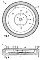
- Nachfolgend wird ein bevorzugtes Ausführungsbeispiel der Erfindung unter Bezugnahme auf die begleitende Zeichnung im Detail beschrieben. In der Zeichnung ist:
- Figur 1
- eine schematische Schnittansicht eines Überdruckventils gemäß einem Ausführungsbeispiel der Erfindung,
- Figur 2
- eine schematische Schnittansicht des in
Figur 1 gezeigten Grundkörpers des Überdruckventils in vergrößerter Darstellung, - Figur 3
- eine schematische Draufsicht des Grundkörpers, und
- Figur 4
- eine schematische Schnittansicht des Grundkörpers.
- Nachfolgend wird unter Bezugnahme auf die
Figuren 1 bis 4 ein Überdruckventil 1 gemäß einem bevorzugten Ausführungsbeispiel der Erfindung im Detail beschrieben. - Wie aus
Figur 1 ersichtlich ist, umfasst das Überdruckventil 1 einen Grundkörper 4 und eine Membran 6. Der Grundkörper 4 weist eine Dichtfläche 14 auf, welche sich konisch nach Innen in Richtung einer Mittelachse X-X verjüngt. Ein Fluid 5 ist zwischen der Dichtfläche 14 und der Membran 6 angeordnet und bildet eine dünne Fluidschicht. Diese Fluidschicht wird, ausgehend von einer Außenkante 15 der Dichtfläche 14 zu einer Innenkante 16, kontinuierlich etwas dicker. - An einer im montierten Zustand zur Innenseite einer Verpackung gerichteten Seite 7 des Grundkörpers 4 ist in einer kleinen Ausnehmung 8a ein Filterelement 8 vorgesehen. Das Filterelement 8 überdeckt insbesondere eine zentrale Durchgangsöffnung 9 und verhindert, dass kleine Partikel in die Durchgangsöffnung 9 und somit in das Überdruckventil 1 strömen können.
- Das Überdruckventil 1 ist an einer Innenseite 3a der Verpackung 3 angeordnet. In der Verpackung 3 sind ferner mehrere Auslassöffnungen 3b gebildet, deren innerer Mündungsbereich durch das Überdruckventil 1 von der Innenseite 3a her überdeckt wird. Das Überdruckventil 1 stellt dabei einerseits sicher, dass von einer Außenseite 11 kein Gas oder keine Flüssigkeit in einen Innenraum 2 der Verpackung 3 gelangen kann und stellt ferner sicher, dass bei einem Überdruck im Inneren der Verpackung 3 dieser über das Überdruckventil 1 nach außen abgegeben werden kann.
- Der Grundkörper 4 weist neben der Dichtfläche 14 eine zentrale Vertiefung 30 auf. Die zentrale Vertiefung 30 umfasst eine Basisvertiefung 31, welche eine Grundfläche der zentralen Vertiefung 30 bildet und einen Stufenbereich 32, welcher radial außerhalb der Basisvertiefung 31 angeordnet ist. Hierbei ist ein Niveau der Basisvertiefung 31 tiefer als ein Niveau des Stufenbereichs 32. Es sei angemerkt, dass unter dem Begriff "Niveau" eine Ebene senkrecht zur Mittelachse X-X verstanden werden soll, wobei eine Definition eines tieferen Niveaus bedeutet, dass dieses Niveau näher zu der in der Verpackung nach Innen gerichteten Seite 7 des Überdruckventils 1 liegt.
- In der zentralen Vertiefung 30 ist auch die zentrale Durchgangsöffnung 9 angeordnet, wobei, wie insbesondere aus
Figur 1 ersichtlich ist, die zentrale Vertiefung 30 sich konisch nach außen, d.h., in Richtung der Membran 6, erweitert. Am Mündungsbereich der zentralen Vertiefung 30 ist ein von der Basisvertiefung 31 vorstehender Ringwulst 12 vorgesehen. Ein Niveau des Ringwulstes 12 liegt dabei über einem Niveau des Stufenbereichs 32, jedoch unterhalb eines Niveaus, in welchem die umlaufende Innenkante 16 liegt (vgl.Figur 2 ). - Ferner ist radial außerhalb der Dichtfläche 14 eine umlaufende äußere Ringnut 13 vorgesehen. Benachbart zur äußeren Ringnut 13 ist ferner ein Randbereich 18 angeordnet, mittels welchem das Überdruckventil 1 an der Innenseite 3a der Verpackung 3 befestigt wird. Diese Befestigung erfolgt vorzugsweise mittels einem Ultraschall-Siegelverfahren. Wie aus
Figur 2 ersichtlich ist, weist der Randbereich 18 einen Mittelring 19, einen Außenring 20 und einen Innenring 21 auf. Der Mittelring 19 steht dabei bezüglich einer Basisfläche 25 weiter vor als der Außenring 20 und der Innenring 21. Die Basisfläche 25 bildet somit Vertiefungen zwischen dem Innenring 21 und dem Mittelring 19 sowie dem Mittelring 19 und dem Außenring 20. In diese Vertiefungen können dabei eventuell während des Befestigungsverfahrens erzeugte Partikel aufgenommen werden, so dass verhindert werden kann, dass diese Partikel in einen Innenbereich des Überdruckventils 1 fallen können. Wie weiter ausFigur 2 ersichtlich ist, ist an einer radialen Innenseite des Innenrings 21 ein radial nach Innen vorstehender und umlaufender Haltering 22 ausgebildet. Der Haltering 22 ist ebenfalls integral mit dem Grundkörper 4 gebildet und verhindert, dass sich die Membran 6 unbeabsichtigt vom Grundkörper 4 löst. Somit weist der Haltering 22 eine Niederhaltefunktion für die Membran 6 auf. - Die Membran 6 ist aus einem flexiblen Material hergestellt und weist eine weiche und verformbare Oberfläche 6a auf. Diese weiche und verformbare Oberfläche 6a ist dabei die Oberfläche der Membran 6, welche in Richtung der Dichtfläche 14 des Grundkörpers 4 gerichtet ist.
- Wie weiter aus
Figur 3 ersichtlich ist, ist eine Außenkontur der Basisvertiefung 31 derart gebildet, dass diese Außenkontur im Wesentlichen eine Außenkontur einer Acht entspricht. Zentrisch ist dabei die zentrale Durchgangsöffnung 9 angeordnet. Durch diese Ausbildung der Außenkontur der Basisvertiefung 31 in Form einer Acht wird ein verbessertes Strömungsverhalten bei einer Gasabgabe aus dem Innenraum 2 des Verpackungsbehälters 3 zur Außenseite 11 erhalten. Die einschnürenden Bereiche 33 der Außenkontur ermöglichen dabei eine gerichtete Abströmung aus der zentralen Durchgangsöffnung 9, so dass ein Öffnungsvorgang der Membran unterstützt werden kann. Hierdurch wird erreicht, dass das Überdruckventil 1 bei noch geringeren Druckunterschieden zwischen dem Innenraum 2 und der Außenseite 11 öffnen kann. - Die Funktion des erfindungsgemäßen Überdruckventils 1 ist dabei wie folgt. Wenn ein starkes Vakuum in den Innenraum 2 des Verpackungsbehälters 3 herrscht, muss das Überdruckventil 1 eine sichere Abdichtung gegenüber der Außenseite 11 ermöglichen. Durch das starke Vakuum wird die flexible Membran 6 verformt, so dass sie sich in abdichtender Weise an der Dichtfläche 14 des Grundkörpers 4 anlegt. Ferner kann die Verformung bei einem entsprechend tiefen Vakuum derart sein, dass die Membran 6 auch auf dem Ringwulst 12 aufliegt. Da die Membran 6 eine weiche und verformbare Oberfläche 6a aufweist, erfolgt zusätzlich noch eine Verformung an den Kontaktbereichen, wobei die Verformung durch die sich nach Innen verjüngende Dichtfläche der Dichtfläche 14 an der Außenkante 15 noch etwas stärker ist als an der Innenkante 16. Dadurch wird eine Dicke eines Fluids 5, insbesondere im Bereich der Außenkante 15, sehr gering, so dass hier hohe kapillare Kräfte und Adhäsionskräfte wirken und eine besonders hohe Dichtheit gewährleisten. Das Fluid 5 bildet dabei einen besonders dünnen Film im Bereich der Außenkante 15.
- Liegt der Druck im Inneren der Verpackung 3 über einem Druck an der Außenseite 11, so muss dieser Druck über das Innendruckventil 1 und die Durchgangsöffnungen 3b abgegeben werden, um insbesondere ein Aufblähen des Verpackungsbehälters 3 zu vermeiden. Bei einem Überdruck im Innenraum 2 wirkt somit eine Druckkraft auf die Innenseite der Membran 6. Wenn die Membran 6 hierbei zur Abdichtung auf dem Ringwulst 12 aufliegt, kann die Druckkraft somit nur über die durch die Innenkante des Ringwulstes 12 begrenzte Fläche wirken. Da die zentrale Durchgangsöffnung 9 jedoch sich konisch nach außen erweitert, steigt der Druck in diesem Bereich etwas an, so dass ein leichtes Abheben der Membran 6 vom Ringwulst 12 erreicht wird. Da aufgrund der sich verjüngenden Anordnung der Dichtfläche 14 ferner die kapillaren bzw. adhäsiven Kräfte der Fluidschicht im Bereich der Innenkante 16 etwas geringer sind, kann, da der Druck nun auf eine größere Fläche der Membran 6 wirken kann (nämlich die Dichtfläche, welche durch die Innenkante 16 definiert wird), das Überdruckventil öffnen, wenn die resultierenden Druckkräfte auf die Membran 6 größer sind als die kapillaren bzw. adhäsiven Kräfte, die die Membran 6 auf der Dichtfläche 14 halten. Somit sind nur vergleichsweise kleine Druckkräfte erforderlich, um die kapillaren Kräfte im Bereich der Innenkante 16 zu überwinden. Aufgrund der Flexibilität der Membran 6 vergrößert sich dadurch weiter die Angriffsfläche, so dass dann der innere Überdruck immer auf eine größer werdende Fläche der Membran 6 wirken kann und ein Öffnungsvorgang dementsprechend schneller ausgeführt wird.
Figur 1 zeigt dabei gerade einen geöffneten Zustand des Überdruckventils 1, wobei das Gas aus dem Innenraum über Spalte zwischen der Membran 6 und den Randbereich 18 in einen Bereich 10 zwischen der Membran 6 und der Innenseite 3a des Verpackungskörpers gelangen kann und von dort über die Durchlassöffnungen 3b zur Außenseite 11. - Somit kann erfindungsgemäß ein einfach aufgebautes Überdruckventil 1 bereitgestellt werden, welches nur aus zwei Teilen, nämlich dem Grundkörper 4 und der Membran 6 besteht. Durch die erfindungsgemäße. Anordnung der zentralen Durchgangsöffnung 9 mit dem entsprechenden Ringwulst 12 kann dabei ein verbessertes Öffnungsverhalten einerseits und andererseits auch eine verbesserte Vakuumfestigkeit erhalten werden.
Claims (8)
- Überdruckventil für einen Verpackungsbehälter (3), umfassend- einen Grundkörper (4) mit einer Dichtfläche (14) und einem Randbereich (18), wobei der Randbereich (18) mit einer Innenseite (3a) des Verpackungsbehälters (3) abdichtend verbindbar ist und wobei die Dichtfläche (14) eine sich nach Innen verjüngende Form aufweist, und- eine Membran (6), welche auf der Dichtfläche (14) aufliegt, um eine Abdichtung zu ermöglichen, wobei ein Fluid (5) zwischen der Dichtfläche (14) und der Membran (6) angeordnet ist,- wobei die Membran (6) flexibel ist und wobei im Grundkörper (4) eine Vertiefung (30) ausgebildet ist,
dadurch gekennzeichnet, dass- der Grundkörper (4) eine zentrale Durchgangsöffnung (9) aufweist, wobei die zentrale Durchgangsöffnung (9) in die Vertiefung (30) mündet und wobei am Mündungsbereich der zentralen Durchgangsöffnung (9) ein in Richtung der Membran (6) vorstehender Ringwulst (12) angeordnet ist, welcher in die Vertiefung (30) vorsteht,- die Membran (6) eine zur Dichtfläche (14) gerichtete, verformbare Oberfläche (6a) aufweist, und- die Vertiefung (30) zweistufig mit einer Basisvertiefung (31) und einem Stufenbereich (32) gebildet ist, wobei eine Außenkontur der Basisvertiefung (31) im Wesentlichen einer Außenkontur einer Acht entspricht. - Überdruckventil nach Anspruch 1, dadurch gekennzeichnet, dass die zentrale Durchgangsöffnung (9) sich verjüngend, insbesondere konisch, ausgebildet ist.
- Überdruckventil nach Anspruch 2, dadurch gekennzeichnet, dass die zentrale Durchgangsöffnung (9) sich in Richtung einer zum Innenraum (2) gerichteten Seite (7) verjüngt.
- Überdruckventil nach einem der vorhergehenden Ansprüche, dadurch gekennzeichnet, dass ein Niveau des Ringwulstes (12) senkrecht zu einer Mittelachse (X-X) bezüglich der Innenseite (3a) des Verpackungsbehälters unterhalb einem Niveau einer Innenkante (16) der Dichtfläche (14) senkrecht zu einer Mittelachse (X-X) liegt.
- Überdruckventil nach einem der vorhergehenden Ansprüche, ferner umfassend eine ringförmige Haltevorrichtung (22), welche integral mit dem Grundkörper (4) gebildet ist.
- Überdruckventil nach einem der Ansprüche 1 oder 5, dadurch gekennzeichnet, dass die Membran (6) eine Oberfläche aus EPDM oder NBR oder Silikon-Kautschuk aufweist oder dass die Membran (6) vollständig aus einem dieser Materialien hergestellt ist.
- Überdruckventil nach einem der vorhergehenden Ansprüche, dadurch gekennzeichnet, dass die zentrale Durchgangsöffnung (9) einen Bodenbereich mit darin eingebrachter Perforation umfasst oder dass die zentrale Durchgangsöffnung (9) mittels eines Filterelements (8) abgedeckt ist.
- Überdruckventil nach einem der vorhergehenden Ansprüche, dadurch gekennzeichnet, dass der Randbereich (18) des Grundkörpers (4) vor einem Siegelvorgang an den Verpackungsbehälter (3) einen Innenring (21), einen Außenring (20) und einen Mittelring (19) aufweist, wobei der Mittelring (19) von einer Basisfläche (25) weiter nach Außen vorsteht als der Innenring (21) und der Außenring (20).
Applications Claiming Priority (2)
| Application Number | Priority Date | Filing Date | Title |
|---|---|---|---|
| DE200910000802 DE102009000802A1 (de) | 2009-02-12 | 2009-02-12 | Überdruckventil für einen Verpackungsbehälter |
| PCT/EP2010/050211 WO2010091908A1 (de) | 2009-02-12 | 2010-01-11 | Überdruckventil für einen verpackungsbehälter |
Publications (2)
| Publication Number | Publication Date |
|---|---|
| EP2396244A1 EP2396244A1 (de) | 2011-12-21 |
| EP2396244B1 true EP2396244B1 (de) | 2013-06-19 |
Family
ID=41809271
Family Applications (1)
| Application Number | Title | Priority Date | Filing Date |
|---|---|---|---|
| EP20100700839 Active EP2396244B1 (de) | 2009-02-12 | 2010-01-11 | Überdruckventil für einen verpackungsbehälter |
Country Status (5)
| Country | Link |
|---|---|
| US (1) | US8555925B2 (de) |
| EP (1) | EP2396244B1 (de) |
| CN (1) | CN102317174B (de) |
| DE (1) | DE102009000802A1 (de) |
| WO (1) | WO2010091908A1 (de) |
Cited By (4)
| Publication number | Priority date | Publication date | Assignee | Title |
|---|---|---|---|---|
| DE102019200860A1 (de) | 2019-01-24 | 2020-07-30 | Syntegon Technology Gmbh | Überdruckventil mit schwimmender Membran |
| DE102019200867A1 (de) | 2019-01-24 | 2020-07-30 | Syntegon Technology Gmbh | Vakuumfestes Überdruckventil für Verpackungsbehälter |
| WO2021053150A1 (de) | 2019-09-19 | 2021-03-25 | Syntegon Technology Gmbh | Ventil für einen verpackungsbehälter |
| WO2021053149A1 (de) | 2019-09-19 | 2021-03-25 | Syntegon Technology Gmbh | Ventil für einen verpackungsbehälter |
Families Citing this family (10)
| Publication number | Priority date | Publication date | Assignee | Title |
|---|---|---|---|---|
| EP2893230B1 (de) * | 2013-05-16 | 2016-10-12 | O2I Ltd. | Regelungsvorrichtung für ein durch druck aktiviertes einwegventil |
| TWI580878B (zh) * | 2016-07-19 | 2017-05-01 | 科際精密股份有限公司 | 單向閥組件 |
| TWI640707B (zh) * | 2017-07-21 | 2018-11-11 | 陳家珍 | 排氣閥 |
| TWI649238B (zh) * | 2018-02-05 | 2019-02-01 | 川本國際包裝有限公司 | 包裝袋保鮮排氣閥結構 |
| CN109757949B (zh) * | 2019-03-14 | 2021-05-07 | 惠东县港东塑胶制品有限公司 | 一种碳酸饮料杯 |
| WO2021021578A1 (en) * | 2019-07-26 | 2021-02-04 | Lam Research Corporation | Non-elastomeric, non-polymeric, non-metallic membrane valves for semiconductor processing equipment |
| DE102021106903A1 (de) | 2021-03-19 | 2022-09-22 | Konzelmann Gmbh | Druckausgleichsvorrichtung |
| IT202200004763A1 (it) * | 2022-03-11 | 2023-09-11 | Goglio Spa | Valvola di degassazione per un contenitore ermetico |
| EP4257511A1 (de) * | 2022-04-08 | 2023-10-11 | B&T Entwicklungs- und Vermarktungsgesellschaft mbH | Ventil und verpackung |
| CN116853681A (zh) * | 2023-07-05 | 2023-10-10 | 苏州安洁科技股份有限公司 | 一种非平面产品的包装结构 |
Family Cites Families (11)
| Publication number | Priority date | Publication date | Assignee | Title |
|---|---|---|---|---|
| FR1360753A (fr) * | 1963-03-11 | 1964-05-15 | Perfectionnement aux sachets et autres récipients analogues comportant une soupape en matière plastique | |
| DE4129838A1 (de) | 1991-02-16 | 1992-08-20 | Bosch Gmbh Robert | Ueberdruckventil fuer verpackungsbehaelter |
| US5992442A (en) * | 1997-05-29 | 1999-11-30 | Urquhart; Edward F. | Relief valve for use with hermetically sealed flexible container |
| DE19843430A1 (de) * | 1998-09-22 | 2000-03-23 | Wipf Ag Volketswil | Staubdichter Beutel für feinpulvrige Produkte |
| DE19844343A1 (de) * | 1998-09-27 | 2000-06-15 | Schwindt Rudolf | Potenztropfen aus Chol |
| DE10256245A1 (de) | 2002-12-02 | 2004-06-09 | Robert Bosch Gmbh | Überdruckventil für einen Verpackungsbehälter |
| WO2005036983A2 (en) * | 2003-10-16 | 2005-04-28 | Pouch Pac Innovations, Llc. | Packaging release valve for microwavable food items |
| DE102004062026A1 (de) | 2004-09-29 | 2006-03-30 | Robert Bosch Gmbh | Überdruckventil für einen Verpackungsbehälter |
| US8925579B2 (en) * | 2006-03-02 | 2015-01-06 | Pacific Bag, Inc. | Pressure relief valve |
| ITBO20060856A1 (it) * | 2006-12-15 | 2008-06-16 | Aroma System Srl | Valvola di sfiato unidirezionale di tipo piatto. |
| US8888470B2 (en) * | 2007-02-27 | 2014-11-18 | Deka Products Limited Partnership | Pumping cassette |
-
2009
- 2009-02-12 DE DE200910000802 patent/DE102009000802A1/de not_active Withdrawn
-
2010
- 2010-01-11 US US13/148,973 patent/US8555925B2/en active Active
- 2010-01-11 CN CN201080007717.9A patent/CN102317174B/zh active Active
- 2010-01-11 EP EP20100700839 patent/EP2396244B1/de active Active
- 2010-01-11 WO PCT/EP2010/050211 patent/WO2010091908A1/de not_active Ceased
Cited By (7)
| Publication number | Priority date | Publication date | Assignee | Title |
|---|---|---|---|---|
| DE102019200860A1 (de) | 2019-01-24 | 2020-07-30 | Syntegon Technology Gmbh | Überdruckventil mit schwimmender Membran |
| DE102019200867A1 (de) | 2019-01-24 | 2020-07-30 | Syntegon Technology Gmbh | Vakuumfestes Überdruckventil für Verpackungsbehälter |
| WO2021053150A1 (de) | 2019-09-19 | 2021-03-25 | Syntegon Technology Gmbh | Ventil für einen verpackungsbehälter |
| WO2021053149A1 (de) | 2019-09-19 | 2021-03-25 | Syntegon Technology Gmbh | Ventil für einen verpackungsbehälter |
| DE102019214315A1 (de) * | 2019-09-19 | 2021-03-25 | Syntegon Technology Gmbh | Ventil für einen Verpackungsbehälter |
| US11939133B2 (en) | 2019-09-19 | 2024-03-26 | Syntegon Technology Gmbh | Valve for a packaging container |
| US12252322B2 (en) | 2019-09-19 | 2025-03-18 | Syntegon Technology Gmbh | Valve for a packaging container |
Also Published As
| Publication number | Publication date |
|---|---|
| US8555925B2 (en) | 2013-10-15 |
| WO2010091908A1 (de) | 2010-08-19 |
| DE102009000802A1 (de) | 2010-08-19 |
| EP2396244A1 (de) | 2011-12-21 |
| CN102317174B (zh) | 2014-01-01 |
| CN102317174A (zh) | 2012-01-11 |
| US20120048853A1 (en) | 2012-03-01 |
Similar Documents
| Publication | Publication Date | Title |
|---|---|---|
| EP2396244B1 (de) | Überdruckventil für einen verpackungsbehälter | |
| DE10205344B4 (de) | Hermetisch verschlossener Behälter mit durchstechbarem Zugangseinlass | |
| EP3292575B1 (de) | Gehäuse mit überdrucksicherung | |
| CH642863A5 (de) | Filtereinheit zum entgasen einer fluessigkeit und ablassen des gases sowie verfahren zur herstellung der einheit. | |
| EP0601491A1 (de) | Verschlussmittel und Dichtungsventil für Behälteröffnungen | |
| EP0612537A2 (de) | Rückschlagventil, insbesondere für medizinische Anwendungen der Fluidtechnik | |
| DE102015005692A1 (de) | Druckregelventil | |
| EP1802537B1 (de) | Überdruckventil für einen verpackungsbehälter | |
| EP3204676A1 (de) | Absperrkörper für ein ventil und ventil mit einem derartigen absperrkörper | |
| EP2396242B1 (de) | Überdruckventil mit kleinen abmessungen | |
| DE102021001258B4 (de) | Ventil zum Druckausgleich und/oder zur Notentlüftung eines Behälters, vorzugsweise eines Gehäuses einer Fahrzeugbatterie, sowie Behälter mit einem solchen Ventil | |
| EP2396243B1 (de) | Überdruckventil für einen verpackungsbehälter | |
| EP1918620A2 (de) | Rückschlagventil, insbesondere für medizinische Anwendungen | |
| EP2027885B1 (de) | Rückschlagventil, insbesondere für medizinische Anwendungen | |
| EP3686125B1 (de) | Überdruckventil mit schwimmender membran und verpackungsbehälter | |
| EP3686124B1 (de) | Vakuumfestes überdruckventil für verpackungsbehälter | |
| DE10349395B3 (de) | Vorrichtung zum Abdichten einer Behälteröffnung | |
| EP4094550A1 (de) | Gehäuse mit einer druckausgleichseinrichtung | |
| EP4562713A1 (de) | Druckausgleichsvorrichtung | |
| DE102017103133B4 (de) | Verschluss für einen Behälter zur Aufnahme und Abgabe von Flüssigkeiten | |
| DE102006018989A1 (de) | Dreiwege-Rückschlagventil | |
| DE202007006579U1 (de) | Axialdichtung für den Ventilkörper-Dichtsitz eines Be- und Entlüftungsventils | |
| DE7218333U (de) | Einsatzventil zum Einsetzen in einem aufblasbaren Körper | |
| DE202010007614U1 (de) | Sicherheitsventil | |
| DE102006029820A1 (de) | Vorrichtung zur Messung von Meßgrößen |
Legal Events
| Date | Code | Title | Description |
|---|---|---|---|
| PUAI | Public reference made under article 153(3) epc to a published international application that has entered the european phase |
Free format text: ORIGINAL CODE: 0009012 |
|
| 17P | Request for examination filed |
Effective date: 20110912 |
|
| AK | Designated contracting states |
Kind code of ref document: A1 Designated state(s): AT BE BG CH CY CZ DE DK EE ES FI FR GB GR HR HU IE IS IT LI LT LU LV MC MK MT NL NO PL PT RO SE SI SK SM TR |
|
| DAX | Request for extension of the european patent (deleted) | ||
| GRAP | Despatch of communication of intention to grant a patent |
Free format text: ORIGINAL CODE: EPIDOSNIGR1 |
|
| GRAS | Grant fee paid |
Free format text: ORIGINAL CODE: EPIDOSNIGR3 |
|
| GRAA | (expected) grant |
Free format text: ORIGINAL CODE: 0009210 |
|
| AK | Designated contracting states |
Kind code of ref document: B1 Designated state(s): AT BE BG CH CY CZ DE DK EE ES FI FR GB GR HR HU IE IS IT LI LT LU LV MC MK MT NL NO PL PT RO SE SI SK SM TR |
|
| REG | Reference to a national code |
Ref country code: GB Ref legal event code: FG4D Free format text: NOT ENGLISH |
|
| REG | Reference to a national code |
Ref country code: CH Ref legal event code: EP |
|
| REG | Reference to a national code |
Ref country code: AT Ref legal event code: REF Ref document number: 617517 Country of ref document: AT Kind code of ref document: T Effective date: 20130715 |
|
| REG | Reference to a national code |
Ref country code: IE Ref legal event code: FG4D Free format text: LANGUAGE OF EP DOCUMENT: GERMAN |
|
| REG | Reference to a national code |
Ref country code: DE Ref legal event code: R096 Ref document number: 502010003715 Country of ref document: DE Effective date: 20130814 |
|
| PG25 | Lapsed in a contracting state [announced via postgrant information from national office to epo] |
Ref country code: SI Free format text: LAPSE BECAUSE OF FAILURE TO SUBMIT A TRANSLATION OF THE DESCRIPTION OR TO PAY THE FEE WITHIN THE PRESCRIBED TIME-LIMIT Effective date: 20130619 Ref country code: ES Free format text: LAPSE BECAUSE OF FAILURE TO SUBMIT A TRANSLATION OF THE DESCRIPTION OR TO PAY THE FEE WITHIN THE PRESCRIBED TIME-LIMIT Effective date: 20130930 Ref country code: LT Free format text: LAPSE BECAUSE OF FAILURE TO SUBMIT A TRANSLATION OF THE DESCRIPTION OR TO PAY THE FEE WITHIN THE PRESCRIBED TIME-LIMIT Effective date: 20130619 Ref country code: SE Free format text: LAPSE BECAUSE OF FAILURE TO SUBMIT A TRANSLATION OF THE DESCRIPTION OR TO PAY THE FEE WITHIN THE PRESCRIBED TIME-LIMIT Effective date: 20130619 Ref country code: FI Free format text: LAPSE BECAUSE OF FAILURE TO SUBMIT A TRANSLATION OF THE DESCRIPTION OR TO PAY THE FEE WITHIN THE PRESCRIBED TIME-LIMIT Effective date: 20130619 Ref country code: NO Free format text: LAPSE BECAUSE OF FAILURE TO SUBMIT A TRANSLATION OF THE DESCRIPTION OR TO PAY THE FEE WITHIN THE PRESCRIBED TIME-LIMIT Effective date: 20130919 Ref country code: GR Free format text: LAPSE BECAUSE OF FAILURE TO SUBMIT A TRANSLATION OF THE DESCRIPTION OR TO PAY THE FEE WITHIN THE PRESCRIBED TIME-LIMIT Effective date: 20130920 |
|
| REG | Reference to a national code |
Ref country code: LT Ref legal event code: MG4D |
|
| PG25 | Lapsed in a contracting state [announced via postgrant information from national office to epo] |
Ref country code: HR Free format text: LAPSE BECAUSE OF FAILURE TO SUBMIT A TRANSLATION OF THE DESCRIPTION OR TO PAY THE FEE WITHIN THE PRESCRIBED TIME-LIMIT Effective date: 20130619 Ref country code: BG Free format text: LAPSE BECAUSE OF FAILURE TO SUBMIT A TRANSLATION OF THE DESCRIPTION OR TO PAY THE FEE WITHIN THE PRESCRIBED TIME-LIMIT Effective date: 20130919 |
|
| REG | Reference to a national code |
Ref country code: NL Ref legal event code: VDEP Effective date: 20130619 |
|
| PG25 | Lapsed in a contracting state [announced via postgrant information from national office to epo] |
Ref country code: LV Free format text: LAPSE BECAUSE OF FAILURE TO SUBMIT A TRANSLATION OF THE DESCRIPTION OR TO PAY THE FEE WITHIN THE PRESCRIBED TIME-LIMIT Effective date: 20130619 |
|
| PG25 | Lapsed in a contracting state [announced via postgrant information from national office to epo] |
Ref country code: SK Free format text: LAPSE BECAUSE OF FAILURE TO SUBMIT A TRANSLATION OF THE DESCRIPTION OR TO PAY THE FEE WITHIN THE PRESCRIBED TIME-LIMIT Effective date: 20130619 Ref country code: PT Free format text: LAPSE BECAUSE OF FAILURE TO SUBMIT A TRANSLATION OF THE DESCRIPTION OR TO PAY THE FEE WITHIN THE PRESCRIBED TIME-LIMIT Effective date: 20131021 Ref country code: EE Free format text: LAPSE BECAUSE OF FAILURE TO SUBMIT A TRANSLATION OF THE DESCRIPTION OR TO PAY THE FEE WITHIN THE PRESCRIBED TIME-LIMIT Effective date: 20130619 Ref country code: CZ Free format text: LAPSE BECAUSE OF FAILURE TO SUBMIT A TRANSLATION OF THE DESCRIPTION OR TO PAY THE FEE WITHIN THE PRESCRIBED TIME-LIMIT Effective date: 20130619 Ref country code: IS Free format text: LAPSE BECAUSE OF FAILURE TO SUBMIT A TRANSLATION OF THE DESCRIPTION OR TO PAY THE FEE WITHIN THE PRESCRIBED TIME-LIMIT Effective date: 20131019 Ref country code: CY Free format text: LAPSE BECAUSE OF FAILURE TO SUBMIT A TRANSLATION OF THE DESCRIPTION OR TO PAY THE FEE WITHIN THE PRESCRIBED TIME-LIMIT Effective date: 20130731 |
|
| PG25 | Lapsed in a contracting state [announced via postgrant information from national office to epo] |
Ref country code: RO Free format text: LAPSE BECAUSE OF FAILURE TO SUBMIT A TRANSLATION OF THE DESCRIPTION OR TO PAY THE FEE WITHIN THE PRESCRIBED TIME-LIMIT Effective date: 20130619 Ref country code: PL Free format text: LAPSE BECAUSE OF FAILURE TO SUBMIT A TRANSLATION OF THE DESCRIPTION OR TO PAY THE FEE WITHIN THE PRESCRIBED TIME-LIMIT Effective date: 20130619 Ref country code: NL Free format text: LAPSE BECAUSE OF FAILURE TO SUBMIT A TRANSLATION OF THE DESCRIPTION OR TO PAY THE FEE WITHIN THE PRESCRIBED TIME-LIMIT Effective date: 20130619 |
|
| PG25 | Lapsed in a contracting state [announced via postgrant information from national office to epo] |
Ref country code: CY Free format text: LAPSE BECAUSE OF FAILURE TO SUBMIT A TRANSLATION OF THE DESCRIPTION OR TO PAY THE FEE WITHIN THE PRESCRIBED TIME-LIMIT Effective date: 20130619 |
|
| PLBE | No opposition filed within time limit |
Free format text: ORIGINAL CODE: 0009261 |
|
| STAA | Information on the status of an ep patent application or granted ep patent |
Free format text: STATUS: NO OPPOSITION FILED WITHIN TIME LIMIT |
|
| PG25 | Lapsed in a contracting state [announced via postgrant information from national office to epo] |
Ref country code: DK Free format text: LAPSE BECAUSE OF FAILURE TO SUBMIT A TRANSLATION OF THE DESCRIPTION OR TO PAY THE FEE WITHIN THE PRESCRIBED TIME-LIMIT Effective date: 20130619 |
|
| 26N | No opposition filed |
Effective date: 20140320 |
|
| PGFP | Annual fee paid to national office [announced via postgrant information from national office to epo] |
Ref country code: FR Payment date: 20140124 Year of fee payment: 5 |
|
| REG | Reference to a national code |
Ref country code: DE Ref legal event code: R097 Ref document number: 502010003715 Country of ref document: DE Effective date: 20140320 |
|
| BERE | Be: lapsed |
Owner name: ROBERT BOSCH G.M.B.H. Effective date: 20140131 |
|
| PG25 | Lapsed in a contracting state [announced via postgrant information from national office to epo] |
Ref country code: LU Free format text: LAPSE BECAUSE OF FAILURE TO SUBMIT A TRANSLATION OF THE DESCRIPTION OR TO PAY THE FEE WITHIN THE PRESCRIBED TIME-LIMIT Effective date: 20140111 |
|
| REG | Reference to a national code |
Ref country code: CH Ref legal event code: PL |
|
| GBPC | Gb: european patent ceased through non-payment of renewal fee |
Effective date: 20140111 |
|
| PG25 | Lapsed in a contracting state [announced via postgrant information from national office to epo] |
Ref country code: LI Free format text: LAPSE BECAUSE OF NON-PAYMENT OF DUE FEES Effective date: 20140131 Ref country code: CH Free format text: LAPSE BECAUSE OF NON-PAYMENT OF DUE FEES Effective date: 20140131 |
|
| REG | Reference to a national code |
Ref country code: IE Ref legal event code: MM4A |
|
| PG25 | Lapsed in a contracting state [announced via postgrant information from national office to epo] |
Ref country code: GB Free format text: LAPSE BECAUSE OF NON-PAYMENT OF DUE FEES Effective date: 20140111 |
|
| PG25 | Lapsed in a contracting state [announced via postgrant information from national office to epo] |
Ref country code: BE Free format text: LAPSE BECAUSE OF NON-PAYMENT OF DUE FEES Effective date: 20140131 Ref country code: IE Free format text: LAPSE BECAUSE OF NON-PAYMENT OF DUE FEES Effective date: 20140111 |
|
| PG25 | Lapsed in a contracting state [announced via postgrant information from national office to epo] |
Ref country code: MC Free format text: LAPSE BECAUSE OF FAILURE TO SUBMIT A TRANSLATION OF THE DESCRIPTION OR TO PAY THE FEE WITHIN THE PRESCRIBED TIME-LIMIT Effective date: 20130619 |
|
| REG | Reference to a national code |
Ref country code: FR Ref legal event code: ST Effective date: 20150930 |
|
| PG25 | Lapsed in a contracting state [announced via postgrant information from national office to epo] |
Ref country code: FR Free format text: LAPSE BECAUSE OF NON-PAYMENT OF DUE FEES Effective date: 20150202 |
|
| PG25 | Lapsed in a contracting state [announced via postgrant information from national office to epo] |
Ref country code: MT Free format text: LAPSE BECAUSE OF FAILURE TO SUBMIT A TRANSLATION OF THE DESCRIPTION OR TO PAY THE FEE WITHIN THE PRESCRIBED TIME-LIMIT Effective date: 20130619 |
|
| REG | Reference to a national code |
Ref country code: AT Ref legal event code: MM01 Ref document number: 617517 Country of ref document: AT Kind code of ref document: T Effective date: 20150111 |
|
| PG25 | Lapsed in a contracting state [announced via postgrant information from national office to epo] |
Ref country code: SM Free format text: LAPSE BECAUSE OF FAILURE TO SUBMIT A TRANSLATION OF THE DESCRIPTION OR TO PAY THE FEE WITHIN THE PRESCRIBED TIME-LIMIT Effective date: 20130619 |
|
| PG25 | Lapsed in a contracting state [announced via postgrant information from national office to epo] |
Ref country code: AT Free format text: LAPSE BECAUSE OF NON-PAYMENT OF DUE FEES Effective date: 20150111 |
|
| PG25 | Lapsed in a contracting state [announced via postgrant information from national office to epo] |
Ref country code: HU Free format text: LAPSE BECAUSE OF FAILURE TO SUBMIT A TRANSLATION OF THE DESCRIPTION OR TO PAY THE FEE WITHIN THE PRESCRIBED TIME-LIMIT; INVALID AB INITIO Effective date: 20100111 Ref country code: TR Free format text: LAPSE BECAUSE OF FAILURE TO SUBMIT A TRANSLATION OF THE DESCRIPTION OR TO PAY THE FEE WITHIN THE PRESCRIBED TIME-LIMIT Effective date: 20130619 |
|
| PG25 | Lapsed in a contracting state [announced via postgrant information from national office to epo] |
Ref country code: MK Free format text: LAPSE BECAUSE OF FAILURE TO SUBMIT A TRANSLATION OF THE DESCRIPTION OR TO PAY THE FEE WITHIN THE PRESCRIBED TIME-LIMIT Effective date: 20130619 |
|
| REG | Reference to a national code |
Ref country code: DE Ref legal event code: R082 Ref document number: 502010003715 Country of ref document: DE Representative=s name: DAUB, THOMAS, DIPL.-ING., DE Ref country code: DE Ref legal event code: R081 Ref document number: 502010003715 Country of ref document: DE Owner name: SYNTEGON TECHNOLOGY GMBH, DE Free format text: FORMER OWNER: ROBERT BOSCH GMBH, 70469 STUTTGART, DE |
|
| REG | Reference to a national code |
Ref country code: DE Ref legal event code: R082 Ref document number: 502010003715 Country of ref document: DE Representative=s name: DAUB PARTG MBB, DE |
|
| PGFP | Annual fee paid to national office [announced via postgrant information from national office to epo] |
Ref country code: DE Payment date: 20260120 Year of fee payment: 17 |
|
| PGFP | Annual fee paid to national office [announced via postgrant information from national office to epo] |
Ref country code: IT Payment date: 20260130 Year of fee payment: 17 |
|
| REG | Reference to a national code |
Ref country code: DE Ref legal event code: R081 Ref document number: 502010003715 Country of ref document: DE Owner name: HESSER PACKAGING GMBH, DE Free format text: FORMER OWNER: SYNTEGON TECHNOLOGY GMBH, 71332 WAIBLINGEN, DE |