EP2397260A2 - Appareil de fixation de boulons pouvant fonctionner de manière électrique et procédé de fonctionnement d'un appareil de fixation de boulons - Google Patents
Appareil de fixation de boulons pouvant fonctionner de manière électrique et procédé de fonctionnement d'un appareil de fixation de boulons Download PDFInfo
- Publication number
- EP2397260A2 EP2397260A2 EP11166651A EP11166651A EP2397260A2 EP 2397260 A2 EP2397260 A2 EP 2397260A2 EP 11166651 A EP11166651 A EP 11166651A EP 11166651 A EP11166651 A EP 11166651A EP 2397260 A2 EP2397260 A2 EP 2397260A2
- Authority
- EP
- European Patent Office
- Prior art keywords
- bolt
- drive motor
- electric drive
- setting device
- bolt setting
- Prior art date
- Legal status (The legal status is an assumption and is not a legal conclusion. Google has not performed a legal analysis and makes no representation as to the accuracy of the status listed.)
- Granted
Links
Images


Classifications
-
- B—PERFORMING OPERATIONS; TRANSPORTING
- B25—HAND TOOLS; PORTABLE POWER-DRIVEN TOOLS; MANIPULATORS
- B25C—HAND-HELD NAILING OR STAPLING TOOLS; MANUALLY OPERATED PORTABLE STAPLING TOOLS
- B25C1/00—Hand-held nailing tools; Nail feeding devices
- B25C1/06—Hand-held nailing tools; Nail feeding devices operated by electric power
-
- B—PERFORMING OPERATIONS; TRANSPORTING
- B25—HAND TOOLS; PORTABLE POWER-DRIVEN TOOLS; MANIPULATORS
- B25C—HAND-HELD NAILING OR STAPLING TOOLS; MANUALLY OPERATED PORTABLE STAPLING TOOLS
- B25C1/00—Hand-held nailing tools; Nail feeding devices
- B25C1/008—Safety devices
Definitions
- the invention relates to an electrically operable bolt setting device that assumes various device states during operation.
- the invention further relates to a method for operating an electrically operable bolt setting device that assumes various device states during operation.
- the electrically operable bolt setting tool is preferably a hand-held tacker for fasteners, as for example in German Offenlegungsschrift DE 10 2006 000 517 A1 is disclosed. From the international release WO 2007/142997 A2 a similar tacker is known with a controller comprising at least one timer. For example, the timer monitors the duration of a partial or full retract stroke.
- the object of the invention is to increase the safety in the operation of electrically operated bolt guns on.
- the object is achieved with an electrically operable bolt setting device, which assumes different device states during operation, in that the bolt setting device comprises a monitoring and / or diagnostic device which monitors the device states.
- the monitoring and / or diagnostic device can be used to protect the overall sequence of the various device states.
- the monitoring and / or diagnostic device can be integrated in a device-internal electronic control.
- a preferred embodiment of the electrically operable stud firing device is characterized in that the stud firing device comprises switching and / or sensor devices which monitor the device states.
- the switching and / or sensor devices can be designed contactless or contact-based.
- the switching and / or sensor devices may comprise mechanical and / or electronic components.
- the switching and / or sensor devices can be connected via corresponding control lines or wirelessly to the monitoring and / or diagnostic device.
- the object is in an electrically operable bolt setting device comprising an electric drive motor which outputs drive energy to an intermediate memory which can store the drive energy and deliver it abruptly during a setting process in order to set a bolt, achieved in that the bolt setting device comprises a diagnostic device, which monitors the electric drive motor, operating data of the electric drive motor being detected during operation of the bolt setting device.
- the preferably diagnostic electronics comprehensive diagnostic device makes it possible that disorders in the device sequence can be diagnosed without time delay.
- the electric drive motor can be controlled differently in the event of a fault immediately according to the fault, for example, by changing the energization of the electric drive motor, interrupted or reversed in the direction of rotation.
- a preferred embodiment of the electrically operable stud firing device is characterized in that the diagnostic device is connected to the electric drive motor such that a rotational speed of the electric drive motor is detected during operation of the stud firing device.
- the speed can be detected, for example, by means of a sensorless method or via sensors or switches, in particular Hall sensors, which are integrated in particular in the electric drive motor. From the recorded operating data, such as speed curve, current, voltage, cycle time and the like, before the occurrence of the fault can be drawn conclusions about the nature of the fault or its cause.
- the connection between the diagnostic device and the electric drive motor may comprise, for example, at least one signal line or control line.
- the connection can also be wireless.
- a further preferred embodiment of the electrically operable bolt setting tool is characterized in that the buffer comprises a clamping mechanism with a translationally movable actuator whose position in the operation of the Stud driver is detected.
- the tensioning mechanism comprises, for example, a drive spring element which cooperates with a locking device.
- the drive spring element can be tensioned via a threaded spindle and a non-rotating guided on the threaded spindle spindle nut. In this case, a rotational movement of the threaded spindle generated by the electric drive motor is converted into a linear movement or translational movement of the spindle nut.
- the spindle nut is then the translationally movable actuator of the clamping mechanism.
- a buffer memory alternatively or additionally also gas storage and / or flywheels can be used.
- a further preferred embodiment of the electrically operable stud firing device is characterized in that the diagnostic device is connected in terms of control with the electric drive motor so that the electric drive motor is switched off when an error occurs by the diagnostic device.
- the electric drive motor is preferably switched off by interrupting the energization of the electric drive motor.
- a further preferred exemplary embodiment of the electrically operable stud firing device is characterized in that the diagnostic device comprises signal processing electronics in which the operating data of the electric drive motor detected during operation of the stud firing device, such as an electrical voltage, an electrical current, a rotational speed, a temperature or the like, can be detected be evaluated. About the signal processing electronics can be specifically responded to certain errors. With certain errors, measures can be taken automatically to eliminate a cause of error.
- the temperature of the device components can also be determined by measuring a physical quantity, such as temperature, at only one or a few places, such as the power unit of the electronics, and then using an algorithm for further, not directly measured Temperatures in the device, as the engine is closed back. According to a further embodiment variant, the temperature is calculated by analyzing operating parameters such as setting rhythm, current, voltage or the like.
- a further preferred embodiment of the electrically operable stud firing device is characterized in that the diagnostic device a data memory and / or includes a signal output. Information about the error or information about its elimination can be transmitted to the user in a targeted manner via the signal output. The stored errors can later be read out and used, for example in a repair shop, to repair a defective bolt gun.
- a further preferred embodiment of the electrically operable bolt-firing device is characterized in that the electric drive motor is designed as an electrically or electronically commutated electric motor.
- the electric motor is preferably a brushless DC motor, which is also called a BLDC (brushless direct current) electric motor.
- the above-stated object is achieved in that at least one device state is detected, monitored and / or when introducing drive energy into the buffer memory is analyzed.
- the buffer preferably comprises at least one spring.
- the above object is alternatively or additionally solved in a method described above, that a position or state or a spring, a buffer, a release latch, a locking device, a trigger, a clutch, a bolt, a spindle, a spindle nut , a pressing rod, a piston, a battery, a roller holder and / or a belt or a belt is detected, monitored and / or analyzed. As a result, it can be monitored by means of a controller whether the bolt setting device can assume or have assumed a defined device state.
- the abovementioned object is alternatively or additionally achieved in a previously described method in that operating data such as a temperature, an electrical voltage, an electric current and / or a rotational speed of an electric drive motor, a control device and / or a power supply device is detected, monitored and / or be analyzed.
- the operating data are preferably in the form of signals provided by a switching and / or sensor device.
- the energy supply device is preferably an accumulator.
- a preferred embodiment of the method is characterized in that the operating data are compared with predetermined limits, wherein information about the result of the comparison via a display and / or interface device are delivered.
- the information is, for example, delivered to a user of the bolt gun or to a service person during a service or repair of the bolt gun. The information makes it possible to draw conclusions about a device state without having to dismantle the bolt gun.
- an electrically operable stud firing device which comprises an electric drive motor which outputs drive energy to a buffer which can buffer the drive energy and deliver it abruptly in a setting process to set a bolt, in particular for operating a previously described electrically operable bolt gun
- the object specified above is achieved in that the electric drive motor is monitored during operation of the bolt setting device, wherein operating data of the electric drive motor are detected.
- the monitoring of the electric drive motor and / or the acquisition of the operating data provides the advantage that faults in the buffer can be diagnosed without time delay.
- the electric drive motor can be switched off immediately when a fault occurs, for example, by the energization of the electric drive motor is interrupted. As a result, unwanted damage during operation of the bolt gun can be avoided.
- the monitoring and / or recording of the operating data is preferably carried out with a diagnostic device which is integrated in the bolt setting device.
- a preferred embodiment of the method is characterized in that the rotational speed of the electric drive motor is derived from a commutation frequency of the electric drive motor.
- the electric drive motor is preferably designed as an electrically or electronically commutated electric motor and is also referred to as brushless DC motor or as BLDC (brushless direct current) electric motor.
- a further preferred embodiment of the method is characterized in that the current position of an actuator of a clamping mechanism is determined by counting the number of commutations of the electric drive motor.
- the buffer of the bolt gun preferably comprises a clamping mechanism with a drive spring element which cooperates with a locking device.
- the drive spring element can via a threaded spindle and a secured against rotation on the Threaded spindle guided spindle nut can be clamped.
- a rotational movement of the threaded spindle generated by the electric drive motor is converted into a linear movement or translational movement of the spindle nut.
- the spindle nut is then the actuator of the clamping mechanism.
- the bolt setting device is designed, for example, as a hand-held tacking device, as shown in FIGS FIGS. 1 to 4 and the associated description of the German Offenlegungsschrift DE 10 2006 000 517 A1 is disclosed.
- the bolt setting device comprises a spring as a drive spring element and is therefore also referred to as a spring nailer.
- the feather is tensioned by an electric motor that drives a ball screw via a belt drive or a gear or Reibradgetriebe.
- a rotary movement of the threaded spindle is converted into a linear movement of the spindle nut.
- the spring is tensioned by the linear movement of the spindle nut by a plunger applied to the spring of the spindle nut, which is an actuator of the clamping mechanism, is moved against the spring.
- a plunger applied to the spring of the spindle nut, which is an actuator of the clamping mechanism, is moved against the spring.
- At the end of a clamping movement of the plunger engages in a pawl and is held in the cocked position, while the spindle nut is driven by the electric motor in the reverse direction back to its original position.
- the spring is held in its cocked position by the pawl until the user opens the pawl by pressing a trigger and thus triggers a bolt setting process. After setting the bolt, the spring is tensioned again with the help of the electric motor.
- the spring is thus tensioned by the spindle nut on the threaded spindle performs a reciprocating motion, wherein the electric motor is energized for a certain time in one direction and then back in the opposite direction.
- the energization of the electric motor is controlled by an electronic control, the control energized the electric motor as long in one direction until the spindle nut triggers a control signal by reaching the respective end position, for example when driving over the pawl.
- the control signal informs the controller that the respective end position has been reached. Then, the energization of the electric motor can be turned off by the controller or the electric motor can be energized in the opposite direction.
- the controller comprises a diagnostic device which is capable of monitoring the rotational speed of the electric motor driving the tensioning mechanism and / or the position of the tensioning mechanism, in particular the actuator of the tensioning mechanism, during all tensioning and relaxing operations in the bolt setting device, capture or measure. Thereby, the entire course of the rotational speed of the electric motor can be recorded over the respective clamping relationship or relaxation process of the clamping mechanism.
- the diagnostic device can be a mechanical failure, such as a jamming of the clamping mechanism, immediately and without time delay diagnose.
- control electronics can react much more specific to certain errors by the diagnostic device according to the invention.
- the control electronics which is preferably integrated into the diagnostic device and can also be referred to as diagnostic electronics, also automatically initiate measures to correct the cause of the error.
- information about an impending device failure may be provided and / or output.
- the diagnostic device can give the user specific information about the error or instructions for its elimination.
- the control electronics of the diagnostic device according to the invention can store information about the error. The stored data can then be read out later in a repair shop for system diagnosis or repair of the bolt setting device.
- the electric motor for driving the clamping mechanism is designed according to a particularly preferred embodiment as a BLDC (brushless direct current) electric motor, is commutated in the electric or electronic.
- the diagnostic device according to the invention is used to measure the rotational speed of the electric motor.
- the rotational speed of the electric motor is derived from the commutation frequency of the electric motor.
- the position of an actuator of the clamping mechanism can be determined by counting the number of commutations of the electric motor with the aid of the diagnostic device according to the invention become.
- a counter for determining the number of commutations is set to zero before the start of energization of the electric motor. Then, in the energized state of the electric motor, the number of commutations by counting up the counter detected. If the counter exceeds a predetermined limit, then this can be interpreted as an error in the clamping mechanism and the energization of the electric motor can be interrupted.
- the limit value can be determined, for example, by comparative measurements with a reference bolt setting device and stored in a memory of the control electronics, for example by calibrating or tuning with sensor signals.
- the commutation frequency can be detected for example by Hall sensors, which are mounted on a stator of the electric motor and serve to detect a rotor position during operation of the electric motor. Each time the rotor overruns a certain rotor position, a corresponding counter can be raised. The counter is preferably set to zero prior to tensioning or relaxing the tensioning mechanism. As soon as the counter exceeds a limit value or a limit per unit of time, an error in the clamping mechanism can be deduced.
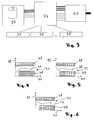
- the bolt setting device 1 comprises a magazine 3 for fastening elements, in particular bolts, of which a stock is contained in the magazine 3.
- the bolt setting tool 1 further comprises a handle 4, which can be grasped by the user's hand.
- a safety device 6 is attached, which comprises a pressure bar 8.
- the pressing rod 8 is made of its in FIG. 1 illustrated rest position in a in FIG. 2 shown working position moves. If the Anpressstange 8 has taken its working position, then, as in FIG. 2 indicated by dashed lines, a pin 9 are positioned from the magazine 3 in a drive-in channel of the bolt setting device 1.
- the bolt setting device 1 comprises a buffer 10 for buffering drive energy, which can be delivered abruptly in a bolt setting operation to set a bolt.
- the buffer 10 comprises a spring 11, which in FIG. 1 in a relaxed and in FIG. 2 is shown in a tensioned state.
- the spring 11 is designed as a helical compression spring and bears with one end against a stop 12.
- the stop 12 is translationally guided back and forth on a guide 14.
- the stop 12 is coupled to a threaded spindle 15 which is rotatably guided in a spindle nut 16.
- the spindle nut 16 is rotatably mounted in the housing 2 and driven by a drive motor 20 via a belt drive 18.
- the threaded spindle 15 is guided in the housing 2 in such a way that, with a corresponding drive by the drive motor 20, it moves out of its in FIG. 1 illustrated rest position in their in FIG. 2 shown working position moves.
- the threaded spindle 15 has a detent 23 on its end facing away from the coupling element 13.
- the latch 23 is in FIG. 1 arranged in the vicinity of the belt drive 18.
- FIG. 2 is the threaded spindle 15 so far shifted away from the bolt setting end 5, that the detent latches with a pawl 21 of a locking device 22, so that the threaded spindle 15 in their in FIG. 2 shown working position is held in which the spring 11 is clamped between the stop 12 and the spindle nut 16.
- the bolt setting device 1 comprises in the handle 4 an electronic control 24, an accumulator 25 and a trigger or trigger 26 with which the bolt setting device 1 is actuated.
- FIG. 3 are interfaces for controlling the bolt-firing device 1 from the Figures 1 and 2 shown greatly simplified.
- the controller 24 of the bolt-firing device 1 is indicated by a central square.
- the controller 24 is connected via control lines, signal lines and / or supply lines to the accumulator 25 in connection.
- the controller 24 is connected via control lines, signal lines and / or supply lines to the electric drive motor 20 in connection.
- the controller 24 is further connected via control lines or signal lines or supply lines with switching and / or sensor devices 31, 32, 33.
- the switching and / or sensor devices 31 to 33 enable monitoring functions, which in the following, with reference to FIG. 9 , described in detail.
- FIGS. 4 to 6 are three Cartesian coordinate diagrams, each with an x-axis 41 and a y-axis 42 shown.
- FIG. 4 is the speed of the drive motor 20 of the bolt-firing device 1 in the form of a speed curve 44 applied over a clamping stroke of the spring 11.
- FIG. 5 the electrical voltage of the drive motor 20 is applied in the form of a voltage curve 45 over the clamping stroke.
- FIG. 6 is the electric current of the drive motor 20 in the form of a current waveform 46 over the clamping stroke applied.
- By hatched rectangles 48 and 49 are in the FIGS. 4 to 6 poor operating ranges of the drive motor 20 indicated.
- a good region 50 is arranged, in which the characteristic curve 44; 45; 46 runs.
- the courses 44 to 46 are detected with the aid of the switching and / or sensor devices 31 to 33 and analyzed and monitored in the controller 24. As soon as one of the courses 44 to 46 leaves the good area 50 during operation of the bolt setting device 1, this is detected in the controller 24. Also from the states of the sensor devices 31 to 33, plausibility checks can identify problems in the device.
- a display 51 and an interface 52 may have.
- the display 51 is used to pass on information from the controller 24 to the user or user of the bolt gun.
- an optical signal of the display 51 the user can be informed, for example, that a signal of the courses 44 to 46 lies in one of the bad areas 48, 49. Then, the user can turn off the bolt setting device 1, for example, to avoid damaging it. It is also possible to pass on acoustic signals to the user.
- the interface is used to program the controller.
- the interface is used to expand the control. This makes it possible to integrate an additional control module, which transmits, for example, the recorded operating data (via suitable methods such as GSM) directly and promptly to the owner and / or the manufacturer.
- the device has a display for illuminating the environment (lighting), which allows a use of equipment even in poor lighting conditions.
- the user is informed about the display, in case of failure, for example, by flashing.
- FIG. 8 is indicated that with the aid of a connecting line 54, a computer 55 can be connected to the interface 52 to the bolt setting device 1.
- the connection can also be wireless.
- a service person with the Computer 55 read information from the controller 24 of the bolt gun 1. This makes it possible to deduce the state of the bolt gun without disassembly.
- the bolt gun 1 may have different monitoring functions.
- the overall apparatus operation of the bolt gun 1 can be secured by implementing various operations.
- the bolt setting device 1 comprises a bolt guide monitoring 61, a front buffer memory 62, a rear buffer memory 63, a locking device monitoring 64, a battery monitoring 65, a trigger monitoring 66 and a Anpressüberwachung 68.
- the bolt guide monitoring 61 is monitored, for example, whether a bolt has been removed, whether a bolt is in the bolt guide, whether the bolt guide is locked or unlocked.
- the front buffer memory monitoring 62 is monitored, for example, whether the spring 11 is relaxed, whether the stopper 12, which is also referred to as a piston, the front, that is in the vicinity of the bolt setting end 5 and / or if the clutch is closed .
- the rear buffer memory monitoring 63 is monitored, for example, where the threaded spindle 15 is located, or which position the spindle nut 16 occupies.
- the lock device monitor 64 monitors whether the latch 21 of the lock device 22 is open or closed.
- the battery monitor 65 for example, the current and the voltage of the battery 25 are monitored.
- the trigger monitor 66 monitors, for example, whether the trigger 26 is pressed lightly, completely or not at all.
- the following rechargeable batteries can be used in particular as the rechargeable battery 25: Lilon, LiPol, Li-metal, Zn-Air.
- Li means lithium.
- BL means brushless or brushless, DC direct current or DC, AC alternating current or AC.
- the cached energy in the spring 11 is released by releasing the pawl 21 of the locking device 22.
- the pawl 21 may only be opened when the bolt gun is pressed against a workpiece to be fastened for a setting operation. With the help of the Anpressüberwachung 68 is monitored whether the bolt gun 1 is pressed against the workpiece to be fastened.
- a mechanical and / or electronic locking can be provided which ensures that the bolt setting device 1 is pressed against the workpiece or the ground.
- an expansion stage prevents unauthorized opening of the pawl 21 of the locking device 22 in that the pawl 21 can only be actuated when the bolt gun 1 is pressed not only to the ground or the workpiece, but is also in the tensioned state. This can be detected, for example, with the buffer monitoring 62, 63.
- the pawl 21 of the locking device 22 is monitored or controlled with the locking device monitoring 64.
- the stored energy can be removed in such a way that the extracted energy is used to charge the battery.
- the mechanical and / or electronic Anpressverriegelung ensures that the bolt gun 1 can only be pressed against the ground when a bolt 9 is present.
- the electronic control 24 ensures after each bolt setting that, for example, by lifting the bolt gun 1 again a new pin 9 is positioned in the bolt setting end 5.
- the electronic control 24 with the monitoring and / or diagnostic device comprises by means of the previously described switching and / or Sensor means 31 to 33, for example, the position of the bolt guide, the position of the trigger 21, the position of the trigger 26, the position of the threaded spindle 15, the position of the pressing rod 8, the position of a piston, a roller holder or a belt.
- An identification of the battery is also possible via the communication interface, which ensures that only a suitable battery for the device can be used. It is also possible to read parameters from the battery which specify the conditions of use for the device, and thus different types of batteries can be used and the device can react accordingly.
- the device state can be deduced.
- the electronic control 24 can then be prevented that the bolt gun is used, even though significant signs of wear or defects are present.
- the temperature of the electronic controller 24 and / or the temperature of the drive motor 20 and possibly also the temperature of other components can be detected in order to infer critical device conditions. As a result, unwanted damage, for example by overloading, can be prevented.
- certain operating conditions can also be limited in time. For example, it may only take a few seconds for the bolt setting to take place after the bolt gun 1 has been pressed on. If no bolt is set during this time, then the bolt gun is automatically relaxed. As a result, the user can be protected in a jammed bolt guide.
- the bolt setting device After a set of bolts, the bolt setting device only remains in operation for a certain time, for example one minute, and is subsequently switched on via the electronic control 24 automatically shut off. Then the bolt gun has to be switched on again by a touch of the hand. As a result, an undesired bridging by masking the trigger 26 can be prevented.
- the touch with the hand can be detected with a suitable sensor and / or switching device.
- the trigger 26 is monitored by the trigger monitor 66. According to one embodiment, re-pressing the device against the ground is used for reactivation.
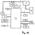
- FIG. 10 a possible control structure of the bolt gun 1 is shown in simplified form.
- the controller 24 is indicated.
- the switching and / or sensor devices 31 to 33 supply information or signals to the controller 24, as indicated by arrows.
- a main switch 70 of the bolt-firing device 1 is connected to the controller 24.
- the controller 24 communicates with the battery 25.
- a latch 71 is indicated.
- the main switch detects a hold by the user, and the controller responds to a release of the switch by removing the stored energy.
- security is increased in case of unexpected errors such as dropping the bolt gun.
- a voltage measurement and a current measurement are indicated.
- a shutdown is indicated.
- a B6 bridge 75 is indicated. It is a 6-pulse bridge circuit with semiconductor elements for controlling the electric drive motor 20. This is preferably driven by driver blocks which in turn are preferably controlled by a controller. Such integrated driver components have, in addition to the appropriate driving the bridge sacrifices still the advantage that they bring the switching elements of the B6 bridge in a defined state when undervoltage occurs.
- a temperature sensor is indicated, which communicates with the shutdown 74 and the controller 24.
- the controller 24 outputs information to the display 51.
- Further double arrows indicate that the controller 24 communicates with the interface 52 and with another service interface 77.
- another switching element is used in series, which separates by operating data such as overcurrent and / or excess temperature by the shutdown 74 the power flow from the battery to the consumers.
- memories such as capacitors makes sense.
- these memory are preferably placed between the other switching element and the B6 bridge and after the battery supply via suitable wiring of the other switching element controlled supplies with charge.
- a fan and a parking brake are indicated, which are controlled by the controller 24.
- the fan 78 serves to circulate components in the bolt setting device 1 for cooling with cooling air.
- the parking brake 79 serves to slow down movements when relaxing the buffer 10 and / or to keep the buffer in the tensioned or charged state.
- the parking brake 79 may cooperate for this purpose, for example with the belt drive 18.
Landscapes
- Engineering & Computer Science (AREA)
- Mechanical Engineering (AREA)
- Portable Nailing Machines And Staplers (AREA)
- Details Of Spanners, Wrenches, And Screw Drivers And Accessories (AREA)
- Safety Devices In Control Systems (AREA)
Applications Claiming Priority (1)
| Application Number | Priority Date | Filing Date | Title |
|---|---|---|---|
| DE102010030055A DE102010030055A1 (de) | 2010-06-15 | 2010-06-15 | Elektrisch betreibbares Bolzensetzgerät und Verfahren zum Betreiben des Bolzensetzgerätes |
Publications (3)
| Publication Number | Publication Date |
|---|---|
| EP2397260A2 true EP2397260A2 (fr) | 2011-12-21 |
| EP2397260A3 EP2397260A3 (fr) | 2015-04-01 |
| EP2397260B1 EP2397260B1 (fr) | 2017-12-13 |
Family
ID=44484824
Family Applications (1)
| Application Number | Title | Priority Date | Filing Date |
|---|---|---|---|
| EP11166651.7A Active EP2397260B1 (fr) | 2010-06-15 | 2011-05-19 | Procédé de fonctionnement d'un appareil de fixation de boulons |
Country Status (8)
| Country | Link |
|---|---|
| US (1) | US20110303428A1 (fr) |
| EP (1) | EP2397260B1 (fr) |
| JP (1) | JP5723686B2 (fr) |
| KR (1) | KR101898287B1 (fr) |
| CN (1) | CN102284934B (fr) |
| AU (1) | AU2011202764B2 (fr) |
| DE (1) | DE102010030055A1 (fr) |
| TW (1) | TWI562866B (fr) |
Cited By (4)
| Publication number | Priority date | Publication date | Assignee | Title |
|---|---|---|---|---|
| WO2014026966A3 (fr) * | 2012-08-17 | 2014-07-10 | Hilti Aktiengesellschaft | Appareil d'enfoncement avec blocage de sécurité |
| EP3670090A1 (fr) * | 2018-12-18 | 2020-06-24 | Hilti Aktiengesellschaft | Dispositif, appareil d'entraînement et procédé |
| EP3653342A3 (fr) * | 2018-10-26 | 2020-12-09 | Max Co., Ltd. | Outil électrique |
| WO2021119702A1 (fr) * | 2019-12-18 | 2021-06-24 | Rohrmoser Florian | Outil à commande électromécanique pour entraîner des éléments de fixation |
Families Citing this family (33)
| Publication number | Priority date | Publication date | Assignee | Title |
|---|---|---|---|---|
| DE102010030098A1 (de) * | 2010-06-15 | 2011-12-15 | Hilti Aktiengesellschaft | Eintreibvorrichtung |
| DE102010030065A1 (de) | 2010-06-15 | 2011-12-15 | Hilti Aktiengesellschaft | Eintreibvorrichtung |
| EP2397272B1 (fr) * | 2010-06-15 | 2018-09-12 | HILTI Aktiengesellschaft | Dispositif d'enfoncement |
| DE102010030118A1 (de) | 2010-06-15 | 2011-12-15 | Hilti Aktiengesellschaft | Eintreibvorrichtung |
| DE102011077442B4 (de) * | 2011-06-14 | 2025-06-26 | Robert Bosch Gmbh | Getriebelose Handwerkzeugmaschine |
| CN102645331B (zh) * | 2012-04-28 | 2014-09-24 | 昆山长运电子工业有限公司 | 把手销钉检测治具 |
| US20140263535A1 (en) * | 2013-03-12 | 2014-09-18 | Techtronic Power Tools Technology Limited | Direct current fastening device and related control methods |
| EP2801449A1 (fr) * | 2013-05-06 | 2014-11-12 | HILTI Aktiengesellschaft | Dispositif d'entraînement et procédé d'utilisation d'un dispositif d'enfoncement |
| JP6123552B2 (ja) * | 2013-07-31 | 2017-05-10 | 日立工機株式会社 | 留め具打込機 |
| DE102014206076A1 (de) * | 2014-03-31 | 2015-10-01 | Robert Bosch Gmbh | Handwerkzeugmaschine, Verfahren zum Betreiben |
| DE102014226162A1 (de) * | 2014-12-17 | 2016-06-23 | Robert Bosch Gmbh | Werkzeug und verfahren zur behandlung eines werkstücks mit einemwerkzeugelement eines werkzeugs |
| JP6881576B2 (ja) * | 2017-05-31 | 2021-06-02 | 工機ホールディングス株式会社 | 打込機 |
| US11571792B2 (en) * | 2017-07-31 | 2023-02-07 | Koki Holdings Co., Ltd. | Driver |
| CN107598844B (zh) * | 2017-09-29 | 2023-08-11 | 王家宏 | 电动射钉枪 |
| EP3513912A1 (fr) * | 2018-01-22 | 2019-07-24 | Von Arx AG | Appareil de pressage à commande manuelle |
| CN110170967B (zh) * | 2018-02-20 | 2023-03-21 | 美克司株式会社 | 打入工具 |
| JP7259338B2 (ja) * | 2018-02-20 | 2023-04-18 | マックス株式会社 | 打ち込み工具 |
| US11034006B2 (en) | 2019-01-25 | 2021-06-15 | Robert Bosch Tool Corporation | Pneumatic linear fastener driving tool |
| US11130221B2 (en) | 2019-01-31 | 2021-09-28 | Milwaukee Electric Tool Corporation | Powered fastener driver |
| US12186868B2 (en) | 2019-11-01 | 2025-01-07 | Koki Holdings Co., Ltd. | Driving device |
| CN111469097A (zh) * | 2020-04-16 | 2020-07-31 | 周小威 | 排钉锤 |
| JP7459648B2 (ja) * | 2020-05-14 | 2024-04-02 | マックス株式会社 | 打ち込み工具 |
| JP7752824B2 (ja) * | 2021-05-10 | 2025-10-14 | マックス株式会社 | 打込工具 |
| JP7836507B2 (ja) * | 2021-06-04 | 2026-03-27 | マックス株式会社 | 電動工具 |
| WO2023158729A1 (fr) | 2022-02-18 | 2023-08-24 | Milwaukee Electric Tool Corporation | Visseuse de fermeture motorisée |
| US12434371B2 (en) | 2022-03-23 | 2025-10-07 | Milwaukee Electric Tool Corporation | Electronic clutch for power tools |
| US12122028B2 (en) | 2022-05-26 | 2024-10-22 | Milwaukee Electric Tool Corporation | Electronic clutch for powered fastener driver |
| TWI893314B (zh) * | 2022-06-24 | 2025-08-11 | 鑽全實業股份有限公司 | 電動驅動工具及其電池衰退偵測方法 |
| US12257681B2 (en) * | 2022-09-15 | 2025-03-25 | Taizhou Dajiang Ind. Co. Ltd. | Energy storage and striking mechanisms and nail guns having same |
| CN115828164A (zh) * | 2022-12-29 | 2023-03-21 | 浙江工业大学台州研究院 | 一种基于数据驱动的电动钉枪故障类型识别方法 |
| US12318899B2 (en) | 2023-01-27 | 2025-06-03 | Milwaukee Electric Tool Corporation | Powered fastener driver |
| US12479075B2 (en) | 2023-01-27 | 2025-11-25 | Milwaukee Electric Tool Corporation | Powered fastener driver |
| DE102024112566A1 (de) | 2023-05-05 | 2024-11-07 | Milwaukee Electric Tool Corporation | Fremdkraftbetätigter befestigungsmitteleintreiber |
Citations (2)
| Publication number | Priority date | Publication date | Assignee | Title |
|---|---|---|---|---|
| WO2007142997A2 (fr) | 2006-05-31 | 2007-12-13 | Stanley Fastening Systems, L.P. | Moyen d'entraînement d'éléments de fixation |
| DE102006000517A1 (de) | 2006-12-12 | 2008-06-19 | Hilti Ag | Handgeführtes Eintreibgerät |
Family Cites Families (28)
| Publication number | Priority date | Publication date | Assignee | Title |
|---|---|---|---|---|
| JPH0557633A (ja) * | 1991-08-27 | 1993-03-09 | Matsushita Electric Works Ltd | 打ち込み工具 |
| JP2568736Y2 (ja) * | 1993-12-06 | 1998-04-15 | マックス株式会社 | 可搬形電動ステープル打機 |
| JPH08197455A (ja) * | 1995-01-06 | 1996-08-06 | Sencorp | はずみ車駆動の電動機器 |
| DE10033362A1 (de) * | 2000-07-08 | 2002-01-17 | Hilti Ag | Elektrohandwerkzeug mit Leerschlagabschaltung |
| US6604666B1 (en) * | 2001-08-20 | 2003-08-12 | Tricord Solutions, Inc. | Portable electrical motor driven nail gun |
| SE523684C2 (sv) * | 2001-10-04 | 2004-05-11 | Isaberg Rapid Ab | Styranordning för en drivmotor i en häftapparat |
| JP2004148416A (ja) * | 2002-10-28 | 2004-05-27 | Matsushita Electric Works Ltd | 電動釘打機 |
| DE10303006B4 (de) * | 2003-01-27 | 2019-01-03 | Hilti Aktiengesellschaft | Handgeführtes Arbeitsgerät |
| DE10332242A1 (de) * | 2003-07-16 | 2005-02-03 | Andreas Stihl Ag & Co. Kg | Handgeführtes Arbeitsgerät |
| JP3992676B2 (ja) * | 2003-11-20 | 2007-10-17 | 日東工器株式会社 | 電動ドライバ |
| EP1584418B1 (fr) * | 2004-04-02 | 2008-05-07 | BLACK & DECKER INC. | Outil de fixation avec interrupteur pour sélectioner le mode |
| US6971567B1 (en) * | 2004-10-29 | 2005-12-06 | Black & Decker Inc. | Electronic control of a cordless fastening tool |
| US8505798B2 (en) * | 2005-05-12 | 2013-08-13 | Stanley Fastening Systems, L.P. | Fastener driving device |
| JP2008068358A (ja) * | 2006-09-14 | 2008-03-27 | Hitachi Koki Co Ltd | 電動式打込機 |
| JP5011903B2 (ja) * | 2006-09-15 | 2012-08-29 | マックス株式会社 | 手持ち工具 |
| JP4939985B2 (ja) * | 2007-03-16 | 2012-05-30 | 株式会社マキタ | 打込み作業工具 |
| US7646157B2 (en) * | 2007-03-16 | 2010-01-12 | Black & Decker Inc. | Driving tool and method for controlling same |
| US20080298784A1 (en) * | 2007-06-04 | 2008-12-04 | Mark Allen Kastner | Method of Sensing Speed of Electric Motors and Generators |
| JP5001751B2 (ja) * | 2007-08-27 | 2012-08-15 | 株式会社マキタ | 打込み工具 |
| DE102007062727A1 (de) * | 2007-12-27 | 2009-07-02 | Robert Bosch Gmbh | Vorrichtung und Verfahren zum Ergreifen einer Sicherungsmaßnahme bei einem Elektrowerkzeug |
| JP5424009B2 (ja) * | 2008-01-15 | 2014-02-26 | 日立工機株式会社 | 留め具打込機 |
| JP5146734B2 (ja) * | 2008-01-15 | 2013-02-20 | 日立工機株式会社 | 留め具打込機 |
| GB0809868D0 (en) * | 2008-05-30 | 2008-07-09 | Black & Decker Inc | Fastener driving tool |
| JP5062077B2 (ja) * | 2008-07-18 | 2012-10-31 | マックス株式会社 | 空気圧式ネジ打込み機 |
| US8136606B2 (en) * | 2008-08-14 | 2012-03-20 | Robert Bosch Gmbh | Cordless nail gun |
| US8210411B2 (en) * | 2008-09-23 | 2012-07-03 | Ethicon Endo-Surgery, Inc. | Motor-driven surgical cutting instrument |
| DE102008042699A1 (de) * | 2008-10-09 | 2010-04-22 | Hilti Aktiengesellschaft | Handgeführtes Eintreibgerät |
| CN201471377U (zh) * | 2009-08-07 | 2010-05-19 | 文星毅 | 便携式智能直流电动射钉枪 |
-
2010
- 2010-06-15 DE DE102010030055A patent/DE102010030055A1/de not_active Withdrawn
-
2011
- 2011-05-18 TW TW100117369A patent/TWI562866B/zh active
- 2011-05-19 EP EP11166651.7A patent/EP2397260B1/fr active Active
- 2011-06-09 AU AU2011202764A patent/AU2011202764B2/en active Active
- 2011-06-10 US US13/157,825 patent/US20110303428A1/en not_active Abandoned
- 2011-06-13 KR KR1020110056865A patent/KR101898287B1/ko active Active
- 2011-06-14 CN CN201110158501.9A patent/CN102284934B/zh active Active
- 2011-06-14 JP JP2011131933A patent/JP5723686B2/ja active Active
Patent Citations (2)
| Publication number | Priority date | Publication date | Assignee | Title |
|---|---|---|---|---|
| WO2007142997A2 (fr) | 2006-05-31 | 2007-12-13 | Stanley Fastening Systems, L.P. | Moyen d'entraînement d'éléments de fixation |
| DE102006000517A1 (de) | 2006-12-12 | 2008-06-19 | Hilti Ag | Handgeführtes Eintreibgerät |
Cited By (11)
| Publication number | Priority date | Publication date | Assignee | Title |
|---|---|---|---|---|
| WO2014026966A3 (fr) * | 2012-08-17 | 2014-07-10 | Hilti Aktiengesellschaft | Appareil d'enfoncement avec blocage de sécurité |
| CN104703761A (zh) * | 2012-08-17 | 2015-06-10 | 喜利得股份公司 | 包括安全截止装置的驱入设备 |
| US10046448B2 (en) | 2012-08-17 | 2018-08-14 | Hilti Aktiengesellschaft | Fastener driving tool with safety lock |
| EP3653342A3 (fr) * | 2018-10-26 | 2020-12-09 | Max Co., Ltd. | Outil électrique |
| US11518012B2 (en) | 2018-10-26 | 2022-12-06 | Max Co., Ltd. | Electric tool |
| EP4309851A1 (fr) * | 2018-10-26 | 2024-01-24 | Max Co., Ltd. | Outil électrique |
| EP3670090A1 (fr) * | 2018-12-18 | 2020-06-24 | Hilti Aktiengesellschaft | Dispositif, appareil d'entraînement et procédé |
| WO2020126367A1 (fr) * | 2018-12-18 | 2020-06-25 | Hilti Aktiengesellschaft | Dispositif, appareil d'enfoncement et procédé |
| US11926029B2 (en) | 2018-12-18 | 2024-03-12 | Hilti Aktiengesellschaft | Apparatus, driving-in device and method |
| WO2021119702A1 (fr) * | 2019-12-18 | 2021-06-24 | Rohrmoser Florian | Outil à commande électromécanique pour entraîner des éléments de fixation |
| US12304045B2 (en) | 2019-12-18 | 2025-05-20 | Innovation Network Austria Dienstleistungs-Gmbh | Electrically-mechanically operated tool for driving fasteners |
Also Published As
| Publication number | Publication date |
|---|---|
| TW201206646A (en) | 2012-02-16 |
| KR20110136729A (ko) | 2011-12-21 |
| US20110303428A1 (en) | 2011-12-15 |
| JP2012000751A (ja) | 2012-01-05 |
| AU2011202764A1 (en) | 2012-01-12 |
| TWI562866B (en) | 2016-12-21 |
| EP2397260A3 (fr) | 2015-04-01 |
| KR101898287B1 (ko) | 2018-09-12 |
| AU2011202764B2 (en) | 2014-05-01 |
| DE102010030055A1 (de) | 2011-12-15 |
| CN102284934A (zh) | 2011-12-21 |
| EP2397260B1 (fr) | 2017-12-13 |
| CN102284934B (zh) | 2016-09-21 |
| JP5723686B2 (ja) | 2015-05-27 |
Similar Documents
| Publication | Publication Date | Title |
|---|---|---|
| EP2397260B1 (fr) | Procédé de fonctionnement d'un appareil de fixation de boulons | |
| DE102010056523B4 (de) | Tragbares akkubetriebenes Werkzeug mit elektrischem Pufferelement und Verfahren zum Auswechseln des Akkumulators | |
| EP2225057B1 (fr) | Procédé pour poser des éléments rivetés au moyen d'un appareil de rivetage portable entraîné par un moteur électrique, et appareil de rivetage | |
| EP2994273B1 (fr) | Dispositif d'entraînement et procédé d'utilisation d'un dispositif d'enfoncement | |
| DE102007032053A1 (de) | Vorrichtung und Verfahren zur Regulierung des Stromverbrauchs eines elektrischen Geräts | |
| DE102017123169A1 (de) | Elektrisches Kraftwerkzeug und Verfahren zum Erfassen einer Drehbewegung eines Hauptkörpers eines elektrischen Kraftwerkzeuges | |
| US9873189B2 (en) | Method for operating a hand-held working device | |
| EP2402122A2 (fr) | Machine-outil | |
| DE10262088B4 (de) | Chirurgisches Motorensystem | |
| EP3600778B1 (fr) | Procédé de fonctionnement d'un outil de fixation | |
| DE102004021536A1 (de) | Verfahren und Vorrichtung zum Herstellen von Schraubverbindungen | |
| EP3664968B1 (fr) | Dispositif d'enfoncement et son procédé d'utilisation | |
| EP2397274A2 (fr) | Appareil de fixation de boulons pouvant fonctionner de manière électrique | |
| DE102010063148A1 (de) | Verfahren und Vorrichtung zum Betreiben eines elektromotorisch angetriebenen Elektrohandwerkzeugs | |
| WO2022207169A1 (fr) | Procédé de diagnostic acoustique d'un outil de travail et système de mise en œuvre dudit procédé | |
| DE102024208746A1 (de) | Verfahren zur Fehlerdiagnose eines Bearbeitungsgeräts sowie Bearbeitungsgerät zur Durchführung des Verfahrens | |
| WO2018166553A1 (fr) | Procédé et dispositif de maintien d'une position absolue détectée d'un moteur électrique agissant en tant qu'actionneur en cas de fonctionnement critique | |
| EP2524771B1 (fr) | Appareil de fixation de boulons et procédé de fonctionnement d'un appareil de fixation de boulons | |
| EP1579957A2 (fr) | Tournevis à air comprimé | |
| WO2024110131A1 (fr) | Protection de manipulation pour un appareil portatif | |
| CN119610979A (zh) | 一种闭式气路空簧单元的驱动系统 |
Legal Events
| Date | Code | Title | Description |
|---|---|---|---|
| AK | Designated contracting states |
Kind code of ref document: A2 Designated state(s): AL AT BE BG CH CY CZ DE DK EE ES FI FR GB GR HR HU IE IS IT LI LT LU LV MC MK MT NL NO PL PT RO RS SE SI SK SM TR |
|
| AX | Request for extension of the european patent |
Extension state: BA ME |
|
| PUAI | Public reference made under article 153(3) epc to a published international application that has entered the european phase |
Free format text: ORIGINAL CODE: 0009012 |
|
| PUAL | Search report despatched |
Free format text: ORIGINAL CODE: 0009013 |
|
| AK | Designated contracting states |
Kind code of ref document: A3 Designated state(s): AL AT BE BG CH CY CZ DE DK EE ES FI FR GB GR HR HU IE IS IT LI LT LU LV MC MK MT NL NO PL PT RO RS SE SI SK SM TR |
|
| AX | Request for extension of the european patent |
Extension state: BA ME |
|
| RIC1 | Information provided on ipc code assigned before grant |
Ipc: B25C 1/06 20060101ALI20150224BHEP Ipc: B25C 1/00 20060101AFI20150224BHEP |
|
| 17P | Request for examination filed |
Effective date: 20151001 |
|
| RBV | Designated contracting states (corrected) |
Designated state(s): AL AT BE BG CH CY CZ DE DK EE ES FI FR GB GR HR HU IE IS IT LI LT LU LV MC MK MT NL NO PL PT RO RS SE SI SK SM TR |
|
| 17Q | First examination report despatched |
Effective date: 20160412 |
|
| GRAP | Despatch of communication of intention to grant a patent |
Free format text: ORIGINAL CODE: EPIDOSNIGR1 |
|
| INTG | Intention to grant announced |
Effective date: 20170914 |
|
| GRAS | Grant fee paid |
Free format text: ORIGINAL CODE: EPIDOSNIGR3 |
|
| GRAA | (expected) grant |
Free format text: ORIGINAL CODE: 0009210 |
|
| AK | Designated contracting states |
Kind code of ref document: B1 Designated state(s): AL AT BE BG CH CY CZ DE DK EE ES FI FR GB GR HR HU IE IS IT LI LT LU LV MC MK MT NL NO PL PT RO RS SE SI SK SM TR |
|
| REG | Reference to a national code |
Ref country code: GB Ref legal event code: FG4D Free format text: NOT ENGLISH |
|
| REG | Reference to a national code |
Ref country code: AT Ref legal event code: REF Ref document number: 953920 Country of ref document: AT Kind code of ref document: T Effective date: 20171215 Ref country code: CH Ref legal event code: EP |
|
| REG | Reference to a national code |
Ref country code: IE Ref legal event code: FG4D Free format text: LANGUAGE OF EP DOCUMENT: GERMAN |
|
| REG | Reference to a national code |
Ref country code: DE Ref legal event code: R096 Ref document number: 502011013433 Country of ref document: DE |
|
| REG | Reference to a national code |
Ref country code: NL Ref legal event code: MP Effective date: 20171213 |
|
| REG | Reference to a national code |
Ref country code: LT Ref legal event code: MG4D |
|
| PG25 | Lapsed in a contracting state [announced via postgrant information from national office to epo] |
Ref country code: FI Free format text: LAPSE BECAUSE OF FAILURE TO SUBMIT A TRANSLATION OF THE DESCRIPTION OR TO PAY THE FEE WITHIN THE PRESCRIBED TIME-LIMIT Effective date: 20171213 Ref country code: SE Free format text: LAPSE BECAUSE OF FAILURE TO SUBMIT A TRANSLATION OF THE DESCRIPTION OR TO PAY THE FEE WITHIN THE PRESCRIBED TIME-LIMIT Effective date: 20171213 Ref country code: NO Free format text: LAPSE BECAUSE OF FAILURE TO SUBMIT A TRANSLATION OF THE DESCRIPTION OR TO PAY THE FEE WITHIN THE PRESCRIBED TIME-LIMIT Effective date: 20180313 Ref country code: LT Free format text: LAPSE BECAUSE OF FAILURE TO SUBMIT A TRANSLATION OF THE DESCRIPTION OR TO PAY THE FEE WITHIN THE PRESCRIBED TIME-LIMIT Effective date: 20171213 |
|
| REG | Reference to a national code |
Ref country code: FR Ref legal event code: PLFP Year of fee payment: 8 |
|
| PG25 | Lapsed in a contracting state [announced via postgrant information from national office to epo] |
Ref country code: HR Free format text: LAPSE BECAUSE OF FAILURE TO SUBMIT A TRANSLATION OF THE DESCRIPTION OR TO PAY THE FEE WITHIN THE PRESCRIBED TIME-LIMIT Effective date: 20171213 Ref country code: GR Free format text: LAPSE BECAUSE OF FAILURE TO SUBMIT A TRANSLATION OF THE DESCRIPTION OR TO PAY THE FEE WITHIN THE PRESCRIBED TIME-LIMIT Effective date: 20180314 Ref country code: RS Free format text: LAPSE BECAUSE OF FAILURE TO SUBMIT A TRANSLATION OF THE DESCRIPTION OR TO PAY THE FEE WITHIN THE PRESCRIBED TIME-LIMIT Effective date: 20171213 Ref country code: LV Free format text: LAPSE BECAUSE OF FAILURE TO SUBMIT A TRANSLATION OF THE DESCRIPTION OR TO PAY THE FEE WITHIN THE PRESCRIBED TIME-LIMIT Effective date: 20171213 Ref country code: BG Free format text: LAPSE BECAUSE OF FAILURE TO SUBMIT A TRANSLATION OF THE DESCRIPTION OR TO PAY THE FEE WITHIN THE PRESCRIBED TIME-LIMIT Effective date: 20180313 |
|
| PG25 | Lapsed in a contracting state [announced via postgrant information from national office to epo] |
Ref country code: NL Free format text: LAPSE BECAUSE OF FAILURE TO SUBMIT A TRANSLATION OF THE DESCRIPTION OR TO PAY THE FEE WITHIN THE PRESCRIBED TIME-LIMIT Effective date: 20171213 |
|
| PG25 | Lapsed in a contracting state [announced via postgrant information from national office to epo] |
Ref country code: CZ Free format text: LAPSE BECAUSE OF FAILURE TO SUBMIT A TRANSLATION OF THE DESCRIPTION OR TO PAY THE FEE WITHIN THE PRESCRIBED TIME-LIMIT Effective date: 20171213 Ref country code: ES Free format text: LAPSE BECAUSE OF FAILURE TO SUBMIT A TRANSLATION OF THE DESCRIPTION OR TO PAY THE FEE WITHIN THE PRESCRIBED TIME-LIMIT Effective date: 20171213 Ref country code: EE Free format text: LAPSE BECAUSE OF FAILURE TO SUBMIT A TRANSLATION OF THE DESCRIPTION OR TO PAY THE FEE WITHIN THE PRESCRIBED TIME-LIMIT Effective date: 20171213 Ref country code: CY Free format text: LAPSE BECAUSE OF FAILURE TO SUBMIT A TRANSLATION OF THE DESCRIPTION OR TO PAY THE FEE WITHIN THE PRESCRIBED TIME-LIMIT Effective date: 20171213 Ref country code: SK Free format text: LAPSE BECAUSE OF FAILURE TO SUBMIT A TRANSLATION OF THE DESCRIPTION OR TO PAY THE FEE WITHIN THE PRESCRIBED TIME-LIMIT Effective date: 20171213 |
|
| PG25 | Lapsed in a contracting state [announced via postgrant information from national office to epo] |
Ref country code: RO Free format text: LAPSE BECAUSE OF FAILURE TO SUBMIT A TRANSLATION OF THE DESCRIPTION OR TO PAY THE FEE WITHIN THE PRESCRIBED TIME-LIMIT Effective date: 20171213 Ref country code: IS Free format text: LAPSE BECAUSE OF FAILURE TO SUBMIT A TRANSLATION OF THE DESCRIPTION OR TO PAY THE FEE WITHIN THE PRESCRIBED TIME-LIMIT Effective date: 20180413 Ref country code: PL Free format text: LAPSE BECAUSE OF FAILURE TO SUBMIT A TRANSLATION OF THE DESCRIPTION OR TO PAY THE FEE WITHIN THE PRESCRIBED TIME-LIMIT Effective date: 20171213 Ref country code: SM Free format text: LAPSE BECAUSE OF FAILURE TO SUBMIT A TRANSLATION OF THE DESCRIPTION OR TO PAY THE FEE WITHIN THE PRESCRIBED TIME-LIMIT Effective date: 20171213 Ref country code: IT Free format text: LAPSE BECAUSE OF FAILURE TO SUBMIT A TRANSLATION OF THE DESCRIPTION OR TO PAY THE FEE WITHIN THE PRESCRIBED TIME-LIMIT Effective date: 20171213 |
|
| REG | Reference to a national code |
Ref country code: DE Ref legal event code: R097 Ref document number: 502011013433 Country of ref document: DE |
|
| PG25 | Lapsed in a contracting state [announced via postgrant information from national office to epo] |
Ref country code: MT Free format text: LAPSE BECAUSE OF FAILURE TO SUBMIT A TRANSLATION OF THE DESCRIPTION OR TO PAY THE FEE WITHIN THE PRESCRIBED TIME-LIMIT Effective date: 20171213 |
|
| PLBE | No opposition filed within time limit |
Free format text: ORIGINAL CODE: 0009261 |
|
| STAA | Information on the status of an ep patent application or granted ep patent |
Free format text: STATUS: NO OPPOSITION FILED WITHIN TIME LIMIT |
|
| 26N | No opposition filed |
Effective date: 20180914 |
|
| PG25 | Lapsed in a contracting state [announced via postgrant information from national office to epo] |
Ref country code: DK Free format text: LAPSE BECAUSE OF FAILURE TO SUBMIT A TRANSLATION OF THE DESCRIPTION OR TO PAY THE FEE WITHIN THE PRESCRIBED TIME-LIMIT Effective date: 20171213 |
|
| REG | Reference to a national code |
Ref country code: CH Ref legal event code: PL |
|
| REG | Reference to a national code |
Ref country code: BE Ref legal event code: MM Effective date: 20180531 |
|
| PG25 | Lapsed in a contracting state [announced via postgrant information from national office to epo] |
Ref country code: MC Free format text: LAPSE BECAUSE OF FAILURE TO SUBMIT A TRANSLATION OF THE DESCRIPTION OR TO PAY THE FEE WITHIN THE PRESCRIBED TIME-LIMIT Effective date: 20171213 |
|
| REG | Reference to a national code |
Ref country code: IE Ref legal event code: MM4A |
|
| PG25 | Lapsed in a contracting state [announced via postgrant information from national office to epo] |
Ref country code: LI Free format text: LAPSE BECAUSE OF NON-PAYMENT OF DUE FEES Effective date: 20180531 Ref country code: SI Free format text: LAPSE BECAUSE OF FAILURE TO SUBMIT A TRANSLATION OF THE DESCRIPTION OR TO PAY THE FEE WITHIN THE PRESCRIBED TIME-LIMIT Effective date: 20171213 Ref country code: CH Free format text: LAPSE BECAUSE OF NON-PAYMENT OF DUE FEES Effective date: 20180531 |
|
| PG25 | Lapsed in a contracting state [announced via postgrant information from national office to epo] |
Ref country code: LU Free format text: LAPSE BECAUSE OF NON-PAYMENT OF DUE FEES Effective date: 20180519 |
|
| PG25 | Lapsed in a contracting state [announced via postgrant information from national office to epo] |
Ref country code: IE Free format text: LAPSE BECAUSE OF NON-PAYMENT OF DUE FEES Effective date: 20180519 |
|
| PG25 | Lapsed in a contracting state [announced via postgrant information from national office to epo] |
Ref country code: BE Free format text: LAPSE BECAUSE OF NON-PAYMENT OF DUE FEES Effective date: 20180531 |
|
| REG | Reference to a national code |
Ref country code: AT Ref legal event code: MM01 Ref document number: 953920 Country of ref document: AT Kind code of ref document: T Effective date: 20180519 |
|
| PG25 | Lapsed in a contracting state [announced via postgrant information from national office to epo] |
Ref country code: AT Free format text: LAPSE BECAUSE OF NON-PAYMENT OF DUE FEES Effective date: 20180519 |
|
| PG25 | Lapsed in a contracting state [announced via postgrant information from national office to epo] |
Ref country code: TR Free format text: LAPSE BECAUSE OF FAILURE TO SUBMIT A TRANSLATION OF THE DESCRIPTION OR TO PAY THE FEE WITHIN THE PRESCRIBED TIME-LIMIT Effective date: 20171213 |
|
| PG25 | Lapsed in a contracting state [announced via postgrant information from national office to epo] |
Ref country code: PT Free format text: LAPSE BECAUSE OF FAILURE TO SUBMIT A TRANSLATION OF THE DESCRIPTION OR TO PAY THE FEE WITHIN THE PRESCRIBED TIME-LIMIT Effective date: 20171213 Ref country code: HU Free format text: LAPSE BECAUSE OF FAILURE TO SUBMIT A TRANSLATION OF THE DESCRIPTION OR TO PAY THE FEE WITHIN THE PRESCRIBED TIME-LIMIT; INVALID AB INITIO Effective date: 20110519 |
|
| PG25 | Lapsed in a contracting state [announced via postgrant information from national office to epo] |
Ref country code: MK Free format text: LAPSE BECAUSE OF NON-PAYMENT OF DUE FEES Effective date: 20171213 |
|
| PG25 | Lapsed in a contracting state [announced via postgrant information from national office to epo] |
Ref country code: AL Free format text: LAPSE BECAUSE OF FAILURE TO SUBMIT A TRANSLATION OF THE DESCRIPTION OR TO PAY THE FEE WITHIN THE PRESCRIBED TIME-LIMIT Effective date: 20171213 |
|
| PGFP | Annual fee paid to national office [announced via postgrant information from national office to epo] |
Ref country code: DE Payment date: 20250521 Year of fee payment: 15 |
|
| PGFP | Annual fee paid to national office [announced via postgrant information from national office to epo] |
Ref country code: GB Payment date: 20250521 Year of fee payment: 15 |
|
| PGFP | Annual fee paid to national office [announced via postgrant information from national office to epo] |
Ref country code: FR Payment date: 20250528 Year of fee payment: 15 |