EP1579957A2 - Tournevis à air comprimé - Google Patents
Tournevis à air comprimé Download PDFInfo
- Publication number
- EP1579957A2 EP1579957A2 EP05002097A EP05002097A EP1579957A2 EP 1579957 A2 EP1579957 A2 EP 1579957A2 EP 05002097 A EP05002097 A EP 05002097A EP 05002097 A EP05002097 A EP 05002097A EP 1579957 A2 EP1579957 A2 EP 1579957A2
- Authority
- EP
- European Patent Office
- Prior art keywords
- screwdriver
- control line
- pneumatic
- compressed air
- valve
- Prior art date
- Legal status (The legal status is an assumption and is not a legal conclusion. Google has not performed a legal analysis and makes no representation as to the accuracy of the status listed.)
- Withdrawn
Links
Images

Classifications
-
- B—PERFORMING OPERATIONS; TRANSPORTING
- B25—HAND TOOLS; PORTABLE POWER-DRIVEN TOOLS; MANIPULATORS
- B25B—TOOLS OR BENCH DEVICES NOT OTHERWISE PROVIDED FOR, FOR FASTENING, CONNECTING, DISENGAGING, OR HOLDING
- B25B23/00—Details of, or accessories for, spanners, wrenches, screwdrivers
- B25B23/14—Arrangement of torque limiters or torque indicators in wrenches or screwdrivers
- B25B23/145—Arrangement of torque limiters or torque indicators in wrenches or screwdrivers specially adapted for fluid operated wrenches or screwdrivers
- B25B23/1456—Arrangement of torque limiters or torque indicators in wrenches or screwdrivers specially adapted for fluid operated wrenches or screwdrivers having electrical components
-
- B—PERFORMING OPERATIONS; TRANSPORTING
- B25—HAND TOOLS; PORTABLE POWER-DRIVEN TOOLS; MANIPULATORS
- B25B—TOOLS OR BENCH DEVICES NOT OTHERWISE PROVIDED FOR, FOR FASTENING, CONNECTING, DISENGAGING, OR HOLDING
- B25B21/00—Portable power-driven screw or nut setting or loosening tools; Attachments for drilling apparatus serving the same purpose
-
- B—PERFORMING OPERATIONS; TRANSPORTING
- B25—HAND TOOLS; PORTABLE POWER-DRIVEN TOOLS; MANIPULATORS
- B25B—TOOLS OR BENCH DEVICES NOT OTHERWISE PROVIDED FOR, FOR FASTENING, CONNECTING, DISENGAGING, OR HOLDING
- B25B23/00—Details of, or accessories for, spanners, wrenches, screwdrivers
- B25B23/14—Arrangement of torque limiters or torque indicators in wrenches or screwdrivers
- B25B23/145—Arrangement of torque limiters or torque indicators in wrenches or screwdrivers specially adapted for fluid operated wrenches or screwdrivers
Definitions
- the invention relates to a pneumatic wrench device with a pneumatically operated Hand screwdriver, a compressed air motor, a compressed air connection and a control line.
- a monitored pneumatic screwdriver in which an arranged in the compressed air supply external valve for the compressed air supply is switched by a control device.
- the control device is at the same time via a line with a sensor integrated in the pneumatic screwdriver connected, which detects the operation of a switch lever.
- the control device it is monitored whether a proper screwing is done. Detected the control device a Fehlverschraubung, so is via a display device an optical or audible signal is emitted to the operator to draw attention to the malfunction.
- the individual components control device, external valve, external indicator and pneumatic screwdriver are located in close proximity to the workplace so that the operator Has access to the individual components.
- a pneumatic wrench device with an air-powered hand-held screwdriver that has a compressed-air motor, has a compressed air connection for a compressed air supply and a control line.
- a check valve for the compressed air supply is integrated, which can be controlled externally via the control line.
- the hand screwdriver In the hand screwdriver are the components mentioned above, in particular the electrically controllable shut-off valve, the at least one electrical sensor for Determination of switching on and off, as well as the torque sensor integrated and connected to the control line.
- the control device is expediently an electric power tool on the handheld screwdriver Contact plug provided.
- the hand screwdriver needs at work, therefore, only one at work available connected compressed air connection and a connection for the control line connected be ready for use immediately.
- the electrical remote monitoring and remote control of these three components are in the controller preferably all operating conditions and functions of the hand screwdriver monitored and in case of malfunction, the hand screwdriver is locked. From the signals transmitted to the control device can namely namely in particular the number of screw connections per workpiece, the torque curve per fitting and determine the length of time per fitting and check whether these values are within specified target ranges.
- FIG. 1 The sectional view of FIG. 1 is based on a construction or workshop drawing, in which the individual components of a hand screwdriver 2 are drawn in a manner conventional and understandable to the person skilled in the art. Therefore, in the following, only the individual functional blocks of the glove will be described 2 explained in more detail.
- the structure of the individual function blocks per se is known or readily executed by the skilled person.
- the hand screwdriver 2 has a housing 4, which at its rear End of a compressed air connection 6 and an electrical connection 8 for a here shown in detail, in particular multi-core external control line 10 has.
- the individual wires of the external control line 10 are of the electrical Terminal 8 from here over for clarity not shown internal in the interior of the housing 4 extending control lines with different Components for their control, ie monitoring or control, connected, as will be explained in more detail below.
- a screw cap 12 is arranged, about the screwdriver 2 screws screwed into a workpiece become.
- the front end 2 of the elongated handgrip are one towards the rear end mechanical torque coupling 14, a torque sensor 16, a pneumatic motor 18, a via a valve pin 20 mechanically actuated start / stop valve 22, a sensor 24 for the valve 22 and a check valve 26 are arranged.
- Farther is on the outside of the housing 4, an optical display element 28 with Light emitting diodes provided.
- the torque sensor 16, the sensor 24, the check valve 26 and the display element 28 are each initially via an internal control line with the electrical connection 8 and then proceeding via the external control line 10 is connected to a control device 30 (see Fig. 2).
- the torque sensor 16 is an electric torque sensor, for example a so-called DMS (strain-measuring strip) torque sensor used.
- the sensor 24 is designed and detected, for example, as a proximity switch the position of a closure element 32 in the embodiment as a ball valve trained valve 22.
- the closure element 32 is in this case over the Valve pin 20 is actuated, in mechanical operative connection with the screw attachment 12 stands. By placing the spring-loaded screw attachment 12 and Pressing against the screw with a predetermined pressure, the valve pin 20 within the hand screw 2 pushed back so that the Valve 22 opens.
- the check valve 26 is in particular a conventional, electrical controllable pneumatic valve, which is designed such that it when activated to a forced interruption of a compressed air supply 34th leads to the compressed air motor 18.
- an adjustment lever 36 is provided, via which the direction of rotation of the screw attachment 12 can be adjusted.
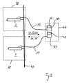
- Such a hand screwdriver 2 becomes, for example, within a production line provided at a workplace 38.
- Fig. 2 are here For example, several hand screwdriver 2 at several workstations 38 via a common compressed air line 40 connected to a compressed air supply.
- the hand screwdrivers 2 are each of their associated control device 30 are controlled and connected to it via the external control line 10.
- the control devices 30 can in this case in a common unit 44 may be integrated, as indicated by the dashed lines. How out This schematic illustration shows, are for connecting the hand screwdriver 2 at the workplace only one compressed air connection and the connection necessary to the control device 30. Further components are on respective job 38 is not required. The establishment of such a workplace 38 is therefore very flexible and inexpensive.
- the screwdriver 2 is used to screw in a screw his fferetzsatz 12 pressed on the tightening screw, so that the Start / stop valve 22 is opened and via the pneumatic motor 18 a rotary movement is transferred to the screw cap 12.
- a predetermined Torque engages the torque clutch 14 and prevents a tightening of the screw over a defined torque value.
- the torque coupling is preferably designed adjustable. After completing screwing the start / stop valve 22 closes again. about the sensor 24 is first a switch-on or start signal S1 and then a switch-off or stop signal S2 is transmitted to the control device 30 and recorded and evaluated there.
Landscapes
- Engineering & Computer Science (AREA)
- Mechanical Engineering (AREA)
- Details Of Spanners, Wrenches, And Screw Drivers And Accessories (AREA)
Applications Claiming Priority (2)
| Application Number | Priority Date | Filing Date | Title |
|---|---|---|---|
| DE202004004530U | 2004-03-23 | ||
| DE200420004530 DE202004004530U1 (de) | 2004-03-23 | 2004-03-23 | Druckluftschraubervorrichtung |
Publications (2)
| Publication Number | Publication Date |
|---|---|
| EP1579957A2 true EP1579957A2 (fr) | 2005-09-28 |
| EP1579957A3 EP1579957A3 (fr) | 2009-07-29 |
Family
ID=34833334
Family Applications (1)
| Application Number | Title | Priority Date | Filing Date |
|---|---|---|---|
| EP05002097A Withdrawn EP1579957A3 (fr) | 2004-03-23 | 2005-02-02 | Tournevis à air comprimé |
Country Status (2)
| Country | Link |
|---|---|
| EP (1) | EP1579957A3 (fr) |
| DE (1) | DE202004004530U1 (fr) |
Cited By (2)
| Publication number | Priority date | Publication date | Assignee | Title |
|---|---|---|---|---|
| EP2937183A1 (fr) | 2014-04-23 | 2015-10-28 | Jürgen Fehlings | Procédé d'actionnement d'un dispositif de vissage de composants, et dispositif d'exécution du procédé |
| EP2937182A1 (fr) | 2014-04-23 | 2015-10-28 | Jürgen Fehlings | Dispositif de vissage de composants |
Families Citing this family (1)
| Publication number | Priority date | Publication date | Assignee | Title |
|---|---|---|---|---|
| DE102011103656A1 (de) | 2011-06-08 | 2012-12-13 | Daimler Ag | Druckluftschrauber mit Leuchte |
Family Cites Families (4)
| Publication number | Priority date | Publication date | Assignee | Title |
|---|---|---|---|---|
| US5117919A (en) * | 1989-09-11 | 1992-06-02 | The Rotor Tool Company | Torque control system and method |
| US5315501A (en) * | 1992-04-03 | 1994-05-24 | The Stanley Works | Power tool compensator for torque overshoot |
| US6311786B1 (en) * | 1998-12-03 | 2001-11-06 | Chicago Pneumatic Tool Company | Process of determining torque output and controlling power impact tools using impulse |
| US6460629B2 (en) * | 2000-11-15 | 2002-10-08 | The Stanley Works | Pneumatic tool and system for applying torque to fasteners |
-
2004
- 2004-03-23 DE DE200420004530 patent/DE202004004530U1/de not_active Expired - Lifetime
-
2005
- 2005-02-02 EP EP05002097A patent/EP1579957A3/fr not_active Withdrawn
Cited By (2)
| Publication number | Priority date | Publication date | Assignee | Title |
|---|---|---|---|---|
| EP2937183A1 (fr) | 2014-04-23 | 2015-10-28 | Jürgen Fehlings | Procédé d'actionnement d'un dispositif de vissage de composants, et dispositif d'exécution du procédé |
| EP2937182A1 (fr) | 2014-04-23 | 2015-10-28 | Jürgen Fehlings | Dispositif de vissage de composants |
Also Published As
| Publication number | Publication date |
|---|---|
| EP1579957A3 (fr) | 2009-07-29 |
| DE202004004530U1 (de) | 2005-08-04 |
Similar Documents
| Publication | Publication Date | Title |
|---|---|---|
| EP0182986B1 (fr) | Dispositif de serrage actionné par moteur avec réglage du couple variable | |
| EP2147755B1 (fr) | Foreuse, en particulier pour avant-trous, et procédé de commande de celle-ci | |
| EP0699508B1 (fr) | Visseuse à percussion hydraulique notamment pour le serrage de connections filetées | |
| DE19620782A1 (de) | Verfahren zur Herstellung einer Schraubverbindung und Vorrichtung hierfür | |
| EP3362226A1 (fr) | Machine-outil portative | |
| EP2249994B1 (fr) | Unité de production de pression hydraulique pour une visseuse mécanique | |
| EP0845631B1 (fr) | Distributeur de graisse | |
| EP2114623B1 (fr) | Outil de vissage | |
| EP1579957A2 (fr) | Tournevis à air comprimé | |
| DE4243069C2 (de) | Impulswerkzeug, insbesondere Impulsschrauber | |
| EP3372343B1 (fr) | Dispositif comportant un bras de support déviant le moment de réaction et un tournevis | |
| DE102009014230A1 (de) | System zum gleichzeitigen Anziehen von mehreren Verschraubungen in einem Arbeitsgang | |
| EP1788597B1 (fr) | Outil à main électrique alimenté par batterie | |
| EP1030064B1 (fr) | Interrupteur de pression | |
| DE2107339C3 (de) | Anschlußkupplung für eine druckmittelbetriebene, handgehaltene Werkzeugmaschine zum Anschluß der Druckmittelspeiseleitung | |
| EP2195917B1 (fr) | Montage électrique pour un outil électrique | |
| EP1634352B1 (fr) | Pince a sertir | |
| DE202006011224U1 (de) | Drehschrauber | |
| DD160273A1 (de) | Hydraulikschrauber | |
| DE19741548C1 (de) | Pneumatisches Handschraubgerät | |
| EP3477121B1 (fr) | Unité de limitation de pression pour un multiplicateur de pression ainsi que multiplicateur de pression destiné à l'entraînement des outils hydrauliques | |
| EP1138444B1 (fr) | Pince entraínée par un fluide sous pression | |
| DE10258744B3 (de) | Verfahren und Vorrichtung zur Überprüfung einer Drucküberwachungseinrichtung einer Kompressions-Kälteanlage | |
| DE102015103650A1 (de) | Handwerkzeugmaschine | |
| DE29515684U1 (de) | Mechanischer Drehmomentschlüssel |
Legal Events
| Date | Code | Title | Description |
|---|---|---|---|
| PUAI | Public reference made under article 153(3) epc to a published international application that has entered the european phase |
Free format text: ORIGINAL CODE: 0009012 |
|
| AK | Designated contracting states |
Kind code of ref document: A2 Designated state(s): AT BE BG CH CY CZ DE DK EE ES FI FR GB GR HU IE IS IT LI LT LU MC NL PL PT RO SE SI SK TR |
|
| AX | Request for extension of the european patent |
Extension state: AL BA HR LV MK YU |
|
| PUAL | Search report despatched |
Free format text: ORIGINAL CODE: 0009013 |
|
| AK | Designated contracting states |
Kind code of ref document: A3 Designated state(s): AT BE BG CH CY CZ DE DK EE ES FI FR GB GR HU IE IS IT LI LT LU MC NL PL PT RO SE SI SK TR |
|
| AX | Request for extension of the european patent |
Extension state: AL BA HR LV MK YU |
|
| STAA | Information on the status of an ep patent application or granted ep patent |
Free format text: STATUS: THE APPLICATION IS DEEMED TO BE WITHDRAWN |
|
| 18D | Application deemed to be withdrawn |
Effective date: 20090901 |