EP2400635A1 - Stator, unité de barre omnibus, moteur et dispositif de direction assistée - Google Patents
Stator, unité de barre omnibus, moteur et dispositif de direction assistée Download PDFInfo
- Publication number
- EP2400635A1 EP2400635A1 EP10743875A EP10743875A EP2400635A1 EP 2400635 A1 EP2400635 A1 EP 2400635A1 EP 10743875 A EP10743875 A EP 10743875A EP 10743875 A EP10743875 A EP 10743875A EP 2400635 A1 EP2400635 A1 EP 2400635A1
- Authority
- EP
- European Patent Office
- Prior art keywords
- coil
- bus bar
- region
- coil pair
- elemental
- Prior art date
- Legal status (The legal status is an assumption and is not a legal conclusion. Google has not performed a legal analysis and makes no representation as to the accuracy of the status listed.)
- Granted
Links
Images


Classifications
-
- B—PERFORMING OPERATIONS; TRANSPORTING
- B62—LAND VEHICLES FOR TRAVELLING OTHERWISE THAN ON RAILS
- B62D—MOTOR VEHICLES; TRAILERS
- B62D5/00—Power-assisted or power-driven steering
- B62D5/04—Power-assisted or power-driven steering electrical, e.g. using an electric servo-motor connected to, or forming part of, the steering gear
- B62D5/0403—Power-assisted or power-driven steering electrical, e.g. using an electric servo-motor connected to, or forming part of, the steering gear characterised by constructional features, e.g. common housing for motor and gear box
-
- H—ELECTRICITY
- H02—GENERATION; CONVERSION OR DISTRIBUTION OF ELECTRIC POWER
- H02K—DYNAMO-ELECTRIC MACHINES
- H02K3/00—Details of windings
- H02K3/04—Windings characterised by the conductor shape, form or construction, e.g. with bar conductors
- H02K3/18—Windings for salient poles
-
- B—PERFORMING OPERATIONS; TRANSPORTING
- B62—LAND VEHICLES FOR TRAVELLING OTHERWISE THAN ON RAILS
- B62D—MOTOR VEHICLES; TRAILERS
- B62D5/00—Power-assisted or power-driven steering
- B62D5/04—Power-assisted or power-driven steering electrical, e.g. using an electric servo-motor connected to, or forming part of, the steering gear
-
- H—ELECTRICITY
- H02—GENERATION; CONVERSION OR DISTRIBUTION OF ELECTRIC POWER
- H02K—DYNAMO-ELECTRIC MACHINES
- H02K3/00—Details of windings
- H02K3/04—Windings characterised by the conductor shape, form or construction, e.g. with bar conductors
- H02K3/28—Layout of windings or of connections between windings
-
- H—ELECTRICITY
- H02—GENERATION; CONVERSION OR DISTRIBUTION OF ELECTRIC POWER
- H02K—DYNAMO-ELECTRIC MACHINES
- H02K3/00—Details of windings
- H02K3/46—Fastening of windings on the stator or rotor structure
- H02K3/52—Fastening salient pole windings or connections thereto
- H02K3/521—Fastening salient pole windings or connections thereto applicable to stators only
- H02K3/522—Fastening salient pole windings or connections thereto applicable to stators only for generally annular cores with salient poles
-
- H—ELECTRICITY
- H02—GENERATION; CONVERSION OR DISTRIBUTION OF ELECTRIC POWER
- H02K—DYNAMO-ELECTRIC MACHINES
- H02K2203/00—Specific aspects not provided for in the other groups of this subclass relating to the windings
- H02K2203/09—Machines characterised by wiring elements other than wires, e.g. bus rings, for connecting the winding terminations
Definitions
- the present invention relates to a stator, a bus bar unit, a motor, and a power steering device.
- the pole number (a rotor's magnetic pole number) or the slot number (which corresponds to magnetic pole number on the stator's side), which is a basic constitution of a motor, is appropriately decided in accordance with the motor's specifications.
- a coil arrangement is designed for each combination of said number of poles or said number of slots.
- a 14 electrode-12 slot brushless motor which forms a rotating magnetic field by a three-phase coil group consisting of a U-phase, a V-phase and a W-phase is well known (Japanese Patent Application Publication No. 2006-50690 ).
- the coils of each phase are respectively constituted of four divided cores. Each divided core is arranged in a ring shape and fixed in order for the coil group of each phase to form a certain arrangement. Further, a conductive line derived from each coil group is generally connected by a bus bar unit provided in the motor.
- Such constitution of a bus bar unit is decided in accordance with the constitution of a stator or the specification of a motor; however, the smallest and simplest structure is desirable.
- the stator according to one embodiment of the present invention comprises a core and a coil group.
- the core has a ring part in a form of a ring, and a teeth part consisting of twelve elemental teeth parts.
- the coil group consists of twelve coils formed in each of the elemental teeth parts.
- the core is formed by coupling twelve elemental cores having an elemental teeth part.
- the coil group is constituted of six pairs of coils each consisting of two coils joined to each other by a single conductive line. When the core is divided into a phase region and a neutral region equally along the axial direction, one coils in the six pairs of coils are arranged in the phase region, and the other coils are arranged in the neutral region.
- the bus bar unit comprises a plurality of bus bars and an insulating holder where the plurality of bus bars is arranged.
- the holder has a bus bar supporting part in a form of a ring.
- the bus bar has a first bus bar approximately in a form of a semicircle and at least a second bus bar - a fourth bus bar in a form of a minor arc.
- the bus bar supporting part is divided into a phase region and a neutral region equally along the axial direction, the first bus bar is arranged in the neutral region, and a least the second bus bar - the fourth bus bar are arranged in the phase region in an overlapping manner.
- the present invention makes it possible to provide a miniaturized motor or to reduce the expenses used in the materials.
- stator 2 core 2a: elemental core 4: coil 21: ring part 22: teeth part 22a: elemental teeth part 27: phase region 28: neutral region 40: coil pair
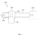
- FIG. 1 is a schematic diagram of an electrically-powered power steering device (100).
- This power steering device (100) is used for assisting the operation of a handle (a steering wheel) in a vehicle such as an automobile.
- the power steering device (100) has a torque sensor (102) which detects the power applied to the handle through an shaft part (101) connected to a steering apparatus (200), a control unit (103) which calculates the necessary assist power based on the output from the torque sensor (102), a motor (50) which generates the rotative force based on the output from the control unit (103), and a reduction mechanism (104) which reduces the rotative force of the motor (50) and delivers the same to the steering apparatus (200).
- a torque sensor (102) which detects the power applied to the handle through an shaft part (101) connected to a steering apparatus (200)
- a control unit (103) which calculates the necessary assist power based on the output from the torque sensor (102)
- a motor (50) which generates the rotative force based
- the motor (50) of the power steering device (100) is operated by the power applied to the handle, and the rotation of the handle is assisted by the rotative force of the motor (50), which makes it possible to operate the handle with a small amount of force.
- FIG. 2 is a schematic diagram of a section of the motor (50).
- the motor (50) is a so called inner-rotor type motor configured with 8 poles and 12 slots.
- the motor (50) comprises a shaft (51), a rotor (52), a stator (1), a bus bar unit (30), and a motor housing (5).
- the stator (1) approximately in a form of a cylinder is provided in the motor housing (5) as illustrated in FIG. 3 .
- the rotor (52) approximately in a form of a cylinder is fixed around the circumference of the shaft (51) which is rotably supported to the motor housing (5).
- the outer circumference surface of the rotor (52) and the inner circumference surface of the stator (1) are facing each other with a slight gap therebetween.
- 8 magnets (54,...,54) (8 poles) are arranged in even intervals around the outer circumference of the rotor (52) so that the N-pole and the S-pole are arranged alternately.
- the stator (1) comprises a core (2), an insulator (3), and a coil (4).
- the core (2) is formed by laminating sheets of steel.
- the core (2) has a ring part (21) in a form of a ring and a teeth part (22).
- the teeth part (22) consists of twelve elemental teeth parts (22a,...,22a) projecting from the inside of the ring part (21) toward the center thereof.
- a conductive line is winded around each elemental teeth part (22a) through the insulator (3), and the coil (4) is formed by so called concentrated winding. That is, a coil group consisting of twelve coils (4,...,4) is formed in the teeth part (22). Further, a conductive line is accommodated within the twelve spaces (slots) (6,...,6) between the adjacent elemental teeth parts (22a) (12 slots).
- the core (2) is formed by coupling the twelve elemental cores (2a,...,2a).
- Each elemental core (2a) is extended to the axial direction and has an external form with an approximately T-shaped section, and each elemental core has an elemental teeth part (22a) (see FIG. 5 ).
- a conductive line is winded to every two elemental teeth parts (22a) to form total six pairs of coils (40,...,40).
- a coil pair (40) connecting two coils (4,4) is formed by consecutively winding a conductive line to each elemental teeth part (22a,22a) with respect to unconnected two elemental cores (2a,2a).
- the winding direction of the two coils (4,4) in each coil pair (40) is arranged in the same direction when viewed from a front end side of the elemental teeth part (22a).
- the winding direction of the two coils (4,4) in each coil pair (40) is arranged in a clockwise direction; however, a counter clockwise direction is also applicable.
- the coil pair (40) consists of two types of coil pairs (40a,40b) where the winding directions of conductive line are different.
- the coil pair (40a) comprises a first coil pair - a third coil pair (41,42,43) where the winding of the two coils (4,4) starts from the left coil (4) and ends at the right coil (4).
- the coil pair (40b) comprises a fourth coil pair - a sixth coil pair (44,45,46) where the winding starts from the right coil (4) and ends at the left coil (4).
- the winding in the first coil pair - the third coil pair (41,42,43) respectively starts from their left coils (41b,42b,43b) and ends at the right coils (41a,42a,43a).
- the winding in the fourth coil pair - the sixth coil pair (44,45,46) starts from their right coils (44b,45b,46b) and ends at the left coils (44a,45a,46a).
- the white circle illustrates a starting end of winding
- the black circle illustrates a finishing end of winding.
- the two types of coil pairs (40a,40b) where the winding directions of conductive line are different can be easily formed, for example, by using the method illustrated in FIG. 5 . That is, one coil pair [40a(40b)] can be formed by bending the coil pair (40) winded in the same direction as the other coil pair [40b(40a)] in an opposite direction at its jumper wire (47) portion and then changing the left and right of each elemental core (2a). Thus, it is desirable to form one coil pair [40a(40b)] first, and then form the other coil pair [40b(40a)] by bending the necessary portion of the coil pair [40a(40b)] for connecting each elemental core (2a), which provides excellent work efficiency.
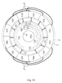
- Each coil pair (40) is installed in a predetermined arrangement so that the motor efficiency is performed suitably for the power steering device (100).
- the core (2) when the core (2) is viewed in its axial direction and virtually divided by a first compartment line (23) into a first region (24) and a second region (25), the first coil pair - the third coil pair (41,42,43) are arranged in the first region (24), and the fourth coil pair - the sixth coil pair (44,45,46) is arranged in the second region (25).
- the coil (42a) of the second coil pair (42) and the coil (43a) of the third coil pair (43) are arranged to be placed between the two coils (41a,41b) of the first coil pair (41). That is, in the first region (24) [or the second region (25)], one coils (4) respectively from another two coil pairs (40) are arranged between the two coils (4,4) of one coil pair (40).
- each coil pair (40) is arranged in a symmetrical form with respect to the first compartment line (23) in the first region (24) and the second region (25).
- the coil (41a), the coil (42a), the coil (43a), the coil (41b), the coil (42b), the coil (43b) are arranged in a counter clockwise direction in said order.
- the coil (44a), the coil (45a), the coil (46a), the coil (44b), the coil (45b), the coil (46b) are arranged in a clockwise direction in said order.
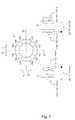
- Such arrangement makes it possible to form a star connection which corresponds to the U-phase, V-phase, W-phase illustrated in FIG. 6 .
- the core (2) is divided by a second compartment line (26) perpendicular to the first compartment line (23) into a phase region and a neutral region equally along the axial direction, one coils (41a,...,46a) of the first coil pair - the sixth coil pair (41,...,46) are arranged in the phase region (27), and the other coils (41b,...,46b) are arranged in the neutral region (28).
- the conductive lines derived from the neutral region (28) can all be connected to a neutral point (N).
- the bus bar unit (30) consists of a plurality of bus bars (32) and a holder (31).
- the holder (31) is an injection molded article made by an insulating resin such as polybutylenetelephthalate (PBT) including fiber.
- the holder (31) comprises a bus bar supporting part (31a) in a form of a ring, a connector part (31b) formed integrally with the bus bar supporting part (31a), and a plurality of supporting leg parts (31c,...,31c) for attaching to the motor housing (5).
- the bus bar (32) is a press processed article of a metal plate with excellent conductivity, such as copper.
- Each bus bar (32) is formed integrally with the holder (31) by a method so called insert molding.
- the bus bar (32) of the present embodiment is extended to the circumferential direction in a strip form and comprises a first bus bar (32a) in an approximate semicircle, and a second bus bar - a fourth bus bar (32b,32c,32d) which is respectively in a form of a minor arc having different lengths.
- a plurality of connecting terminals (33,33,...) is formed to protrude from the outer circumference of each bus bar (32).
- the conductive line derived from the stator (1) is connected to these connecting terminals (33,33,).
- a second - fourth connector terminals (34b,34c,34d) standing approximately perpendicularly are formed integrally at the end of each of the second bus bar - the fourth bus bar (32b,32c,32d).
- the front end of the second - fourth connector terminals (34b,34c,34d) are protruded from the connector part (31b) of each holder (31).
- Each bus bar (32) is embedded in the bus bar supporting part (31a) so as not to contact with each other.
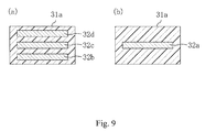
- the bus bar supporting part (31a) is divided into a phase side region (37) and a neutral side region (36) by a bisectrix (35) equally along the axial direction
- the first bus bar (32a) is arranged in the neutral side region (36)
- the second bus bar - the fourth bus bar (32b,32c,32d) are arranged in the phase side region (37).
- the second bus bar - the fourth bus bar are arranged to overlap with each other with a resin layer therebetween.
- FIG. 9(b) only the first bus bar (32a) is arranged in the neutral side region (36).
- the bus bar unit (30) is connected to the stator (1). That is, the neutral side region (36) of the bus bar unit (30) is arranged correspondingly to the neutral region (28) of the stator (1), and the phase side region (37) of the bus bar unit (30) is arranged correspondingly to the phase region (27) of the stator (1). Further, the conductive line derived from the neutral region (28) of the stator (1), specifically, the conductive line derived from the coil (41b), the coil (42b), the coil (43b), the coil (44b), the coil (45b), the coil (46b) is connected to each of the connecting terminals (33,...,33) of the first bus bar (32a).
- the conductive line derived from the phase region (27) of the stator (1) is connected to certain connecting terminals (33,...,33) of the second bus bar - the fourth bus bar (32b,32c,32d).
- the conductive lines derived from the coil (43a) and the coil (44a) are connected to each of the connecting terminals (33,33) of the second bus bar (32b).
- the conductive lines derived from the coil (42a) and the coil (45a) are connected to each of the connecting terminals (33,33) of the third bus bar (32c).
- the conductive lines derived from the coil (41a) and the coil (46a) are connected to each of the connecting terminals (33,33) of the fourth bus bar (32d).
- a neutral point (N) is formed by the first bus bar (32a), and a star connection illustrated in FIG. 6 is formed by each of the contact points (U,V,W) which are formed by the second bus bar - the fourth bus bar (32b,32c,32d).
- FIG. 11 illustrates an example of a conventional bus bar unit.
- the bus bar for the neutral point is shaped in the forms of a ring or a major arc in order to prevent the conductive line from crawling about.
- the bus bar unit (30) of the present embodiment provides the first bus bar (32a) for the neutral point in a form of an approximate semicircle, and the second bus bar - the fourth bus bar (32b,32c,32d) for a contact points of each phase in a form of a minor arc and arranges them respectively in the neutral side region (36) and the phase side region (37) of the bus bar unit (30), which makes it possible to decrease the thickness of the bus bar supporting part and therefore enables the miniaturization of the bus bar unit (30).
- This also provides easy wire connection with the stator (1) and improves work efficiency.
Landscapes
- Engineering & Computer Science (AREA)
- Power Engineering (AREA)
- Chemical & Material Sciences (AREA)
- Combustion & Propulsion (AREA)
- Transportation (AREA)
- Mechanical Engineering (AREA)
- Windings For Motors And Generators (AREA)
- Insulation, Fastening Of Motor, Generator Windings (AREA)
- Power Steering Mechanism (AREA)
Applications Claiming Priority (2)
| Application Number | Priority Date | Filing Date | Title |
|---|---|---|---|
| JP2009039159A JP2010200400A (ja) | 2009-02-23 | 2009-02-23 | ステータ、バスバーユニット、モータ、及びパワーステアリング装置 |
| PCT/JP2010/052756 WO2010095752A1 (fr) | 2009-02-23 | 2010-02-23 | Stator, unité de barre omnibus, moteur et dispositif de direction assistée |
Publications (3)
| Publication Number | Publication Date |
|---|---|
| EP2400635A1 true EP2400635A1 (fr) | 2011-12-28 |
| EP2400635A4 EP2400635A4 (fr) | 2017-05-24 |
| EP2400635B1 EP2400635B1 (fr) | 2019-01-09 |
Family
ID=42634027
Family Applications (1)
| Application Number | Title | Priority Date | Filing Date |
|---|---|---|---|
| EP10743875.6A Active EP2400635B1 (fr) | 2009-02-23 | 2010-02-23 | Stator, unité de barre omnibus, moteur et dispositif de direction assistée |
Country Status (6)
| Country | Link |
|---|---|
| US (1) | US8674578B2 (fr) |
| EP (1) | EP2400635B1 (fr) |
| JP (1) | JP2010200400A (fr) |
| KR (1) | KR101213124B1 (fr) |
| CN (1) | CN102326320B (fr) |
| WO (1) | WO2010095752A1 (fr) |
Cited By (2)
| Publication number | Priority date | Publication date | Assignee | Title |
|---|---|---|---|---|
| WO2020002847A1 (fr) * | 2018-06-27 | 2020-01-02 | Avo Carbon France | Fabrication d'un dispositif de distribution de puissance électrique multiphasée |
| EP4057483A1 (fr) * | 2021-03-09 | 2022-09-14 | Hyundai Mobis Co., Ltd. | Stator pour moteur et moteur le comprenant |
Families Citing this family (42)
| Publication number | Priority date | Publication date | Assignee | Title |
|---|---|---|---|---|
| EP2458715B1 (fr) * | 2010-11-05 | 2014-01-08 | LG Innotek Co., Ltd. | Barre omnibus de moteur EPS |
| JP5813463B2 (ja) * | 2011-11-02 | 2015-11-17 | 株式会社東芝 | 回転電機の固定子、固定子用ホルダ、回転電機、及び自動車 |
| JP5810869B2 (ja) * | 2011-11-28 | 2015-11-11 | トヨタ自動車株式会社 | 回転電機用端末モジュール及びこれを備えた回転電機 |
| JP5939006B2 (ja) * | 2012-04-13 | 2016-06-22 | 株式会社ジェイテクト | 回転電機 |
| KR101992687B1 (ko) * | 2012-06-28 | 2019-06-25 | 엘지이노텍 주식회사 | 모터 |
| US20140014390A1 (en) * | 2012-07-11 | 2014-01-16 | Remy Technologies, Llc | Buss bar assembly having axially stacked buss bar plates |
| JP6135982B2 (ja) * | 2013-01-17 | 2017-05-31 | 日本電産株式会社 | モータ |
| JP6053001B2 (ja) * | 2013-03-08 | 2016-12-27 | Kyb株式会社 | バスバーユニット |
| JP5850264B2 (ja) * | 2013-06-25 | 2016-02-03 | 株式会社デンソー | 回転電機の固定子 |
| US9143022B2 (en) * | 2013-07-29 | 2015-09-22 | General Electric Company | System and method for rebalancing generator rotor in-situ |
| FR3018964B1 (fr) * | 2014-03-24 | 2016-03-04 | Valeo Equip Electr Moteur | Element d'interconnexion pour le branchement des bobines du stator |
| JP6539997B2 (ja) * | 2014-11-25 | 2019-07-10 | 日本電産株式会社 | モータ |
| CN110912341B (zh) | 2016-03-30 | 2022-03-18 | 米沃奇电动工具公司 | 用于电动工具的无刷马达 |
| DE102016225170A1 (de) | 2016-12-15 | 2018-06-21 | Continental Automotive Gmbh | Führungsring zur Anbindung an einem Gehäuse einer elektrischen Maschine |
| WO2018135086A1 (fr) * | 2017-01-18 | 2018-07-26 | パナソニックIpマネジメント株式会社 | Corps de bobine moulé, son procédé de production, moteur et procédé d'assemblage de stator |
| JP2018117489A (ja) * | 2017-01-20 | 2018-07-26 | 日本電産株式会社 | ロータ及びそれを用いたモータ |
| JP2018117490A (ja) * | 2017-01-20 | 2018-07-26 | 日本電産株式会社 | ロータ及びそれを用いたモータ |
| JP6485486B2 (ja) * | 2017-04-26 | 2019-03-20 | 日本電産株式会社 | 三相モータ |
| JP6399144B2 (ja) * | 2017-04-26 | 2018-10-03 | 日本電産株式会社 | モータ |
| GB2563616B (en) | 2017-06-20 | 2021-03-10 | Dyson Technology Ltd | A stator assembly |
| DE102017211168A1 (de) * | 2017-06-30 | 2019-01-03 | Zf Friedrichshafen Ag | Stator-Verschaltungseinrichtung für eine rotierende elektrische Maschine |
| KR101904287B1 (ko) * | 2017-07-03 | 2018-10-04 | 효성전기주식회사 | 단순한 버스바 구조를 갖는 브러쉬리스 모터의 결선방법 |
| KR101904312B1 (ko) * | 2017-07-03 | 2018-10-04 | 효성전기주식회사 | 브러쉬리스 모터의 버스바 배열방법 |
| KR102489299B1 (ko) | 2017-09-06 | 2023-01-17 | 엘지이노텍 주식회사 | 모터 |
| KR20190095748A (ko) * | 2018-02-07 | 2019-08-16 | 엘지이노텍 주식회사 | 모터 |
| WO2020013078A1 (fr) * | 2018-07-13 | 2020-01-16 | 日本電産株式会社 | Moteur et dispositif de direction assistée électrique |
| KR20200008835A (ko) * | 2018-07-17 | 2020-01-29 | 현대자동차주식회사 | 차량 구동모터의 코일 결선 유닛 및 이의 제조 방법 |
| WO2020039961A1 (fr) * | 2018-08-20 | 2020-02-27 | 日本電産株式会社 | Moteur, dispositif de direction assistée électrique, procédé de fabrication de moteur, unité de barre omnibus et procédé de fabrication d'unité de barre omnibus |
| KR20200029876A (ko) * | 2018-09-11 | 2020-03-19 | 엘지이노텍 주식회사 | 모터 |
| JPWO2020261866A1 (fr) * | 2019-06-28 | 2020-12-30 | ||
| WO2021031783A1 (fr) * | 2019-08-20 | 2021-02-25 | 安徽威灵汽车部件有限公司 | Barre omnibus, corps principal de barre omnibus, moteur, système de direction assistée électrique et véhicule |
| KR102860217B1 (ko) | 2020-01-03 | 2025-09-16 | 엘지이노텍 주식회사 | 모터 |
| WO2021247954A1 (fr) | 2020-06-05 | 2021-12-09 | Milwaukee Electric Tool Corporation | Moteur sans balais pour outil électrique |
| CN112737182B (zh) * | 2020-12-10 | 2022-06-14 | 宜兴华永电机有限公司 | 一种提高双馈发电机定子槽利用率的嵌线方法 |
| JP7109610B1 (ja) * | 2021-02-19 | 2022-07-29 | 三菱電機株式会社 | 回転電機の固定子及びそのコイル接続装置 |
| JP7700661B2 (ja) * | 2021-12-16 | 2025-07-01 | 株式会社豊田自動織機 | 回転電機 |
| JP7358681B1 (ja) * | 2021-12-27 | 2023-10-10 | 日本発條株式会社 | ステータ |
| JP2023176648A (ja) * | 2022-05-31 | 2023-12-13 | 株式会社デンソー | 固定子の組み付け方法、および、固定子の組み付け装置 |
| CN117856499A (zh) * | 2022-09-30 | 2024-04-09 | 日本电产株式会社 | 马达 |
| WO2024216262A1 (fr) | 2023-04-14 | 2024-10-17 | Garner Development Services, Llc | Moteur électrique sans boîtier doté d'un arbre fixe pour des environnements marins |
| WO2024227054A1 (fr) | 2023-04-27 | 2024-10-31 | Garner Development Services, Llc | Système de propulsion de pompe à jet |
| JP2025023736A (ja) * | 2023-08-04 | 2025-02-17 | 株式会社ミツバ | モータ |
Family Cites Families (12)
| Publication number | Priority date | Publication date | Assignee | Title |
|---|---|---|---|---|
| JP3017085B2 (ja) * | 1995-11-02 | 2000-03-06 | 三菱電機株式会社 | 回転電機及びその製造方法 |
| JP3623683B2 (ja) * | 1999-03-09 | 2005-02-23 | 山洋電気株式会社 | 回転電機用ステータの製造方法及び回転電機用ステータ |
| JP3735250B2 (ja) | 2000-12-22 | 2006-01-18 | 株式会社ミツバ | 電機子の巻線構造 |
| CN100411279C (zh) * | 2002-07-22 | 2008-08-13 | 日本精工株式会社 | 3相永磁铁电动机 |
| JP4112535B2 (ja) | 2004-07-30 | 2008-07-02 | 株式会社一宮電機 | ステータ及びブラシレスモータ |
| JP4662200B2 (ja) * | 2004-09-29 | 2011-03-30 | 日本電産株式会社 | モータおよびブスバー |
| JP4916730B2 (ja) * | 2006-02-07 | 2012-04-18 | アスモ株式会社 | ステータの製造方法及びステータ |
| JP5217117B2 (ja) * | 2006-06-05 | 2013-06-19 | 日本電産株式会社 | ブラシレスモータ |
| JP4251196B2 (ja) * | 2006-06-16 | 2009-04-08 | トヨタ自動車株式会社 | ステアリング装置用モータ |
| JP2008284912A (ja) * | 2007-05-15 | 2008-11-27 | Jtekt Corp | 車両用操舵装置 |
| JP2009027777A (ja) * | 2007-07-17 | 2009-02-05 | Jtekt Corp | 永久磁石型ブラシレスモータ |
| US7893587B2 (en) * | 2008-10-23 | 2011-02-22 | Electromag Sa | Brushless DC electric motor |
-
2009
- 2009-02-23 JP JP2009039159A patent/JP2010200400A/ja active Pending
-
2010
- 2010-02-23 KR KR1020117008585A patent/KR101213124B1/ko active Active
- 2010-02-23 CN CN201080008915.7A patent/CN102326320B/zh active Active
- 2010-02-23 WO PCT/JP2010/052756 patent/WO2010095752A1/fr not_active Ceased
- 2010-02-23 EP EP10743875.6A patent/EP2400635B1/fr active Active
- 2010-02-23 US US13/202,631 patent/US8674578B2/en active Active
Non-Patent Citations (1)
| Title |
|---|
| See references of WO2010095752A1 * |
Cited By (4)
| Publication number | Priority date | Publication date | Assignee | Title |
|---|---|---|---|---|
| WO2020002847A1 (fr) * | 2018-06-27 | 2020-01-02 | Avo Carbon France | Fabrication d'un dispositif de distribution de puissance électrique multiphasée |
| FR3083387A1 (fr) * | 2018-06-27 | 2020-01-03 | Avo Carbon France | Fabrication d'un dispositif de distribution de puissance electrique multiphasee |
| EP4057483A1 (fr) * | 2021-03-09 | 2022-09-14 | Hyundai Mobis Co., Ltd. | Stator pour moteur et moteur le comprenant |
| US12184141B2 (en) | 2021-03-09 | 2024-12-31 | Hyundai Mobis Co., Ltd. | Stator for motor and motor including the same |
Also Published As
| Publication number | Publication date |
|---|---|
| WO2010095752A1 (fr) | 2010-08-26 |
| CN102326320B (zh) | 2014-06-25 |
| JP2010200400A (ja) | 2010-09-09 |
| KR20110069088A (ko) | 2011-06-22 |
| EP2400635B1 (fr) | 2019-01-09 |
| EP2400635A4 (fr) | 2017-05-24 |
| KR101213124B1 (ko) | 2012-12-20 |
| US8674578B2 (en) | 2014-03-18 |
| US20110297474A1 (en) | 2011-12-08 |
| CN102326320A (zh) | 2012-01-18 |
Similar Documents
| Publication | Publication Date | Title |
|---|---|---|
| EP2400635B1 (fr) | Stator, unité de barre omnibus, moteur et dispositif de direction assistée | |
| US9079603B2 (en) | Motor for an electric power steering apparatus | |
| CN106410995B (zh) | 用于旋转电机的定子 | |
| US10211699B2 (en) | Motor and bus bar unit having overlapping bridge portions | |
| JP6267907B2 (ja) | バスバーユニットおよびブラシレスモータ | |
| CN101527486B (zh) | 无刷马达 | |
| US9397541B2 (en) | Stator for electric rotating machine and method of manufacturing the same | |
| EP2273654A2 (fr) | Machine électrique tournante et son procédé de fabrication | |
| US8896189B2 (en) | Stator for electric rotating machine and method of manufacturing the same | |
| US7825561B2 (en) | Motor with simplified structure and related control device | |
| EP2928048A1 (fr) | Moteur électrique | |
| CN103973006B (zh) | 转子、定子以及电动机 | |
| JP2005287240A (ja) | 同期電動機 | |
| CN103107625A (zh) | 旋转电机及其定子线圈的接线单元的制造方法 | |
| EP3032717A1 (fr) | Moteur sans balais | |
| EP2445088A2 (fr) | Moteur sans balai et système de direction assistée électrique | |
| CN103390985B (zh) | 无刷电机和无刷电机的制造方法 | |
| CN112673555B (zh) | 马达 | |
| CN111699616B (zh) | 马达 | |
| JP2014007939A (ja) | ブラシレスモータ | |
| CN103715788B (zh) | 电动机的定子及电动机 | |
| US20190131840A1 (en) | Rotary Electric Machine | |
| WO2021064883A1 (fr) | Machine électrique rotative | |
| JP5787005B2 (ja) | モータ、および、パワーステアリング装置 | |
| JP4726526B2 (ja) | ブラシレスモータ |
Legal Events
| Date | Code | Title | Description |
|---|---|---|---|
| PUAI | Public reference made under article 153(3) epc to a published international application that has entered the european phase |
Free format text: ORIGINAL CODE: 0009012 |
|
| 17P | Request for examination filed |
Effective date: 20110803 |
|
| AK | Designated contracting states |
Kind code of ref document: A1 Designated state(s): AT BE BG CH CY CZ DE DK EE ES FI FR GB GR HR HU IE IS IT LI LT LU LV MC MK MT NL NO PL PT RO SE SI SK SM TR |
|
| DAX | Request for extension of the european patent (deleted) | ||
| RA4 | Supplementary search report drawn up and despatched (corrected) |
Effective date: 20170424 |
|
| RIC1 | Information provided on ipc code assigned before grant |
Ipc: H02K 3/52 20060101ALI20170418BHEP Ipc: H02K 3/28 20060101ALI20170418BHEP Ipc: H02K 3/18 20060101ALN20170418BHEP Ipc: B62D 5/04 20060101AFI20170418BHEP |
|
| STAA | Information on the status of an ep patent application or granted ep patent |
Free format text: STATUS: EXAMINATION IS IN PROGRESS |
|
| 17Q | First examination report despatched |
Effective date: 20180202 |
|
| REG | Reference to a national code |
Ref country code: DE Ref legal event code: R079 Ref document number: 602010056419 Country of ref document: DE Free format text: PREVIOUS MAIN CLASS: H02K0003180000 Ipc: B62D0005040000 |
|
| GRAP | Despatch of communication of intention to grant a patent |
Free format text: ORIGINAL CODE: EPIDOSNIGR1 |
|
| STAA | Information on the status of an ep patent application or granted ep patent |
Free format text: STATUS: GRANT OF PATENT IS INTENDED |
|
| RIC1 | Information provided on ipc code assigned before grant |
Ipc: B62D 5/04 20060101AFI20180629BHEP Ipc: H02K 3/28 20060101ALI20180629BHEP Ipc: H02K 3/52 20060101ALI20180629BHEP Ipc: H02K 3/18 20060101ALN20180629BHEP |
|
| INTG | Intention to grant announced |
Effective date: 20180720 |
|
| GRAS | Grant fee paid |
Free format text: ORIGINAL CODE: EPIDOSNIGR3 |
|
| GRAA | (expected) grant |
Free format text: ORIGINAL CODE: 0009210 |
|
| STAA | Information on the status of an ep patent application or granted ep patent |
Free format text: STATUS: THE PATENT HAS BEEN GRANTED |
|
| AK | Designated contracting states |
Kind code of ref document: B1 Designated state(s): AT BE BG CH CY CZ DE DK EE ES FI FR GB GR HR HU IE IS IT LI LT LU LV MC MK MT NL NO PL PT RO SE SI SK SM TR |
|
| REG | Reference to a national code |
Ref country code: GB Ref legal event code: FG4D |
|
| REG | Reference to a national code |
Ref country code: CH Ref legal event code: EP Ref country code: AT Ref legal event code: REF Ref document number: 1086913 Country of ref document: AT Kind code of ref document: T Effective date: 20190115 |
|
| REG | Reference to a national code |
Ref country code: DE Ref legal event code: R096 Ref document number: 602010056419 Country of ref document: DE |
|
| REG | Reference to a national code |
Ref country code: IE Ref legal event code: FG4D |
|
| REG | Reference to a national code |
Ref country code: NL Ref legal event code: MP Effective date: 20190109 |
|
| REG | Reference to a national code |
Ref country code: LT Ref legal event code: MG4D |
|
| PG25 | Lapsed in a contracting state [announced via postgrant information from national office to epo] |
Ref country code: NL Free format text: LAPSE BECAUSE OF FAILURE TO SUBMIT A TRANSLATION OF THE DESCRIPTION OR TO PAY THE FEE WITHIN THE PRESCRIBED TIME-LIMIT Effective date: 20190109 |
|
| REG | Reference to a national code |
Ref country code: AT Ref legal event code: MK05 Ref document number: 1086913 Country of ref document: AT Kind code of ref document: T Effective date: 20190109 |
|
| PG25 | Lapsed in a contracting state [announced via postgrant information from national office to epo] |
Ref country code: ES Free format text: LAPSE BECAUSE OF FAILURE TO SUBMIT A TRANSLATION OF THE DESCRIPTION OR TO PAY THE FEE WITHIN THE PRESCRIBED TIME-LIMIT Effective date: 20190109 Ref country code: PT Free format text: LAPSE BECAUSE OF FAILURE TO SUBMIT A TRANSLATION OF THE DESCRIPTION OR TO PAY THE FEE WITHIN THE PRESCRIBED TIME-LIMIT Effective date: 20190509 Ref country code: SE Free format text: LAPSE BECAUSE OF FAILURE TO SUBMIT A TRANSLATION OF THE DESCRIPTION OR TO PAY THE FEE WITHIN THE PRESCRIBED TIME-LIMIT Effective date: 20190109 Ref country code: PL Free format text: LAPSE BECAUSE OF FAILURE TO SUBMIT A TRANSLATION OF THE DESCRIPTION OR TO PAY THE FEE WITHIN THE PRESCRIBED TIME-LIMIT Effective date: 20190109 Ref country code: LT Free format text: LAPSE BECAUSE OF FAILURE TO SUBMIT A TRANSLATION OF THE DESCRIPTION OR TO PAY THE FEE WITHIN THE PRESCRIBED TIME-LIMIT Effective date: 20190109 Ref country code: FI Free format text: LAPSE BECAUSE OF FAILURE TO SUBMIT A TRANSLATION OF THE DESCRIPTION OR TO PAY THE FEE WITHIN THE PRESCRIBED TIME-LIMIT Effective date: 20190109 Ref country code: NO Free format text: LAPSE BECAUSE OF FAILURE TO SUBMIT A TRANSLATION OF THE DESCRIPTION OR TO PAY THE FEE WITHIN THE PRESCRIBED TIME-LIMIT Effective date: 20190409 |
|
| PG25 | Lapsed in a contracting state [announced via postgrant information from national office to epo] |
Ref country code: BG Free format text: LAPSE BECAUSE OF FAILURE TO SUBMIT A TRANSLATION OF THE DESCRIPTION OR TO PAY THE FEE WITHIN THE PRESCRIBED TIME-LIMIT Effective date: 20190409 Ref country code: IS Free format text: LAPSE BECAUSE OF FAILURE TO SUBMIT A TRANSLATION OF THE DESCRIPTION OR TO PAY THE FEE WITHIN THE PRESCRIBED TIME-LIMIT Effective date: 20190509 Ref country code: GR Free format text: LAPSE BECAUSE OF FAILURE TO SUBMIT A TRANSLATION OF THE DESCRIPTION OR TO PAY THE FEE WITHIN THE PRESCRIBED TIME-LIMIT Effective date: 20190410 Ref country code: LV Free format text: LAPSE BECAUSE OF FAILURE TO SUBMIT A TRANSLATION OF THE DESCRIPTION OR TO PAY THE FEE WITHIN THE PRESCRIBED TIME-LIMIT Effective date: 20190109 Ref country code: HR Free format text: LAPSE BECAUSE OF FAILURE TO SUBMIT A TRANSLATION OF THE DESCRIPTION OR TO PAY THE FEE WITHIN THE PRESCRIBED TIME-LIMIT Effective date: 20190109 |
|
| REG | Reference to a national code |
Ref country code: CH Ref legal event code: PL |
|
| REG | Reference to a national code |
Ref country code: DE Ref legal event code: R097 Ref document number: 602010056419 Country of ref document: DE |
|
| PG25 | Lapsed in a contracting state [announced via postgrant information from national office to epo] |
Ref country code: CZ Free format text: LAPSE BECAUSE OF FAILURE TO SUBMIT A TRANSLATION OF THE DESCRIPTION OR TO PAY THE FEE WITHIN THE PRESCRIBED TIME-LIMIT Effective date: 20190109 Ref country code: RO Free format text: LAPSE BECAUSE OF FAILURE TO SUBMIT A TRANSLATION OF THE DESCRIPTION OR TO PAY THE FEE WITHIN THE PRESCRIBED TIME-LIMIT Effective date: 20190109 Ref country code: IT Free format text: LAPSE BECAUSE OF FAILURE TO SUBMIT A TRANSLATION OF THE DESCRIPTION OR TO PAY THE FEE WITHIN THE PRESCRIBED TIME-LIMIT Effective date: 20190109 Ref country code: SK Free format text: LAPSE BECAUSE OF FAILURE TO SUBMIT A TRANSLATION OF THE DESCRIPTION OR TO PAY THE FEE WITHIN THE PRESCRIBED TIME-LIMIT Effective date: 20190109 Ref country code: MC Free format text: LAPSE BECAUSE OF FAILURE TO SUBMIT A TRANSLATION OF THE DESCRIPTION OR TO PAY THE FEE WITHIN THE PRESCRIBED TIME-LIMIT Effective date: 20190109 Ref country code: AT Free format text: LAPSE BECAUSE OF FAILURE TO SUBMIT A TRANSLATION OF THE DESCRIPTION OR TO PAY THE FEE WITHIN THE PRESCRIBED TIME-LIMIT Effective date: 20190109 Ref country code: DK Free format text: LAPSE BECAUSE OF FAILURE TO SUBMIT A TRANSLATION OF THE DESCRIPTION OR TO PAY THE FEE WITHIN THE PRESCRIBED TIME-LIMIT Effective date: 20190109 Ref country code: EE Free format text: LAPSE BECAUSE OF FAILURE TO SUBMIT A TRANSLATION OF THE DESCRIPTION OR TO PAY THE FEE WITHIN THE PRESCRIBED TIME-LIMIT Effective date: 20190109 Ref country code: LU Free format text: LAPSE BECAUSE OF NON-PAYMENT OF DUE FEES Effective date: 20190223 |
|
| PLBE | No opposition filed within time limit |
Free format text: ORIGINAL CODE: 0009261 |
|
| STAA | Information on the status of an ep patent application or granted ep patent |
Free format text: STATUS: NO OPPOSITION FILED WITHIN TIME LIMIT |
|
| REG | Reference to a national code |
Ref country code: BE Ref legal event code: MM Effective date: 20190228 |
|
| REG | Reference to a national code |
Ref country code: IE Ref legal event code: MM4A |
|
| PG25 | Lapsed in a contracting state [announced via postgrant information from national office to epo] |
Ref country code: SM Free format text: LAPSE BECAUSE OF FAILURE TO SUBMIT A TRANSLATION OF THE DESCRIPTION OR TO PAY THE FEE WITHIN THE PRESCRIBED TIME-LIMIT Effective date: 20190109 |
|
| 26N | No opposition filed |
Effective date: 20191010 |
|
| GBPC | Gb: european patent ceased through non-payment of renewal fee |
Effective date: 20190409 |
|
| PG25 | Lapsed in a contracting state [announced via postgrant information from national office to epo] |
Ref country code: CH Free format text: LAPSE BECAUSE OF NON-PAYMENT OF DUE FEES Effective date: 20190228 Ref country code: LI Free format text: LAPSE BECAUSE OF NON-PAYMENT OF DUE FEES Effective date: 20190228 |
|
| PG25 | Lapsed in a contracting state [announced via postgrant information from national office to epo] |
Ref country code: GB Free format text: LAPSE BECAUSE OF NON-PAYMENT OF DUE FEES Effective date: 20190409 Ref country code: IE Free format text: LAPSE BECAUSE OF NON-PAYMENT OF DUE FEES Effective date: 20190223 |
|
| PG25 | Lapsed in a contracting state [announced via postgrant information from national office to epo] |
Ref country code: SI Free format text: LAPSE BECAUSE OF FAILURE TO SUBMIT A TRANSLATION OF THE DESCRIPTION OR TO PAY THE FEE WITHIN THE PRESCRIBED TIME-LIMIT Effective date: 20190109 Ref country code: BE Free format text: LAPSE BECAUSE OF NON-PAYMENT OF DUE FEES Effective date: 20190228 Ref country code: FR Free format text: LAPSE BECAUSE OF NON-PAYMENT OF DUE FEES Effective date: 20190309 |
|
| PG25 | Lapsed in a contracting state [announced via postgrant information from national office to epo] |
Ref country code: TR Free format text: LAPSE BECAUSE OF FAILURE TO SUBMIT A TRANSLATION OF THE DESCRIPTION OR TO PAY THE FEE WITHIN THE PRESCRIBED TIME-LIMIT Effective date: 20190109 |
|
| PG25 | Lapsed in a contracting state [announced via postgrant information from national office to epo] |
Ref country code: MT Free format text: LAPSE BECAUSE OF NON-PAYMENT OF DUE FEES Effective date: 20190223 |
|
| PG25 | Lapsed in a contracting state [announced via postgrant information from national office to epo] |
Ref country code: CY Free format text: LAPSE BECAUSE OF FAILURE TO SUBMIT A TRANSLATION OF THE DESCRIPTION OR TO PAY THE FEE WITHIN THE PRESCRIBED TIME-LIMIT Effective date: 20190109 |
|
| PG25 | Lapsed in a contracting state [announced via postgrant information from national office to epo] |
Ref country code: HU Free format text: LAPSE BECAUSE OF FAILURE TO SUBMIT A TRANSLATION OF THE DESCRIPTION OR TO PAY THE FEE WITHIN THE PRESCRIBED TIME-LIMIT; INVALID AB INITIO Effective date: 20100223 |
|
| PG25 | Lapsed in a contracting state [announced via postgrant information from national office to epo] |
Ref country code: MK Free format text: LAPSE BECAUSE OF FAILURE TO SUBMIT A TRANSLATION OF THE DESCRIPTION OR TO PAY THE FEE WITHIN THE PRESCRIBED TIME-LIMIT Effective date: 20190109 |
|
| P01 | Opt-out of the competence of the unified patent court (upc) registered |
Effective date: 20230519 |
|
| PGFP | Annual fee paid to national office [announced via postgrant information from national office to epo] |
Ref country code: DE Payment date: 20260217 Year of fee payment: 17 |