EP2406166B1 - Aufzugssystemtürrahmen, der führungsschienen stützt - Google Patents
Aufzugssystemtürrahmen, der führungsschienen stützt Download PDFInfo
- Publication number
- EP2406166B1 EP2406166B1 EP09841626.6A EP09841626A EP2406166B1 EP 2406166 B1 EP2406166 B1 EP 2406166B1 EP 09841626 A EP09841626 A EP 09841626A EP 2406166 B1 EP2406166 B1 EP 2406166B1
- Authority
- EP
- European Patent Office
- Prior art keywords
- guide rail
- door frame
- hoistway
- door frames
- brackets
- Prior art date
- Legal status (The legal status is an assumption and is not a legal conclusion. Google has not performed a legal analysis and makes no representation as to the accuracy of the status listed.)
- Not-in-force
Links
- 238000009434 installation Methods 0.000 claims description 12
- 238000000034 method Methods 0.000 claims description 9
- 230000001419 dependent effect Effects 0.000 description 1
Images

Classifications
-
- B—PERFORMING OPERATIONS; TRANSPORTING
- B66—HOISTING; LIFTING; HAULING
- B66B—ELEVATORS; ESCALATORS OR MOVING WALKWAYS
- B66B13/00—Doors, gates, or other apparatus controlling access to, or exit from, cages or lift well landings
- B66B13/30—Constructional features of doors or gates
- B66B13/306—Details of door jambs
-
- B—PERFORMING OPERATIONS; TRANSPORTING
- B66—HOISTING; LIFTING; HAULING
- B66B—ELEVATORS; ESCALATORS OR MOVING WALKWAYS
- B66B7/00—Other common features of elevators
- B66B7/02—Guideways; Guides
- B66B7/023—Mounting means therefor
-
- Y—GENERAL TAGGING OF NEW TECHNOLOGICAL DEVELOPMENTS; GENERAL TAGGING OF CROSS-SECTIONAL TECHNOLOGIES SPANNING OVER SEVERAL SECTIONS OF THE IPC; TECHNICAL SUBJECTS COVERED BY FORMER USPC CROSS-REFERENCE ART COLLECTIONS [XRACs] AND DIGESTS
- Y10—TECHNICAL SUBJECTS COVERED BY FORMER USPC
- Y10T—TECHNICAL SUBJECTS COVERED BY FORMER US CLASSIFICATION
- Y10T29/00—Metal working
- Y10T29/49—Method of mechanical manufacture
- Y10T29/49826—Assembling or joining
Definitions
- Elevator systems typically include a car that travels vertically within a hoistway to carry passengers, cargo or both between various levels in a building.
- the path the car follows is established, in part, by guide rails that are installed in a hoistway. Installing the guide rails and aligning them in proper position within a hoistway is one of the more time-consuming aspects of installing an elevator system.
- Guide rails must be aligned relative to each other and vertically plumbed within the hoistway, for example Additionally, the guide rail positions must be set relative to entranceways that are installed at each landing along the hoistway.
- the relative positions of the guide rails and the entranceways establishes the position of the elevator car relative to the entranceways at each landing. Having appropriate alignment at those locations is necessary to achieve adequate door engagement between the elevator car doors and the hoistway doors. Additionally, the elevator car must be precisely positioned relative to the landings to facilitate passenger movement between the landings and the interior of the elevator car. There must be sufficient clearance and alignment in order for the elevator car to be able to move through the hoistway while still keeping a small enough gap between the elevator car structure and the entranceway structures.
- An exemplary elevator door frame comprises a sill member; a header member; a plurality of jamb members between the sill member and the header member; a plurality of guide rail brackets supported on at least one of the sill member, header member or one of the jamb members, wherein the guide rail brackets is being configured to receive a portion of a guide rail; and at least one guide rail section, which is secured in a desired position relative to the door frame by the guide rail brackets.
- the guide rail section comprises a first portion that remains in a fixed position relative to the door frame and a second portion that is moveable relative to the first portion.
- An exemplary elevator system includes a hoistway.
- a plurality of door frames according to an exemplary embodiment of the invention are supported at selected locations along a selected wall of the hoistway such that there is vertical spacing between one of the header members at a first landing and an adjacent one of the sill members at a second, different landing.
- a plurality of guide rails are supported by the door frames in desired positions along the selected wall.
- An exemplary method of installing elevator system components includes installing door frames that each have a header member, a sill member and jamb members in selected locations along a selected wall of a hoistway.
- Guide rails comprising a first portion that remains in a fixed position relative to the door frame and a second portion that is moveable relative to the first portion are secured in desired positions along the selected wall by supporting the guide rails on the installed door frames.
- the method further includes moving the second portion into a position aligned with the first portion such that the second portion of one guide rail section contacts a first portion of a vertically adjacent guide rail section when in the position aligned with the first portion.
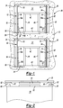
- Figure 1 schematically shows selected portions of an elevator system 20.
- a wall 22 of a hoistway includes a plurality of openings 24 that are useful for establishing access points to the elevator system from landings or building floors 26.
- the illustration in Figure 1 is seen from a perspective inside of the hoistway and the example hoistway wall 22 is a front wall of the hoistway.
- each door frame 30 is associated with each opening 24.
- each door frame includes a main header 32, a main sill 34 and jamb members 36 and 38.
- a finish doorway is established in this example, in part, by a door header 40, a door sill member 42 and door jambs 44 and 46.
- the headers and sills are horizontally oriented while the jamb members are all vertically oriented.
- the door frames 30 include guide rails brackets 50 for securing guide rails 52 in desired locations in the hoistway.
- the guide rails 52 are supported directly by the door frames 30 by being mounted on or secured to at least one of a header 32, 40, a sill 34, 42 or a jamb member 36, 38, 44, 46.
- the guide rail brackets 50 in this example are secured to the main header 32, the sill 34 and the jamb members 36 and 38.
- this position of the guide rails 52 places them near an outside edge of a front of an elevator car 60.
- Elevator car doors 62 are supported for movement in a known manner along the front of the elevator car 60.
- the elevator car doors 62 interact with hoistway doors 64 supported at each of the landings for movement relative to a corresponding door frame 30.
- guiding devices 66 follow along the guide rails 52 for guiding movement of the elevator car 60.
- the guiding devices 66 may comprise rollers or sliding members as known in the art.
- the guide rails 52 are along the front wall 22 or surface of the hoistway, which is the wall facing the car doors 62 on the elevator car 60.
- Providing the guide rails on the front wall is unique as most elevator systems position guide rails on the sides of the elevator car.
- Providing the guide rails in the position of the illustrated example facilitates supporting the guide rails directly by the door frames 30 by securing or mounting the guide rails to one of the door frame members (e.g., the header, sill or jamb members).
- FIG. 1 schematically shows one example arrangement in which the guide rails 52 comprise a plurality of sections.
- Each door frame 30 has two associated sections that can be pre-mounted to the door frames 30 prior to installation.
- each guide rail section includes a first portion 52a that remains fixed relative to the door frame 30 and a second portion 52b that is moveable relative to the first portion 52a.
- the second portions 52b are moveable about a hinge or pivot point from a position (illustrated in Figure 1 ) that is useful for shipping and installation of the door frame 30 into an installed position (shown in phantom) in which the second portion 52b is aligned with the remainder of the guide rail 52.
- the second portions 52b effectively extend the length of the guide rail section associated with each door frame 30.
- the second portions 52b span a gap or spacing between adjacent guide rail sections associated with adjacent door frames 30.
- the second portions 52b of one guide rail section contacts a first (e.g., fixed) portion 52a of a vertically adjacent guide rail section when the second portion 52b is moved into the position aligned with its corresponding first portion of that guide rail section.
- the brackets 50 in this example are strategically positioned to secure the second portions 52b in the aligned, installed positions (shown in phantom in Figure 1 ) for purposes of completing the installation of the guide rails 52.
- the guide rails 52 have longer sections that span more than one entranceway or door frame 30 in a vertical direction.
- the guide rails 52 span the entire length of the hoistway in a conventional manner.
- the guide rail brackets 50 are pre-installed on the door frames 30 to establish the desired alignment of the guide rails 52. Once a sufficient number of the door frames 30 have been installed, the guide rails 52 having sections that are longer than the height of any one of the door frames 30 can then be installed within the hoistway.
- the second portions 52b are not secured to the fixed portions of the guide rail sections that are supported on the corresponding door frame 30 prior to installation of the door frame 30.
- the second portions 52b are separate pieces that are moved into the position (shown in phantom) to span the gap or spacing between adjacent guide rail sections.
- adjustment members 70 such as jack-screws that allow for adjusting the position of the brackets 50 relative to the corresponding door frame 30 (or to adjust the position of a door frame member) to accommodate for any misalignment issues presented during installation of the individual door frames 30.
- adjustment members 70 such as jack-screws that allow for adjusting the position of the brackets 50 relative to the corresponding door frame 30 (or to adjust the position of a door frame member) to accommodate for any misalignment issues presented during installation of the individual door frames 30.
- Such fine-tuning adjustments are more readily accomplished than the multiple adjustments required when attempting to install elevator guide rails in a conventional fashion.
- each guide rail bracket 50 is consistent along the hoistway since they are preassembled onto the corresponding door frame members at a factory, for example. This is in contrast to conventional arrangements where guide rail brackets are secured to hoistway walls along the height of the hoistway and there may be variations in the robustness of the installation of each bracket due to the condition of the hoistway walls or installer ability.
- Another feature of the disclosed examples is that once at least some of the door frames 30 are installed and aligned, the guide rails 52 are automatically aligned by association with the door frames 30. It is possible as in some of the illustrated arrangements to have guide rail sections preinstalled on the door frames, which can facilitate faster installation time.
- One of the main features of the disclosed examples is that they significantly reduce the amount of time it takes to install an elevator system by eliminating the time-consuming difficulties and procedures that were required when installing guide rails in a conventional manner.
Landscapes
- Elevator Door Apparatuses (AREA)
- Wing Frames And Configurations (AREA)
- Lift-Guide Devices, And Elevator Ropes And Cables (AREA)
Claims (11)
- Aufzugtürrahmen (30), der Folgendes umfasst:ein Schwellenelement (34; 42);ein Querholmelement (32; 40)eine Mehrzahl von Pfostenelementen (36; 38; 44, 46) zwischen dem Schwellenelement und dem Querholmelement;eine Mehrzahl von Führungsschienenhalterungen (50), die von dem des Schwellenelement (34; 42), und/oder dem Querholmelement (32; 40) und/oder einem der Pfostenelemente (36; 38; 44; 46) gestützt sind, wobei die Führungsschienenhalterungen (50) dazu konfiguriert sind, einen Abschnitt einer Führungsschiene (52) aufzunehmen; undmindestens einen Führungsschienenabschnitt (52), der in einer gewünschten Position relativ zu dem Türrahmen (30) durch die Führungsschienenhalterungen (50) befestigt ist;dadurch gekennzeichnet, dass der Führungsschienenabschnitt (52) einen ersten Abschnitt (52a) umfasst, der in einer feststehenden Position relativ zu dem Türrahmen (30) bleibt, und einen zweiten Abschnitt (52b) umfasst, der relativ zu dem ersten Abschnitt (52a) beweglich ist.
- Aufzugtürrahmen (30) nach Anspruch 1, der mindestens vier Führungsschienenhalterungen (50) umfasst, wobei zwei der Halterungen (50) auf einer Seite einer Öffnung liegen, die von dem Türrahmen (30) definiert ist, und zwei andere der Halterungen (50) auf einer gegenüberliegenden Seite der Öffnung derart liegen, dass die Halterungen (50) dazu angeordnet sind, Abschnitte einer Führungsschiene (52) auf jeder Seite der Öffnung aufzunehmen.
- Aufzugtürrahmen (30) nach Anspruch 2, wobei der zweite Abschnitt (52b) in eine Position beweglich ist, die mit dem ersten Abschnitt (52a) fluchtet ist, und wobei der zweite Abschnitt (52b) eine Länge des Führungsschienenabschnitts (52) relativ zu dem Türrahmen (30) wirksam erhöht, wenn der zweite Abschnitt (52b) mit dem ersten Abschnitt (52a) ausgerichtet ist.
- Aufzugtürrahmen (30) nach Anspruch 3, wobei der zweite Abschnitt (52b) über ein Scharnier an dem zweiten Abschnitt (52a) befestigt ist.
- Aufzugsystem (20), das Folgendes umfasst:einen Schacht;eine Mehrzahl von Türrahmen (30) nach einem der Ansprüche 1 bis 4, wobei die Türrahmen (30) an ausgewählten Stellen entlang einer ausgewählten Wand (22) des Schachts derart gestützt sind, dass es einen vertikalen Abstand zwischen einem der Querholmelemente (32) an einem ersten Absatz und einem benachbarten der Schwellenelemente (34) an einem zweiten, unterschiedlichen Absatz gibt; undeine Mehrzahl von Führungsschienenabschnitten (52), die von einem entsprechenden der Türrahmen (30) in gewünschten Positionen entlang der ausgewählten Wand (22) gestützt sind.
- Aufzugsystem (20) nach Anspruch 5, wobei eine Position eines jeweiligen Türrahmens (30) relativ zu der ausgewählten Wand (22) des Schachts derart gewählt ist, dass automatisch die Führungsschienen (52) in einer gewünschten Orientierung in dem Schacht nach Einbauen der Türrahmen (30) ausgerichtet sind.
- Verfahren zum Einbauen von Aufzugsystemkomponenten, das die folgenden Schritte umfasst:Einbauen der Türrahmen (30), die jeweils ein Querholmelement (32; 40), ein Schwellenelement (34; 42) und Pfostenelemente (36; 38; 44; 46) an ausgewählten Stellen entlang einer ausgewählten Wand (22) eines Schachts aufweisen;Befestigen von Führungsschienenabschnitten (52) an gewünschten Positionen entlang der ausgewählten Wand (22) durch Befestigen von mindestens einem Führungsschienenabschnitt (52) an jedem der Türrahmen (30) vor dem Einbauen der Türrahmen (30); unddie Führungsschienenabschnitte (52) jeweils einen ersten Abschnitt (52a) umfassen, der in einer festgestellten Position relativ zu dem entsprechenden Türrahmen (30) bleibt, und einen zweiten Abschnitt (52b) umfassen, der relativ zu dem ersten Abschnitt (52a) beweglich ist, und dadurch, dassdas Verfahren Bewegen des zweiten Abschnitts (52b) in eine Position umfasst, die mit dem ersten Abschnitt (52a) derart ausgerichtet ist, dass der zweite Abschnitt (52b) des einen Führungsschienenabschnitts (52) einen ersten Abschnitt (52a) eines vertikal benachbarten Führungsschienenabschnitts (52) berührt, wenn die Position mit dem ersten Abschnitt ausgerichtet ist.
- Verfahren nach Anspruch 7, das Folgendes umfasst:Befestigen der Führungsschienenhalterungen (50) an ausgewählten Elemente der Türrahmen (30); undBefestigen der Führungsschienenabschnitte (52) an den Führungsschienenhalterungen (30).
- Verfahren nach Anspruch 8, welches Sichern der Führungsschienenhalterungen (50) vor dem Einbauen der Türrahmen (30) umfasst.
- Verfahren nach Anspruch 9, welches Befestigen der Führungsschienenabschnitte (52) an dem Türrahmen (30) vor dem Einbauen der Türrahmen (30) umfasst.
- Verfahren nach einem der Ansprüche 7 bis 10, das Folgendes umfasst:
Auswählen einer Position von jedem Türrahmen (30) relativ zu der ausgewählten Wand (22) des Schachts, um damit die Führungsschienen (52) automatisch in einer gewünschten Orientierung in dem Schacht bei Einbauen der Türrahmen (30) auszurichten.
Applications Claiming Priority (1)
| Application Number | Priority Date | Filing Date | Title |
|---|---|---|---|
| PCT/US2009/037083 WO2010104514A1 (en) | 2009-03-13 | 2009-03-13 | Elevator system door frame that supports guide rails |
Publications (3)
| Publication Number | Publication Date |
|---|---|
| EP2406166A1 EP2406166A1 (de) | 2012-01-18 |
| EP2406166A4 EP2406166A4 (de) | 2016-06-08 |
| EP2406166B1 true EP2406166B1 (de) | 2018-06-27 |
Family
ID=42728609
Family Applications (1)
| Application Number | Title | Priority Date | Filing Date |
|---|---|---|---|
| EP09841626.6A Not-in-force EP2406166B1 (de) | 2009-03-13 | 2009-03-13 | Aufzugssystemtürrahmen, der führungsschienen stützt |
Country Status (6)
| Country | Link |
|---|---|
| US (1) | US9561936B2 (de) |
| EP (1) | EP2406166B1 (de) |
| JP (1) | JP5676496B2 (de) |
| CN (2) | CN107010512B (de) |
| ES (1) | ES2684136T3 (de) |
| WO (1) | WO2010104514A1 (de) |
Families Citing this family (6)
| Publication number | Priority date | Publication date | Assignee | Title |
|---|---|---|---|---|
| US9850653B1 (en) | 2016-07-06 | 2017-12-26 | Par Systems, Inc. | Modular elevator shaft assembly and method for making the same |
| CN106185510A (zh) * | 2016-07-18 | 2016-12-07 | 湖南鑫湘环保胶业科技有限公司 | 升降机用自动收放安全护栏 |
| CN107160180A (zh) * | 2017-07-26 | 2017-09-15 | 西莱特电梯(中国)有限公司 | 一种电梯门板自动生产线 |
| USD957923S1 (en) * | 2020-04-20 | 2022-07-19 | Daniel Lance | Universal door adapter |
| EP4255840B1 (de) * | 2020-12-01 | 2024-11-20 | Inventio Ag | Aufzugsystem mit einem montagebügel |
| EP4536576B1 (de) * | 2022-06-08 | 2026-01-14 | Inventio Ag | Aufzugssystem |
Family Cites Families (57)
| Publication number | Priority date | Publication date | Assignee | Title |
|---|---|---|---|---|
| US585222A (en) * | 1897-06-29 | Elevator-guide | ||
| US156541A (en) * | 1874-11-03 | Improvement in apparatus for elevating building material | ||
| US1083508A (en) * | 1911-03-01 | 1914-01-06 | Baumaterialien Aufzug Ges Mit Beschraenkter Haftung | Elevator for building materials. |
| US2660263A (en) * | 1949-09-30 | 1953-11-24 | Herman J Raddatz | Driving mechanism for material conveyers |
| US3601938A (en) * | 1970-01-16 | 1971-08-31 | Charles M Loomis | Universal elevator shaft entrance construction |
| US3741351A (en) * | 1971-03-05 | 1973-06-26 | Westinghouse Electric Corp | Integrated elevator construction |
| US3686808A (en) | 1971-03-15 | 1972-08-29 | Charles M Loomis | Door frame, sill and facia construction for elevator |
| US3771268A (en) | 1972-08-30 | 1973-11-13 | C Loomis | Pre-assembled unitarily-insertable hanger-attached elevator shaft entrance construction |
| US3881575A (en) | 1972-12-11 | 1975-05-06 | Carlisle F Manaugh | Vertical transportation and elevator system |
| US3948358A (en) | 1974-08-16 | 1976-04-06 | Dover Corporation | Elevator rail mounting bracket |
| US4231148A (en) | 1978-03-09 | 1980-11-04 | Abc Elevators, Inc. | Elevator erection method |
| JPS5887764U (ja) * | 1981-12-11 | 1983-06-14 | 三菱電機株式会社 | エレベ−タ昇降路装置 |
| JPS58151166A (ja) | 1982-03-03 | 1983-09-08 | Fujitsu Ltd | 発信規制ト−キ送出方式 |
| JPS58151166U (ja) * | 1982-04-06 | 1983-10-11 | 三菱電機株式会社 | エレベ−タ乗場装置 |
| DE3222508C2 (de) * | 1982-06-16 | 1986-05-15 | Albert Böcker GmbH & Co KG, 4712 Werne | Schrägaufzug zur Förderung von Lasten |
| JPS59159676U (ja) * | 1983-04-12 | 1984-10-26 | 三菱電機株式会社 | エレベ−タのレ−ル設置装置 |
| US4793441A (en) | 1987-10-20 | 1988-12-27 | Otis Elevator Company | Elevator car system with three guide rails |
| JP2611342B2 (ja) | 1988-06-29 | 1997-05-21 | 日本電気株式会社 | 半導体装置の製造方法 |
| US4830141A (en) * | 1988-09-01 | 1989-05-16 | Pegasus International, Inc. | Deployable rail structure for high-rise building evacuation system |
| JPH04354782A (ja) * | 1991-05-30 | 1992-12-09 | Toshiba Corp | エレベータ用ガイドレールの連結構造及び同ガイドレールの付設方法 |
| JPH05310384A (ja) * | 1991-11-01 | 1993-11-22 | Toshiba Corp | エレベータ |
| ES2132143T3 (es) | 1993-01-14 | 1999-08-16 | Inventio Ag | Procedimiento y equipo para la instalacion de puertas en huecos de ascensores. |
| FI94160C (fi) | 1993-04-23 | 1995-07-25 | Kone Oy | Järjestelmä hissin tasonovien pielien muodostamiseksi |
| US6148962A (en) | 1993-06-28 | 2000-11-21 | Kone Oy | Traction sheave elevator, hoisting unit and machine space |
| JPH0725565A (ja) | 1993-07-14 | 1995-01-27 | Takenaka Komuten Co Ltd | 展望用エレベータ装置 |
| FI91849C (fi) | 1993-09-10 | 1994-08-25 | Kone Oy | Menetelmä johteiden kiinnittämiseksi ja säätämiseksi |
| US5427205A (en) | 1993-11-01 | 1995-06-27 | Otis Elevator Company | Elevator hoistway door support system |
| US5833031A (en) * | 1995-06-02 | 1998-11-10 | Inventio Ag | Appendable elevator system |
| US6202798B1 (en) | 1996-01-25 | 2001-03-20 | Harold S. Friedman | Elevator entrance door assembly and method of installation |
| ATE209157T1 (de) * | 1996-10-03 | 2001-12-15 | Inventio Ag | Mitnehmersystem für aufzugstüren |
| US5901814A (en) | 1996-10-28 | 1999-05-11 | Otis Elevator Company | Hydraulic elevator having a counterweight |
| FI981992A0 (fi) | 1997-11-06 | 1998-09-15 | Kone Corp | Tason oven asennusmenetelmä ja vastaava asennusjärjestelmä |
| DK0922663T3 (da) * | 1997-11-08 | 2000-10-23 | Thyssen Aufzugswerke Gmbh | Elevator, især drivskiveelevator |
| JPH11171430A (ja) | 1997-12-10 | 1999-06-29 | Otis Elevator Co | 免震ビル用エレベーターのガイドレール部材 |
| US6138799A (en) | 1998-09-30 | 2000-10-31 | Otis Elevator Company | Belt-climbing elevator having drive in counterweight |
| SG75168A1 (en) * | 1998-05-08 | 2000-09-19 | Inventio Ag | Hydraulic elevator |
| WO1999065812A1 (en) | 1998-06-16 | 1999-12-23 | Mitsubishi Denki Kabushiki Kaisha | Elevator |
| JP2000016733A (ja) | 1998-07-03 | 2000-01-18 | Mitsubishi Electric Building Techno Service Co Ltd | エレベーターの乗場用引き戸装置 |
| JP2000072354A (ja) | 1998-08-31 | 2000-03-07 | Matsushita Electric Works Ltd | エレベータガイド装置 |
| US6848543B2 (en) | 1998-10-30 | 2005-02-01 | Otis Elevator Company | Single wall interface traction elevator |
| US6446762B1 (en) | 1999-12-16 | 2002-09-10 | Otis Elevator Company | Elevator machine support frame mounted to hoistway wall |
| US6481538B2 (en) | 2000-08-30 | 2002-11-19 | Otis Elevator Company | Elevator guide rail mounting assembly |
| US6672013B1 (en) | 2000-11-02 | 2004-01-06 | Otis Elevator Company | Method of installing elevator rails |
| US6435315B1 (en) * | 2000-12-11 | 2002-08-20 | Otis Elevator Company | Absolute position reference system for an elevator |
| FI4928U1 (fi) | 2001-01-25 | 2001-05-23 | Kone Corp | Hissi |
| DE20105144U1 (de) | 2001-03-24 | 2001-07-12 | Müller, Wolfgang T., 78315 Radolfzell | Selbsttragender Seilaufzug mit Kabinen- und Gegengewichtsführung in der Schachttürfront |
| JP4875265B2 (ja) | 2001-09-20 | 2012-02-15 | 文化シヤッター株式会社 | エレベータ用防災装置 |
| IL151511A (en) | 2001-09-24 | 2006-10-31 | Inventio Ag | Method and insertion frame for installing a shaft door of a lift installation |
| US6938380B2 (en) | 2001-12-14 | 2005-09-06 | Harold S. Friedman | Elevator entrance sill structure and installation method |
| JP2003192255A (ja) | 2001-12-20 | 2003-07-09 | Inventio Ag | エレベータ用ガイドレール装置 |
| JP4527362B2 (ja) * | 2002-05-03 | 2010-08-18 | インベンテイオ・アクテイエンゲゼルシヤフト | エレベータ装置のシャフトドア監視方法 |
| US7788854B2 (en) | 2002-09-03 | 2010-09-07 | Harold S. Friedman | Elevator entrance door sill pivotable into and out of elevator shaft via hinge connected support and alignment brackets |
| JP4354782B2 (ja) | 2003-11-06 | 2009-10-28 | 西川リビング株式会社 | 寝具及び寝具の製造方法 |
| US20090065310A1 (en) | 2004-11-16 | 2009-03-12 | Flynn Michael P | Installing guide rails in an elevator system |
| JP2006213420A (ja) | 2005-02-01 | 2006-08-17 | Toshiba Elevator Co Ltd | 免震建物用エレベータの乗場ドア設置構造 |
| RU2007132738A (ru) * | 2006-08-31 | 2009-03-10 | Инвенцио АГ (CH) | Подъемник с кабиной и противовесом и способ размещения подъемника |
| EP2432952A4 (de) * | 2009-05-21 | 2015-12-09 | Consep Pty Ltd | Selbstkletternde materialhebevorrichtung |
-
2009
- 2009-03-13 JP JP2011554025A patent/JP5676496B2/ja not_active Expired - Fee Related
- 2009-03-13 CN CN201611145986.7A patent/CN107010512B/zh not_active Expired - Fee Related
- 2009-03-13 US US13/201,680 patent/US9561936B2/en not_active Expired - Fee Related
- 2009-03-13 WO PCT/US2009/037083 patent/WO2010104514A1/en not_active Ceased
- 2009-03-13 ES ES09841626.6T patent/ES2684136T3/es active Active
- 2009-03-13 EP EP09841626.6A patent/EP2406166B1/de not_active Not-in-force
- 2009-03-13 CN CN2009801580482A patent/CN102348630A/zh active Pending
Non-Patent Citations (1)
| Title |
|---|
| None * |
Also Published As
| Publication number | Publication date |
|---|---|
| CN107010512A (zh) | 2017-08-04 |
| JP2012520220A (ja) | 2012-09-06 |
| US9561936B2 (en) | 2017-02-07 |
| EP2406166A1 (de) | 2012-01-18 |
| ES2684136T3 (es) | 2018-10-01 |
| US20110297488A1 (en) | 2011-12-08 |
| CN107010512B (zh) | 2019-12-03 |
| EP2406166A4 (de) | 2016-06-08 |
| WO2010104514A1 (en) | 2010-09-16 |
| JP5676496B2 (ja) | 2015-02-25 |
| CN102348630A (zh) | 2012-02-08 |
Similar Documents
| Publication | Publication Date | Title |
|---|---|---|
| EP2406166B1 (de) | Aufzugssystemtürrahmen, der führungsschienen stützt | |
| US20250333269A1 (en) | Elevator system | |
| EP1812328B1 (de) | Einbau von führungsschiene in einem aufzugssysteme | |
| EP2681145B1 (de) | Fahrschacht- oder kabinentür für aufzüge und montageverfahren dafür | |
| EP3279129B1 (de) | Aufzugskabine | |
| EP2406164B1 (de) | Aufzugssystem mit führungsschienenhalter | |
| US20250346458A1 (en) | Elevator system | |
| JP5832676B2 (ja) | エレベータのドア装置、及び、エレベータのドアの据付方法 | |
| HK1242284A (en) | Elevator system door frame that supports guide rails | |
| HK1242284A1 (en) | Elevator system door frame that supports guide rails | |
| EP2746209A1 (de) | Montage von Führungen für Führungsschienen auf einer Aufzugskabine. | |
| HK1167253A (en) | Elevator system door frame that supports guider rails | |
| HK1242284B (zh) | 支承导轨的电梯系统门框 | |
| WO2006080633A1 (en) | Apparatus for detecting the position of an elevator car | |
| EP3678973A1 (de) | Aufzugsschachttüranordnung und verfahren zum installieren der schachttür | |
| EP3581535A1 (de) | Schachttüranordnung und herstellungsverfahren | |
| US20080011556A1 (en) | Elevator door operator and interlock arrangement | |
| EP3847120B1 (de) | Vorrichtung zur befestigung eines riegels in einer aufzugsanlage | |
| JPH05338974A (ja) | エレベーターのユニットブロックの取付方法 | |
| WO2006011871A2 (en) | Landing-mounted entrances that reduce total elevator installation time | |
| WO2013167929A1 (en) | Elevator car assembly | |
| HK40033079B (en) | Elevator landing door assembly and its installation method | |
| HK40019770A (en) | Elevator landing door assembly and method for installing the landing door | |
| HK40033079A (en) | Elevator landing door assembly and its installation method | |
| HK1101376B (en) | Elevator door operator and interlock arrangement |
Legal Events
| Date | Code | Title | Description |
|---|---|---|---|
| PUAI | Public reference made under article 153(3) epc to a published international application that has entered the european phase |
Free format text: ORIGINAL CODE: 0009012 |
|
| 17P | Request for examination filed |
Effective date: 20110914 |
|
| AK | Designated contracting states |
Kind code of ref document: A1 Designated state(s): AT BE BG CH CY CZ DE DK EE ES FI FR GB GR HR HU IE IS IT LI LT LU LV MC MK MT NL NO PL PT RO SE SI SK TR |
|
| DAX | Request for extension of the european patent (deleted) | ||
| RA4 | Supplementary search report drawn up and despatched (corrected) |
Effective date: 20160509 |
|
| RIC1 | Information provided on ipc code assigned before grant |
Ipc: B66B 7/02 20060101ALI20160502BHEP Ipc: B66B 13/30 20060101AFI20160502BHEP |
|
| STAA | Information on the status of an ep patent application or granted ep patent |
Free format text: STATUS: EXAMINATION IS IN PROGRESS |
|
| 17Q | First examination report despatched |
Effective date: 20170210 |
|
| RAP1 | Party data changed (applicant data changed or rights of an application transferred) |
Owner name: OTIS ELEVATOR COMPANY |
|
| GRAP | Despatch of communication of intention to grant a patent |
Free format text: ORIGINAL CODE: EPIDOSNIGR1 |
|
| STAA | Information on the status of an ep patent application or granted ep patent |
Free format text: STATUS: GRANT OF PATENT IS INTENDED |
|
| INTG | Intention to grant announced |
Effective date: 20180308 |
|
| GRAS | Grant fee paid |
Free format text: ORIGINAL CODE: EPIDOSNIGR3 |
|
| GRAA | (expected) grant |
Free format text: ORIGINAL CODE: 0009210 |
|
| STAA | Information on the status of an ep patent application or granted ep patent |
Free format text: STATUS: THE PATENT HAS BEEN GRANTED |
|
| AK | Designated contracting states |
Kind code of ref document: B1 Designated state(s): AT BE BG CH CY CZ DE DK EE ES FI FR GB GR HR HU IE IS IT LI LT LU LV MC MK MT NL NO PL PT RO SE SI SK TR |
|
| REG | Reference to a national code |
Ref country code: GB Ref legal event code: FG4D |
|
| REG | Reference to a national code |
Ref country code: AT Ref legal event code: REF Ref document number: 1012123 Country of ref document: AT Kind code of ref document: T Effective date: 20180715 |
|
| REG | Reference to a national code |
Ref country code: IE Ref legal event code: FG4D |
|
| REG | Reference to a national code |
Ref country code: DE Ref legal event code: R096 Ref document number: 602009053003 Country of ref document: DE |
|
| REG | Reference to a national code |
Ref country code: ES Ref legal event code: FG2A Ref document number: 2684136 Country of ref document: ES Kind code of ref document: T3 Effective date: 20181001 |
|
| PG25 | Lapsed in a contracting state [announced via postgrant information from national office to epo] |
Ref country code: FI Free format text: LAPSE BECAUSE OF FAILURE TO SUBMIT A TRANSLATION OF THE DESCRIPTION OR TO PAY THE FEE WITHIN THE PRESCRIBED TIME-LIMIT Effective date: 20180627 Ref country code: NO Free format text: LAPSE BECAUSE OF FAILURE TO SUBMIT A TRANSLATION OF THE DESCRIPTION OR TO PAY THE FEE WITHIN THE PRESCRIBED TIME-LIMIT Effective date: 20180927 Ref country code: SE Free format text: LAPSE BECAUSE OF FAILURE TO SUBMIT A TRANSLATION OF THE DESCRIPTION OR TO PAY THE FEE WITHIN THE PRESCRIBED TIME-LIMIT Effective date: 20180627 Ref country code: LT Free format text: LAPSE BECAUSE OF FAILURE TO SUBMIT A TRANSLATION OF THE DESCRIPTION OR TO PAY THE FEE WITHIN THE PRESCRIBED TIME-LIMIT Effective date: 20180627 Ref country code: BG Free format text: LAPSE BECAUSE OF FAILURE TO SUBMIT A TRANSLATION OF THE DESCRIPTION OR TO PAY THE FEE WITHIN THE PRESCRIBED TIME-LIMIT Effective date: 20180927 |
|
| REG | Reference to a national code |
Ref country code: NL Ref legal event code: MP Effective date: 20180627 |
|
| REG | Reference to a national code |
Ref country code: LT Ref legal event code: MG4D |
|
| PG25 | Lapsed in a contracting state [announced via postgrant information from national office to epo] |
Ref country code: HR Free format text: LAPSE BECAUSE OF FAILURE TO SUBMIT A TRANSLATION OF THE DESCRIPTION OR TO PAY THE FEE WITHIN THE PRESCRIBED TIME-LIMIT Effective date: 20180627 Ref country code: LV Free format text: LAPSE BECAUSE OF FAILURE TO SUBMIT A TRANSLATION OF THE DESCRIPTION OR TO PAY THE FEE WITHIN THE PRESCRIBED TIME-LIMIT Effective date: 20180627 Ref country code: GR Free format text: LAPSE BECAUSE OF FAILURE TO SUBMIT A TRANSLATION OF THE DESCRIPTION OR TO PAY THE FEE WITHIN THE PRESCRIBED TIME-LIMIT Effective date: 20180928 |
|
| REG | Reference to a national code |
Ref country code: AT Ref legal event code: MK05 Ref document number: 1012123 Country of ref document: AT Kind code of ref document: T Effective date: 20180627 |
|
| PG25 | Lapsed in a contracting state [announced via postgrant information from national office to epo] |
Ref country code: NL Free format text: LAPSE BECAUSE OF FAILURE TO SUBMIT A TRANSLATION OF THE DESCRIPTION OR TO PAY THE FEE WITHIN THE PRESCRIBED TIME-LIMIT Effective date: 20180627 |
|
| PG25 | Lapsed in a contracting state [announced via postgrant information from national office to epo] |
Ref country code: EE Free format text: LAPSE BECAUSE OF FAILURE TO SUBMIT A TRANSLATION OF THE DESCRIPTION OR TO PAY THE FEE WITHIN THE PRESCRIBED TIME-LIMIT Effective date: 20180627 Ref country code: SK Free format text: LAPSE BECAUSE OF FAILURE TO SUBMIT A TRANSLATION OF THE DESCRIPTION OR TO PAY THE FEE WITHIN THE PRESCRIBED TIME-LIMIT Effective date: 20180627 Ref country code: AT Free format text: LAPSE BECAUSE OF FAILURE TO SUBMIT A TRANSLATION OF THE DESCRIPTION OR TO PAY THE FEE WITHIN THE PRESCRIBED TIME-LIMIT Effective date: 20180627 Ref country code: IS Free format text: LAPSE BECAUSE OF FAILURE TO SUBMIT A TRANSLATION OF THE DESCRIPTION OR TO PAY THE FEE WITHIN THE PRESCRIBED TIME-LIMIT Effective date: 20181027 Ref country code: CZ Free format text: LAPSE BECAUSE OF FAILURE TO SUBMIT A TRANSLATION OF THE DESCRIPTION OR TO PAY THE FEE WITHIN THE PRESCRIBED TIME-LIMIT Effective date: 20180627 Ref country code: RO Free format text: LAPSE BECAUSE OF FAILURE TO SUBMIT A TRANSLATION OF THE DESCRIPTION OR TO PAY THE FEE WITHIN THE PRESCRIBED TIME-LIMIT Effective date: 20180627 Ref country code: PL Free format text: LAPSE BECAUSE OF FAILURE TO SUBMIT A TRANSLATION OF THE DESCRIPTION OR TO PAY THE FEE WITHIN THE PRESCRIBED TIME-LIMIT Effective date: 20180627 |
|
| PG25 | Lapsed in a contracting state [announced via postgrant information from national office to epo] |
Ref country code: IT Free format text: LAPSE BECAUSE OF FAILURE TO SUBMIT A TRANSLATION OF THE DESCRIPTION OR TO PAY THE FEE WITHIN THE PRESCRIBED TIME-LIMIT Effective date: 20180627 |
|
| REG | Reference to a national code |
Ref country code: DE Ref legal event code: R097 Ref document number: 602009053003 Country of ref document: DE |
|
| PLBE | No opposition filed within time limit |
Free format text: ORIGINAL CODE: 0009261 |
|
| STAA | Information on the status of an ep patent application or granted ep patent |
Free format text: STATUS: NO OPPOSITION FILED WITHIN TIME LIMIT |
|
| PG25 | Lapsed in a contracting state [announced via postgrant information from national office to epo] |
Ref country code: DK Free format text: LAPSE BECAUSE OF FAILURE TO SUBMIT A TRANSLATION OF THE DESCRIPTION OR TO PAY THE FEE WITHIN THE PRESCRIBED TIME-LIMIT Effective date: 20180627 |
|
| 26N | No opposition filed |
Effective date: 20190328 |
|
| PG25 | Lapsed in a contracting state [announced via postgrant information from national office to epo] |
Ref country code: SI Free format text: LAPSE BECAUSE OF FAILURE TO SUBMIT A TRANSLATION OF THE DESCRIPTION OR TO PAY THE FEE WITHIN THE PRESCRIBED TIME-LIMIT Effective date: 20180627 |
|
| REG | Reference to a national code |
Ref country code: DE Ref legal event code: R119 Ref document number: 602009053003 Country of ref document: DE |
|
| PG25 | Lapsed in a contracting state [announced via postgrant information from national office to epo] |
Ref country code: MC Free format text: LAPSE BECAUSE OF FAILURE TO SUBMIT A TRANSLATION OF THE DESCRIPTION OR TO PAY THE FEE WITHIN THE PRESCRIBED TIME-LIMIT Effective date: 20180627 |
|
| REG | Reference to a national code |
Ref country code: CH Ref legal event code: PL |
|
| GBPC | Gb: european patent ceased through non-payment of renewal fee |
Effective date: 20190313 |
|
| PG25 | Lapsed in a contracting state [announced via postgrant information from national office to epo] |
Ref country code: LU Free format text: LAPSE BECAUSE OF NON-PAYMENT OF DUE FEES Effective date: 20190313 |
|
| REG | Reference to a national code |
Ref country code: BE Ref legal event code: MM Effective date: 20190331 |
|
| PG25 | Lapsed in a contracting state [announced via postgrant information from national office to epo] |
Ref country code: GB Free format text: LAPSE BECAUSE OF NON-PAYMENT OF DUE FEES Effective date: 20190313 Ref country code: LI Free format text: LAPSE BECAUSE OF NON-PAYMENT OF DUE FEES Effective date: 20190331 Ref country code: CH Free format text: LAPSE BECAUSE OF NON-PAYMENT OF DUE FEES Effective date: 20190331 Ref country code: DE Free format text: LAPSE BECAUSE OF NON-PAYMENT OF DUE FEES Effective date: 20191001 Ref country code: IE Free format text: LAPSE BECAUSE OF NON-PAYMENT OF DUE FEES Effective date: 20190313 |
|
| PG25 | Lapsed in a contracting state [announced via postgrant information from national office to epo] |
Ref country code: BE Free format text: LAPSE BECAUSE OF NON-PAYMENT OF DUE FEES Effective date: 20190331 Ref country code: FR Free format text: LAPSE BECAUSE OF NON-PAYMENT OF DUE FEES Effective date: 20190331 |
|
| PG25 | Lapsed in a contracting state [announced via postgrant information from national office to epo] |
Ref country code: TR Free format text: LAPSE BECAUSE OF FAILURE TO SUBMIT A TRANSLATION OF THE DESCRIPTION OR TO PAY THE FEE WITHIN THE PRESCRIBED TIME-LIMIT Effective date: 20180627 |
|
| PG25 | Lapsed in a contracting state [announced via postgrant information from national office to epo] |
Ref country code: MT Free format text: LAPSE BECAUSE OF NON-PAYMENT OF DUE FEES Effective date: 20190313 Ref country code: PT Free format text: LAPSE BECAUSE OF FAILURE TO SUBMIT A TRANSLATION OF THE DESCRIPTION OR TO PAY THE FEE WITHIN THE PRESCRIBED TIME-LIMIT Effective date: 20181029 |
|
| REG | Reference to a national code |
Ref country code: ES Ref legal event code: FD2A Effective date: 20200727 |
|
| PG25 | Lapsed in a contracting state [announced via postgrant information from national office to epo] |
Ref country code: ES Free format text: LAPSE BECAUSE OF NON-PAYMENT OF DUE FEES Effective date: 20190314 |
|
| PG25 | Lapsed in a contracting state [announced via postgrant information from national office to epo] |
Ref country code: CY Free format text: LAPSE BECAUSE OF FAILURE TO SUBMIT A TRANSLATION OF THE DESCRIPTION OR TO PAY THE FEE WITHIN THE PRESCRIBED TIME-LIMIT Effective date: 20180627 |
|
| PG25 | Lapsed in a contracting state [announced via postgrant information from national office to epo] |
Ref country code: HU Free format text: LAPSE BECAUSE OF FAILURE TO SUBMIT A TRANSLATION OF THE DESCRIPTION OR TO PAY THE FEE WITHIN THE PRESCRIBED TIME-LIMIT; INVALID AB INITIO Effective date: 20090313 |
|
| PG25 | Lapsed in a contracting state [announced via postgrant information from national office to epo] |
Ref country code: MK Free format text: LAPSE BECAUSE OF FAILURE TO SUBMIT A TRANSLATION OF THE DESCRIPTION OR TO PAY THE FEE WITHIN THE PRESCRIBED TIME-LIMIT Effective date: 20180627 |