EP2409317B1 - Appareil de traitement à vide - Google Patents
Appareil de traitement à vide Download PDFInfo
- Publication number
- EP2409317B1 EP2409317B1 EP10714592.2A EP10714592A EP2409317B1 EP 2409317 B1 EP2409317 B1 EP 2409317B1 EP 10714592 A EP10714592 A EP 10714592A EP 2409317 B1 EP2409317 B1 EP 2409317B1
- Authority
- EP
- European Patent Office
- Prior art keywords
- substrate
- vacuum treatment
- load lock
- axis
- recipient
- Prior art date
- Legal status (The legal status is an assumption and is not a legal conclusion. Google has not performed a legal analysis and makes no representation as to the accuracy of the status listed.)
- Active
Links
Images




Classifications
-
- H—ELECTRICITY
- H10—SEMICONDUCTOR DEVICES; ELECTRIC SOLID-STATE DEVICES NOT OTHERWISE PROVIDED FOR
- H10P—GENERIC PROCESSES OR APPARATUS FOR THE MANUFACTURE OR TREATMENT OF DEVICES COVERED BY CLASS H10
- H10P72/00—Handling or holding of wafers, substrates or devices during manufacture or treatment thereof
- H10P72/30—Handling or holding of wafers, substrates or devices during manufacture or treatment thereof for conveying, e.g. between different workstations
- H10P72/32—Handling or holding of wafers, substrates or devices during manufacture or treatment thereof for conveying, e.g. between different workstations between different workstations
- H10P72/3222—Loading to or unloading from a conveyor
-
- H—ELECTRICITY
- H10—SEMICONDUCTOR DEVICES; ELECTRIC SOLID-STATE DEVICES NOT OTHERWISE PROVIDED FOR
- H10P—GENERIC PROCESSES OR APPARATUS FOR THE MANUFACTURE OR TREATMENT OF DEVICES COVERED BY CLASS H10
- H10P72/00—Handling or holding of wafers, substrates or devices during manufacture or treatment thereof
- H10P72/04—Apparatus for manufacture or treatment
- H10P72/0451—Apparatus for manufacturing or treating in a plurality of work-stations
- H10P72/0466—Apparatus for manufacturing or treating in a plurality of work-stations characterised by the construction of the load-lock chamber
-
- H—ELECTRICITY
- H10—SEMICONDUCTOR DEVICES; ELECTRIC SOLID-STATE DEVICES NOT OTHERWISE PROVIDED FOR
- H10P—GENERIC PROCESSES OR APPARATUS FOR THE MANUFACTURE OR TREATMENT OF DEVICES COVERED BY CLASS H10
- H10P72/00—Handling or holding of wafers, substrates or devices during manufacture or treatment thereof
- H10P72/04—Apparatus for manufacture or treatment
- H10P72/0451—Apparatus for manufacturing or treating in a plurality of work-stations
- H10P72/0468—Apparatus for manufacturing or treating in a plurality of work-stations comprising a chamber adapted to a particular process
-
- H—ELECTRICITY
- H10—SEMICONDUCTOR DEVICES; ELECTRIC SOLID-STATE DEVICES NOT OTHERWISE PROVIDED FOR
- H10P—GENERIC PROCESSES OR APPARATUS FOR THE MANUFACTURE OR TREATMENT OF DEVICES COVERED BY CLASS H10
- H10P72/00—Handling or holding of wafers, substrates or devices during manufacture or treatment thereof
- H10P72/30—Handling or holding of wafers, substrates or devices during manufacture or treatment thereof for conveying, e.g. between different workstations
- H10P72/33—Handling or holding of wafers, substrates or devices during manufacture or treatment thereof for conveying, e.g. between different workstations into and out of processing chamber
- H10P72/3302—Mechanical parts of transfer devices
-
- H—ELECTRICITY
- H10—SEMICONDUCTOR DEVICES; ELECTRIC SOLID-STATE DEVICES NOT OTHERWISE PROVIDED FOR
- H10P—GENERIC PROCESSES OR APPARATUS FOR THE MANUFACTURE OR TREATMENT OF DEVICES COVERED BY CLASS H10
- H10P72/00—Handling or holding of wafers, substrates or devices during manufacture or treatment thereof
- H10P72/30—Handling or holding of wafers, substrates or devices during manufacture or treatment thereof for conveying, e.g. between different workstations
- H10P72/33—Handling or holding of wafers, substrates or devices during manufacture or treatment thereof for conveying, e.g. between different workstations into and out of processing chamber
- H10P72/3306—Horizontal transfer of a single workpiece
-
- H—ELECTRICITY
- H10—SEMICONDUCTOR DEVICES; ELECTRIC SOLID-STATE DEVICES NOT OTHERWISE PROVIDED FOR
- H10P—GENERIC PROCESSES OR APPARATUS FOR THE MANUFACTURE OR TREATMENT OF DEVICES COVERED BY CLASS H10
- H10P72/00—Handling or holding of wafers, substrates or devices during manufacture or treatment thereof
- H10P72/30—Handling or holding of wafers, substrates or devices during manufacture or treatment thereof for conveying, e.g. between different workstations
- H10P72/33—Handling or holding of wafers, substrates or devices during manufacture or treatment thereof for conveying, e.g. between different workstations into and out of processing chamber
- H10P72/3308—Vertical transfer of a single workpiece
-
- Y—GENERAL TAGGING OF NEW TECHNOLOGICAL DEVELOPMENTS; GENERAL TAGGING OF CROSS-SECTIONAL TECHNOLOGIES SPANNING OVER SEVERAL SECTIONS OF THE IPC; TECHNICAL SUBJECTS COVERED BY FORMER USPC CROSS-REFERENCE ART COLLECTIONS [XRACs] AND DIGESTS
- Y10—TECHNICAL SUBJECTS COVERED BY FORMER USPC
- Y10S—TECHNICAL SUBJECTS COVERED BY FORMER USPC CROSS-REFERENCE ART COLLECTIONS [XRACs] AND DIGESTS
- Y10S414/00—Material or article handling
- Y10S414/135—Associated with semiconductor wafer handling
- Y10S414/139—Associated with semiconductor wafer handling including wafer charging or discharging means for vacuum chamber
Definitions
- the present invention is directed on a vacuum treatment apparatus for single substrate treatment.
- the criteria For vacuum treatment apparatus operating in single substrate treatment mode, in opposition to batch treatment mode, the criteria
- the vacuum treatment apparatus which comprises a vacuum treatment recipient.
- the vacuum treatment recipient comprises a load lock between an inside of the recipient and exterior of the recipient which is customarily ambient.
- the load lock comprises an external valve arrangement which operates between a compartment of the load lock and the exterior of the treatment recipient.
- the load lock further comprises an internal valve arrangement which operates between the compartment of the load lock and the remainder of the inside of vacuum treatment recipient.
- the load lock is conceived as a bi-directional load lock for substrate transfer between the interior and the exterior of the vacuum treatment recipient.
- the vacuum treatment apparatus further comprises a transport arrangement which is located in the exterior for bi-directionally transporting substrates towards and from the load lock.
- the addressed transport arrangement comprises
- the first and the second substrate carrier are mutually aligned respectively in one specific position of their respective swiveling trajectory paths. As one of the first substrate carriers is aligned with one of the second substrate carriers, the other one of the first substrate carriers is aligned with the load lock.
- the first substrate carriers are further moveable towards and from the vacuum treatment recipient, once one of these substrate carriers is aligned with the load lock. They are moveable as addressed by respective third controlled drives and thereby form, respectively, the external valve of the load lock.
- the load lock has a serving opening for substrates towards the exterior of the vacuum recipient, which is located in a top side wall portion of the vacuum treatment recipient. This allows within the vacuum recipient, to have the substrate just deposited on any type of substrate carrier ability. Only the first substrate handler with a minimal number of substrate carriers has to be tailored to hold the substrates in suspended position, necessitating active substrate retention abilities.
- the first substrate handler has just two of the first substrate carriers which are located opposite each other with respect to the first axis, i.e. the swiveling axis of the first substrate handler. This allows to swivelably control the first handler for serving on one hand the load lock, on the other hand the second substrate handler in equal angular swiveling steps.
- the second substrate handler comprises just four of the second substrate carriers arranged pairwise opposite each other with respect to the second axis, i.e. the swiveling axis of the second substrate handler.
- the second substrate handler provides for the necessary intermediate storage location for an untreated and a treated substrate to allow bi-directional transport ability of the transport arrangement, but, on the other hand, minimizes the footprint area without reducing throughput.
- the first and second axes as well as the direction of moveability of the first substrate carriers towards and from the vacuum treatment recipient, i.e. the moveability for load lock valve action of the first substrate carriers, are parallel.
- this embodiment leads to a highly efficient and compact overall construction wherein transfer of substrates between the handlers one hand and between the first handler and the load lock, finally the vacuum treatment recipient, may be performed with minimal expenditures. Only a minimal number of the substrate carriers needs to be tailored for suspendingly holding substrates, whereas the remaining substrate carriers may just support the substrate deposited thereon. Only fixation of the substrates on the latter substrate carriers with respect to centrifugal forces must be provided in view of the high velocity swiveling of the respective substrate handlers.
- the vacuum treatment recipient comprises at least two mounting locations for a treatment station each.
- two treatment stations may be mounted to the vacuum treatment recipient besides of the load lock addressed before.
- Each of the treatment stations is conceived for treating a single substrate.
- the vacuum treatment recipient further comprises a further transport arrangement which is swivelable about a third axis by means of a controlled third drive.
- the further transport arrangement comprises at least three substrate supports equally spaced from the swiveling axis of the further transport arrangement.
- the at least three substrate supports are in fact arranged along a circular locus about the addressed third axis.
- the substrate supports are further evenly distributed in azimutal direction with respect to the swiveling axis of the further transport arrangement, which means that radial loci between the addressed axis and the respective substrate supports define for equal angles, in the minimal configuration of 120°.
- Step timing control of the further transport arrangement and thus of overall substrate processing governs the swivel step control of the first and second substrate handlers.
- processing steps with longer processing durations are split in sub-process steps, each performed at one of the treatment stations.
- substrate processing necessitates a processing time which accords with three time the time span one substrate is exposed to one treatment station in the vacuum recipient, then all the treatment stations provided are selected be equal and to be operated equally.
- the third axis which is the swiveling axis of the further transport arrangement is parallel to the first axis, i.e. the swiveling axis of the first substrate handler.
- a one-directional conveyor which interacts with respect to substrate transport with the second substrate handler.
- the transport arrangement of the apparatus according to the invention is a bi-directional transport arrangement, it might be seen that it is possible to unload an untreated substrate from the one-directional conveyor and to replace it there by an already treated substrate. Thereby, a highly efficient inline treatment of substrates becomes possible, wherein the substrates which are transported one-directionally become treated and are treated downstream a position of substrate transfere between the one-directional conveyor and the transport arrangement handlers.
- the one-directional conveyor interacts with the second substrate handler by means of a third substrate handler. This allows establishing substrate support on the one-directional conveyor so that there no active substrate holder arrangements are necessary as would be necessary if the substrates were to be held in suspended position at the addressed conveyor.
- an enlarged vacuum treatment apparatus which comprises at least two of the vacuum treatment apparatus and wherein the addressed one-directional conveyor for each of the addressed vacuum treatment apparatus is realized by a single one-directional conveyor.
- a flip station is provided between two of the vacuum treatment apparatus arranged along the one-directional conveyor, wherein the substrates treated by a first of the addressed apparatus are turned upside down, allowing the other side of the substrates to be treated in the second, downstream apparatus, thus overall allowing double-sided substrate treatment.
- the apparatus or enlarged apparatus according to the invention is especially suited for treating substrates of at least 200 mm x 200 mm and is further especially suited for high throughput manufacturing of solar cells.
- FIG. 1 an apparatus according to the present invention is perspectively shown, most schematically and under a generic approach.
- Substrates (not shown in fig. 1 ) are treated by one or more than one vacuum treatment processes within a vacuum recipient 10 which is evacuatable by means of a vacuum pump arrangement 3.
- the vacuum recipient 10 has an interior volume i and is surrounded by its exterior e which is e.g. ambient atmosphere.
- the vacuum recipient 10 has a pass-through opening in its top wall 8 for substrates.
- the pass-through opening is conceived as a bi-directional load lock 5 having an external valve plate 1a, an internal valve (not shown in the representation of fig. 1 ) as clearly known to the skilled artisan and a load lock compartment 5a.
- the external valve plate 1a is realized by a substrate carrier 1a which is provided on a first substrate handler 1 of a transport arrangement 100 provided in the exterior e of the vacuum treatment recipient 10.
- the first substrate handler 1 is swivelable about a first axis A 1 , whereby the swiveling movement is driven by a first drive 9 which is controllable at a control input C 9 .
- the first substrate handler 1 comprises two first substrate carriers 1 a and 1 b which are mounted on the addressed handler radially opposite to each others with respect to the first axis A 1 and equally spaced from this first axis A 1 .
- first substrate handler 1 is controllably swiveled about axis A 1 , selectively one of the at least two first substrate carriers 1 a and 1 b becomes positioned in registry with the compartment 5a of load lock 5, as shown in fig. 1 the one first substrate carrier 1 a .
- Each of the at least two first substrate carriers 1a and 1b, once aligned with load lock 5, may be moved towards the vacuum treatment recipient 10 and thus towards compartment 5a of load lock 5 to seal off the addressed compartment with respect to the exterior e and thus to operate as the external valve of the load lock 5. Because in the embodiment of fig.
- the transport arrangement 100 further comprises a second substrate handler 20 which is swivelable about a second axis A 20 by means of a second controlled drive 21 controlled at a control input C 21 .
- the second substrate handler 20 comprises at least four second substrate carriers 20 a to 20 d .
- the second substrate carriers 20 a to 20 d are evenly distributed in azimutal direction ⁇ with respect to the second axis A 20 about this axis A 20 and are equally spaced therefrom.
- the second axis A 20 is parallel to the first axis A 10 which generically is not mandatory.
- first substrate carriers 1a and 1b and the second substrate carriers 20 a to 20 d are mutually aligned respectively in one position P 1/20 , in the embodiment of fig. 1 considered in direction of the axis A 1 and A 20 .
- first substrate carriers 1a and 1b is aligned with one of the second substrate carriers 20 a to 20 d
- the other one of the two first substrate carriers 1a and 1b, according to fig. 1 first carrier 1a is in alignment with the load lock 5 and establishes there for the external valve of the load lock 5.
- the first and the second substrate carriers 1a, 1b; 20a - 20d are respectively equipped (not shown in fig. 1 ) with substrate seizing or gripping and releasing arrangements, which arrangements are controlled if necessary.
- a substrate may be seized from a support or released to a support.
- the apparatus as generically shown in fig. 1 further comprises a timing unit 25 by which all the controlled drives 11a, 11b, 9 and 21 as well as the (not shown) substrate seizing and releasing units at the first and/or second substrate carriers are time controlled.
- the load lock 5 of the vacuum recipient 10 is conceived as a bi-directional load lock, which means substrates are transferred from the exterior e to the interior i of the vacuum treatment recipient 10 as well as vice versa from the interior i to the exterior e via load lock 5.
- the transport arrangement 100 is operated by respective time sequence control of the addressed drives and seizing/releasing units as a bi-directional transport arrangement for substrates which are to be treated towards and into the vacuum recipient 10 as well as for substrates which have been treated in vacuum recipient 10 towards a desired destination, generically shown at 7.
- fig. 2a to 2f a step sequence of substrate handling by the apparatus according to fig. 1 is shown.
- the apparatus which is shown perspectively in fig. 1 is schematically shown in fig. 2a in top view, whereby the substrate carriers exemplified in fig. 1 in square shape are shown in fig. 2a in circular shape.
- substrates UT not yet treated in vacuum recipient 10 are addressed by one type of hatching according (UT) and substrates T having been treated in vacuum recipient 10 are denoted by the other type of hatching (T).
- Fig. 2a shows the respective swiveling directions which are assumed for the following step-by-step discussion.
- Substrate carrier 20d has been loaded with an untreated substrate from source location 7.
- Substrate carrier (SC) 20a is loaded with an untreated substrate.
- SC 20b has unloaded an untreated substrate to SC 1b.
- SC 1a has been loaded with a treated substrate from load lock 5.
- SC 20c is still loaded with a treated substrate.
- the first substrate handler 1 In transiting from the fig. 2b to the fig. 2c representation the first substrate handler 1 is swiveled by 180°, whereas the second substrate handler 20 is kept stationary. SC 1b has unloaded the untreated substrate to load lock 5. The treated substrate on SC 1a has been unloaded to SC20b. Untreated substrates still remain on SC20d and SC20a, whereas SC20c is still loaded with a treated substrate.
- the first substrate handler 1 When transiting from the configuration according to fig. 2c to the configuration according to fig. 2d the first substrate handler 1 is kept stationary, whereas the second substrate handler 20 is swiveled by 90°.
- SC1b is loaded from load lock 5 by a treated substrate.
- SC1a is loaded with an untreated substrate from SC20a.
- SC20c has unloaded a treated substrate to destination location 7.
- SC20d is still loaded with an untreated substrate, whereas SC20b is still loaded with a treated substrate.
- the first substrate handler 1 is swiveled by 180°, whereas the second substrate handler 20 is kept stationary.
- SC1a has unloaded the untreated substrate to load lock 5.
- SC1b has unloaded a treated substrate to SC20a.
- SC20c has been loaded by an untreated substrate from source destination 7.
- SC20d is still loaded with an untreated substrate, whereas SC20b is still loaded with a treated substrate.
- the first substrate handler 1 When transiting from the configuration of fig. 2e to the configuration of fig. 2f the first substrate handler 1 is kept stationary, whereas the second substrate handler 20 is swiveled by 90°.
- SC1a is loaded from load lock 5 with a treated substrate.
- SC1b is loaded from SC20d with an untreated substrate.
- SC20b has unloaded a treated substrate to source destination 7.
- SC20c is still loaded with an untreated, whereas SC20a is still loaded with a treated substrate.
- one treated substrate is transferred from vacuum treatment recipient 10 to the transport arrangement 100 and one untreated substrate is delivered from the transport arrangement 100 to the vacuum treatment recipient 10.
- one untreated substrate is picked up from a source station 7 and one treated substrate is delivered to reception station 7.
- the principle as exemplified is not necessarily bound to the substrates being delivered to and retrieved from a vacuum recipient at its top side and by respective vertical movement of the first substrate carriers 1a or 1b, simultaneously acting as the exterior valve of the bi-directional load lock 5.
- the swivel axes A 1 and A 20 need not necessarily be vertical and need not necessarily be in parallelism, and further it becomes evident that with respect to the location of the vacuum treatment recipient 10 the two substrate handlers 1 and 20 might be arranged in inverse sequence.
- the handler 20 which in fact provides for an intermediate storage location both for an untreated and for a treated substrate might be realized with more than four substrate carriers and that the first handler 1 as well might be realized with more than two fist substrate carriers.
- the substrate carriers as provided at both substrate handlers 1 and 20 are equally distributed. They might be distributed unevenly, which would only necessitate respective control of differently sized swiveling steps.
- the embodiment as shown in fig. 1 is in fact highly optimized with respect to easy substrate handling, high throughput and small footprint.
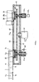
- FIG. 3 shows in top view and simplified a today preferred vacuum treatment apparatus according to the invention, wherein the transport arrangement 100 in cooperation with a vacuum treatment recipient 10 as shown in fig. 1 are exploited.
- Fig. 4 shows a cross-sectional representation along line IV - IV of fig. 3 , without handler 20.
- a transport arrangement 30 which is swivelable about a central axis A 30 .
- the transport arrangement 30 is driven for its swivel movement by a drive 32 with a control input C 32 .
- the transport arrangement 30 carries along its periphery six substrate carriers 34 for substrates 36.
- the vacuum treatment recipient 10 there are provided six stations, five of which, 38a to 38e, being surface treatment stations for the substrates 36, one thereof being the bi-directional load lock station 35 in analogy to load lock 5 of fig. 1 .
- the surface treatment stations 38a to 38e may all be realized for different substrate processings or a number of these treatments stations may be conceived for equal surface processing and even all of these stations may be conceived for equal substrate surface processing.
- Such treatment stations may be stations for PVD surface treatment, e.g. sputtering stations for reactive or non-reactive sputtering, thereby especially magnetron sputtering, may be stations for arc evaporation coating, again reactive or non-reactive, may further be treatment stations for CVD, thereby especially for plasma-enhanced CVD, may further be etching stations, heating or cooling stations, etc.
- the respective substrate carriers 34 reside within inner valve members, one thereof, 40 c , being shown in fig. 4 .
- inner valve members one thereof, 40 c , being shown in fig. 4 .
- cylinder/piston arrangements mounted to the bottom wall 42 of the vacuum treatment recipient 10, cylinder/piston arrangements, respectively 44 a to 44 e and 44 35 .
- the substrate carriers 34 and the valve members 40 may be lifted and retracted independently.
- the substrate carrier 34 may be lifted into treatment position for substrate 36 within treatment station 38 c .
- the processing space within the treatment station 38 c is sealed from the remaining interior i of the vacuum treatment recipient 10 by means of lifting the valve member 40 c towards and onto wall 48 of the vacuum treatment recipient 10.
- a controlled rotary drive 46 c by means of which, once the respective substrate carrier 34 is brought into registering position with a treatment station 38, the substrate carrier 34 is rotated in its treatment position e.g. to establish uniform treatment along the surface of the substrate.
- the transport arrangement 30 is stepwise rotated by respective angular steps ⁇ as shown in fig. 3 so that after each angular swiveling step one of the valve member 40 and substrate carriers 34 is in registering position with one of the treatment stations 38 and load lock 35. Then in the registering positions, seal-off of the treatment or processing atmosphere from the inside i of the vacuum treatment recipient 10 is established by lifting the valve member 40 towards and onto the inner surface of the top wall 48 of the vacuum treatment recipient 10, thereby the substrate carriers 34 are lifted in respective processing positions within the treatment stations 38. Lifting of the substrate carriers 34 on one hand and of valve members 40 on the other hand is performed substantially simultaneously at each of the treatment stations.
- That valve member 40 which registers with the load lock 35 acts as the inside load lock valve.
- the substrate handler 1 with swiveling drive 9 is conceived as was explained in context with fig. 1 .
- the drives 11 a and 11 b as shown in fig. 1 are realized by respective cylinder/piston drives 11 a' and 11 b' .
- a load lock vacuum pump 48 is operationally connected to the load lock compartment of the load lock 35.
- the second substrate handler 20 is conceived as was exemplified more schematically in the figures 1 to 2f .
- step forwards movement of the transport arrangement 30 and occurrence of 180° swiveling steps of the first substrate handler 1 are in synchronism, but phase shifted by half a step repetition period.
- the step control clock for the transport arrangement 30 which depends from the respective processing durations at the treatment stations 38, governs the swiveling clock for handler 1.
- an equal duration is established which accords with the duration which is necessitated to remove a treated substrate from the transport arrangement 30 onto one of the substrate carriers 1a or 1b of first substrate handler 1 and additionally to apply from the respective substrate carrier 1b or 1a of handler 1 a yet untreated substrate via the load lock 35 to the substrate transport arrangement 30.
- a third substrate handler 50 in a specific embodiment of the apparatus according to the invention.
- This third substrate handler 50 again with an eye on figures 2b to 2f , operates as source and destination location 7.
- the handler 50 is operated at the same step-controlling clock as the first substrate handler 1.
- Third substrate handler 50 thus removes from a respective one of the substrate carriers 20 a treated substrate and applies to the same an untreated substrate.
- the third substrate handler 50 is swiveled about an axis A 50 , preferably arranged parallel to the axes A 1 , A 20 , A 30 and is conceived as a two-arm handler in analogy to the substrate handler 1.
- the controlled swiveling drive for the third substrate handler 50 is addressed by reference number 52 in fig. 3 with control input C 52 .
- a one-directional conveyor arrangement 54 with inline substrate support areas 56 is provided.
- the one-directional conveyor 54 is stepwise moved forwards as shown by the arrow v, so that whenever a substrate carrier 50a or 50b of the third substrate handler 50 registers with one of the substrate carriers 20a to 20c of the second substrate handler 20, the other one of the two substrate carriers 50a, 50b registers with one of the substrate supports 56 upon the conveyor 54.
- an untreated substrate arriving from E in on a substrate support 56 is gripped by one of the substrate carriers 50a or 50b and subsequently, after a 180° swiveling step of the third substrate handler 50, a treated substrate is released and placed on the substrate support 56 which has just been freed.
- the treated substrate is moved in synchronism with transport arrangement 30.
- the substrate carriers 50a and 50b of the third substrate handler 50 are equipped with substrate gripping members as at these substrate carriers the substrates are to be held in suspended position.
- the apparatus as shown especially in fig. 3 possibly with different types of third substrate handler 50 as will be addressed later, allows utmost flexible conception for more complex substrate treatment apparatus.
- first apparatus 60a according to the embodiment of fig. 3 is provided along the one-directional conveyor 54.
- the front surface of the substrates is treated by five equal or different processing or treatment steps.
- the substrates are re-deposited by the third substrate handler 50 on the conveyor 54 they are stepwise moved forwards towards a flip station 58.
- the substrates are flipped so that their yet untreated surface is pointing upwards.
- the flipped-over substrates are then transported to a second apparatus 60b conceived as was explained in context with fig. 3 . There the backside of the substrates is treated.
- backside treatment may e.g. necessitate only one surface treatment or processing step at the apparatus 60b and as shown by respective hatching, only one of the treatment stations is operative or only one of such treatment stations is at all mounted.
- the substrates with surface treated backside are re-deposited upon the conveyor 54, so that downstream apparatus 60b substrates are stepwise transported which are treated on both, front surface and back surface.
- fig. 5 shows a further example of flexibly combining apparatus according to the present invention to more complex multi-apparatus arrangements.
- parallel processing of substrates is established, which leads to doubling the throughput at the output end E out of conveyor 54.
- every second workpiece support 56 of conveyor 54 is emptied from an untreated substrate, and a treated substrate is re-applied to the yet emptied workpiece support 56.
- the conveyor 54 is stepwise advanced by an extent according to two subsequent substrate supports 56, each time an untreated substrate has been replaced by a substrate having been treated in apparatus 60 c .
- a second apparatus 60 d identical to apparatus 60 c is provided along the conveyor 54. The spacing of the two apparatus 60 c and 60 d is established so that the second apparatus 60 d with its third substrate handler 50 d registers with an untreated substrate on the conveyor 54 when the first apparatus 60 c with its third substrate handler 50 c registers as well with an untreated substrate on the conveyor 54.
- the apparatus 60 d is thus loaded in parallel to the apparatus 60 c with an untreated substrate from the substrate carrier 54 and respectively re-applies a treated substrate back to the just freed substrate support 56 simultaneously with apparatus 60 c doing so.
- the conveyor 54 is advanced at double speed the output of treated substrates at E out is doubled due to the addressed parallel processing.
- substrate handling is performed in a cassette-to-cassette technique.
- a cassette-transport conveyor 54a wherein instead of single wafer supports 56 cassette or magazine supports 56a are provided.
- Full cassettes with untreated substrates are fed in arrow direction stepwise towards unload position P ul .
- the cassette with untreated substrates is unloaded by means of a pivot robot 58 onto the second substrate handler 20 and treated substrates are unloaded from the second substrate handler 20 and loaded in a next upstream cassette by handler 58.
- Stepwise forwards movement of the conveyor 54a is only performed after that a cassette with untreated substrates is emptied and, accordingly, the next upstream cassette is full with the respective number of treated substrates.
- cassette-to-cassette handling might also be performed with an eye e.g. on fig. 3 by means of a two-armed handler 50, thereby moving the conveyor 54a with cassettes forth and back to subsequently empty one cassette with untreated substrates and filling the upstream neighboring cassette with treated substrates.
- the apparatus according to the present invention is especially tailored today to treat substrates as silicon wafers for solar cell production. Thereby and with an eye e.g. on fig. 5 for depositing a layer which has triple thickness of subsequent layers, three subsequent treating stations are operated equally and such triple thickness layer is deposited in fact by subsequently depositing one third of the layer in three equally operated subsequent treating stations.
- substrate surface treatment may be performed highly flexibly, whereby all the treatment steps are subdivided in sub-processes of equal time duration.
- the addressed apparatus has a minimum footprint at optimized throughput. It has to be noted that all handling facilities are easily accessible from outside the vacuum treatment recipient, obviously with the exception of the transport arrangement 30 within such recipient. Substrates e.g.
- a thick layer of SiN:H may be deposited on silicon wafers by performing six times the equal layer deposition, e.g. by plasma-enhanced CVD or reactive PVD (sputtering).
- a relatively thin layer of SiN:H is deposited and upon such relatively thin layer a further layer of SiN with approximately five times the thickness of the SiN:H layer.
- a relatively thin layer of SiN:H is deposited, then due to higher deposition rate, a relatively thick layer of ZnS-SiO 2 followed by a relatively thick layer of SiO 2 in 4 substeps.
- Subdividing single unitary processing steps into substeps being performed subsequently at subsequent treatment stations is clearly performed taking into consideration the respective treatment rate of the addressed processes upon the substrate surface.
Landscapes
- Container, Conveyance, Adherence, Positioning, Of Wafer (AREA)
- Engineering & Computer Science (AREA)
- Robotics (AREA)
- Physical Vapour Deposition (AREA)
Claims (13)
- Appareil de traitement sous vide, comprenant• un récipient de traitement sous vide (10) comprenant un sas de chargement (5) entre l'intérieur (i) du récipient (10) et l'extérieur (e) du récipient (10), le sas de chargement (5) comprenant un dispositif à valve externe (1a, 1b) entre un compartiment du sas de chargement et l'extérieur (e), et un dispositif à valve interne entre le compartiment et le reste de l'intérieur (i), le sas de chargement (5) étant conçu comme un sas de chargement bidirectionnel pour le transfert de substrats entre l'intérieur (i) et l'extérieur (e);• un dispositif de transport (100) à l'extérieur (e), pour le transport bidirectionnel de substrats en direction et à partir du sas de chargement (5), et comprenant:- un premier manipulateur de substrats (1) qui est apte à pivoter sur un premier axe (A1) à l'aide d'un premier entraînement commandé (9) et qui comprend au moins deux premiers porte-substrats (1a, 1b) placés à égale distance du premier axe (A1);- un deuxième manipulateur de substrats (20) qui est apte à pivoter sur un deuxième axe (A2) à l'aide d'un deuxième entraînement commandé (21) et qui comprend au moins quatre deuxièmes porte-substrats (20a, 20b, 20c, 20d)) placés à égale distance du deuxième axe (A20);- les premiers et deuxièmes porte-substrats étant mutuellement alignés respectivement dans une position (P1/20) de leurs trajectoires de pivotement respectives, quand l'un desdits premiers porte-substrats est aligné avec l'un des deuxièmes porte-substrats l'autre premier porte-substrat est aligné avec le sas de chargement (5);- les premiers porte-substrats (1a, 1b) étant mobiles en direction et à partir du récipient de traitement sous vide (10) une fois qu'ils sont alignés avec le sas de chargement (5) grâce à des troisièmes entraînements commandés respectifs (11a, 11b), formant ainsi respectivement la valve externe.
- Appareil de traitement sous vide selon la revendication 1, étant précisé que le sas de chargement (5, 35) a une ouverture de passage vers l'extérieur qui est située dans une partie de paroi latérale supérieure du récipient de traitement sous vide (10).
- Appareil de l'une des revendications 1 ou 2, étant précisé que le premier manipulateur de substrats (1) comprend deux desdits premiers porte-substrats (1a, 1b) situés au niveau dudit premier manipulateur de substrats à l'opposé l'un de l'autre par rapport au premier axe (A1).
- Appareil selon l'une des revendications 1 à 3, étant précisé que le deuxième manipulateur de substrats comprend quatre des deuxièmes porte-substrats (20a, 20b, 20c, 20d) disposés par paires à l'opposé l'un de l'autre par rapport au deuxième axe (A20).
- Appareil de l'une des revendications 1 à 4, étant précisé que les premier et deuxième axes et le sens de mobilité des premiers porte-substrats en direction et à partir du récipient de traitement sous vide sont parallèles.
- Appareil de traitement selon l'une des revendications 1 à 5, étant précisé que le récipient de traitement sous vide comprend au moins deux emplacements de montage pour une station de traitement, pour traiter chacun un seul substrat, le récipient de traitement sous vide comprenant par ailleurs un autre dispositif de transport (30) qui est apte à pivoter sur un troisième axe (A30) à l'aide d'un troisième entraînement commandé, cet autre dispositif de transport (30) comprenant au moins trois supports de substrats (34) situés à égale distance du troisième axe et répartis uniformément dans le sens azimutal par rapport au troisième axe, et que l'unité de synchronisation commande de manière synchronisée le troisième entraînement.
- Appareil de traitement de la revendication 6, étant précisé que le troisième axe est parallèle au premier axe.
- Appareil de l'une des revendications 1 à 7, comprenant par ailleurs un convoyeur unidirectionnel (54) en interaction, pour le transport de substrats, avec le deuxième manipulateur de substrats (20).
- Appareil de la revendication 8, étant précisé que l'interaction entre le convoyeur unidirectionnel (54) et le deuxième manipulateur de substrats (20) se fait grâce à un troisième manipulateur de substrats.
- Appareil de traitement sous vide élargi comprenant au moins deux desdits appareils de traitement sous vide selon l'une des revendications 8 ou 9 le long du convoyeur unidirectionnel.
- Appareil de traitement sous vide élargi de la revendication 10, comprenant une station de basculement entre deux desdits appareils de traitement sous vide disposés le long du convoyeur unidirectionnel, pour retourner les substrats sur ledit convoyeur unidirectionnel.
- Utilisation de l'appareil de traitement sous vide selon l'une des revendications 1 à 9 ou de l'appareil de traitement sous vide élargi selon l'une des revendications 10 ou 11 pour traiter des substrats d'au moins 200 mm x 200 mm.
- Utilisation de l'appareil selon l'une des revendications 1 à 9 ou de l'appareil élargi selon l'une des revendications 10 ou 11 pour fabriquer des cellules solaires.
Priority Applications (1)
| Application Number | Priority Date | Filing Date | Title |
|---|---|---|---|
| PL10714592T PL2409317T3 (pl) | 2009-03-18 | 2010-03-11 | Urządzenie do obróbki próżniowej |
Applications Claiming Priority (2)
| Application Number | Priority Date | Filing Date | Title |
|---|---|---|---|
| US16108409P | 2009-03-18 | 2009-03-18 | |
| PCT/EP2010/053140 WO2010105967A2 (fr) | 2009-03-18 | 2010-03-11 | Appareil de traitement à vide |
Publications (3)
| Publication Number | Publication Date |
|---|---|
| EP2409317A2 EP2409317A2 (fr) | 2012-01-25 |
| EP2409317B1 true EP2409317B1 (fr) | 2013-12-11 |
| EP2409317B8 EP2409317B8 (fr) | 2014-02-19 |
Family
ID=42740047
Family Applications (1)
| Application Number | Title | Priority Date | Filing Date |
|---|---|---|---|
| EP10714592.2A Active EP2409317B8 (fr) | 2009-03-18 | 2010-03-11 | Appareil de traitement à vide |
Country Status (9)
| Country | Link |
|---|---|
| US (1) | US8870513B2 (fr) |
| EP (1) | EP2409317B8 (fr) |
| KR (4) | KR102027108B1 (fr) |
| CN (1) | CN102356459B (fr) |
| ES (1) | ES2450118T3 (fr) |
| MY (1) | MY157637A (fr) |
| PL (1) | PL2409317T3 (fr) |
| TW (1) | TWI553765B (fr) |
| WO (1) | WO2010105967A2 (fr) |
Cited By (1)
| Publication number | Priority date | Publication date | Assignee | Title |
|---|---|---|---|---|
| WO2019076553A1 (fr) | 2017-10-19 | 2019-04-25 | Evatec Ag | Procédé et appareil de traitement d'un substrat |
Families Citing this family (22)
| Publication number | Priority date | Publication date | Assignee | Title |
|---|---|---|---|---|
| US8210761B2 (en) * | 2008-06-26 | 2012-07-03 | Elc Management Llc | Cosmetic package with integrally molded wiper |
| KR102027108B1 (ko) * | 2009-03-18 | 2019-10-01 | 에바텍 아크티엔게젤샤프트 | 진공처리 장치 |
| GB0912385D0 (en) | 2009-07-16 | 2009-08-26 | Syngenta Ltd | Novel herbicides |
| EP2659506B1 (fr) | 2010-12-29 | 2021-08-25 | Evatec AG | Appareil de traitement sous vide et procédé de fabrication |
| TW201327712A (zh) * | 2011-11-01 | 2013-07-01 | 因特瓦克公司 | 以電漿處理太陽能電池晶圓之系統架構 |
| EP3069189A1 (fr) | 2013-11-14 | 2016-09-21 | Oerlikon Advanced Technologies AG | Appareil et procédé de recuit de revêtements anti-empreintes |
| CN105917019A (zh) * | 2014-02-04 | 2016-08-31 | 应用材料公司 | 用于有机材料的蒸发源、具有用于有机材料的蒸发源的设备、具有带有用于有机材料的蒸发源的蒸发沉积设备的系统以及用于操作用于有机材料的蒸发源的方法 |
| US9502275B1 (en) * | 2015-10-20 | 2016-11-22 | Lam Research Corporation | Service tunnel for use on capital equipment in semiconductor manufacturing and research fabs |
| CN109804309B (zh) * | 2016-07-29 | 2022-09-02 | 分子印记公司 | 微光刻中的基板加载 |
| KR102263614B1 (ko) | 2016-11-03 | 2021-06-09 | 몰레큘러 임프린츠 인코퍼레이티드 | 기판 로딩 시스템 |
| KR20200037824A (ko) | 2017-07-27 | 2020-04-09 | 에바텍 아크티엔게젤샤프트 | 투과 장벽 |
| US10998209B2 (en) | 2019-05-31 | 2021-05-04 | Applied Materials, Inc. | Substrate processing platforms including multiple processing chambers |
| US11249338B2 (en) * | 2019-07-08 | 2022-02-15 | Rockwell Collins, Inc. | Flexible to rigid integrated laminator |
| KR20230028761A (ko) | 2020-06-17 | 2023-03-02 | 에바텍 아크티엔게젤샤프트 | 진공 처리 장치 |
| US12080571B2 (en) | 2020-07-08 | 2024-09-03 | Applied Materials, Inc. | Substrate processing module and method of moving a workpiece |
| US11749542B2 (en) | 2020-07-27 | 2023-09-05 | Applied Materials, Inc. | Apparatus, system, and method for non-contact temperature monitoring of substrate supports |
| US11817331B2 (en) | 2020-07-27 | 2023-11-14 | Applied Materials, Inc. | Substrate holder replacement with protective disk during pasting process |
| US11600507B2 (en) | 2020-09-09 | 2023-03-07 | Applied Materials, Inc. | Pedestal assembly for a substrate processing chamber |
| US11610799B2 (en) | 2020-09-18 | 2023-03-21 | Applied Materials, Inc. | Electrostatic chuck having a heating and chucking capabilities |
| US12195314B2 (en) | 2021-02-02 | 2025-01-14 | Applied Materials, Inc. | Cathode exchange mechanism to improve preventative maintenance time for cluster system |
| US11674227B2 (en) | 2021-02-03 | 2023-06-13 | Applied Materials, Inc. | Symmetric pump down mini-volume with laminar flow cavity gas injection for high and low pressure |
| US12002668B2 (en) | 2021-06-25 | 2024-06-04 | Applied Materials, Inc. | Thermal management hardware for uniform temperature control for enhanced bake-out for cluster tool |
Family Cites Families (34)
| Publication number | Priority date | Publication date | Assignee | Title |
|---|---|---|---|---|
| US1281579A (en) * | 1917-01-18 | 1918-10-15 | William H Johnson | Tributary-feeder control. |
| US1846009A (en) * | 1928-02-17 | 1932-02-16 | White Cap Co | Apparatus for handling receptacles |
| US2888131A (en) * | 1954-07-27 | 1959-05-26 | Owens Illinois Glass Co | Article transfer mechanism |
| US3563170A (en) * | 1968-04-16 | 1971-02-16 | Reynolds Metals Co | Machine for marking the exterior cylindrical surfaces of cans in a continous nonidexing manner |
| US3712450A (en) * | 1970-12-18 | 1973-01-23 | Ball Corp | Method for handling articles |
| CH573985A5 (fr) * | 1973-11-22 | 1976-03-31 | Balzers Patent Beteilig Ag | |
| DE3827343A1 (de) * | 1988-08-12 | 1990-02-15 | Leybold Ag | Vorrichtung nach dem karussel-prinzip zum beschichten von substraten |
| FR2644567A1 (fr) * | 1989-03-17 | 1990-09-21 | Etudes Const Mecaniques | Dispositif pour l'execution de traitements thermiques enchaines en continu sous vide |
| FR2648119B1 (fr) * | 1989-06-09 | 1991-09-27 | Girondine Sa | Dispositif de transport de recipients, tels que des bouteilles |
| JP2884753B2 (ja) * | 1990-09-25 | 1999-04-19 | 日新電機株式会社 | イオン処理装置 |
| JPH04298060A (ja) * | 1991-03-26 | 1992-10-21 | Tokyo Electron Ltd | ウエハの位置合わせ装置 |
| DE4127341C2 (de) * | 1991-08-19 | 2000-03-09 | Leybold Ag | Vorrichtung zum selbsttätigen Gießen, Beschichten, Lackieren, Prüfen und Sortieren von Werkstücken |
| CH691377A5 (de) * | 1992-10-06 | 2001-07-13 | Unaxis Balzers Ag | Kammeranordnung für den Transport von Werkstücken und deren Verwendung. |
| DE4340522A1 (de) * | 1993-11-29 | 1995-06-01 | Leybold Ag | Vorrichtung und Verfahren zum schrittweisen und automatischen Be- und Entladen einer Beschichtungsanlage |
| DE19514037C2 (de) | 1995-04-13 | 1997-09-04 | Leybold Ag | Transportvorrichtung |
| JP3354761B2 (ja) * | 1995-08-30 | 2002-12-09 | オリジン電気株式会社 | ディスク用被膜形成装置 |
| US6702540B2 (en) | 1995-11-27 | 2004-03-09 | M2 Engineering Ab | Machine and method for manufacturing compact discs |
| US5863170A (en) * | 1996-04-16 | 1999-01-26 | Gasonics International | Modular process system |
| US6082950A (en) * | 1996-11-18 | 2000-07-04 | Applied Materials, Inc. | Front end wafer staging with wafer cassette turntables and on-the-fly wafer center finding |
| WO1999028951A2 (fr) * | 1997-11-28 | 1999-06-10 | Mattson Technology, Inc. | Systemes et procedes permettant de manutentionner des pieces devant subir un traitement sous vide, avec un debit eleve et une faible contamination |
| TW444275B (en) * | 1998-01-13 | 2001-07-01 | Toshiba Corp | Processing device, laser annealing device, laser annealing method, manufacturing device and substrate manufacturing device for panel display |
| DE19835154A1 (de) * | 1998-08-04 | 2000-02-10 | Leybold Systems Gmbh | Vorrichtung zur Beschichtung von Substraten in einer Vakuumkammer |
| US6244811B1 (en) * | 1999-06-29 | 2001-06-12 | Lam Research Corporation | Atmospheric wafer transfer module with nest for wafer transport robot |
| US7066703B2 (en) * | 1999-09-29 | 2006-06-27 | Tokyo Electron Limited | Chuck transport method and system |
| JP2008013851A (ja) * | 2000-04-27 | 2008-01-24 | Ebara Corp | 回転保持装置及び半導体基板処理装置 |
| EP1319243A2 (fr) * | 2000-09-15 | 2003-06-18 | Applied Materials, Inc. | Sas double a deux fentes pour equipement de procede |
| US7010388B2 (en) | 2003-05-22 | 2006-03-07 | Axcelis Technologies, Inc. | Work-piece treatment system having load lock and buffer |
| US7207766B2 (en) * | 2003-10-20 | 2007-04-24 | Applied Materials, Inc. | Load lock chamber for large area substrate processing system |
| DE602005006160T2 (de) * | 2004-12-23 | 2009-07-02 | CROWN Packaging Technology, Inc, Alsip | Handhabungseinrichtung für mehrstufigen prozess |
| TWI476855B (zh) | 2006-05-03 | 2015-03-11 | 吉恩股份有限公司 | 基板傳輸設備、和使用該設備的高速基板處理系統 |
| KR100818044B1 (ko) * | 2006-05-04 | 2008-03-31 | 위순임 | 기판 지지대와 기판 반송 장치 및 이를 이용한 기판 처리시스템 |
| US20080075563A1 (en) * | 2006-09-27 | 2008-03-27 | Mclane James R | Substrate handling system and method |
| JP2008153353A (ja) * | 2006-12-15 | 2008-07-03 | Olympus Corp | 基板搬送装置及び基板検査装置 |
| KR102027108B1 (ko) * | 2009-03-18 | 2019-10-01 | 에바텍 아크티엔게젤샤프트 | 진공처리 장치 |
-
2010
- 2010-03-11 KR KR1020167032429A patent/KR102027108B1/ko active Active
- 2010-03-11 ES ES10714592.2T patent/ES2450118T3/es active Active
- 2010-03-11 PL PL10714592T patent/PL2409317T3/pl unknown
- 2010-03-11 MY MYPI2011004398A patent/MY157637A/en unknown
- 2010-03-11 US US13/257,001 patent/US8870513B2/en active Active
- 2010-03-11 CN CN201080012308.8A patent/CN102356459B/zh active Active
- 2010-03-11 KR KR1020197027996A patent/KR102103477B1/ko active Active
- 2010-03-11 KR KR1020207011015A patent/KR102298893B1/ko active Active
- 2010-03-11 WO PCT/EP2010/053140 patent/WO2010105967A2/fr not_active Ceased
- 2010-03-11 EP EP10714592.2A patent/EP2409317B8/fr active Active
- 2010-03-11 KR KR1020117024531A patent/KR101680295B1/ko active Active
- 2010-03-16 TW TW099107570A patent/TWI553765B/zh active
Cited By (1)
| Publication number | Priority date | Publication date | Assignee | Title |
|---|---|---|---|---|
| WO2019076553A1 (fr) | 2017-10-19 | 2019-04-25 | Evatec Ag | Procédé et appareil de traitement d'un substrat |
Also Published As
| Publication number | Publication date |
|---|---|
| WO2010105967A2 (fr) | 2010-09-23 |
| ES2450118T3 (es) | 2014-03-24 |
| EP2409317B8 (fr) | 2014-02-19 |
| EP2409317A2 (fr) | 2012-01-25 |
| KR102103477B1 (ko) | 2020-06-01 |
| CN102356459B (zh) | 2014-05-14 |
| TWI553765B (zh) | 2016-10-11 |
| TW201113972A (en) | 2011-04-16 |
| US8870513B2 (en) | 2014-10-28 |
| KR20110128943A (ko) | 2011-11-30 |
| PL2409317T3 (pl) | 2014-06-30 |
| MY157637A (en) | 2016-07-15 |
| KR101680295B1 (ko) | 2016-11-29 |
| KR20200044131A (ko) | 2020-04-28 |
| KR102027108B1 (ko) | 2019-10-01 |
| KR20190111164A (ko) | 2019-10-01 |
| WO2010105967A3 (fr) | 2011-05-26 |
| KR20160137660A (ko) | 2016-11-30 |
| US20120003064A1 (en) | 2012-01-05 |
| KR102298893B1 (ko) | 2021-09-08 |
| CN102356459A (zh) | 2012-02-15 |
Similar Documents
| Publication | Publication Date | Title |
|---|---|---|
| EP2409317B1 (fr) | Appareil de traitement à vide | |
| EP2207909B1 (fr) | Procédé de fabrication de pièces et appareil | |
| US10752987B2 (en) | System architecture for combined static and pass-by processing | |
| EP0690480B1 (fr) | Mouvement de pièces à haute vitesse pour traitement sous vide | |
| US8367565B2 (en) | Methods and systems of transferring, docking and processing substrates | |
| JPS6130030B2 (fr) | ||
| JPH09176857A (ja) | ワークピースを表面処理するための真空装置 | |
| EP3108030A1 (fr) | Système et procédé pour le traitement bifacial de substrats | |
| KR20190053293A (ko) | 코팅 장치 및 방법 | |
| KR20080082905A (ko) | 기판처리장치 | |
| US6177129B1 (en) | Process for handling workpieces and apparatus therefor | |
| US20010051081A1 (en) | Processes for vacuum treating workpieces, and corresponding process equipment | |
| EP3864691A1 (fr) | Appareil de traitement sous vide et procédé de traitement de substrats sous vide | |
| CN222524651U (zh) | 一种连续真空蒸镀设备 | |
| CN116888722A (zh) | 真空处理设备和用于制造真空处理衬底的方法 | |
| KR20080039566A (ko) | 웨이퍼 전달모듈 및 이를 구비한 박막 증착 시스템 |
Legal Events
| Date | Code | Title | Description |
|---|---|---|---|
| PUAI | Public reference made under article 153(3) epc to a published international application that has entered the european phase |
Free format text: ORIGINAL CODE: 0009012 |
|
| 17P | Request for examination filed |
Effective date: 20110817 |
|
| AK | Designated contracting states |
Kind code of ref document: A2 Designated state(s): AT BE BG CH CY CZ DE DK EE ES FI FR GB GR HR HU IE IS IT LI LT LU LV MC MK MT NL NO PL PT RO SE SI SK SM TR |
|
| DAX | Request for extension of the european patent (deleted) | ||
| REG | Reference to a national code |
Ref country code: DE Ref legal event code: R079 Ref document number: 602010012339 Country of ref document: DE Free format text: PREVIOUS MAIN CLASS: H01L0021000000 Ipc: H01L0021670000 |
|
| RIC1 | Information provided on ipc code assigned before grant |
Ipc: H01L 21/67 20060101AFI20120712BHEP Ipc: H01L 21/677 20060101ALI20120712BHEP |
|
| GRAP | Despatch of communication of intention to grant a patent |
Free format text: ORIGINAL CODE: EPIDOSNIGR1 |
|
| INTG | Intention to grant announced |
Effective date: 20130729 |
|
| GRAS | Grant fee paid |
Free format text: ORIGINAL CODE: EPIDOSNIGR3 |
|
| GRAA | (expected) grant |
Free format text: ORIGINAL CODE: 0009210 |
|
| AK | Designated contracting states |
Kind code of ref document: B1 Designated state(s): AT BE BG CH CY CZ DE DK EE ES FI FR GB GR HR HU IE IS IT LI LT LU LV MC MK MT NL NO PL PT RO SE SI SK SM TR |
|
| REG | Reference to a national code |
Ref country code: GB Ref legal event code: FG4D |
|
| REG | Reference to a national code |
Ref country code: CH Ref legal event code: EP |
|
| RAP2 | Party data changed (patent owner data changed or rights of a patent transferred) |
Owner name: OERLIKON ADVANCED TECHNOLOGIES AG |
|
| REG | Reference to a national code |
Ref country code: AT Ref legal event code: REF Ref document number: 644972 Country of ref document: AT Kind code of ref document: T Effective date: 20140115 |
|
| REG | Reference to a national code |
Ref country code: IE Ref legal event code: FG4D |
|
| REG | Reference to a national code |
Ref country code: DE Ref legal event code: R096 Ref document number: 602010012339 Country of ref document: DE Effective date: 20140206 |
|
| REG | Reference to a national code |
Ref country code: ES Ref legal event code: FG2A Ref document number: 2450118 Country of ref document: ES Kind code of ref document: T3 Effective date: 20140324 |
|
| REG | Reference to a national code |
Ref country code: NL Ref legal event code: VDEP Effective date: 20131211 |
|
| PG25 | Lapsed in a contracting state [announced via postgrant information from national office to epo] |
Ref country code: SE Free format text: LAPSE BECAUSE OF FAILURE TO SUBMIT A TRANSLATION OF THE DESCRIPTION OR TO PAY THE FEE WITHIN THE PRESCRIBED TIME-LIMIT Effective date: 20131211 Ref country code: NL Free format text: LAPSE BECAUSE OF FAILURE TO SUBMIT A TRANSLATION OF THE DESCRIPTION OR TO PAY THE FEE WITHIN THE PRESCRIBED TIME-LIMIT Effective date: 20131211 Ref country code: HR Free format text: LAPSE BECAUSE OF FAILURE TO SUBMIT A TRANSLATION OF THE DESCRIPTION OR TO PAY THE FEE WITHIN THE PRESCRIBED TIME-LIMIT Effective date: 20131211 Ref country code: NO Free format text: LAPSE BECAUSE OF FAILURE TO SUBMIT A TRANSLATION OF THE DESCRIPTION OR TO PAY THE FEE WITHIN THE PRESCRIBED TIME-LIMIT Effective date: 20140311 Ref country code: LT Free format text: LAPSE BECAUSE OF FAILURE TO SUBMIT A TRANSLATION OF THE DESCRIPTION OR TO PAY THE FEE WITHIN THE PRESCRIBED TIME-LIMIT Effective date: 20131211 Ref country code: FI Free format text: LAPSE BECAUSE OF FAILURE TO SUBMIT A TRANSLATION OF THE DESCRIPTION OR TO PAY THE FEE WITHIN THE PRESCRIBED TIME-LIMIT Effective date: 20131211 |
|
| REG | Reference to a national code |
Ref country code: LT Ref legal event code: MG4D |
|
| PG25 | Lapsed in a contracting state [announced via postgrant information from national office to epo] |
Ref country code: CY Free format text: LAPSE BECAUSE OF FAILURE TO SUBMIT A TRANSLATION OF THE DESCRIPTION OR TO PAY THE FEE WITHIN THE PRESCRIBED TIME-LIMIT Effective date: 20131211 Ref country code: LV Free format text: LAPSE BECAUSE OF FAILURE TO SUBMIT A TRANSLATION OF THE DESCRIPTION OR TO PAY THE FEE WITHIN THE PRESCRIBED TIME-LIMIT Effective date: 20131211 |
|
| PGFP | Annual fee paid to national office [announced via postgrant information from national office to epo] |
Ref country code: IT Payment date: 20140310 Year of fee payment: 5 Ref country code: ES Payment date: 20140211 Year of fee payment: 5 |
|
| REG | Reference to a national code |
Ref country code: PL Ref legal event code: T3 |
|
| PG25 | Lapsed in a contracting state [announced via postgrant information from national office to epo] |
Ref country code: IS Free format text: LAPSE BECAUSE OF FAILURE TO SUBMIT A TRANSLATION OF THE DESCRIPTION OR TO PAY THE FEE WITHIN THE PRESCRIBED TIME-LIMIT Effective date: 20140411 Ref country code: BE Free format text: LAPSE BECAUSE OF FAILURE TO SUBMIT A TRANSLATION OF THE DESCRIPTION OR TO PAY THE FEE WITHIN THE PRESCRIBED TIME-LIMIT Effective date: 20131211 Ref country code: EE Free format text: LAPSE BECAUSE OF FAILURE TO SUBMIT A TRANSLATION OF THE DESCRIPTION OR TO PAY THE FEE WITHIN THE PRESCRIBED TIME-LIMIT Effective date: 20131211 |
|
| PG25 | Lapsed in a contracting state [announced via postgrant information from national office to epo] |
Ref country code: RO Free format text: LAPSE BECAUSE OF FAILURE TO SUBMIT A TRANSLATION OF THE DESCRIPTION OR TO PAY THE FEE WITHIN THE PRESCRIBED TIME-LIMIT Effective date: 20131211 Ref country code: PT Free format text: LAPSE BECAUSE OF FAILURE TO SUBMIT A TRANSLATION OF THE DESCRIPTION OR TO PAY THE FEE WITHIN THE PRESCRIBED TIME-LIMIT Effective date: 20140411 Ref country code: SK Free format text: LAPSE BECAUSE OF FAILURE TO SUBMIT A TRANSLATION OF THE DESCRIPTION OR TO PAY THE FEE WITHIN THE PRESCRIBED TIME-LIMIT Effective date: 20131211 |
|
| PGFP | Annual fee paid to national office [announced via postgrant information from national office to epo] |
Ref country code: CZ Payment date: 20140307 Year of fee payment: 5 Ref country code: CH Payment date: 20140623 Year of fee payment: 5 |
|
| REG | Reference to a national code |
Ref country code: DE Ref legal event code: R097 Ref document number: 602010012339 Country of ref document: DE |
|
| PGFP | Annual fee paid to national office [announced via postgrant information from national office to epo] |
Ref country code: PL Payment date: 20140121 Year of fee payment: 5 |
|
| PLBE | No opposition filed within time limit |
Free format text: ORIGINAL CODE: 0009261 |
|
| STAA | Information on the status of an ep patent application or granted ep patent |
Free format text: STATUS: NO OPPOSITION FILED WITHIN TIME LIMIT |
|
| PG25 | Lapsed in a contracting state [announced via postgrant information from national office to epo] |
Ref country code: LU Free format text: LAPSE BECAUSE OF FAILURE TO SUBMIT A TRANSLATION OF THE DESCRIPTION OR TO PAY THE FEE WITHIN THE PRESCRIBED TIME-LIMIT Effective date: 20140311 Ref country code: DK Free format text: LAPSE BECAUSE OF FAILURE TO SUBMIT A TRANSLATION OF THE DESCRIPTION OR TO PAY THE FEE WITHIN THE PRESCRIBED TIME-LIMIT Effective date: 20131211 |
|
| 26N | No opposition filed |
Effective date: 20140912 |
|
| REG | Reference to a national code |
Ref country code: DE Ref legal event code: R097 Ref document number: 602010012339 Country of ref document: DE Effective date: 20140912 |
|
| PG25 | Lapsed in a contracting state [announced via postgrant information from national office to epo] |
Ref country code: SI Free format text: LAPSE BECAUSE OF FAILURE TO SUBMIT A TRANSLATION OF THE DESCRIPTION OR TO PAY THE FEE WITHIN THE PRESCRIBED TIME-LIMIT Effective date: 20131211 |
|
| PG25 | Lapsed in a contracting state [announced via postgrant information from national office to epo] |
Ref country code: CZ Free format text: LAPSE BECAUSE OF NON-PAYMENT OF DUE FEES Effective date: 20150311 |
|
| REG | Reference to a national code |
Ref country code: CH Ref legal event code: PL |
|
| PG25 | Lapsed in a contracting state [announced via postgrant information from national office to epo] |
Ref country code: IT Free format text: LAPSE BECAUSE OF NON-PAYMENT OF DUE FEES Effective date: 20150311 |
|
| PG25 | Lapsed in a contracting state [announced via postgrant information from national office to epo] |
Ref country code: CH Free format text: LAPSE BECAUSE OF NON-PAYMENT OF DUE FEES Effective date: 20150331 Ref country code: LI Free format text: LAPSE BECAUSE OF NON-PAYMENT OF DUE FEES Effective date: 20150331 |
|
| REG | Reference to a national code |
Ref country code: FR Ref legal event code: PLFP Year of fee payment: 7 |
|
| PG25 | Lapsed in a contracting state [announced via postgrant information from national office to epo] |
Ref country code: MT Free format text: LAPSE BECAUSE OF FAILURE TO SUBMIT A TRANSLATION OF THE DESCRIPTION OR TO PAY THE FEE WITHIN THE PRESCRIBED TIME-LIMIT Effective date: 20131211 |
|
| REG | Reference to a national code |
Ref country code: ES Ref legal event code: FD2A Effective date: 20160427 |
|
| PG25 | Lapsed in a contracting state [announced via postgrant information from national office to epo] |
Ref country code: SM Free format text: LAPSE BECAUSE OF FAILURE TO SUBMIT A TRANSLATION OF THE DESCRIPTION OR TO PAY THE FEE WITHIN THE PRESCRIBED TIME-LIMIT Effective date: 20131211 |
|
| REG | Reference to a national code |
Ref country code: AT Ref legal event code: MM01 Ref document number: 644972 Country of ref document: AT Kind code of ref document: T Effective date: 20150311 |
|
| PG25 | Lapsed in a contracting state [announced via postgrant information from national office to epo] |
Ref country code: PL Free format text: LAPSE BECAUSE OF NON-PAYMENT OF DUE FEES Effective date: 20150311 Ref country code: MC Free format text: LAPSE BECAUSE OF FAILURE TO SUBMIT A TRANSLATION OF THE DESCRIPTION OR TO PAY THE FEE WITHIN THE PRESCRIBED TIME-LIMIT Effective date: 20131211 |
|
| PG25 | Lapsed in a contracting state [announced via postgrant information from national office to epo] |
Ref country code: BG Free format text: LAPSE BECAUSE OF FAILURE TO SUBMIT A TRANSLATION OF THE DESCRIPTION OR TO PAY THE FEE WITHIN THE PRESCRIBED TIME-LIMIT Effective date: 20131211 Ref country code: GR Free format text: LAPSE BECAUSE OF FAILURE TO SUBMIT A TRANSLATION OF THE DESCRIPTION OR TO PAY THE FEE WITHIN THE PRESCRIBED TIME-LIMIT Effective date: 20140312 |
|
| PG25 | Lapsed in a contracting state [announced via postgrant information from national office to epo] |
Ref country code: TR Free format text: LAPSE BECAUSE OF FAILURE TO SUBMIT A TRANSLATION OF THE DESCRIPTION OR TO PAY THE FEE WITHIN THE PRESCRIBED TIME-LIMIT Effective date: 20131211 Ref country code: ES Free format text: LAPSE BECAUSE OF NON-PAYMENT OF DUE FEES Effective date: 20150312 Ref country code: HU Free format text: LAPSE BECAUSE OF FAILURE TO SUBMIT A TRANSLATION OF THE DESCRIPTION OR TO PAY THE FEE WITHIN THE PRESCRIBED TIME-LIMIT; INVALID AB INITIO Effective date: 20100311 |
|
| PG25 | Lapsed in a contracting state [announced via postgrant information from national office to epo] |
Ref country code: AT Free format text: LAPSE BECAUSE OF NON-PAYMENT OF DUE FEES Effective date: 20150311 |
|
| REG | Reference to a national code |
Ref country code: FR Ref legal event code: PLFP Year of fee payment: 8 |
|
| REG | Reference to a national code |
Ref country code: FR Ref legal event code: PLFP Year of fee payment: 9 |
|
| PG25 | Lapsed in a contracting state [announced via postgrant information from national office to epo] |
Ref country code: MK Free format text: LAPSE BECAUSE OF FAILURE TO SUBMIT A TRANSLATION OF THE DESCRIPTION OR TO PAY THE FEE WITHIN THE PRESCRIBED TIME-LIMIT Effective date: 20131211 |
|
| REG | Reference to a national code |
Ref country code: DE Ref legal event code: R081 Ref document number: 602010012339 Country of ref document: DE Owner name: EVATEC AG, CH Free format text: FORMER OWNER: OERLIKON ADVANCED TECHNOLOGIES AG, BALZERS, LI |
|
| REG | Reference to a national code |
Ref country code: DE Ref legal event code: R081 Ref document number: 602010012339 Country of ref document: DE Owner name: EVATEC AG, CH Free format text: FORMER OWNER: EVATEC ADVANCED TECHNOLOGIES AG, BALZERS, LI |
|
| REG | Reference to a national code |
Ref country code: GB Ref legal event code: 732E Free format text: REGISTERED BETWEEN 20190321 AND 20190327 |
|
| PGFP | Annual fee paid to national office [announced via postgrant information from national office to epo] |
Ref country code: IE Payment date: 20200309 Year of fee payment: 11 |
|
| PGFP | Annual fee paid to national office [announced via postgrant information from national office to epo] |
Ref country code: FR Payment date: 20210210 Year of fee payment: 12 |
|
| PGFP | Annual fee paid to national office [announced via postgrant information from national office to epo] |
Ref country code: GB Payment date: 20210308 Year of fee payment: 12 |
|
| PG25 | Lapsed in a contracting state [announced via postgrant information from national office to epo] |
Ref country code: IE Free format text: LAPSE BECAUSE OF NON-PAYMENT OF DUE FEES Effective date: 20210311 |
|
| GBPC | Gb: european patent ceased through non-payment of renewal fee |
Effective date: 20220311 |
|
| PG25 | Lapsed in a contracting state [announced via postgrant information from national office to epo] |
Ref country code: GB Free format text: LAPSE BECAUSE OF NON-PAYMENT OF DUE FEES Effective date: 20220311 Ref country code: FR Free format text: LAPSE BECAUSE OF NON-PAYMENT OF DUE FEES Effective date: 20220331 |
|
| P01 | Opt-out of the competence of the unified patent court (upc) registered |
Effective date: 20230526 |
|
| REG | Reference to a national code |
Ref country code: DE Ref legal event code: R079 Ref document number: 602010012339 Country of ref document: DE Free format text: PREVIOUS MAIN CLASS: H01L0021670000 Ipc: H10P0072000000 |
|
| PGFP | Annual fee paid to national office [announced via postgrant information from national office to epo] |
Ref country code: DE Payment date: 20260304 Year of fee payment: 17 |