EP2409842B1 - Tintenstrahlaufzeichner - Google Patents
Tintenstrahlaufzeichner Download PDFInfo
- Publication number
- EP2409842B1 EP2409842B1 EP11185814.8A EP11185814A EP2409842B1 EP 2409842 B1 EP2409842 B1 EP 2409842B1 EP 11185814 A EP11185814 A EP 11185814A EP 2409842 B1 EP2409842 B1 EP 2409842B1
- Authority
- EP
- European Patent Office
- Prior art keywords
- dots
- recording device
- printing medium
- inkjet recording
- ink droplets
- Prior art date
- Legal status (The legal status is an assumption and is not a legal conclusion. Google has not performed a legal analysis and makes no representation as to the accuracy of the status listed.)
- Expired - Lifetime
Links
Images






Classifications
-
- B—PERFORMING OPERATIONS; TRANSPORTING
- B41—PRINTING; LINING MACHINES; TYPEWRITERS; STAMPS
- B41J—TYPEWRITERS; SELECTIVE PRINTING MECHANISMS, i.e. MECHANISMS PRINTING OTHERWISE THAN FROM A FORME; CORRECTION OF TYPOGRAPHICAL ERRORS
- B41J2/00—Typewriters or selective printing mechanisms characterised by the printing or marking process for which they are designed
- B41J2/005—Typewriters or selective printing mechanisms characterised by the printing or marking process for which they are designed characterised by bringing liquid or particles selectively into contact with a printing material
- B41J2/01—Ink jet
- B41J2/21—Ink jet for multi-colour printing
- B41J2/2132—Print quality control characterised by dot disposition, e.g. for reducing white stripes or banding
-
- B—PERFORMING OPERATIONS; TRANSPORTING
- B41—PRINTING; LINING MACHINES; TYPEWRITERS; STAMPS
- B41J—TYPEWRITERS; SELECTIVE PRINTING MECHANISMS, i.e. MECHANISMS PRINTING OTHERWISE THAN FROM A FORME; CORRECTION OF TYPOGRAPHICAL ERRORS
- B41J2/00—Typewriters or selective printing mechanisms characterised by the printing or marking process for which they are designed
- B41J2/005—Typewriters or selective printing mechanisms characterised by the printing or marking process for which they are designed characterised by bringing liquid or particles selectively into contact with a printing material
- B41J2/01—Ink jet
- B41J2/015—Ink jet characterised by the jet generation process
- B41J2/04—Ink jet characterised by the jet generation process generating single droplets or particles on demand
- B41J2/045—Ink jet characterised by the jet generation process generating single droplets or particles on demand by pressure, e.g. electromechanical transducers
- B41J2/04501—Control methods or devices therefor, e.g. driver circuits, control circuits
- B41J2/04581—Control methods or devices therefor, e.g. driver circuits, control circuits controlling heads based on piezoelectric elements
-
- B—PERFORMING OPERATIONS; TRANSPORTING
- B41—PRINTING; LINING MACHINES; TYPEWRITERS; STAMPS
- B41J—TYPEWRITERS; SELECTIVE PRINTING MECHANISMS, i.e. MECHANISMS PRINTING OTHERWISE THAN FROM A FORME; CORRECTION OF TYPOGRAPHICAL ERRORS
- B41J2/00—Typewriters or selective printing mechanisms characterised by the printing or marking process for which they are designed
- B41J2/005—Typewriters or selective printing mechanisms characterised by the printing or marking process for which they are designed characterised by bringing liquid or particles selectively into contact with a printing material
- B41J2/01—Ink jet
- B41J2/015—Ink jet characterised by the jet generation process
- B41J2/04—Ink jet characterised by the jet generation process generating single droplets or particles on demand
- B41J2/045—Ink jet characterised by the jet generation process generating single droplets or particles on demand by pressure, e.g. electromechanical transducers
- B41J2/04501—Control methods or devices therefor, e.g. driver circuits, control circuits
- B41J2/04593—Dot-size modulation by changing the size of the drop
-
- B—PERFORMING OPERATIONS; TRANSPORTING
- B41—PRINTING; LINING MACHINES; TYPEWRITERS; STAMPS
- B41J—TYPEWRITERS; SELECTIVE PRINTING MECHANISMS, i.e. MECHANISMS PRINTING OTHERWISE THAN FROM A FORME; CORRECTION OF TYPOGRAPHICAL ERRORS
- B41J2/00—Typewriters or selective printing mechanisms characterised by the printing or marking process for which they are designed
- B41J2/005—Typewriters or selective printing mechanisms characterised by the printing or marking process for which they are designed characterised by bringing liquid or particles selectively into contact with a printing material
- B41J2/01—Ink jet
- B41J2/21—Ink jet for multi-colour printing
- B41J2/2121—Ink jet for multi-colour printing characterised by dot size, e.g. combinations of printed dots of different diameter
- B41J2/2128—Ink jet for multi-colour printing characterised by dot size, e.g. combinations of printed dots of different diameter by means of energy modulation
Definitions
- the present invention relates to an inkjet recording device capable of, through a simple control process, forming high-quality images having no noticeable deviations in dot positions.
- Line-type inkjet recording devices well known in the art are equipped with a line head having nozzles arranged over the maximum printing width of a printing medium.
- the line head can remain fixed while the printing medium is conveyed a prescribed distance after the line head prints each line.
- this line-type inkjet recording device has the advantage of being able to print faster than serial-type inkjet printing devices that print while reciprocating a print head.
- Fig. 1(a) illustrates the ideal relationship between the nozzles and dots formed on the printing medium for the conventional line-type inkjet recording device.
- a line head 101 has five nozzles 102a-102e arranged linearly (in the left-to-right direction in Fig. 1 ) at a prescribed pitch P.
- the nozzles 102a-102e are actually not arranged along the same line but are each disposed in one of a plurality of lines in the line head.
- Fig. 1 shows the nozzles 102a-102e that eject ink droplets for forming dots within the same line as being themselves arranged in the same line.
- the nozzles 102a-102e eject ink droplets toward a printing medium (not shown) as the printing medium is conveyed in a conveying direction H (downward in Fig. 1 ) to a position opposite the line head 101.
- the ink droplets ejected from the nozzles 102a-102e impact the printing medium and form dots of a size sufficient to circumscribe square pixels (indicated by dotted lines in Fig. 1(a) ).
- ink droplets ejected from the nozzle 102a form a column of dots A arranged vertically in Fig. 1 .
- the nozzles 102b, 102c, 102d, and 102e produce columns of dots B, C, D, and E having no gaps therebetween.
- ink droplets are expected to follow a vertical trajectory toward the printing medium, ink droplets are sometimes ejected along a slanted trajectory relative to the printing medium due to various reasons, such as dust, solidified ink globules, and the like obstructing one of the nozzles 102a-102e or ink deposited around the periphery of the nozzle pulling against the ejected ink droplet.
- Fig. 1(b) shows the relationship between the nozzles and dots formed by ink droplets ejected from the nozzles when ink droplets ejected from the nozzle 102c follow a slanted trajectory relative to the printing medium due to one of the reasons described above.
- the ink droplets form a column of dots C having a bias toward the column of dots D so that a pitch D2 between the columns of dots B and C is greater than the prescribed pitch. Consequently, a gap is produced between the columns of dots B and C that appears as a streak along the conveying direction H of the printing medium, lowering the quality of the image.
- Patent Reference 1 discloses an inkjet printer comprising means for vibrating the line head 101 described above.
- ink droplets ejected from the nozzles also vibrate in response, decreasing the gap described above and thereby preventing a drop in image quality.
- Patent Reference 2 Another technique for resolving the problem described above is disclosed in Patent Reference 2 given below.
- a plurality of heaters capable of being driven independently of one another is provided for a single nozzle, the heaters being provided at different positions in an ink chamber corresponding to the nozzle.
- This technology changes the heater being driven and the driving force of the heater for each line.
- this technology can vary the positions at which the ink droplets impact the printing medium, thereby reducing the gap described above and preventing a drop in image quality.
- US 2004/0032438A1 discloses printing oversized dots in images to provide printer fault tolerance.
- D1 identifies localized errors on an image due to partial or total device failure and if possible, adjusts the size of ink dots in adjacent rows or columns so as to lessen the visual effect of the printing error at that location.
- D1 discloses an example with nozzles a-n which eject dots in rows 1-8 wherein the distance between the nozzles and the rows can be seen to be similar from all the figures ( Figures 1-5 ) of D1.
- Patent Reference 1 leads to a larger device and an increase in manufacturing costs.
- Patent Reference 2 increases the complexity and cost of the manufacturing process and requires a complex control process for individually controlling the heaters.
- the present invention provides an inkjet recording device, comprising nozzles arranged in a first direction within a printing area of a printing medium for ejecting ink droplets, and a line head in which the nozzles are formed, is configured to move relative to the printing medium in a second direction orthogonal to the first direction for forming an image on the printing medium, wherein the nozzles are arranged at a pitch (q) in the first direction smaller than a pitch (D) in the second direction of dots formed by ink droplets ejected from the nozzles impacting the printing medium, and characterized in that the device is configured such that an overlapped area of neighbouring dots in the first direction is larger than an overlapped area of dots in the second direction.
- the nozzles are arranged at a pitch in the first direction smaller than a pitch in the second direction of dots formed by ink droplets ejected from the nozzles impacting the printing medium. Accordingly, the inkjet recording device can produce dots in the first direction of a smaller pitch than the dots in the second direction.
- gaps are less likely to be formed between dots arranged in the first direction than in the method of setting the pitch for dots in the first direction identical to the pitch of dots in the second direction, even when some factor causes dots arranged in the first direction to shift in the first direction. Hence, it is possible to form high-quality images without noticeable gaps produced by deviations in dot positions.
- the inkjet recording device described above further comprises outputting means configured to output instructions to eject ink droplets from the nozzles toward the printing medium so as to impact the printing medium at prescribed positions for forming dots corresponding to print data; the outputting means outputting instructions to form more dots in the first direction than the number indicated in the print data based on the pitch of nozzles in the first direction that is smaller than the pitch of neighboring dots in the second direction.
- this configuration can set the ratio of the image size in the first direction and second direction approximately the same as when the pitch of dots is identical in the first and second directions, even when the pitch of dots arranged in the first direction is less than that of dots arranged in the second direction.
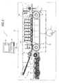
- FIG. 2 is a schematic diagram showing a personal computer 1 (hereinafter referred to as "PC 1") functioning as a controller for an inkjet recording device, which is one of the present inventions, and an inkjet printer 1A (hereinafter referred to as “printer 1A.”) connected to the PC 1 via a communication cable 40.
- PC 1 personal computer 1
- printer 1A inkjet printer 1A
- the PC 1 outputs instructions to the printer 1A through the communication cable 40 instructing the printer 1A to eject ink droplets through nozzles onto a printing medium so that the droplets that land on the printing medium are a prescribed size corresponding to print data.
- the PC 1 includes an LCD 42 for displaying an output image and the like, and a keyboard 43 for inputting a command to print out data on the printer 1A, for example.
- the controller for an inkjet recording device can also be implemented by a computational device other than the PC 1, such as a tablet PC or a PDA.
- the communicating means for outputting instructions from the PC 1 to the printer 1A may be implemented by a wireless LAN module or other Wi-Fi device instead of the communication cable 40.
- the printer 1A is a color inkjet printer having four inkjet heads 3.
- the PC 1 ejects ink droplets through nozzles formed in each inkjet head 3 onto a printing medium according to instructions outputted from the PC 1.
- the ink droplets impact the printing medium to form images thereon.
- the printer 1A also includes a feeding unit 4 disposed in the left side of the drawing and a discharge unit 5 disposed on the right side.
- a paper-conveying path is formed in the printer 1A for conveying the printing medium from the feeding unit 4 to the discharge unit 5.
- a pair of heating rollers 6a and 6b are disposed immediately downstream of the feeding unit 4 for pinching and conveying the printing medium.
- the heating rollers 6a and 6b convey the printing medium to the right.
- the outer peripheral surface of the endless conveying belt 8, which is the conveying surface, is treated with silicon to produce a tackiness that enables the conveying surface of the endless conveying belt 8 to grip the printing medium conveyed from the heating rollers 6a and 6b and convey the printing medium downstream (rightward) when the belt roller 7a is driven to rotate clockwise in Fig. 2 (the direction indicated by an arrow 9).
- Restraining members 10a and 10b are disposed at insertion and discharge positions corresponding to the belt rollers 7a and 7b, respectively.
- the restraining members 10a and 10b press the printing medium against the conveying surface of the endless conveying belt 8 so that the printing medium does not float off the conveying surface but is reliably gripped thereby.
- a peeling mechanism 11 is disposed immediately downstream of the endless conveying belt 8 along the paper-conveying path.
- the peeling mechanism 11 peels the printing medium from the conveying surface of the endless conveying belt 8 so that the printing medium continues to be conveyed rightward toward the discharge unit 5.
- Each of the four inkjet heads 3 has a head body 12 formed on the bottom thereof.
- the head bodies 12 are fixedly disposed in close proximity to each other.
- the printer 1A is a line printer.
- the bottom surface of each head body 12 faces the paper-conveying path and has a plurality of micro size nozzles formed therein.
- the four head bodies 12 eject ink droplets in the respective colors magenta, yellow, cyan, and black.
- Each inkjet head 3 is a line head having a plurality of nozzles formed at a prescribed pitch in the main scanning direction.
- the inkjet heads 3 are fixed to a frame of the printer 1A.
- the printer 1A conveys the printing medium in a subscanning direction H. By moving the inkjet heads 3 and the printing medium relative to each other and ejecting ink droplets from the inkjet.heads 3 while the printing medium is conveyed, the PC 1 forms an image on the printing.medium.
- the conveying direction of the printing medium in the preferred embodiment corresponds to the relative displacement direction in the claims. It is also possible to move the inkjet head 3 while the position of the printing medium is fixed. In such a case, the moving direction of the inkjet head 3 would correspond to the relative displacement direction in the claims.
- the head bodies 12 are arranged so that a small gap is formed between the bottom surfaces thereof and the conveying surface of the endless conveying belt 8.
- the paper-conveying path is formed through these gaps.
- the printer 1A also includes a maintenance unit 14 for automatically performing maintenance on the inkjet heads 3.
- the maintenance unit 14 includes four caps 15 for covering the bottom surfaces of the four head bodies 12, a purging mechanism (not shown), and the like.
- the maintenance unit 14 is positioned directly beneath the feeding unit 4 (retracted position) when the printer 1A performs a printing operation. If a prescribed condition is met after completing the printing operation (for example, if a printing operation has not been performed over a continuous prescribed time or if the power to the printer 1A is shut off), the maintenance unit 14 is moved to a position directly beneath the four head bodies 12 (capping position) and the caps 15 of the maintenance unit 14 cover the lower surfaces of the respective head bodies 12 to prevent ink in the nozzle regions of the head bodies 12 from drying out.
- the belt rollers 7a and 7b and the endless conveying belt 8 are supported in a chassis 16.
- the chassis 16 is supported on a cylindrical member 17 disposed directly therebelow.
- the member 17 is rotatably provided about a shaft 18 mounted in the member 17 at an eccentric position. Accordingly, the height to the top of the member 17 varies as the shaft 18 rotates, causing the chassis 16 to rise and fall.
- the member 17 is first rotated to a prescribed angle for lowering the chassis 16, endless conveying belt 8, and belt rollers 7a and 7b a prescribed distance from the position shown in Fig. 2 , thereby opening up sufficient space for accommodating the maintenance unit 14.
- a guide 19 shaped substantially like a rectangular parallelepiped (having a width similar to that of the endless conveying belt 8) is disposed in the area surrounded by the endless conveying belt 8 for supporting the endless conveying belt 8 at a position opposite the head bodies 12.
- the guide 19 contacts the bottom surface of the endless conveying belt 8 from the inside along a section of the endless conveying belt 8 where the top side opposes the head bodies 12.
- Fig. 3 is a block diagram showing the general structure of an electric circuit in the PC 1 and printer 1A.
- the PC 1 includes a CPU 44, a hard disk 47, an interface 48, an LCD 42, and a keyboard 43, all of which are connected via an input/output port 49.
- the CPU 44 is further connected to a ROM 45, and a RAM 46 via a data bus.
- the CPU 44 functions to execute various programs stored in the ROM 45.
- the ROM 45 is a non-rewritable, nonvolatile memory storing an ink ejection control program 45a, a pixel layout conversion program 45b, a pixel value distribution program 45c and various other control programs executed by the CPU 44, fixed data, and the like. Based on the ink ejection control program 45a, the CPU 44 outputs instructions to the printer 1A to eject ink droplets from the nozzles so that the size of the ink droplet after impacting the printing medium is greater than or smaller than a prescribed size corresponding to print data.
- the CPU 44 converts the pixel layout in the original print data and arranges the pixels in the new layout.
- this program converts the pixel layout of original print data, such as that shown in Fig. 5(a) , to the layout shown in Fig. 5(b) or in Fig. 5(c) .
- the CPU 44 sets values for each pixel in the pixel layout converted with the pixel layout conversion program 45b. Specifically, this program implements the steps in the flowchart of Fig. 8 .
- the RAM 46 is a rewritable volatile memory for temporarily storing various data and the like.
- the hard disk 47 is a rewritable, nonvolatile memory and stores a dot level table 47a.
- the dot level table 47a stores a parameter for each nozzle as a dot level.
- the parameters indicate instructions by which the sizes of ink droplets ejected from the nozzles form prescribed sizes after impacting the printing medium.
- the ink ejection control program 45a outputs instructions for ejecting ink droplets of the prescribed sizes from each nozzle based on the parameters stored in the dot level table 47a.
- the interface 48 is connected to an interface 33 of the printer 1A described later via the communication cable 40 and serves as communicating means for outputting print data to the printer 1A.
- the printer 1A includes a microcomputer (CPU) 20 configured on a single chip, a ROM 21, a RAM 22, a EEPROM 23, a gate array (G/A) 24, and a head driver 25.
- the CPU 20, ROM 21, RAM 22, EEPROM 23, gate array 24, and head driver 25 are interconnected via an address bus 26 and a data bus 27.
- the CPU 20 is an arithmetic unit that executes processes based on control programs stored in the ROM 21 to control the ejection of ink droplets, and various detections for the amount of residual ink in the cartridges, the existence of ink, and the like.
- the CPU 20 generates ejection timing signals and reset signals and transfers these signals to the gate array 24 described later.
- the CPU 20 is also connected to a operation panel 28 through which the user can input print commands and the like, a motor drive circuit 30 for actuating a conveying motor (LF motor) 29 to convey a printing medium, and a paper sensor 31 for detecting the leading edge of the printing medium.
- the CPU 20 controls the operations of these devices.
- the ROM 21 is a non-rewritable, nonvolatile memory and stores various control programs executed by the CPU 20 to control the ejection of ink droplets, fixed data, and the like.
- the RAM 22 is a rewritable, volatile memory for temporarily storing various data and the like.
- the EEPROM 23 is a rewritable, nonvolatile memory.
- the gate array 24 In response to print timing signals transferred from the CPU 20, the gate array 24 outputs various signals to the head driver 25 based on image data stored in an image memory 32. Signals outputted by the gate array 24 include print data (drive signals) for printing the image data on a printing medium, a transfer clock CLK for synchronizing with the print data, a latch signal, a parameter signal for generating a basic print wave signal, and an ejection timing signal JET outputted at a constant frequency.
- the gate array 24 stores print data in the image memory 32 that has been transferred from the PC 1 through the interface 33.
- the head driver 25 is a drive circuit that, in response to a signal outputted from the gate array 24, applies a drive pulse having a waveform conforming to this signal to drive elements corresponding to each nozzle.
- the drive pulse actuates the drive elements to eject ink droplets from the nozzles.
- Fig. 4(a) shows the relationship between the nozzle 35a and the like formed in the inkjet head 3, and dots formed by ink droplets ejected from the nozzle 35a and the like.
- Fig. 4(b) shows the same relationship when some factor causes ink droplets ejected from the nozzle 35c to impact the printing medium with a bias toward the nozzle 35d.
- the PC 1 While normally instructions are outputted to the printer 1A to form dots arranged in four rows and five columns, as shown in Fig. 1(a) , the PC 1 in the example with reference to Fig. 4 outputs instructions to the printer 1A so that columns of dots B and D are shifted relative to columns of dots A, C, and E in the conveying direction H for conveying the printing medium (hereinafter referred to as the subscanning direction H). In other words, the PC 1 outputs instructions to the printer 1A so that every other column of dots is shifted in the subscanning direction H.
- the PC 1 outputs instructions to the printer 1A for shifting the columns of dots B and C in the subscanning direction H by approximately half the pitch D (1 ⁇ 2*D) of dots aligned in the subscanning direction H. Accordingly, this arrangement is most effective at reducing a gap produced between columns of dots B and C that increases the greater the bias of the column of dots C toward the column of dots D.
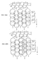
- Fig. 5(a) shows a pixel arrangement having four rows and five columns based on the original print data.
- Figs. 5(b) and 5(c) show converted states of the pixel layout in Fig. 5(a).
- Fig. 5(d) show values set to each pixel in the pixel layout of Fig. 5(c) that have been indicated in different colors.
- the PC 1 would output instructions to the printer 1A to form dots for each pixel based on the pixel layout in the original print data shown in Fig. 5(a) , and the printer 1A would eject ink droplets according to the instructions received from the PC 1.
- This method forms the dots shown in Fig. 1(a) .
- the pixel layout conversion program 45b converts the pixel layout shown in Fig. 5(a) to the layout shown in Fig. 5(b) . More specifically, the pixel layout conversion program 45b converts the pixel layout so that the second and fourth pixel columns are shifted in the subscanning direction H by half the pitch D in the subscanning direction H (1 ⁇ 2*D).
- the PC 1 outputs an instruction to the printer 1A to form dots for each pixel according to the converted pixel layout shown in Fig. 5(b) .
- the printer 1A ejects ink droplets based on these instructions. In this way, it is possible to form dots in the positions of impact shown in Fig. 4(a) .
- the pixel layout shown in Fig. 5 (a) is viewed as print data for printing a line-shaped image extending in the main scanning direction orthogonal to the subscanning direction H
- the pixel layout shown in Fig. 5(b) can be viewed as print data for forming a staggered image extending in the main scanning direction.
- the PC 1 outputs an instruction to the printer 1A to eject an additional ink droplet for one pixel worth in the opposite direction as the shifted direction for each shifted column in order to prevent distortion in the image.
- the pixel layout conversion program 45b converts the pixel layout shown in Fig. 5(a) to the layout shown in Fig. 5(c) rather than 5(b). Specifically, the pixel layout conversion program 45b adds new pixels "0-2" and "0-4" in the second and fourth columns, which are the pixel columns shifted in the subscanning direction H, at ends of the columns in the opposite direction from the shifted direction.
- the PC 1 outputs instructions to the printer 1A to reduce the density of dots corresponding to both ends of columns shifted in the subscanning direction H from the density according to the print data. Accordingly, the pixel value distribution program 45c sets the pixel values for pixels "0-2" and “4-2” and pixels "0-4" and "4-4" positioned on both ends of the second and fourth pixel columns shifted in the subscanning direction H lower than the pixel values corresponding to the print data.
- Pixel values are set for each pixel and define the density of the dot corresponding to the pixel.
- the pixel value may be represented by a value from 0 to 255, where a small ink droplet is ejected for pixels set to a value between 0 and 84, medium ink droplets are ejected for pixels set to a value between 85 and 169, and large ink droplets are ejected for a pixel set to a value between 169 and 255.
- Ink droplets of a larger size form darker dots.
- the density of dots formed on the printing medium may be regulated not only by the size of the ink droplet, but also by using a low density ink in colors other than magenta, yellow, cyan, and black.
- each pixel of the original print data shown in Fig. 5(a) may be set to the value 250 as the original pixel value.
- the printer 1A ejects large ink droplets to form large dots for each pixel based on the pixel value of each pixel.
- the PC 1 first converts the pixel layout shown in Fig. 5(a) to the layout shown in Fig. 5(c) based on the pixel layout conversion program 45b, and subsequently distributes part of the original pixel value 250 for the pixel "1-2" (a pixel value of 125) to the pixel "0-2" in the second pixel column based on the pixel value distribution program 45c, setting the pixel value for the pixel "0-2" to 125.
- the pixel value of the pixel "0-2" was originally set to 0 when first added by the pixel layout conversion program 45b.
- pixels "0-2” and “4-2” in the second column are ultimately set to 125, while pixels "1-2" through “3-2" are set to their original values of 250.
- the pixel value distribution program 45c sets pixels "0-2” and “4-2” and pixels "0-4" and “4-4" positioned on both ends of the second and fourth columns shifted in the subscanning direction H to the pixel value 125, which is half the value 250 corresponding to the print data.
- the PC 1 can output instructions to the printer 1A for setting the density of dots corresponding to pixels "0-2” and “4-2” and pixels "0-4" and "4-4" less than the density of dots corresponding to the other pixels.
- Fig. 6(a) shows the pixel layout based on the original print data.
- Fig. 6(b) shows the pixel layout of Fig. 6(a) after being converted.
- Fig. 6(c) shows pixel values that have been indicated in different colors for each pixel in the layout of Fig. 6(b) .
- the layout in Fig. 6(a) is converted to the layout shown in Fig. 6(b) according to the pixel layout conversion program 45b.
- pixels "1-2" and “1-4” are shifted in the subscanning direction H, and new pixels "0-2" and "0-4" are added to the side of the shifted pixels in the direction opposite the shifted direction.
- the pixel value distribution program 45c sets the values of each pixel in the layout shown in Fig. 6(b) as follows.
- each pixel in the original print data shown in Fig. 6(a) has been set to the original pixel value 250, while the newly added pixels "0-2" and "0-4" have been set to the pixel value 0.
- the partial pixel value 125 of the original pixel value 250 for the pixel "1-2" shifted in the subscanning direction H is distributed to the pixel "0-2” so that both the new pixel "0-2” and the pixel “1-2” are set to the pixel value 125.
- the partial pixel value 125 of the original pixel value 250 for the pixel "1-4" shifted in the subscanning direction H is distributed to the pixel "0-4" so that both the new pixel "0-4" and the pixel "1-4” are given the pixel value 125.
- Pixel values for pixels "1-1", “1-3", and "1-5" remain at 250.
- the pixel value distribution program 45c sets the values of pixels "0-2” and “1-2” and pixels "0-4" and “1-4” positioned at both ends of pixel columns shifted in the subscanning direction H to 125, which is half the pixel value of 250 specified in the print data. By doing this, it is possible to output instructions to the printer 1A for setting the density of dots corresponding to the pixels "0-2” and “1-2” and the pixels "0-4" and "1-4” less than the density of dots corresponding to other pixels.
- dots formed at the pixels "0-2" and “1-2” and pixels “0-4" and “1-4” are less conspicuous, even when printing a line-shaped image based on the pixel layout shown in Fig. 6(a) that is finer in the main scanning direction than the image shown in Fig. 5 .
- this method can prevent distortion in the line-shaped image.
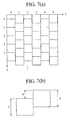
- Fig. 7(a) shows the state in which the pixel layout conversion program 45b has adapted the converted pixels to the XY coordinate system.
- Fig. 7(b) is a partially enlarged view of converted pixels illustrating the method of setting a distribution ratio.
- a coordinate system has been assigned to the pixel layout produced by shifting every other column in the subscanning direction H according to the pixel layout conversion program 45b.
- the uppermost pixel in the leftmost column is the point of origin
- the right direction is the X-axis
- the left direction is the Y-axis.
- each pixel is represented as L(X,Y), where X is set in a range from 0 to Xmax and Y is set to a range from 0 to Ymax.
- a distribution ratio R of pixel values is set based on the ratio of a shift amount S of the shifted pixels to a length T on one side of each pixel. Since pixels are shifted exactly one half the length of one side in the preferred embodiment, the distribution ratio R is 1/2.
- Fig. 8 is a flowchart illustrating steps in a pixel value distribution process.
- the CPU 44 executes this process based on the pixel value distribution program 45c.
- S1 of the process the CPU 44 initializes the coordinates (X,Y).
- S2 the CPU 44 determines whether the X is even. If X is odd (S2: NO), then in S9 the CPU 44 increments X by 1.
- the CPU 44 calculates a distribution amount M.
- the distribution amount M is calculated by multiplying the distribution ratio R by the pixel value L (X,Y+1) of the pixel adjacent to a target pixel in the +Y direction.
- the CPU 44 calculates the pixel value L (X,Y) of the target pixel.
- the value L (X,Y) of the target pixel is calculated by adding the distribution amount M to the value L (X,Y) of the target pixel.
- the CPU 44 decrements the pixel value L (X,Y+1) of the pixel adjacent to the target pixel in the +Y direction by the distribution amount M.
- the CPU 44 increments Y by 1 in order to process the next target pixel.
- the CPU 44 increments X by 1 in order to repeat the process described above on the next column of pixels.
- the CPU 44 determines whether the new value of X has reached the right end (Xmax+1). If so (S10: YES), the process ends. If not (S10: NO), then the CPU 44 repeats the process from S2.
- Fig. 9 shows the relationship between the nozzle 35a and the like and the dots formed by ink droplets ejected from the nozzle 35a and the like.
- Dots are formed in the main scanning direction at a smaller pitch than that of dots formed in the subscanning direction H by setting the pitch of the nozzle 35a and the like smaller than the conventional pitch in Fig. 1 while using the same ejection timing in the subscanning direction as the conventional timing in Fig. 1 .
- This method produces a larger overlapped area of neighboring dots formed in the main scanning direction than the overlapping area of neighboring dots formed in the subscanning direction H.
- the invention keeps the gap between the columns of dots B and C smaller than that shown in Fig. 1(b) , making the gap less noticeable in order to form images of high quality.
- the PC 1 of the invention outputs instructions to the printer 1A to form more dots in the subscanning direction based on the reduction in pitch of the nozzle 35a and the like.
- the ratio of the image size in the main scanning direction and subscanning direction H approaches the ratio of the image size corresponding to the print data, thereby reducing distortion in the image.
- the pixel layout conversion program 45b converts this pixel layout to a layout having four rows and eight columns by adding an additional four columns of pixels based on the reduction in size produced by reducing the pitch of the nozzle 35a and the like and outputs instructions to the printer 1A to eject ink droplets for each pixel in the converted pixel layout.
- This method brings the size ratio of the image in the main scanning direction and subscanning direction H near the size ratio in the original print data, thereby reducing distortion in the image.
- Fig. 10(a) shows the relationship between the nozzle 35a and the like and dots formed by ink droplets ejected from the nozzle 35a and the like.
- Fig. 10(b) shows the case of forming dots as shown in Fig. 10(a) when for some reason ink droplets ejected from the nozzle 35c land with a bias toward the nozzle 35d.
- every other column of dots is shifted in the subscanning direction H by about half a pitch D of the dots aligned in the subscanning direction H (1 ⁇ 2*D).
- the present invention sets a smaller pitch q than the conventional pitch in Fig. 1 and sets the ejection timing for the subscanning direction H the same as the ejection timing in Fig. 1 , and further outputs instructions to the printer 1A to form more dots in the main scanning direction based on the reduction in pitch of the nozzle 35a and the like.
- This control can reduce the gap produced between the columns of dots B and C more than the conventional method shown in Fig. 1(b) , even when ink droplets expected to land as shown in Fig. 10 (a) form a column of dots C with a bias toward the column of dots D, as shown in Fig. 10(b) , because the nozzle 35c ejects ink droplets with a bias toward the nozzle 35d for some reason.
- Figs. 11(a) and 11(b) show the relationship between the nozzle 35a and the like and dots formed by ink droplets ejected from the nozzle 35a and the like.
- the control process described above shifts every other column of dots in the subscanning direction H and is capable of compensating for nozzles that eject ink droplets in a slanted direction relative to the printing medium, even without identifying those nozzles.
- the control process of Fig. 11 compensates for nozzles that eject ink droplets in a slanted direction to the printing medium by first identifying those nozzles.
- a CCD line scanner for example, is used to read the gaps produced between each column of dots based on the density differential. This data is used to determine when the pitch of neighboring dots in the main scanning direction is greater than the prescribed pitch and to identify the two nozzles forming dots at this position.
- the nozzle 35c ejects ink droplets with a bias toward the nozzle 35d so that the pitch D2 between the columns of dots B and C is greater than the pitch of other neighboring columns, then in the preferred embodiment the nozzle 35b and nozzle 35c are identified as the two nozzles.
- One of the two nozzles 35b and 35c is then controlled so that only dots formed by ink droplets ejected from this nozzle are shifted in the subscanning direction H.
- Fig. 11(a) shows the dot pattern when the column of dots B corresponding to the pixel layout conversion program 45b is shifted in the subscanning direction H.
- the method of the present embodiment can reduce the gap produced between the columns of dots B and C more than the conventional method shown in Fig. 1(b) when the nozzle 35c ejects ink droplets with a bias toward the nozzle 35d so that the column of dots C is formed closer to the column of dots D.
- Fig. 11(b) shows a dot pattern formed when the column of dots C corresponding to the nozzle 35c is shifted in the subscanning direction H.
- this method also reduces the gap produced between the columns of dots B and C more than the conventional method shown in Fig. 1(b) when the nozzle 35c ejects ink droplets with a bias toward the nozzle 35d so that the column of dots C is formed closer to the column of dots D.
- the method of the present example can minimize the number of dot columns shifted in the subscanning direction H to suppress distortion in the image, rather than shifting every other column of dots as in the control process as seen in the example with reference to Fig. 4 .
- the example described above addresses the case of ink droplets for forming the column of dots C landing at positions deviating in the main scanning direction.
- ink droplets impact the printing medium at positions deviating in the subscanning direction H, it is possible to shift a row of dots in the main scanning direction.
- Fig. 12 is a block diagram showing the general structure of an electric circuit in the inkjet printer 2A.
- the inkjet printer 2A (hereinafter abbreviated as "printer 2A") has a similar structure to the printer 1A described above, but stores the ink ejection control program 45a in the ROM 21 and the dot level table 47a in the EEPROM 23.
- the ink ejection control program 45a and dot level table 47a installed on the PC 1 in the description above may be installed directly on the printer 2A so that the processes performed on the PC 1 may be executed in the printer 2A.
- the printer 2A having this configuration can form images of high quality.
- a plurality of ink droplets having a prescribed volume can be combined in flight or on the printing medium, effectively producing a larger surface area of a dot formed by the combined ink droplets.
- the printer 1A that ejects ink from the nozzles with drive elements, it is possible to use a printer having a heat source for each nozzle, wherein ink is ejected from each nozzle according to heat produced by the heat sources. In such a case, the size of dots formed with each nozzle can be controlled by controlling the amount of heat produced in each heat source.
- a device for detecting such gaps may also be incorporated in the printer 1A. This configuration therefore does not require a separate detecting device, eliminating the stress of having to detect gaps using a separate detecting device.
- the gap formed between dots can be reduced by controlling the timing at which ink droplets are ejected from the nozzle.
- Fig. 10 and Fig. 11 described above address the case of shifting every other column or a specific column of dots in the subscanning direction H
- the PC 1 is used as the print controlling means by connecting the PC 1 to the printer 1A via the interface 48.
- the control performed by the PC 1 may also be implemented in the printer 1A by installing the various programs stored in the ROM 45 of the PC 1 on the printer 1A. In this case, printing can be controlled by the PC 1 when print data is received from a PC not provided with such programs.
Landscapes
- Engineering & Computer Science (AREA)
- Quality & Reliability (AREA)
- Ink Jet (AREA)
Claims (8)
- Tintenstrahlaufzeichnungsvorrichtung (1A), welche Düsen (35a - 35h) aufweist, die in einer ersten Richtung innerhalb eines Druckbereichs von einem Druckmedium zum Ausstoßen von Tintentropfen angeordnet sind, sowie einen Zeilenkopf (3) aufweist, in welchem die Düsen (35a - 35h) ausgestaltet sind, ist dazu konfiguriert, sich relativ zu dem Druckmedium in eine zweite Richtung orthogonal zu der ersten Richtung zu bewegen, zum Erzeugen eines Bildes auf dem Druckmedium,
wobei die Düsen (35a - 35h) mit einem Abstand (q) in der ersten Richtung angeordnet sind, welcher kleiner ist als ein Abstand (D) von Punkten in der zweiten Richtung, welche durch aus den Düsen (35a - 35h) ausgestoßenen Tintentropfen erzeugt werden und auf das Druckmedium auftreffen; und
die Vorrichtung derartig konfiguriert ist, dass ein überlappender Bereich von benachbarten Punkten in der ersten Richtung größer ist als ein überlappender Bereich von Punkten in der zweiten Richtung. - Tintenstrahlaufzeichnungsvorrichtung (1A) gemäß Anspruch 1, des Weiteren aufweisend eine Ausgabeeinheit (45b), welche dazu konfiguriert ist, Befehle auszugeben zum Ausstoßen von Tintentropfen aus den Düsen gegen das Druckmedium, so dass diese auf das Druckmedium an vorgeschriebenen Positionen auftreffen, zum Erzeugen von Punkten, korrespondierend zu den Druckdaten;
wobei die Ausgabeeinheit (45b) dazu konfiguriert ist, Befehlen zum Erzeugen von mehr Punkten in der ersten Richtung, als die Anzahl in den Druckdaten angibt, auszugeben, basierend auf dem Abstand (q) der Düsen (35a - 35h) in der ersten Richtung, welcher kleiner ist, als der Abstand (D) von benachbarten Punkten in der zweiten Richtung. - Tintenstrahlaufzeichnungsvorrichtung (1A) gemäß Anspruch 1, des Weiteren aufweisend eine Steuerung (1), welche dazu konfiguriert ist, die Tintenstrahlaufzeichnungsvorrichtung (1A) zu steuern, durch Ausgabe von Befehlen an die Tintenstrahlaufzeichnungsvorrichtung (1A), Tintentropfen aus den Düsen (35a - 35h) gegen das Druckmedium auszustoßen, so dass die Tintentropfen auf das Druckmedium auftreffen, um Punkte an vorgeschriebenen Positionen zu erzeugen, korrespondierend zu den Druckdaten;
wobei die Steuerung (1) eine Ausgabeeinheit (45b) aufweist, welche dazu konfiguriert ist, Befehle an die Tintenstrahlaufzeichnungsvorrichtung (1A) auszugeben, so dass Spalten von Punkten (A - E), welche sich in die zweite Richtung erstrecken, in die zweite Richtung verschoben werden, zumindest an jeder zweiten Spalte. - Tintenstrahlaufzeichnungsvorrichtung (1A) gemäß Anspruch 1, des Weiteren eine Steuerung (1) aufweisend, welche dazu konfiguriert ist, die Tintenstrahlaufzeichnungsvorrichtung (1A) zu steuern, durch Ausgabe von Befehlen an die Tintenstrahlaufzeichnungsvorrichtung (1A), Tintentropfen aus den Düsen (35a - 35h) gegen das Druckmedium auszustoßen, so dass die Tintentropfen auf das Druckmedium auftreffen, um Punkte an vorgeschriebenen Positionen zu erzeugen, basierend auf den Druckdaten;
wobei die Steuerung (1) eine Ausgabeeinheit aufweist, welche dazu konfiguriert ist, Befehle an die Tintenstrahlaufzeichnungsvorrichtung (1A) auszugeben, so dass benachbarte Punkte in der zweiten Richtung, orthogonal zu der ersten Richtung, einen geringeren Abstand aufweisen als benachbarte Punkte in der ersten Richtung, durchgehend in einem Druckbereich auf dem Druckmedium. - Tintenstrahlaufzeichnungsvorrichtung (1A) gemäß Anspruch 1, des Weiteren aufweisend eine Steuerung (1), welche dazu konfiguriert ist, die Tintenstrahlaufzeichnungsvorrichtung (1A) zu steuern, wobei die Tintenstrahlaufzeichnungsvorrichtung (1A) eine Vielzahl von Düsen aufweist, welche in einer ersten Richtung angeordnet sind, orthogonal zu einer zweiten Richtung, zum Erzeugen von Bildern durch Bewegung in die zweite Richtung, relativ zu einem Druckmedium, durch Ausgabe von Befehlen an die Tintenstrahlaufzeichnungsvorrichtung (1A), Tintentropfen aus den Düsen (35a - 35h) gegen das Druckmedium auszustoßen, so dass die ausgestoßenen Tintentropfen Punkte auf dem Druckmedium an vorgeschriebenen Positionen erzeugen, welche in den Druckdaten spezifiziert sind,
wobei die Steuerung (1) eine Ausgabeeinheit aufweist, welche Befehle an die Tintenstrahlaufzeichnungsvorrichtung (1A) ausgibt, so dass Punkte, welche durch aus einer ersten Düse (35b) ausgetretenen Tintentropfen erzeugt wurden, in die zweite Richtung verschoben werden, wobei die erste Düse (35b) wenigstens eine von zwei Düsen (35b, 35c) ist, welche Tintentropfen ausstoßen, die auf Positionen auftreffen, zum Erzeugen von benachbarten Punkten in der ersten Richtung mit einem Abstand, welcher größer ist als ein vorgeschriebener Abstand. - Tintenstrahlaufzeichnungsvorrichtung (1A) gemäß Anspruch 1, des Weiteren aufweisend eine Speichereinheit, welche dazu konfiguriert ist, ein Steuerprogramm (45a) zu speichern, zum Steuern der Tintenstrahlaufzeichnungsvorrichtung (1A), welche eine Vielzahl von Düsen aufweist, die in einer ersten Richtung orthogonal zu einer zweiten Richtung aneinandergereiht sind, welche in der zweiten Richtung relativ zu einem Druckmedium bewegt werden, zum Erzeugen von Bildern darauf, durch Ausgabe von Befehlen an die Tintenstrahlaufzeichnungsvorrichtung (1A), zum Ausstoßen von Tintentropfen aus den Düsen gegen das Druckmedium, so dass die Tintentropfen auf das Druckmedium auftreffen, um Punkte an vorgeschriebenen Positionen zu erzeugen, korrespondierend zu den Druckdaten,
wobei das Steuerprogramm (45a) einen Ausgabeschritt aufweist, der dazu konfiguriert ist, Befehle an die Tintenstrahlaufzeichnungsvorrichtung (1A) auszugeben, so dass Spalten von Punkten (A - E), welche sich in die zweite Richtung erstrecken, in die zweite Richtung verschoben werden, zumindest an jeder zweiten Spalte. - Die Tintenstrahlaufzeichnungsvorrichtung (1A) gemäß Anspruch 1, des Weiteren aufweisend eine Speichereinheit, welche dazu konfiguriert ist, ein Steuerprogramm (45a) zu speichern, zum Steuern der Tintenstrahlaufzeichnungsvorrichtung (1A), welche eine Vielzahl von Düsen (35a - 35h) aufweist, welche in einer ersten Richtung orthogonal zu einer zweiten Richtung angeordnet sind, zum Erzeugen von Bildern durch Bewegung in die zweite Richtung relativ zu dem Druckmedium, durch Ausgabe von Befehlen an die Tintenstrahlaufzeichnungsvorrichtung (1A), Tintentropfen aus den Düsen (35a - 35h) gegen das Druckmedium auszustoßen, so dass die Tintentropfen auf das Druckmedium auftreffen, zum Erzeugen von Punkten (A - H) an vorgeschriebenen Positionen, basierend auf den Druckdaten;
wobei das Steuerprogramm (45a) einen Ausgabeschritt aufweist, welcher dazu konfiguriert ist, Ausgabebefehle an die Tintenstrahlaufzeichnungsvorrichtung (1A) auszugeben, so dass benachbarte Punkte (A - H) in der zweiten Richtung, orthogonal zu der ersten Richtung, einen geringeren Abstand (q) aufweisen, als ein Abstand (D) von benachbarten Punkten in der ersten Richtung, durchgehend in einem Druckbereich auf dem Druckmedium. - Tintenstrahlaufzeichnungsvorrichtung (1A) gemäß Anspruch 1, des Weiteren aufweisend eine Speichereinheit, welche dazu konfiguriert ist, ein Steuerprogramm (45a) zu speichern, zum Steuern der Tintenstrahlaufzeichnungsvorrichtung (1A), welche eine Vielzahl von Düsen aufweist, welche in einer ersten Richtung orthogonal zu einer zweiten Richtung angeordnet sind, zum Erzeugen von Bildern durch Bewegung in die zweite Richtung relativ zu dem Druckmedium, durch Ausgabe von Befehlen an die Tintenstrahlaufzeichnungsvorrichtung (1A), Tintentropfen aus den Düsen (35a - 35h) gegen das Druckmedium auszustoßen, so dass die Tintentropfen auf das Druckmedium auftreffen, zum Erzeugen von Punkten an vorgeschriebenen Positionen, spezifiziert in den Druckdaten;
wobei das Steuerprogramm (45a) einen Ausgabeschritt aufweist, welcher dazu konfiguriert ist, Befehle an die Tintenstrahlaufzeichnungsvorrichtung (1A) auszugeben, so dass Punkte, welche durch aus einer ersten Düse (35b) ausgetretenen Tintentropfen erzeugt wurden, in die zweite Richtung verschoben werden, die erste Düse (35b) wenigstens eine von zwei Düsen (35b, 35c) ist, welche Tintentropfen ausstoßen, die auf Positionen auftreffen, zum Erzeugen von benachbarten Punkten in der ersten Richtung mit einem Abstand, welcher größer ist als ein vorgeschriebener Abstand.
Applications Claiming Priority (3)
| Application Number | Priority Date | Filing Date | Title |
|---|---|---|---|
| JP2004232908A JP4770138B2 (ja) | 2004-08-10 | 2004-08-10 | インクジェット記録装置用制御装置、インクジェット記録装置用制御プログラム、インクジェット記録装置の制御方法およびインクジェット記録装置 |
| JP2004253608A JP4687037B2 (ja) | 2004-08-31 | 2004-08-31 | 印刷制御装置および印刷手段の制御方法 |
| EP05753328A EP1787815B1 (de) | 2004-08-10 | 2005-06-27 | Verfahren zur steuerung eines tintenstrahlaufzeichners und tintenstrahlaufzeichner |
Related Parent Applications (2)
| Application Number | Title | Priority Date | Filing Date |
|---|---|---|---|
| EP05753328.3 Division | 2005-06-27 | ||
| EP05753328A Division EP1787815B1 (de) | 2004-08-10 | 2005-06-27 | Verfahren zur steuerung eines tintenstrahlaufzeichners und tintenstrahlaufzeichner |
Publications (3)
| Publication Number | Publication Date |
|---|---|
| EP2409842A2 EP2409842A2 (de) | 2012-01-25 |
| EP2409842A3 EP2409842A3 (de) | 2012-05-16 |
| EP2409842B1 true EP2409842B1 (de) | 2014-03-19 |
Family
ID=35839228
Family Applications (2)
| Application Number | Title | Priority Date | Filing Date |
|---|---|---|---|
| EP11185814.8A Expired - Lifetime EP2409842B1 (de) | 2004-08-10 | 2005-06-27 | Tintenstrahlaufzeichner |
| EP05753328A Expired - Lifetime EP1787815B1 (de) | 2004-08-10 | 2005-06-27 | Verfahren zur steuerung eines tintenstrahlaufzeichners und tintenstrahlaufzeichner |
Family Applications After (1)
| Application Number | Title | Priority Date | Filing Date |
|---|---|---|---|
| EP05753328A Expired - Lifetime EP1787815B1 (de) | 2004-08-10 | 2005-06-27 | Verfahren zur steuerung eines tintenstrahlaufzeichners und tintenstrahlaufzeichner |
Country Status (3)
| Country | Link |
|---|---|
| US (2) | US8113615B2 (de) |
| EP (2) | EP2409842B1 (de) |
| WO (1) | WO2006016452A1 (de) |
Families Citing this family (14)
| Publication number | Priority date | Publication date | Assignee | Title |
|---|---|---|---|---|
| JP2008114435A (ja) * | 2006-11-02 | 2008-05-22 | Fuji Xerox Co Ltd | 液滴吐出装置、液滴吐出装置の制御方法及びコンピュータのプログラム |
| TW201103307A (en) * | 2009-07-10 | 2011-01-16 | Shanghai Microtek Technology Co Ltd | Calibrating device, mapping and compensation method for image sensors |
| JP2011110802A (ja) * | 2009-11-26 | 2011-06-09 | Mimaki Engineering Co Ltd | 印刷データ生成装置、印刷データ生成方法及び印刷データ生成プログラム |
| CN102582307B (zh) * | 2011-01-10 | 2014-10-22 | 研能科技股份有限公司 | 快速宽幅打印方法及适用该快速宽幅打印方法的打印装置 |
| JP2013169760A (ja) | 2012-02-22 | 2013-09-02 | Fujifilm Corp | インクジェット記録装置及びその画像記録方法 |
| JP5871686B2 (ja) | 2012-03-28 | 2016-03-01 | 株式会社Screenホールディングス | 画像記録装置および画像記録方法 |
| JP6232871B2 (ja) * | 2013-09-12 | 2017-11-22 | セイコーエプソン株式会社 | インクジェットプリンター、および印刷方法 |
| US10046560B2 (en) | 2014-07-31 | 2018-08-14 | Hewlett-Packard Development Company, L.P. | Methods and apparatus to control a heater associated with a printing nozzle |
| WO2016018389A1 (en) | 2014-07-31 | 2016-02-04 | Hewlett-Packard Development Company, L.P. | Methods and apparatus to reduce ink evaporation in printhead nozzles |
| US9361554B2 (en) * | 2014-09-26 | 2016-06-07 | Ricoh Company, Ltd. | Low overhead near unity scaling technique |
| JP6652128B2 (ja) * | 2015-03-31 | 2020-02-19 | コニカミノルタ株式会社 | インクジェット記録装置、インクジェットヘッド駆動方法及び画像形成方法 |
| JP6825564B2 (ja) | 2015-07-21 | 2021-02-03 | セイコーエプソン株式会社 | ライン型インクジェットプリンター及びラインヘッド |
| CN111746123B (zh) * | 2020-06-08 | 2024-03-26 | 深圳圣德京粤科技有限公司 | 一种多喷头打印装置及其打印方法 |
| JP7676832B2 (ja) * | 2021-03-12 | 2025-05-15 | セイコーエプソン株式会社 | 立体物印刷方法および立体物印刷装置 |
Family Cites Families (23)
| Publication number | Priority date | Publication date | Assignee | Title |
|---|---|---|---|---|
| US4095421A (en) * | 1976-01-26 | 1978-06-20 | Chevron Research Company | Subsea energy power supply |
| JPS6415382A (en) | 1987-07-08 | 1989-01-19 | Tokuriki Honten Kk | Oxidation inhibiting solution |
| JPH02192955A (ja) | 1989-01-20 | 1990-07-30 | Matsushita Electric Ind Co Ltd | 記録方法 |
| JPH1058714A (ja) * | 1996-07-01 | 1998-03-03 | Xerox Corp | 記録媒体の上に画像を印刷する方法 |
| JPH1015382A (ja) | 1996-07-02 | 1998-01-20 | Mitsubishi Heavy Ind Ltd | 吸収装置の充填物およびその製造方法 |
| US5733623A (en) | 1996-10-15 | 1998-03-31 | Eastman Kodak Company | Recording media for recordable element |
| JPH10235854A (ja) | 1997-02-21 | 1998-09-08 | Konica Corp | インクジェットプリンタ |
| JPH11215363A (ja) | 1998-01-28 | 1999-08-06 | Toshiba Tec Corp | 画像形成装置 |
| JPH11309857A (ja) | 1998-04-28 | 1999-11-09 | Minolta Co Ltd | インクジェット式記録装置 |
| ATE307031T1 (de) | 1998-05-21 | 2005-11-15 | Canon Kk | Tintenstrahldruckverfahren und tintenstrahldruckgerät |
| ATE352419T1 (de) * | 1999-03-10 | 2007-02-15 | Seiko Epson Corp | Einstellung der verschiebung der punktbildungslage unter verwendung von informationen, gemäss welcher nicht für jede pixeleinheit ein punkt gebildet werden muss |
| JP2000326497A (ja) | 1999-05-21 | 2000-11-28 | Hitachi Koki Co Ltd | インクジェット印刷装置の印刷方法 |
| GB9918020D0 (en) * | 1999-07-30 | 1999-09-29 | Unilever Plc | Detergent compositions |
| US7075677B1 (en) | 2000-06-30 | 2006-07-11 | Silverbrook Research Pty Ltd | Ink jet fault tolerance using oversize drops |
| US6375294B1 (en) * | 2000-11-28 | 2002-04-23 | Xerox Corporation | Gray scale fluid ejection system with offset grid patterns of different size spots |
| JP2002240287A (ja) | 2001-02-20 | 2002-08-28 | Sony Corp | プリンタヘッド、プリンタ及びプリンタヘッドの駆動方法 |
| US6659589B2 (en) | 2001-07-20 | 2003-12-09 | Hewlett-Packard Development Company, L.P. | System and method for producing efficient ink drop overlap filled with a pseudo hexagonal grid pattern |
| US7407264B2 (en) | 2002-10-01 | 2008-08-05 | Sony Corporation | Liquid discharging apparatus and liquid discharging method |
| JP4172430B2 (ja) * | 2004-07-07 | 2008-10-29 | 富士フイルム株式会社 | 画像形成装置 |
| JP2006159810A (ja) * | 2004-12-10 | 2006-06-22 | Seiko Epson Corp | 印刷装置及び印刷用画像処理装置 |
| JP2006205717A (ja) * | 2004-12-27 | 2006-08-10 | Seiko Epson Corp | 印刷装置、印刷プログラム、印刷方法、および画像処理装置、画像処理プログラム、画像処理方法、並びに前記プログラムを記録した記録媒体 |
| JP4434112B2 (ja) * | 2004-12-28 | 2010-03-17 | セイコーエプソン株式会社 | 印刷装置、印刷装置制御プログラム及び印刷装置制御方法 |
| JP4736766B2 (ja) * | 2005-03-29 | 2011-07-27 | セイコーエプソン株式会社 | 印刷装置、印刷プログラム、印刷方法および画像処理装置、画像処理プログラム、画像処理方法、並びに前記プログラムを記録した記録媒体 |
-
2005
- 2005-06-27 US US11/659,831 patent/US8113615B2/en active Active
- 2005-06-27 WO PCT/JP2005/011757 patent/WO2006016452A1/ja not_active Ceased
- 2005-06-27 EP EP11185814.8A patent/EP2409842B1/de not_active Expired - Lifetime
- 2005-06-27 EP EP05753328A patent/EP1787815B1/de not_active Expired - Lifetime
-
2012
- 2012-01-19 US US13/353,456 patent/US8500231B2/en not_active Expired - Fee Related
Also Published As
| Publication number | Publication date |
|---|---|
| US8500231B2 (en) | 2013-08-06 |
| EP2409842A3 (de) | 2012-05-16 |
| US20080238966A1 (en) | 2008-10-02 |
| EP1787815B1 (de) | 2012-02-15 |
| EP1787815A4 (de) | 2010-04-14 |
| WO2006016452A1 (ja) | 2006-02-16 |
| US20120113173A1 (en) | 2012-05-10 |
| EP2409842A2 (de) | 2012-01-25 |
| US8113615B2 (en) | 2012-02-14 |
| EP1787815A1 (de) | 2007-05-23 |
Similar Documents
| Publication | Publication Date | Title |
|---|---|---|
| US8500231B2 (en) | Inkjet recording device and controller, control program and control method for inkjet recording device for gap reduction of ink droplets | |
| CN100473531C (zh) | 液体排放设备和液体排放方法 | |
| JP2011031611A (ja) | 記録装置及びプログラム | |
| JP5480765B2 (ja) | ライン型インクジェットプリンタの色別インク吐出量調整装置 | |
| US20110298853A1 (en) | Printing apparatus and processing method thereof | |
| US20130241997A1 (en) | Ink jet printing apparatus and ink jet printing method | |
| WO2000030857A1 (fr) | Imprimante a points possedant une synchronisation reglable | |
| CN101001753B (zh) | 喷墨记录设备和用于喷墨记录设备的控制器、控制程序以及控制方法 | |
| US9731527B2 (en) | Liquid droplet discharging apparatus and liquid droplet discharging method | |
| JP5247006B2 (ja) | インクジェット記録装置およびインクジェット記録方法 | |
| JP2001018387A (ja) | 印刷装置 | |
| JP4687037B2 (ja) | 印刷制御装置および印刷手段の制御方法 | |
| US8641159B2 (en) | Liquid ejecting apparatus | |
| JP6388027B2 (ja) | 画像形成装置及び画像形成方法 | |
| JP5224684B2 (ja) | インクジェット記録装置およびインクジェット記録方法 | |
| JP7017055B2 (ja) | 液滴吐出装置および液滴吐出調整方法 | |
| JP5257032B2 (ja) | 印刷装置 | |
| JP4244781B2 (ja) | プラテンを汚すことなく印刷用紙の端部まで行う印刷 | |
| JP6885006B2 (ja) | 印刷装置 | |
| JP5031234B2 (ja) | インクジェット記録装置および記録方法 | |
| JP2011251479A (ja) | 記録装置及びその着弾位置調整方法 | |
| JP2009051063A (ja) | 画像形成装置 | |
| JP2009056661A (ja) | 印刷装置および印刷方法 | |
| JP2007145031A (ja) | 双方向印刷方法および装置 | |
| JP4715965B2 (ja) | プラテンを汚すことなく印刷用紙の端部まで行う印刷 |
Legal Events
| Date | Code | Title | Description |
|---|---|---|---|
| AC | Divisional application: reference to earlier application |
Ref document number: 1787815 Country of ref document: EP Kind code of ref document: P |
|
| AK | Designated contracting states |
Kind code of ref document: A2 Designated state(s): DE FR GB |
|
| PUAI | Public reference made under article 153(3) epc to a published international application that has entered the european phase |
Free format text: ORIGINAL CODE: 0009012 |
|
| REG | Reference to a national code |
Ref country code: DE Ref legal event code: R079 Ref document number: 602005043056 Country of ref document: DE Free format text: PREVIOUS MAIN CLASS: B41J0002010000 Ipc: B41J0002210000 |
|
| PUAL | Search report despatched |
Free format text: ORIGINAL CODE: 0009013 |
|
| AK | Designated contracting states |
Kind code of ref document: A3 Designated state(s): DE FR GB |
|
| RIC1 | Information provided on ipc code assigned before grant |
Ipc: B41J 2/21 20060101AFI20120411BHEP Ipc: B41J 2/045 20060101ALI20120411BHEP |
|
| 17P | Request for examination filed |
Effective date: 20121116 |
|
| GRAP | Despatch of communication of intention to grant a patent |
Free format text: ORIGINAL CODE: EPIDOSNIGR1 |
|
| INTG | Intention to grant announced |
Effective date: 20131008 |
|
| GRAS | Grant fee paid |
Free format text: ORIGINAL CODE: EPIDOSNIGR3 |
|
| GRAA | (expected) grant |
Free format text: ORIGINAL CODE: 0009210 |
|
| AC | Divisional application: reference to earlier application |
Ref document number: 1787815 Country of ref document: EP Kind code of ref document: P |
|
| AK | Designated contracting states |
Kind code of ref document: B1 Designated state(s): DE FR GB |
|
| REG | Reference to a national code |
Ref country code: GB Ref legal event code: FG4D |
|
| REG | Reference to a national code |
Ref country code: DE Ref legal event code: R096 Ref document number: 602005043056 Country of ref document: DE Effective date: 20140430 |
|
| REG | Reference to a national code |
Ref country code: DE Ref legal event code: R097 Ref document number: 602005043056 Country of ref document: DE |
|
| PLBE | No opposition filed within time limit |
Free format text: ORIGINAL CODE: 0009261 |
|
| STAA | Information on the status of an ep patent application or granted ep patent |
Free format text: STATUS: NO OPPOSITION FILED WITHIN TIME LIMIT |
|
| 26N | No opposition filed |
Effective date: 20141222 |
|
| REG | Reference to a national code |
Ref country code: DE Ref legal event code: R097 Ref document number: 602005043056 Country of ref document: DE Effective date: 20141222 |
|
| REG | Reference to a national code |
Ref country code: FR Ref legal event code: PLFP Year of fee payment: 12 |
|
| REG | Reference to a national code |
Ref country code: FR Ref legal event code: PLFP Year of fee payment: 13 |
|
| REG | Reference to a national code |
Ref country code: FR Ref legal event code: PLFP Year of fee payment: 14 |
|
| PGFP | Annual fee paid to national office [announced via postgrant information from national office to epo] |
Ref country code: FR Payment date: 20180516 Year of fee payment: 14 |
|
| PGFP | Annual fee paid to national office [announced via postgrant information from national office to epo] |
Ref country code: GB Payment date: 20180403 Year of fee payment: 14 |
|
| GBPC | Gb: european patent ceased through non-payment of renewal fee |
Effective date: 20190627 |
|
| PG25 | Lapsed in a contracting state [announced via postgrant information from national office to epo] |
Ref country code: GB Free format text: LAPSE BECAUSE OF NON-PAYMENT OF DUE FEES Effective date: 20190627 |
|
| PG25 | Lapsed in a contracting state [announced via postgrant information from national office to epo] |
Ref country code: FR Free format text: LAPSE BECAUSE OF NON-PAYMENT OF DUE FEES Effective date: 20190630 |
|
| PGFP | Annual fee paid to national office [announced via postgrant information from national office to epo] |
Ref country code: DE Payment date: 20240509 Year of fee payment: 20 |
|
| REG | Reference to a national code |
Ref country code: DE Ref legal event code: R071 Ref document number: 602005043056 Country of ref document: DE |