EP2409911A2 - Voilier - Google Patents
Voilier Download PDFInfo
- Publication number
- EP2409911A2 EP2409911A2 EP10178523A EP10178523A EP2409911A2 EP 2409911 A2 EP2409911 A2 EP 2409911A2 EP 10178523 A EP10178523 A EP 10178523A EP 10178523 A EP10178523 A EP 10178523A EP 2409911 A2 EP2409911 A2 EP 2409911A2
- Authority
- EP
- European Patent Office
- Prior art keywords
- sailboat
- jib
- hull
- center line
- mast
- Prior art date
- Legal status (The legal status is an assumption and is not a legal conclusion. Google has not performed a legal analysis and makes no representation as to the accuracy of the status listed.)
- Withdrawn
Links
- 230000008878 coupling Effects 0.000 claims description 8
- 238000010168 coupling process Methods 0.000 claims description 8
- 238000005859 coupling reaction Methods 0.000 claims description 8
- 241000380131 Ammophila arenaria Species 0.000 abstract 1
- 238000010586 diagram Methods 0.000 description 26
- 238000007664 blowing Methods 0.000 description 12
- 230000008859 change Effects 0.000 description 4
- 230000004044 response Effects 0.000 description 4
- 230000001419 dependent effect Effects 0.000 description 2
- 238000010276 construction Methods 0.000 description 1
- 238000000034 method Methods 0.000 description 1
- 230000004048 modification Effects 0.000 description 1
- 238000012986 modification Methods 0.000 description 1
Images






Classifications
-
- B—PERFORMING OPERATIONS; TRANSPORTING
- B63—SHIPS OR OTHER WATERBORNE VESSELS; RELATED EQUIPMENT
- B63H—MARINE PROPULSION OR STEERING
- B63H9/00—Marine propulsion provided directly by wind power
- B63H9/04—Marine propulsion provided directly by wind power using sails or like wind-catching surfaces
- B63H9/06—Types of sail; Constructional features of sails; Arrangements thereof on vessels
Definitions
- the present invention relates to a sailboat, and more particularly, to a sailboat with left and right jibs.
- sailboats may be distinguished by the number of masts being established and thus can be divided into two categories, i.e. single-masted sailboats and multi-masted sailboats. It is noted that the multi-masted sailboats include double-masted sailboats and three-masted sailboats, but are not limited thereby. Moreover, traditional sailboats are monohulls, but multi-hull catamarans and trimarans are gaining popularity.
- a monohull sailboat has only one mast, it is a single-masted monohull sailboat; and if there is more than one mast on a sailboat, it can be a multi-masted monohull sailboat.
- the sailboat is a single-masted sailboat, but it is not limited thereby.
- FIG. 1A is a schematic diagram showing a conventional single-masted monohull sailboat. As shown in FIG.
- the single-masted monohull sailboat 1 includes: a hull 10, a mast 11, a fixing element 12, a winch 13, a pulley 130, a jib 14, a boom 15 and a mainsail 16, in which the hull 10 is further configured with a center line 100, a bow 101, a midship 102, a stem 103, a port side 104 and a starboard side 105; the mast 11 is configured with a first end 110 and a second end 111 at positions opposite to each other while coupling the first end 110 to the center line 100 at a position between the bow 101 and the stem 103 as the center line 100 is arranged connecting the bow 101 and the stem 103, i.e.
- the center line 100 is the fore-aft center line of the sailboat 1;
- the fixing element 12 is disposed at the bow 101 of the hull 10;
- the winch 13 is disposed on the hull 10;
- the pulley 130 is coupled to either the starboard side 105 or the port side 104;
- the jib 14, being configured with a plurality of ends, is configured with a first end 140, a second end 141 and a third end 142 in this embodiment in a manner that the first end 140 is connected to the second end 111 of the mast 11, the second end 141 is connected to the fixing element 12, and the third end 142 is connected to the winch 13 by way of the pulley 130;
- the boom 15 is configured with a first end 150 and a second end 151 at positions opposite to each other while enabling the first end 150 to be coupled with the mast 11;
- the mainsail 16, being configured with a plurality of ends is configured with a first end 160, a second end 161 and a third end
- FIG. 1B is a top view of a conventional single-masted monohull sailboat.
- the current sail configuration enables the sailboat 1 to be driven by the wind coming from a direction 010 at an included angle not smaller than 25 degrees with respect to the center line 100, that is, if the included angle between the wind direction 010 and the center line 100 is smaller than 25 degrees, the wind will not be able to be used by sailboat 1 efficiently for driving the sailboat 1 to move accordingly.
- the sailing trajectory of the sailboat 1 is a zigzagging path 2 as the one shown in FIG. 1C .
- the sailboat 1 will not be able to move in a straightline to its destination 21, but have to zigzag all the way from the point of departure 20 to the destination 21.
- the single-masted catamaran 3 includes: a hull module 30, a mast 31, a fixing element 32, a winch 33, a pulley 330, a jib 34, a boom 35 and a mainsail 36.
- the hull module 30 is further configured with: a first hull 300 having a first bow 3000 and a first stern 3001; a second hull 301 having a second bow 3010 and a second stern 3011; a center line 302; a starting end 303, defined to be the frontmost point on the center line 302 where it is intersected with the hull module 30; a midship 304; a terminating end 305, defined to the rearmost point on the center line 302 where it is intersected with the hull module 30; a port side 306; and a starboard side 307; the mast 31 is configured with a first end 310 and a second end 311 at positions opposite to each other while coupling the first end 310 to the center line 100 at a position between the starting end 303 and the midship 304 as the center line 302 is defined to be a line connecting the center between the first bow 3000 and the second bow 3010 and the center between the first stern 3001 and the second stern 3011; the
- FIG. 2B is a top view of a conventional single-masted catamaran.
- the current sail configuration enables the catamaran 3 to be driven by the wind coming from a direction 010 at an included angle not smaller than 42 degrees with respect to the center line 302, that is, if the included angle between the wind direction 010 and the center line 302 is smaller than 42 degrees, the wind will not be able to be used by catamaran 3 efficiently for driving the catamaran 3 to move accordingly.
- the sailing trajectory of the catamaran 3 is a zigzagging path 4 as the one shown in FIG. 2C .
- the catamaran 3 will not be able to move in a straightline to its destination 41, but have to zigzag all the way from the point of departure 40 to the destination 41.
- the moving efficiency of the conventional sailboats with respect to the shorting of voyage distance is not satisfactory.
- the primary object of the present invention is to provide a less-expensive, easy-to-operate sailboat with high sailing efficiency that is designed to operate its left jib and right jib in an alternating manner and is capable of shorting its voyage distance to a destination effectively.
- the present invention provides a sailboat, comprising: a hull module, configured with at least one hull; a mast, configured with a first end and a second end at positions thereof opposite to each other while coupling the first end to a position on a center line of the hull module as the center line is defined to be a line connecting the center of a line passing through each bow of the at least one hull and the center of a line passing through each stern of the at least one hull; a first fixing element, disposed at a position on the left to the center line of the hull module; a first winch, disposed at a position on the left to the center line of the hull module; a first pulley, coupled to a position at the port side of the hull module; a first jib, configured with a first end, a second end and a third end in a manner that the first end of the first jib is connected to the second end of the mast, the second end of the first jib is
- FIG. 1A is a schematic diagram showing a conventional single-masted monohull sailboat.
- FIG. 1B is a top view of the conventional single-masted monohull sailboat of FIG. 1A .
- FIG. 1C is a schematic diagram illustrating a zigzagging sailing trajectory of the conventional single-masted monohull sailboat of FIG. 1A .
- FIG. 2A is a schematic diagram showing a conventional a single-masted catamaran.
- FIG. 2B is a top view of the conventional single-masted catamaran of FIG. 2A .
- FIG. 2C is a schematic diagram illustrating a zigzagging sailing trajectory of the conventional single-masted catamaran of FIG. 2A .
- FIG. 3A is a schematic diagram showing a single-masted monohull sailboat with fully extended first jib according to an embodiment of the present invention.
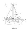
- FIG. 3B is a schematic diagram showing a single-masted monohull sailboat with fully extended first jib and a mainsail according to another embodiment of the invention.
- FIG. 3C is a schematic diagram showing a double-masted monohull sailboat with fully extended left jib according to the present invention.
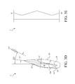
- FIG. 3D is a top view of a single-masted monohull sailboat with fully extended first jib of FIG. 3A .
- FIG. 3E is a schematic diagram illustrating a zigzagging sailing trajectory of the single-masted monohull sailboat of FIG. 3A .
- FIG. 4A is a schematic diagram showing a single-masted monohull sailboat with fully extended first jib according to another embodiment of the present invention.
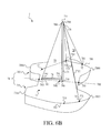
- FIG. 4B is a schematic diagram showing a single-masted monohull sailboat with fully extended first jib and a mainsail according to another embodiment of the invention..
- FIG. 4C is a top view of a single-masted monohull sailboat with fully extended first jib of FIG. 4A .
- FIG. 4D is a schematic diagram illustrating a zigzagging sailing trajectory of the single-masted monohull sailboat of FIG. 4A .
- FIG. 5A is a schematic diagram showing a single-masted catamaran with fully extended first jib according to an embodiment of the present invention.
- FIG. 5B is a schematic diagram showing a single-masted catamaran with fully extended first jib and a mainsail according to the present invention.
- FIG. 5C is a schematic diagram showing a double-masted catamaran with fully extended left jib according to the present invention.
- FIG. 5D is a top view of a single-masted catamaran with fully extended first jib of FIG. 5A .
- FIG. 5E is a schematic diagram illustrating a zigzagging sailing trajectory of the single-masted catamaran of FIG. 5A .
- FIG. 6A is a schematic diagram showing a single-masted catamaran with fully extended first jib according to another embodiment of the present invention.
- FIG. 6B is a schematic diagram showing a single-masted catamaran with fully extended first jib and a mainsail according the present invention.
- FIG. 6C is a top view of a single-masted catamaran with fully extended first jib of FIG. 6A .
- FIG. 6D is a schematic diagram illustrating a zigzagging sailing trajectory of the single-masted catamaran of FIG. 6A .
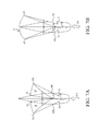
- FIG. 7A is a top view of a single-masted monohull sailboat with its two jib fully extended according to the present invention.
- FIG. 7B is a top view of a single-masted monohull sailboat using conventional spinnakers.
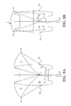
- FIG. 8A is a top view of a single-masted catamaran with its two jibs fully extended according to the present invention.
- FIG. 8B is a top view of a single-masted catamaran using conventional spinnakers.
- FIG. 3A and FIG. 4A are schematic diagrams showing a single-masted monohull sailboat with fully extended first jib and no mainsail according to two different embodiments of the present invention. It is noted that although the sailboats shown in FIG. 3A and FIG. 4A is a single-masted monohull sailboat 5, the amount of mast is not limited thereby. In the two embodiments shown in FIG. 3A and FIG.
- the single-masted monohull sailboat 5 includes: a hull 50, a mast 51, a first fixing element 52, a second fixing element 53, a first winch 54, a second winch 55, a first pulley 540, a second pulley 550, a first jib 56, a second jib 57, in which the hull 50 is further configured with a center line 500, a bow 501, a midship 502, a stem 503, a port side 504 and a starboard side 505.
- the mast 51 is configured with a first end 510 and a second end 511 at positions opposite to each other while coupling the first end 510 to the center line 500 at any position between the bow 501 and the stern 503 as the center line 500 is arranged connecting the bow 501 and the stem 503, i.e. the center line 500 is the fore-aft center line of the sailboat 5.
- the first fixing element 52 is disposed at the post side 504 of the hull 50 while the first winch 54 is disposed at a position on the left to the center line 500 of the hull 50.
- the first pulley 540 is coupled to the port side 504 of the hull 50; the first jib 56, is configured with a plurality of ends including a first end 560, a second end 561 and a third end 562 in a manner that the first end 560 is connected to the second end 511 of the mast 51, the second end 561 is connected to the first fixing element 52, and the third end 562 is connected to the first winch 54 by way of the first pulley 540.
- the second fixing element 53 is disposed at the starboard side 505 of the hull 50 while the first winch 55 is disposed at a position on the right to the center line 500 of the hull 50.
- the second pulley 550 is coupled to the starboard side 505 of the hull 50.
- the second jib 57 is configured with a plurality of ends including a first end 570, a second end 571 and a third end 572 in a manner that the first end 570 is connected to the second end 511 of the mast 51, the second end 571 is connected to the second fixing element 53, and the third end 572 is connected to the second winch 55 by way of the second pulley 550.
- the difference of the two embodiments is that: in FIG. 3A , the first end 510 of the mast 51 is disposed at a position on the center line 500 between the midship 502 and the stem 503, and in FIG. 4A , the first end 510 of the mast 51 is disposed at a position on the center line 500 between the bow 501 and the midship 502.
- the first jib 56 and the second jib 57 will not be used simultaneously unless the sailboat 5 is sailing with a tailwind, but are used alternatively and selectively according to the direction of wind. That is, when the air heading is blowing toward the sailboat 5 from its starboard side 505, the first jib 56 is expanded and used; otherwise, when the air heading is blowing toward the sailboat 5 from its port side 504, the second jib 57 is expanded and used.
- the second jib 57 can be rolled up and furled by the rig connecting the first end 570 and the second end 571 of the second jib 57 for pulling and receiving the third end 572 of the second jib 57 to a position between the first and the second ends 570, 571.
- the first jib 56 in response to the wind direction change that it is intended to expand the second jib 57, should be furled and rolled up similarly while rigging the third end 572 of the second jib 57 to the second winch 55 by way of the second pulley 550.
- FIG. 3B and FIG. 4B are schematic diagrams showing a single-masted monohull sailboat with fully extended first jib and a mainsail according to another two embodiments of the invention. It is noted that although the sailboats shown in FIG. 3B and FIG. 4B is a single-masted monohull sailboat 5, the amount of mast is not limited thereby. As shown in FIG. 3B and FIG.
- the single-masted monohull sailboat 5 includes: a hull 50, a mast 51, a first fixing element 52, a second fixing element 53, a first winch 54, a second winch 55, a first pulley 540, a second pulley 550, a first jib 56, a second jib 57, a boom 58 and a mainsail 59, in which the hull 50 is further configured with a center line 500, a bow 501, a midship 502, a stem 503, a port side 504 and a starboard side 505.
- the mast 51 is configured with a first end 510 and a second end 511 at positions opposite to each other while coupling the first end 510 to the center line 500 at any position between the bow 501 and the stem 503 as the center line 500 is arranged connecting the bow 501 and the stem 503, i.e. the center line 500 is the fore-aft center line of the sailboat 5.
- the first fixing element 52 is disposed at the post side 504 of the hull 50 while the first winch 54 is disposed at a position on the left to the center line 500 of the hull 50.
- the first pulley 540 is coupled to the port side 504 of the hull 50.
- the first jib 56 is configured with a plurality of ends including a first end 560, a second end 561 and a third end 562 in a manner that the first end 560 is connected to the second end 511 of the mast 51, the second end 561 is connected to the first fixing element 52, and the third end 562 is connected to the first winch 54 by way of the first pulley 540.
- the second fixing element 53 is disposed at the starboard side 505 of the hull 50 while the first winch 55 is disposed at a position on the right to the center line 500 of the hull 50.
- the second pulley 550 is coupled to the starboard side 505 of the hull 50.
- the second jib 57 is configured with a plurality of ends including a first end 570, a second end 571 and a third end 572 in a manner that the first end 570 is connected to the second end 511 of the mast 51, the second end 571 is connected to the second fixing element 53, and the third end 572 is connected to the second winch 55 by way of the second pulley 550.
- the difference of the two embodiments is that: in FIG. 3A , the first end 510 of the mast 51 is disposed at a position on the center line 500 between the midship 502 and the stem 503, and in FIG. 4A , the first end 510 of the mast 51 is disposed at a position on the center line 500 between the bow 501 and the midship 502.
- the first jib 56 and the second jib 57 will not be used simultaneously unless the sailboat 5 is sailing with a tailwind, but are used alternatively and selectively according to the direction of wind. That is, when the air heading is blowing toward the sailboat 5 from its starboard side 505, the first jib 56 is expanded and used. Otherwise, when the air heading is blowing toward the sailboat 5 from its port side 504, the second jib 57 is expanded and used.
- the second jib 57 can be rolled up and furled by the rig connecting the first end 570 and the second end 571 of the second jib 57 for pulling and receiving the third end 572 of the second jib 57 to a position between the first and the second ends 570, 571.
- the first jib 56 in response to the wind direction change that it is intended to expand the second jib 57, should be furled and rolled up similarly while rigging the third end 572 of the second jib 57 to the second winch 55 by way of the second pulley 550.
- the boom 58 is configured with a first end 580 and a second end 581 at positions opposite to each other while enabling the first end 580 to be coupled with the mast 51; and the mainsail 59 is configured with a plurality of ends including a first end 590, a second end 591 and a third end 592 in a manner that the first end 591 of the mainsail 59 is coupled to the second end 511 of the mast 51, the second end 591 of the mainsail 59 is coupled to the first end 580 of the boom 58, and the third end 592 of the mainsail 59 is coupled to the second end 581 of the boom 58.
- FIG. 3C is a schematic diagram showing a double-masted monohull sailboat with fully extended left jib according to the present invention.
- FIG. 3C is a schematic diagram showing a double-masted monohull sailboat with fully extended left jib according to the present invention.
- each of the mast in FIG. 3C can be rigged with a boom and a mainsail so that it is not limited thereby.
- the monohull sailboat of the present invention is different from those conventional monohull sailboat in that:
- FIG. 3E and FIG. 4D are schematic diagrams illustrating a zigzagging sailing trajectories of the single-masted monohull sailboats of FIG. 3A and FIG. 4A .
- the two single-masted monohull sailboats are sailing from a point of departure 60 to a destination 61 following different zigzagging trajectories. Comparing the sailing trajectories shown in FIG. 1C , FIG. 3E and FIG. 4D , it is noted that the voyage distance of the sailboat disclosed in the present invention is shorter than that of a conventional sailboat.
- the single-masted catamaran 7 comprises: a hull module 70, a mast 71, a first fixing element 72, a second fixing element 73, a first winch 74, a first pulley 740, a second winch 75 a second pulley 750, a first jib 76, a second jib 77.
- the hull module 70 is further configured with: a first hull 700 having a first bow 7000 and a first stem 7001; a second hull 701 having a second bow 7010 and a second stern 7011; a center line 702; a starting end 703, defined to be the frontmost point on the center line 702 where it is intersected with the hull module 70; a midship 704; a terminating end 705, defined to the rearmost point on the center line 702 where it is intersected with the hull module 70; a port side 706; and a starboard side 707; the mast 71 is configured with a first end 710 and a second end 711 at positions opposite to each other while coupling the first end 710 to the center line 700 at any position on the center line 702, as a position on the center line 702 between the midship 704 and the terminating end 705 shown in FIG.
- center line 702 is defined to be a line connecting the center between the first bow 7000 and the second bow 7010 and the center between the first stern 7001 and the second stern 7011.
- the first fixing element 72 is disposed on the port side 706 of the hull module 70; the first winch 74 is disposed at a position on the left to the center line 702 of the hull module 70; the first pulley 740 is coupled to the port side 706; the first jib 76 is configured with a plurality of ends including a first end 760, a second end 761 and a third end 762 in a manner that the first end 760 is connected to the second end 711 of the mast 71, the second end 761 is connected to the first fixing element 72, and the third end 762 is connected to the first winch 74 by way of the pulley 740.
- the second fixing element 73 is disposed on the starboard side 707 of the hull module 70.
- the second winch 75 is disposed at a position on the right to the center line 702 of the hull module 70.
- the second pulley 750 is coupled to the starboard side 707.
- the second jib 77 is configured with a plurality of ends including a first end 770, a second end 771 and a third end 772 in a manner that the first end 770 is connected to the second end 711 of the mast 71, the second end 771 is connected to the second fixing element 73, and the third end 772 is connected to the second winch 75 by way of the second pulley 750.
- the first jib 76 and the second jib 77 will not be used simultaneously unless the sailboat 7 is sailing with a tailwind, but are used alternatively and selectively according to the direction of wind. That is, when the air heading is blowing toward the sailboat 7 from its starboard side 707, the first jib 76 is expanded and used. Otherwise, when the air heading is blowing toward the sailboat 7 from its port side 706, the second jib 77 is expanded and used.
- the second jib 77 can be rolled up and furled by the rig connecting the first end 770 and the second end 771 of the second jib 77 for pulling and receiving the third end 772 of the second jib 77 to a position between the first and the second ends 770, 771.
- the first jib 76 should be furled and rolled up similarly while rigging the third end 772 of the second jib 77 to the second winch 75 by way of the second pulley 750.
- FIG. 5B and FIG. 6B are schematic diagrams showing a single-masted catamaran with fully extended first jib and a mainsail according to another two embodiments of the invention. It is noted that although the sailboats shown in FIG. 5B and FIG. 6B are single-masted catamaran 7, the amount of mast is not limited thereby. As shown in FIG. 5B and FIG.
- the single-masted catamaran 7 includes: a hull module 70, a mast 71, a first fixing element 72, a second fixing element 73, a first winch 74, a first pulley 740, a second winch 75 a second pulley 750, a first jib 76, a second jib 77. a boom 78 and a mainsail 79.
- the hull module 70 is further configured with: a first hull 700 having a first bow 7000 and a first stem 7001; a second hull 701 having a second bow 7010 and a second stern 7011; a center line 702; a starting end 703, defined to be the frontmost point on the center line 702 where it is intersected with the hull module 70; a midship 704; a terminating end 705, defined to the rearmost point on the center line 702 where it is intersected with the hull module 70; a port side 706; and a starboard side 707.
- the mast 71 is configured with a first end 710 and a second end 711 at positions opposite to each other while coupling the first end 710 to the center line 700 at any position on the center line 702, as a position on the center line 702 between the midship 704 and the terminating end 705 shown in FIG. 5B or a position on the center line 702 between the starting end 703 and the midship 704 shown in FIG. 6B , whereas the center line 702 is defined to be a line connecting the center between the first bow 7000 and the second bow 7010 and the center between the first stern 7001 and the second stern 7011.
- the first fixing element 72 is disposed on the port side 706 of the hull module 70.
- the first winch 74 is disposed at a position on the left to the center line 702 of the hull module 70.
- the first pulley 740 is coupled to the port side 706.
- the first jib 76 is configured with a plurality of ends including a first end 760, a second end 761 and a third end 762 in a manner that the first end 760 is connected to the second end 711 of the mast 71, the second end 761 is connected to the first fixing element 72, and the third end 762 is connected to the first winch 74 by way of the pulley 740.
- the second fixing element 73 is disposed on the starboard side 707 of the hull module 70.
- the second winch 75 is disposed at a position on the right to the center line 702 of the hull module 70.
- the second pulley 750 is coupled to the starboard side 707.
- the second jib 77 is configured with a plurality of ends including a first end 770, a second end 771 and a third end 772 in a manner that the first end 770 is connected to the second end 711 of the mast 71, the second end 771 is connected to the second fixing element 73, and the third end 772 is connected to the second winch 75 by way of the second pulley 750.
- the first jib 76 and the second jib 77 will not be used simultaneously unless the sailboat 7 is sailing with a tailwind, but are used alternatively and selectively according to the direction of wind. That is, when the air heading is blowing toward the sailboat 7 from its starboard side 707, the first jib 76 is expanded and used. Otherwise, when the air heading is blowing toward the sailboat 7 from its port side 706, the second jib 77 is expanded and used.
- the second jib 77 can be rolled up and furled by the rig connecting the first end 770 and the second end 771 of the second jib 77 for pulling and receiving the third end 772 of the second jib 77 to a position between the first and the second ends 770, 771.
- the first jib 76 should be furled and rolled up similarly while rigging the third end 772 of the second jib 77 to the second winch 75 by way of the second pulley 750.
- the boom 78 is configured with a first end 780 and a second end 781 at positions opposite to each other while enabling the first end 780 to be coupled with the mast 71; and the mainsail 79 is configured with a plurality of ends including a first end 790, a second end 791 and a third end 792 in a manner that the first end 791 of the mainsail 79 is coupled to the second end 711 of the mast 71, the second end 791 of the mainsail 79 is coupled to the first end 780 of the boom 78, and the third end 792 of the mainsail 79 is coupled to the second end 781 of the boom 78.
- FIG. 5C is a schematic diagram showing a double-masted catamaran with fully extended left jib according to the present invention.
- FIG. 5C is a schematic diagram showing a double-masted catamaran with fully extended left jib according to the present invention.
- each of the mast in FIG. 5C can be rigged with a boom and a mainsail so that it is not limited thereby.
- the multi-hull sailboat of the present invention is different from those conventional multi-hull sailboat in that:
- FIG. 5E and FIG. 6D are schematic diagrams illustrating a zigzagging sailing trajectories of the single-masted catamarans of FIG. 5A and FIG. 6A .
- the two single-masted catamarans are sailing from a point of departure 80 to a destination 81 following different zigzagging trajectories. Comparing the sailing trajectories shown in FIG. 2C , FIG. 5E and FIG.6D , it is noted that the voyage distance of the multi-hull sailboat disclosed in the present invention is shorter than that of a conventional multi-hull sailboat.
- FIG. 7A is a top view of a single-masted monohull sailboat with its two jibs fully extended according to the present invention. It is noted that although the sailboat in FIG. 7A is a single-masted sailboat, the amount of masts is not limited thereby. While sailing with a tail wind as the wind direction 010 indicated in FIG.
- the monohull sailboat 5 can simply release the third end 562 of its first jib 56 that is rigged to the first winch 54 and also release the third end 572 of its second jib 57 that is rigged to the second winch 55 for enabling the two jibs 56, 57 to expand and thus to be used as spinnakers.
- the single-masted monohull sailboat is configured with a mainsail, it is not limited thereby, i.e. any sailboats of the invention without mainsail still can use its jibs as spinnaker by expanding the same in the aforementioned way.
- the spinnaker 9 is rigged to the top of the mast and any two points on the left and right to the center line of the hull module, and thereby, since the monohull sailboat of the invention is configured with two fixing elements respectively on the port side and the starboard side of the hull module and two winches as well, the rigging of the spinnaker on monohull sailboat of the invention is much easier than that on any conventional sailboat.
- the monohull sailboat in FIG. 7B is a single-masted monohull sailboat, the amount of masts is not limited thereby. As shown in FIG.
- the spinnaker 9 is configured with a plurality of ends including a first end 90, a second end 91 and a third end 92. While sailing with a tail wind as the wind direction 010 indicated in FIG. 7B for example, the first end 90 of the spinnaker 9 is coupled to the mast, the second end 91 of the spinnaker 9 is rigged to the first winch 54 and the third end 92 of the spinnaker 9 is rigged to the second winch 55. On the other hand, in addition to the aforesaid connection, the second end 91 and the third end can be connected directly to the first and the second winches 54, 55. Moreover, the expanding of the left and right jibs can be enabled simultaneously with the use of spinnaker, by that the sailboat can be propelled by more wind and thus the sailing speed is increased.
- FIG. 8A is a top view of a single-masted multi-hull sailboat with its two jibs are fully extended according to the present invention.
- the multi-hull sailboat in FIG. 8A is a single-masted multi-hull sailboat, the amount of mast is not limited thereby.
- the catamaran 7 can simply release the third end 762 of its first jib 76 that is rigged to the first winch 74 and also release the third end 772 of its second jib 77 that is rigged to the second winch 75 for enabling the two jibs 76, 77 to expand and thus to be used as spinnakers.
- the single-masted catamaran is configured with a mainsail, it is not limited thereby, i.e. any multi-hull sailboats of the invention without mainsail still can use its jibs as spinnaker by expanding the same in the aforementioned way. Nevertheless, the spinnaker 9 can also be used on a multi-hull sailboat of the invention, as shown in FIG. 8B .
- the catamaran shown in FIG. 8B is a single-masted catamaran, the amount of masts is not limited thereby.
- the spinnaker 9 is configured with a plurality of ends including a first end 90, a second end 91 and a third end 92.
- the first end 90 of the spinnaker 9 is coupled to the second end 711 of the mast 71 by way of the first winch 74, the second end 91 of the spinnaker 9 is rigged to the first winch 74 and the third end 92 of the spinnaker 9 is rigged to the second winch 75.
- the second end 91 and the third end can be connected directly to the first and the second winches 74, 75.
- the expanding of the left and right jibs can be enabled simultaneously with the use of spinnaker, by that the sailboat can be propelled by more wind and thus the sailing speed is increased.
- the sailboat of the invention is designed to meet with user's demands by enabling the left and right jibs of the sailboat to operate in an alternating manner so as to enable the sailboat to be operable without the mainsail and boom, and thus not only the construction cost relating to the mainsail and boom can be save, but also the operation procedure as well as the man power for the mainsail and boom can be forgotten.
- the fixing element on the sailboat of the invention and their positions as well the voyage distance can be shortened.
- the jib on the sailboat of the invention is able to function as the rudder for forcing the sailboat to turn into windward direction automatically.
- the sailboat of the invention can simply release its left and right jibs from their corresponding fixing elements for enabling the two jibs to expand and thus to be used as spinnakers. If it is intended to use a spinnaker on a sailboat of the invention, the spinnaker 9 can be rigged and connected by the use of the two fixing elements disposed respective on the post side and starboard side thereof. Moreover, the expanding of the left and right jibs can be enabled simultaneously with the use of spinnaker, by that the sailboat can be propelled by more wind and thus the sailing speed is increased.
Landscapes
- Engineering & Computer Science (AREA)
- Life Sciences & Earth Sciences (AREA)
- Sustainable Development (AREA)
- Sustainable Energy (AREA)
- Chemical & Material Sciences (AREA)
- Combustion & Propulsion (AREA)
- Mechanical Engineering (AREA)
- Ocean & Marine Engineering (AREA)
- Jib Cranes (AREA)
- Other Liquid Machine Or Engine Such As Wave Power Use (AREA)
- Polysaccharides And Polysaccharide Derivatives (AREA)
Applications Claiming Priority (1)
| Application Number | Priority Date | Filing Date | Title |
|---|---|---|---|
| TW099123786A TWI399323B (zh) | 2010-07-20 | 2010-07-20 | 帆船 |
Publications (2)
| Publication Number | Publication Date |
|---|---|
| EP2409911A2 true EP2409911A2 (fr) | 2012-01-25 |
| EP2409911A3 EP2409911A3 (fr) | 2013-03-20 |
Family
ID=43216980
Family Applications (1)
| Application Number | Title | Priority Date | Filing Date |
|---|---|---|---|
| EP10178523A Withdrawn EP2409911A3 (fr) | 2010-07-20 | 2010-09-22 | Voilier |
Country Status (4)
| Country | Link |
|---|---|
| US (1) | US20120017816A1 (fr) |
| EP (1) | EP2409911A3 (fr) |
| JP (1) | JP2012025371A (fr) |
| TW (1) | TWI399323B (fr) |
Families Citing this family (3)
| Publication number | Priority date | Publication date | Assignee | Title |
|---|---|---|---|---|
| CN111727152B (zh) * | 2018-02-02 | 2023-02-17 | M·弗雷泽 | 帆 |
| USD992048S1 (en) * | 2021-06-08 | 2023-07-11 | Melissa & Doug, Llc | Toy boat |
| CN114475905A (zh) * | 2022-01-17 | 2022-05-13 | 哈尔滨工程大学 | 一种太阳能帆板穿浪双体远洋帆船 |
Family Cites Families (13)
| Publication number | Priority date | Publication date | Assignee | Title |
|---|---|---|---|---|
| US3223064A (en) * | 1964-02-24 | 1965-12-14 | Wilfrid G White | Sailing rig |
| US3851609A (en) * | 1972-08-21 | 1974-12-03 | L Stearn | Two groove headstay |
| US3820493A (en) * | 1972-10-26 | 1974-06-28 | J Amick | Sailboat improvements |
| US4388888A (en) * | 1981-04-24 | 1983-06-21 | Gushurst Jr Fred W | Adjustable airfoil |
| JPS598582A (ja) * | 1982-07-06 | 1984-01-17 | Yamaha Motor Co Ltd | 小型セ−リングカタマラン |
| JPS5942797U (ja) * | 1982-09-14 | 1984-03-21 | 株式会社ユ−・エム | 帆船 |
| JPS6283297A (ja) * | 1985-10-07 | 1987-04-16 | Nippon Kokan Kk <Nkk> | ジブ式帆装置 |
| JPH062188B2 (ja) * | 1988-11-02 | 1994-01-12 | スライデックス株式会社 | 水上帆走および展示に適したヨット |
| US5988086A (en) * | 1998-02-26 | 1999-11-23 | Cerebral Technologies, Inc. | Sailboat and methods |
| FR2799723B1 (fr) * | 1999-10-14 | 2002-01-04 | Beneteau | Voile d'avant du type dont le guindant coopere avec un etai, voilier comportant une telle voile, et procede d'envoi d'une telle voile |
| US20010037756A1 (en) * | 2000-02-14 | 2001-11-08 | Fink Lowell S. | Semi-elliptical sail system for wind-propelled vehicles |
| JP2003327197A (ja) * | 2002-05-09 | 2003-11-19 | Yoshiaki Okada | セーリングボート用ブーム及びリグ |
| EP1557350A1 (fr) * | 2004-01-23 | 2005-07-27 | Luigi Greppi | Bateau à voile à hautes performances avec des éléments d'aile et des voiles de sustention |
-
2010
- 2010-07-20 TW TW099123786A patent/TWI399323B/zh not_active IP Right Cessation
- 2010-09-20 US US12/885,655 patent/US20120017816A1/en not_active Abandoned
- 2010-09-22 EP EP10178523A patent/EP2409911A3/fr not_active Withdrawn
- 2010-11-26 JP JP2010263617A patent/JP2012025371A/ja active Pending
Non-Patent Citations (1)
| Title |
|---|
| None |
Also Published As
| Publication number | Publication date |
|---|---|
| JP2012025371A (ja) | 2012-02-09 |
| TW201204601A (en) | 2012-02-01 |
| TWI399323B (zh) | 2013-06-21 |
| US20120017816A1 (en) | 2012-01-26 |
| EP2409911A3 (fr) | 2013-03-20 |
Similar Documents
| Publication | Publication Date | Title |
|---|---|---|
| US20110168071A1 (en) | System and method of adjusting the location and position of the foresail on a sailboat | |
| EP3943379B1 (fr) | Gréement pour moyen nautique et moyen nautique comprenant ledit gréement | |
| CN108367802A (zh) | 分段刚性帆 | |
| US20120017816A1 (en) | Sailboat | |
| US10223325B2 (en) | Electronic device for measuring the relative force acting upon a sail | |
| CN102105352A (zh) | 特别是用于远洋货船、游艇等的帆系统 | |
| US5896825A (en) | Dual hull watercraft | |
| CN209492689U (zh) | 一种帆船的风帆设计结构 | |
| US5048442A (en) | Spinnaker handling devices | |
| CN102372080A (zh) | 帆船 | |
| US4886008A (en) | Frame spar for soft airfoils | |
| US8234991B2 (en) | Sail propulsion system | |
| US6148753A (en) | Reconfigurable foresail | |
| CN101823551A (zh) | 襟翼斜桁四角帆 | |
| CN214648886U (zh) | 一种双头运动型游艇 | |
| WO2003101822A1 (fr) | Greement de voilure de mats jumeles | |
| EP1180478A1 (fr) | Mat avec une bôme disposée à sa partie supérieure | |
| JP2014080051A (ja) | 船舶の帆装置、帆機船、及び船舶の航行方法 | |
| US20140102346A1 (en) | Structural Support Scheme for the Replacement of Trailing Portions of Sails | |
| Dedekam | Sail and rig tuning | |
| Hasler et al. | Practical junk rig: design, aerodynamics and handling | |
| US20240337243A1 (en) | Aquatic wind power generation system | |
| US4345534A (en) | Sail rigging system | |
| TW202023899A (zh) | 帆船 | |
| ITRN20110009A1 (it) | Armo per vele nautiche a scorrimento su arco |
Legal Events
| Date | Code | Title | Description |
|---|---|---|---|
| AK | Designated contracting states |
Kind code of ref document: A2 Designated state(s): AL AT BE BG CH CY CZ DE DK EE ES FI FR GB GR HR HU IE IS IT LI LT LU LV MC MK MT NL NO PL PT RO SE SI SK SM TR |
|
| AX | Request for extension of the european patent |
Extension state: BA ME RS |
|
| PUAI | Public reference made under article 153(3) epc to a published international application that has entered the european phase |
Free format text: ORIGINAL CODE: 0009012 |
|
| PUAL | Search report despatched |
Free format text: ORIGINAL CODE: 0009013 |
|
| AK | Designated contracting states |
Kind code of ref document: A3 Designated state(s): AL AT BE BG CH CY CZ DE DK EE ES FI FR GB GR HR HU IE IS IT LI LT LU LV MC MK MT NL NO PL PT RO SE SI SK SM TR |
|
| AX | Request for extension of the european patent |
Extension state: BA ME RS |
|
| RIC1 | Information provided on ipc code assigned before grant |
Ipc: B63H 9/06 20060101AFI20130208BHEP |
|
| STAA | Information on the status of an ep patent application or granted ep patent |
Free format text: STATUS: THE APPLICATION IS DEEMED TO BE WITHDRAWN |
|
| 18D | Application deemed to be withdrawn |
Effective date: 20130921 |