EP2412253A1 - Entrappmaschine, die einen Käfig umfasst - Google Patents
Entrappmaschine, die einen Käfig umfasst Download PDFInfo
- Publication number
- EP2412253A1 EP2412253A1 EP11173718A EP11173718A EP2412253A1 EP 2412253 A1 EP2412253 A1 EP 2412253A1 EP 11173718 A EP11173718 A EP 11173718A EP 11173718 A EP11173718 A EP 11173718A EP 2412253 A1 EP2412253 A1 EP 2412253A1
- Authority
- EP
- European Patent Office
- Prior art keywords
- cage
- machine according
- axis
- machine
- movement
- Prior art date
- Legal status (The legal status is an assumption and is not a legal conclusion. Google has not performed a legal analysis and makes no representation as to the accuracy of the status listed.)
- Granted
Links
Images


Classifications
-
- A—HUMAN NECESSITIES
- A23—FOODS OR FOODSTUFFS; TREATMENT THEREOF, NOT COVERED BY OTHER CLASSES
- A23N—MACHINES OR APPARATUS FOR TREATING HARVESTED FRUIT, VEGETABLES OR FLOWER BULBS IN BULK, NOT OTHERWISE PROVIDED FOR; PEELING VEGETABLES OR FRUIT IN BULK; APPARATUS FOR PREPARING ANIMAL FEEDING- STUFFS
- A23N15/00—Machines or apparatus for other treatment of fruits or vegetables for human purposes; Machines or apparatus for topping or skinning flower bulbs
- A23N15/02—Machines or apparatus for other treatment of fruits or vegetables for human purposes; Machines or apparatus for topping or skinning flower bulbs for stemming, piercing, or stripping fruit; Removing sprouts of potatoes
- A23N15/025—Machines or apparatus for other treatment of fruits or vegetables for human purposes; Machines or apparatus for topping or skinning flower bulbs for stemming, piercing, or stripping fruit; Removing sprouts of potatoes for stemming grapes
-
- A—HUMAN NECESSITIES
- A01—AGRICULTURE; FORESTRY; ANIMAL HUSBANDRY; HUNTING; TRAPPING; FISHING
- A01D—HARVESTING; MOWING
- A01D46/00—Picking of fruits, vegetables, hops, or the like; Devices for shaking trees or shrubs
- A01D46/28—Vintaging machines, i.e. grape harvesting machines
- A01D46/285—Vintaging machines, i.e. grape harvesting machines with means for separating leaves and grapes, e.g. pneumatical means like blowing or aspirating devices
-
- B—PERFORMING OPERATIONS; TRANSPORTING
- B07—SEPARATING SOLIDS FROM SOLIDS; SORTING
- B07B—SEPARATING SOLIDS FROM SOLIDS BY SIEVING, SCREENING, SIFTING OR BY USING GAS CURRENTS; SEPARATING BY OTHER DRY METHODS APPLICABLE TO BULK MATERIAL, e.g. LOOSE ARTICLES FIT TO BE HANDLED LIKE BULK MATERIAL
- B07B1/00—Sieving, screening, sifting, or sorting solid materials using networks, gratings, grids, or the like
- B07B1/18—Drum screens
- B07B1/22—Revolving drums
- B07B1/26—Revolving drums with additional axial or radial movement of the drum
-
- B—PERFORMING OPERATIONS; TRANSPORTING
- B07—SEPARATING SOLIDS FROM SOLIDS; SORTING
- B07B—SEPARATING SOLIDS FROM SOLIDS BY SIEVING, SCREENING, SIFTING OR BY USING GAS CURRENTS; SEPARATING BY OTHER DRY METHODS APPLICABLE TO BULK MATERIAL, e.g. LOOSE ARTICLES FIT TO BE HANDLED LIKE BULK MATERIAL
- B07B1/00—Sieving, screening, sifting, or sorting solid materials using networks, gratings, grids, or the like
- B07B1/28—Moving screens not otherwise provided for, e.g. swinging, reciprocating, rocking, tilting or wobbling screens
- B07B1/282—Moving screens not otherwise provided for, e.g. swinging, reciprocating, rocking, tilting or wobbling screens their jigging movement being a closed or open curvilinear path in a plane perpendicular to the plane of the screen and parrallel or transverse to the direction of conveyance
Definitions
- the present invention generally relates to de-stemming machines.
- the invention relates more particularly to a stalking machine comprising a cage formed of a tubular element open at its ends, intended to receive bunches of berries, such as grapes with their stalk or partially scraped.
- the peripheral wall of the cage has days sized to let said bays.
- the machine can be equipped with vibrating means. These vibrating means are unable to ensure only the separation of the grains of the stems because of the small amplitude of displacement of the cage resulting from the vibratory movement.
- the object of the present invention is to propose a machine whose design makes it possible to separate the berries from the stalks and to evacuate the berries out of the cage while reducing the risk of deterioration of the berries by making it unnecessary for the presence of a tree. 'stalking.
- Another object of the present invention is to provide a machine whose design allows, with the aid of a simplified mechanism, to easily and quickly separate the bays of the stalks and quickly evacuate the berries of the cage with a reduced time stay bays in the cage.
- Another object of the present invention is to provide a machine whose system of evacuation of the berries through the peripheral wall of the cage is more efficient.
- the subject of the invention is a stalking machine comprising a cage formed of a tubular element open at its ends, intended to receive bunches of berries, such as grapes and stalks, peripheral wall of the cage having days dimensioned so as to let said bays, characterized in that said machine comprises drive means in displacement of the cage in a reciprocating movement transverse to the longitudinal axis of said cage, said reciprocating movement being able to allow on the one hand, the separation of berry berries, on the other hand the expulsion of berries through the days of the peripheral wall of the cage.
- the machine according to the invention makes it possible to detach the berries from their stalk by using a shake of the cluster by swinging in a radial direction relative to the longitudinal axis of the cage and not with the aid of a tree. destemming as in the state of the art.
- the movement back and forth of the cage allows to transmit to the reciprocating bays in a radial direction to the longitudinal axis of the cage, which allows them to detach from the stalks and to be ejected to the outside of the cage through the days of the peripheral wall of said cage.
- the movement of the cage back and forth transversely to its longitudinal axis makes it possible to use the inertia of the bays to separate them from their stalk.
- the kinetic energy of the bays obtained by the movement back and forth of the cage causes them to tear off the stalk, especially when changing the direction of oscillation of the cage.
- the stalk being trapped inside the cage, in particular with the help of the retaining means as detailed below, its stroke is brutally thwarted during a change of direction of movement of the cage while the grains have acquired sufficient kinetic energy to detach from the stalk and continue their course through the days of the perimeter wall of the cage.
- the drive means in displacement of the cage are configured for, in at least one location of the length of the the cage for at least part of the training period when moving the cage a distance less than 60 mm, preferably between 60 and 160 mm, during the forward movement or the return movement of said cage.
- the means for moving the cage are configured, at least at a location along the length of the cage, to present to the cage, halfway the path traveled by the cage during its race. to go or its return stroke, a travel speed of at least 0.5 m / s, preferably between 0.5 and 4 m / s for at least part of the drive period in displacement of the cage .
- the cage has, during at least part of its drive period in displacement, corresponding to the so-called active de-stalking phase, an amplitude of movement of at least 60 mm, preferably between 60 and 160 mm and a movement speed of at least 0.5 m / s, preferably between 0.5 and 4 m / s.
- one of the ends of the cage forming the entry of introduction of the clusters and the opposite end of the cage forming the outlet of the stems, the cage is coupled to support means so that the cage has or is capable of occupying at least one position in which the entrance of the cage is located above the exit of said cage.
- said drive means in displacement of the cage are drive means at least in pivoting of the cage about an axis, distinct from the longitudinal axis of the cage, preferably outside the cage.
- the pivoting of the cage makes it possible to give a substantially curved pulse to the clusters in the cage, which favors the separation of the berries and their ejection through the days of the peripheral wall of the cage.
- the machine has at least one configuration in which the longitudinal axis of the cage forms a non-zero angle with the pivot axis of said drive means.
- the inclination of the axis of the cage relative to the pivot axis makes it possible to vary the amplitude of the transverse movements undergone by the bays along the cage between the entrance and the exit of the cage and thus of gradually increase the separation force applied to the bays with respect to the stalks during their course along the cage.
- said machine comprises means for adjusting the angle formed between the longitudinal axis of the cage and the pivot axis of said cage.
- one of the ends of the cage forming the entry of introduction of the clusters and the opposite end of the cage forming the outlet of the stems the distance between the entrance of the cage and the pivot axis of the cage is less than the distance between the exit of the cage and the pivot axis of the cage.
- said reciprocating cage driving means comprises a rotary motor and a motion transformation system coupled to said motor so as to transform the movement of the cage. motor rotation in a back and forth motion.
- said drive means comprise a shaft integral with, or integral with, the cage and of axis coinciding with said axis of pivoting of the cage, said shaft being pivotally mounted about its axis and coupled to said motion transformation system when he is present.
- said motion transformation system coupled, on the one hand, to the rotary motor and, on the other hand, to the pivot shaft integral with, or integral with, the cage, is a rod / crank type system.
- the cage is a cage mounted fixed to rotation or free to rotate about its longitudinal axis.
- the cage is devoid of means for rotating the cage about its longitudinal axis.
- the machine comprising a frame
- the cage is pivotally mounted relative to said frame to occupy different positions inclined relative to the frame.
- Adjusting the inclination of the longitudinal axis of the cage makes it possible to play on the energy to be applied to the racks to separate them from the stalks and on the work rate of the machine. Indeed, when the cage is inclined in a position close to the vertical, the bunches stay in the cage for a short time which increases the work rate. In addition, in the vertical position of the cage, the clusters are released gravity contacts with the peripheral wall of the cage, which reduces the risk of alteration of said berries and facilitates their detachment of stalks.
- the peripheral wall of the cage is formed of longitudinal bars, preferably flexible, spaced apart from each other to define the days of the peripheral wall of the cage.
- the peripheral wall of the cage can also be formed of a wall with holes.
- the cage comprises means for retaining or slowing the advance of the clusters in the cage.
- said retention or slowing means are formed by rods, also called fingers, preferably flexible, transverse to the longitudinal axis of the cage, preferably in radiating arrangement with respect to the longitudinal axis of the cage, which penetrate at least partially into said cage so as to reduce the passage section inside the cage in at least one given position along the cage.
- Such means for retaining or slowing the advance of the bunches in the cage make it possible to slow down the bunches in the cage and thus to keep them in the cage for the time of their total destemming.
- Said rods retaining or slowing means also form decompressing fingers of the clusters.
- the means for retaining or slowing the advancement of the clusters in the cage are formed by a variation of the passage section of the cage.
- the cage can thus be formed in the manner of a diabolo by two enlarged passage sections separated by a passage section of reduced dimension, the diabolo profile being optionally repeated one or more times.
- said means for driving the cage in a reciprocating motion comprise means for adjusting the amplitude of the movement of the cage back and forth.
- the subject of the invention is also a method of destemming using a stalking machine conforming to that described above, characterized in that the said method comprises, for desalting purposes, a step of driving back and forth the cage along a predetermined path during which the at least one location of its length, during the course of its forward or return stroke, it travels over at least part of the training period when the cage is moving a distance of at least 60 mm from preferably between 60 and 160 mm, and is, during its movement, driven over at least part of its trajectory at a speed of at least 0.5 m / s, preferably between 0.5 and 4 m / s.
- the invention relates to a stalking machine, or de-stemming, comprising a cage 2 formed of a tubular element 20 with 2A input and axial output 2B, intended to receive clusters berries, such as grapes with their stems. Clusters can already be partially scuffed.
- the cage 2 has a cylindrical body of circular section.
- the tubular body of the cage may be frustoconical, bent and / or variable section.
- the tubular body of the tubular element constituting the peripheral surface or peripheral wall of the cage has days dimensioned so as to allow the said bays to pass, while preventing the passage of the stalks which end up being discharged through the outlet 2B of the cage.
- said machine comprises drive means 5, 3, 6 in displacement of the cage 2 in a reciprocating movement transverse to the longitudinal axis A2 of said cage 2 to allow on the one hand, the separation of berry berries, on the other hand, the expulsion of berries through the days of the peripheral wall of the cage.
- the cage 2 is non-rotating about its longitudinal axis A2.
- Such a characteristic of displacement back and forth of the cage in a direction transverse to the longitudinal axis A2 of said cage 2 allows to transmit to the bays reciprocating in a direction radial to the axis of the cage, which allows them to detach from the stalks and to be ejected outside the cage through the days of the peripheral wall of said cage.
- the cage In the configuration of use of the machine, the cage is inclined relative to the horizontal.
- the cage 2 is coupled to support means 4 so that the inlet 2A of the cage 2 is located above the outlet 2B of said cage 2, to allow a gravity feed of the products contained in the cage .
- Said drive means 5, 3, 6 in displacement of the cage 2 are drive means at least in pivoting of the cage 2 about an axis A3, distinct from the longitudinal axis A2 of the cage 2, external preference to the cage 2.
- the bays contained in the cage are thus subject to a reciprocating movement of the pendular type, following a curved path.
- the bays are accelerated and, thanks to their inertia, detach stalks being ejected radially out of the cage 2.
- the drive means 5, 3, 6 moving the cage 2 are configured for at least, at a location of the length of the cage 2, to go to the cage 2 a distance of at least 60 mm , from preferably between 60 and 160 mm, during the forward movement or the return movement of said cage 2.
- the drive means 5, 3, 6 in displacement of the cage 2 are configured so that, at least at a location of the length of the cage 2, they are presented to the cage 2, halfway along the path traveled by the cage 2 during its outward or return stroke, a displacement speed at least equal to 0.5 m / s, preferably between 0.5 and 4 m / s.
- the longitudinal axis A2 of the cage 2 forms a preferably non-zero angle with the pivot axis A3 of said drive means 5, 3, 6.
- one of the ends of the cage 2 forming the inlet 2A of introduction of the clusters and the opposite end of the cage 2 forming exit 2B of the stems evacuation the distance between the entrance 2A of the cage 2 and the pivot axis A3 of the cage 2 is less than the distance between the output 2B of the cage 2 and the pivot axis A3 of the cage 2.
- the entrance 2A of the cage is located near the top of the balance.
- the top of the balance is located near the point of intersection between the axis A2 of the cage and the pivot axis A3 of said cage, which constitutes a neutral point of amplitude.
- the inlet 2A of the cage undergoes only a small clearance relative to its opposite end which forms the outlet 2B for evacuation of the cage, which facilitates the filling of the cage.
- the pendulum movement of the cage by pivoting the cage about an axis A3 not parallel to its axis A2 allows the bays with a connection to the low resistance cluster to detach quickly, and the bays with a connection to the cluster of greater resistance to advance along the cage and to be subjected as they move towards the exit of the cage to movements of greater amplitude.
- the transverse forces experienced by the bays due to oscillations of the cage increase as said clusters advance towards the exit of the cage. Indeed, more the clusters are close to the exit 2B of the cage, which is remote from the axis A3, plus they are subject to large amplitude displacements around said axis A3 of pivoting of the cage.
- the displacement drive means of the cage are configured to generate, at the bay a force of inertia preferably greater than 0.5 N, to ensure the separation of the array of the cluster.
- the angle between the axis A2 of the cage and the pivot axis A3 defines the difference in amplitude between the inlet 2A and the outlet 2B of the cage 2.
- Said machine also comprises adjustment means 32 for the angle formed between the longitudinal axis A2 of the cage 2 and the axis A3 of pivoting of said cage 2, which makes it possible to increase or reduce the transverse forces to which are subjected the berries, especially near the exit of the cage.
- Said drive means 5, 3, 6 of the cage 2 comprise a rotary motor 5 and a motion transformation system 6 coupled to said motor 5 so as to transform the rotational movement of the motor 5 into a movement of va-and- comes.
- Said drive means 5, 3, 6 also comprise a shaft 3 integral in rotation with the cage 2 and axis A3 coincides with said axis A3 of pivoting of the cage 2.
- Said shaft 3 is external to the cage. This shaft 3 is pivotally mounted in a bearing 43 about its axis A3 and coupled to said motion transformation system 6 as detailed below.
- the bearing 43 also carries the motor 5 at its outer peripheral wall.
- Said movement transformation system 6 is a system of type crank rod.
- said motion transformation system 6 comprises three elements for transmitting motion articulated between them and formed of two so-called end transmission elements, one coupled to the output shaft of the motor. 5, the other 62 to the pivot shaft 3, and an intermediate transmission member 61 coupled to each of said end transmission members 60, 62 at off-center positions of the respective axes of the output shaft 50 of the motor 5 and shaft 3 pivot.
- the machine comprises support means 4 of said pivot shaft 3 formed of a base 42 intended to be positioned preferably on the ground, a support arm 40 coupled to said base 42 and a bearing 43 integral with said support arm 40 to receive the shaft 3 pivot.
- Said machine also comprises means 41 for adjusting the inclination of the support arm 40, and therefore of said pivot shaft 3, with respect to said base 42.
- Such inclination adjusting means 41 allow, possibly in cooperation with the means of tilt adjustment 32 between the axis A2 of the cage and the axis A3 of pivoting of the cage, to vary the inclination of the cage between a horizontal position and a vertical position.
- the cage 2 is equipped, as detailed below, retaining means or slowing 22 of the advancement of the bays along the cage towards the exhaust outlet .
- the cage has a shape inscribed in a cylinder and has a circular section.
- the peripheral wall of the cage 2 may be formed of longitudinal bars spaced from each other to define the days of the peripheral wall of the cage 2. Said bars are formed by rods, preferably flexible, stretched between the ends of the cage.
- the cage 2 comprises means for retaining or slowing down the advance of the clusters in the cage.
- said retention or slowing means are formed by rods 22, preferably flexible, transverse to the longitudinal axis A2 of the cage 2, preferably in a radiating arrangement with respect to the axis A2. longitudinal of the cage 2. Said rods penetrate at least partially into said cage 2 so as to reduce the passage section inside the cage 2 in at least one given position along the cage.
- Said rods remain spaced from the axis A2 of the cage to leave free passage space for the crawls along the cage while slowing down their advance by gripping them at the areas close to the peripheral wall where are located said rods.
- Said rods are also inclined at an acute angle with respect to the axis A2 of the cage so as to define a funnel whose entrance of larger opening is located on the entrance side of the cage.
- said retention or retarding means 22 comprise two series of rods forming two funnels arranged in two distinct positions along the cage, one substantially halfway between the inlet and the outlet of the cage and the other near the exit of the cage.
- the cage comprises at least one portion which has a profile, said diabolo formed of two enlarged passage sections separated by a passage section of reduced size which forms said retaining means or slowing down.
- Said drive means 5, 3, 6 of the cage 2 comprise means adjusting the amplitude of the reciprocating movement of the cage 2.
- said pivoting amplitude adjustment means are formed by means for adjusting the coupling position of the transmission element. intermediate 61 along one 60 and / or the other 62 end transmission member.
- said amplitude adjusting means are formed by a coupling position adjusting system of the intermediate transmission member 61 along the end transmission member 62 integral with the pivot shaft 3.
- Said system The adjusting device is composed of a through groove formed along the transmission element 62 and a screw system for fixing the position of the transmission element 61 along the slot of the transmission element 62. while allowing articulation between said transmission elements 61, 62.
- said amplitude adjusting means is formed by a coupling position adjusting system of the intermediate transmission member 61 along the end transmission member 60 integral with the engine output shaft 50 5.
- Said adjustment system is composed of a through groove 601 formed along the transmission element 60 and a screw system for fixing the position of the transmission element 61 along the slot of the transmission element 60 while allowing articulation between said transmission elements 61, 60.
- the greater the position of articulation between said transmission elements 61, 60 is away from the axis of rotation of the motor 5, the greater the amplitude of the reciprocating movement of the cage 2 is important.
- the frequency of the reciprocating movement or swinging of the cage 2 depends on the speed of rotation of the motor 5.
- the machine comprises means for adjusting the speed of rotation of the motor, to adjust the stirring frequency of the cage.
- said drive means 5, 3, 6 in displacement of the cage 2 to be driving means for driving. displacement at least by translation of the cage 2 in a back and forth motion along an axis transverse to the axis of the cage 2.
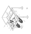
- the machine comprises several cages movable back and forth transversely to their longitudinal axis by means of at least partially common drive means.
- said machine comprises two cages 2 arranged in parallel.
- Each of the cages 2 is integral in rotation with a pivot shaft 3 as detailed above.
- Said pivot shafts are arranged parallel to each other and coupled to the same motor 5 by means of motion transformation means 6 as described above which make it possible to transform the rotational movement of the motor 5 into a reciprocating pivoting movement of each pivot shaft 3 to oscillate each cage 2 about the axis of the corresponding pivot shaft 3.
Landscapes
- Life Sciences & Earth Sciences (AREA)
- Environmental Sciences (AREA)
- Chemical & Material Sciences (AREA)
- Engineering & Computer Science (AREA)
- Food Science & Technology (AREA)
- Polymers & Plastics (AREA)
- Apparatuses For Bulk Treatment Of Fruits And Vegetables And Apparatuses For Preparing Feeds (AREA)
Priority Applications (2)
| Application Number | Priority Date | Filing Date | Title |
|---|---|---|---|
| SI201130010T SI2412253T1 (sl) | 2010-07-28 | 2011-07-13 | Naprava za odstranjevanje stebel s kletko |
| EP12159049.1A EP2468114B1 (de) | 2010-07-28 | 2011-07-13 | Entrappmaschine, die einen Korb umfasst |
Applications Claiming Priority (1)
| Application Number | Priority Date | Filing Date | Title |
|---|---|---|---|
| FR1056194A FR2963209B1 (fr) | 2010-07-28 | 2010-07-28 | Machine d'egrappage comprenant une cage |
Related Child Applications (2)
| Application Number | Title | Priority Date | Filing Date |
|---|---|---|---|
| EP12159049.1A Division-Into EP2468114B1 (de) | 2010-07-28 | 2011-07-13 | Entrappmaschine, die einen Korb umfasst |
| EP12159049.1A Division EP2468114B1 (de) | 2010-07-28 | 2011-07-13 | Entrappmaschine, die einen Korb umfasst |
Publications (2)
| Publication Number | Publication Date |
|---|---|
| EP2412253A1 true EP2412253A1 (de) | 2012-02-01 |
| EP2412253B1 EP2412253B1 (de) | 2012-09-26 |
Family
ID=43837970
Family Applications (2)
| Application Number | Title | Priority Date | Filing Date |
|---|---|---|---|
| EP12159049.1A Active EP2468114B1 (de) | 2010-07-28 | 2011-07-13 | Entrappmaschine, die einen Korb umfasst |
| EP11173718A Active EP2412253B1 (de) | 2010-07-28 | 2011-07-13 | Entrappmaschine, die einen Käfig umfasst |
Family Applications Before (1)
| Application Number | Title | Priority Date | Filing Date |
|---|---|---|---|
| EP12159049.1A Active EP2468114B1 (de) | 2010-07-28 | 2011-07-13 | Entrappmaschine, die einen Korb umfasst |
Country Status (4)
| Country | Link |
|---|---|
| EP (2) | EP2468114B1 (de) |
| ES (2) | ES2396315T3 (de) |
| FR (1) | FR2963209B1 (de) |
| SI (2) | SI2412253T1 (de) |
Cited By (3)
| Publication number | Priority date | Publication date | Assignee | Title |
|---|---|---|---|---|
| JP5914792B1 (ja) * | 2015-04-09 | 2016-05-11 | 株式会社エクセム | 収穫物の処理装置及び処理方法 |
| EP3132694B1 (de) | 2015-08-20 | 2017-08-23 | C.M.A. S.N.C. di Minnicucci Tommaso Giuseppe & C. | Auswahlmaschine zur trennung von obst von an dem obst haftenden fremdkörpern |
| EP3794930A1 (de) * | 2019-09-19 | 2021-03-24 | CNH Industrial France S.A.S. | Abbeermaschine für obsterntemaschine |
Families Citing this family (5)
| Publication number | Priority date | Publication date | Assignee | Title |
|---|---|---|---|---|
| RU2711294C1 (ru) * | 2019-03-06 | 2020-01-16 | Александр Григорьевич Жихарев | Комбайн для отделения некондиционных ягод винограда и посторонних включений |
| FR3112060A1 (fr) | 2020-07-01 | 2022-01-07 | Bucher Vaslin | installation de traitement de produits récoltés, notamment de fruits récoltés tels que de la vendange |
| FR3135879B1 (fr) | 2022-05-24 | 2024-04-19 | Bucher Vaslin | Procédé et une installation de traitement de fruits récoltés en grappe, en particulier de raisins |
| FR3135878B1 (fr) | 2022-05-24 | 2025-02-21 | Bucher Vaslin | Procédé et installation de traitement de fruits récoltés en grappe, en particulier de raisins |
| ES2995890T3 (en) | 2022-05-24 | 2025-02-11 | Bucher Vaslin | Method and installation for processing fruit harvested in clusters, in particular grapes |
Citations (8)
| Publication number | Priority date | Publication date | Assignee | Title |
|---|---|---|---|---|
| US1409802A (en) * | 1918-02-04 | 1922-03-14 | William E Urschel | Apparatus for and process of stemming fruit |
| FR1033642A (fr) * | 1950-01-31 | 1953-07-13 | Standard Canners And Packers L | Procédé et appareil pour égrainer les fruits en grappes |
| US3587686A (en) * | 1969-05-26 | 1971-06-28 | Mclauchlan Co Inc Ab | Device for stemming certain berries and fruits |
| US4029005A (en) * | 1974-01-23 | 1977-06-14 | Derderian Edward J | Stemming machine |
| DE8808236U1 (de) * | 1988-06-27 | 1988-09-08 | Siebtechnik GmbH, 4330 Mülheim | Trommelsieb |
| FR2651694A1 (fr) | 1989-09-14 | 1991-03-15 | Mvs Motoviticulture Saumuroise | Dispositif pour trier des produits juteux et collants. |
| DE20310936U1 (de) * | 2003-07-16 | 2003-09-18 | Armbruster, Hermann, 74363 Güglingen | Abbeermaschine |
| FR2862493A1 (fr) * | 2003-11-24 | 2005-05-27 | Gregoire | Egrappoir comportant un rotor rotatif et vibrant |
-
2010
- 2010-07-28 FR FR1056194A patent/FR2963209B1/fr active Active
-
2011
- 2011-07-13 SI SI201130010T patent/SI2412253T1/sl unknown
- 2011-07-13 EP EP12159049.1A patent/EP2468114B1/de active Active
- 2011-07-13 ES ES11173718T patent/ES2396315T3/es active Active
- 2011-07-13 ES ES12159049.1T patent/ES2554609T3/es active Active
- 2011-07-13 EP EP11173718A patent/EP2412253B1/de active Active
- 2011-07-13 SI SI201130674T patent/SI2468114T1/sl unknown
Patent Citations (8)
| Publication number | Priority date | Publication date | Assignee | Title |
|---|---|---|---|---|
| US1409802A (en) * | 1918-02-04 | 1922-03-14 | William E Urschel | Apparatus for and process of stemming fruit |
| FR1033642A (fr) * | 1950-01-31 | 1953-07-13 | Standard Canners And Packers L | Procédé et appareil pour égrainer les fruits en grappes |
| US3587686A (en) * | 1969-05-26 | 1971-06-28 | Mclauchlan Co Inc Ab | Device for stemming certain berries and fruits |
| US4029005A (en) * | 1974-01-23 | 1977-06-14 | Derderian Edward J | Stemming machine |
| DE8808236U1 (de) * | 1988-06-27 | 1988-09-08 | Siebtechnik GmbH, 4330 Mülheim | Trommelsieb |
| FR2651694A1 (fr) | 1989-09-14 | 1991-03-15 | Mvs Motoviticulture Saumuroise | Dispositif pour trier des produits juteux et collants. |
| DE20310936U1 (de) * | 2003-07-16 | 2003-09-18 | Armbruster, Hermann, 74363 Güglingen | Abbeermaschine |
| FR2862493A1 (fr) * | 2003-11-24 | 2005-05-27 | Gregoire | Egrappoir comportant un rotor rotatif et vibrant |
Cited By (5)
| Publication number | Priority date | Publication date | Assignee | Title |
|---|---|---|---|---|
| JP5914792B1 (ja) * | 2015-04-09 | 2016-05-11 | 株式会社エクセム | 収穫物の処理装置及び処理方法 |
| EP3132694B1 (de) | 2015-08-20 | 2017-08-23 | C.M.A. S.N.C. di Minnicucci Tommaso Giuseppe & C. | Auswahlmaschine zur trennung von obst von an dem obst haftenden fremdkörpern |
| EP3794930A1 (de) * | 2019-09-19 | 2021-03-24 | CNH Industrial France S.A.S. | Abbeermaschine für obsterntemaschine |
| WO2021053147A1 (en) * | 2019-09-19 | 2021-03-25 | Cnh Industrial France S.A.S. | Destemmer for a fruit harvester |
| US12557832B2 (en) | 2019-09-19 | 2026-02-24 | Cnh Industrial America Llc | Destemmer for a fruit harvester |
Also Published As
| Publication number | Publication date |
|---|---|
| FR2963209B1 (fr) | 2015-04-10 |
| EP2412253B1 (de) | 2012-09-26 |
| EP2468114A1 (de) | 2012-06-27 |
| ES2396315T3 (es) | 2013-02-20 |
| ES2554609T3 (es) | 2015-12-22 |
| EP2468114B1 (de) | 2015-09-02 |
| SI2412253T1 (sl) | 2013-02-28 |
| FR2963209A1 (fr) | 2012-02-03 |
| SI2468114T1 (sl) | 2016-02-29 |
Similar Documents
| Publication | Publication Date | Title |
|---|---|---|
| EP2468114B1 (de) | Entrappmaschine, die einen Korb umfasst | |
| EP2149291B1 (de) | Beeren-Erntemaschine, insbesondere Weintrauben-Erntemaschine, die mit einem Schüttelsystem ausgestattet ist, und megatronische Schüttelsteuerung dieses Systems | |
| EP2030514B1 (de) | Abbeermaschine mit hin- und hergehenden oszillierenden Bewegungen | |
| EP2149290B1 (de) | Schüttler mit regulierbarer Stärke für Erntemaschinen und Erntemaschinen, bei denen solche Schüttler zum Einsatz kommen | |
| FR2957223A1 (fr) | Faneuse a fonctions d'andainage et d'epandage a decalage transversal | |
| EP0364365B1 (de) | Korn-Trennungsvorrichtung für Mähdrescher | |
| EP2140751B1 (de) | Vorrichtung und System zur Obsternte durch kanalisiertes Blasen im Kreis | |
| EP3794961B1 (de) | Stationäre abbeermaschine für eine weinherstellungsanlage | |
| EP2896289B1 (de) | Durchbrochene Drehtrommel mit Anziehungskraft zum Entlauben von Pflanzen, und Entlaubungsköpfe, die mit einer solchen Trommel ausgestattet sind | |
| FR2616630A1 (fr) | Egrappoir separateur-trieur de vendange | |
| EP3494803A1 (de) | Maschine zum entrappen von trauben | |
| EP2883444B1 (de) | Entlaubungsvorrichtung mit doppeltem Luftstrom | |
| WO2018220465A1 (fr) | Appareil destiné à recueillir les pistils et les stigmates de fleurs de crocus à partir de fleur de crocus | |
| EP0013442B1 (de) | Verteiler von quasi-sphärischen Gegenständen | |
| FR2892657A1 (fr) | Dispositif de compactage d'un materiau et/ou pour separer un solide et un liquide, et procede correspondant | |
| EP3612016B1 (de) | Schwadbelüftervorrichtung und mit solch einer vorrichtung ausgestattete landwirtschaftliche maschine | |
| FR2742301A1 (fr) | Dispositif de fauchage et de convoyage pour un produit recolte muni de tiges | |
| FR2862493A1 (fr) | Egrappoir comportant un rotor rotatif et vibrant | |
| EP4282284B1 (de) | Verfahren und anlage zur behandlung von trauben von geernteten früchten, insbesondere weintrauben | |
| EP0543688B1 (de) | Silofutterschneider | |
| FR3135878A1 (fr) | Procédé et installation de traitement de fruits récoltés en grappe, en particulier de raisins | |
| FR2840775A1 (fr) | Erafloir ou egrappoir a arbre rotatif | |
| FR3099871A1 (fr) | Dispositif de retournement de pates alimentaires dans une installation de cuisson par friture | |
| FR2994054A1 (fr) | Dispositif de recuperation de menue-paille | |
| FR2551315A1 (fr) | Procede et dispositif pour manutentionner des produits recoltes mecaniquement en eliminant les dechets legers et machine comportant ces dispositifs |
Legal Events
| Date | Code | Title | Description |
|---|---|---|---|
| AK | Designated contracting states |
Kind code of ref document: A1 Designated state(s): AL AT BE BG CH CY CZ DE DK EE ES FI FR GB GR HR HU IE IS IT LI LT LU LV MC MK MT NL NO PL PT RO RS SE SI SK SM TR |
|
| AX | Request for extension of the european patent |
Extension state: BA ME |
|
| PUAI | Public reference made under article 153(3) epc to a published international application that has entered the european phase |
Free format text: ORIGINAL CODE: 0009012 |
|
| 17P | Request for examination filed |
Effective date: 20120209 |
|
| GRAP | Despatch of communication of intention to grant a patent |
Free format text: ORIGINAL CODE: EPIDOSNIGR1 |
|
| GRAS | Grant fee paid |
Free format text: ORIGINAL CODE: EPIDOSNIGR3 |
|
| GRAA | (expected) grant |
Free format text: ORIGINAL CODE: 0009210 |
|
| AK | Designated contracting states |
Kind code of ref document: B1 Designated state(s): AL AT BE BG CH CY CZ DE DK EE ES FI FR GB GR HR HU IE IS IT LI LT LU LV MC MK MT NL NO PL PT RO RS SE SI SK SM TR |
|
| REG | Reference to a national code |
Ref country code: GB Ref legal event code: FG4D Free format text: NOT ENGLISH |
|
| REG | Reference to a national code |
Ref country code: CH Ref legal event code: EP |
|
| REG | Reference to a national code |
Ref country code: AT Ref legal event code: REF Ref document number: 576584 Country of ref document: AT Kind code of ref document: T Effective date: 20121015 |
|
| REG | Reference to a national code |
Ref country code: IE Ref legal event code: FG4D Free format text: LANGUAGE OF EP DOCUMENT: FRENCH |
|
| REG | Reference to a national code |
Ref country code: DE Ref legal event code: R096 Ref document number: 602011000271 Country of ref document: DE Effective date: 20121122 |
|
| PG25 | Lapsed in a contracting state [announced via postgrant information from national office to epo] |
Ref country code: HR Free format text: LAPSE BECAUSE OF FAILURE TO SUBMIT A TRANSLATION OF THE DESCRIPTION OR TO PAY THE FEE WITHIN THE PRESCRIBED TIME-LIMIT Effective date: 20120926 Ref country code: FI Free format text: LAPSE BECAUSE OF FAILURE TO SUBMIT A TRANSLATION OF THE DESCRIPTION OR TO PAY THE FEE WITHIN THE PRESCRIBED TIME-LIMIT Effective date: 20120926 Ref country code: LT Free format text: LAPSE BECAUSE OF FAILURE TO SUBMIT A TRANSLATION OF THE DESCRIPTION OR TO PAY THE FEE WITHIN THE PRESCRIBED TIME-LIMIT Effective date: 20120926 Ref country code: NO Free format text: LAPSE BECAUSE OF FAILURE TO SUBMIT A TRANSLATION OF THE DESCRIPTION OR TO PAY THE FEE WITHIN THE PRESCRIBED TIME-LIMIT Effective date: 20121226 |
|
| REG | Reference to a national code |
Ref country code: ES Ref legal event code: FG2A Ref document number: 2396315 Country of ref document: ES Kind code of ref document: T3 Effective date: 20130220 |
|
| REG | Reference to a national code |
Ref country code: LT Ref legal event code: MG4D Effective date: 20120926 |
|
| REG | Reference to a national code |
Ref country code: NL Ref legal event code: VDEP Effective date: 20120926 |
|
| PG25 | Lapsed in a contracting state [announced via postgrant information from national office to epo] |
Ref country code: SE Free format text: LAPSE BECAUSE OF FAILURE TO SUBMIT A TRANSLATION OF THE DESCRIPTION OR TO PAY THE FEE WITHIN THE PRESCRIBED TIME-LIMIT Effective date: 20120926 Ref country code: LV Free format text: LAPSE BECAUSE OF FAILURE TO SUBMIT A TRANSLATION OF THE DESCRIPTION OR TO PAY THE FEE WITHIN THE PRESCRIBED TIME-LIMIT Effective date: 20120926 Ref country code: GR Free format text: LAPSE BECAUSE OF FAILURE TO SUBMIT A TRANSLATION OF THE DESCRIPTION OR TO PAY THE FEE WITHIN THE PRESCRIBED TIME-LIMIT Effective date: 20121227 |
|
| PG25 | Lapsed in a contracting state [announced via postgrant information from national office to epo] |
Ref country code: CZ Free format text: LAPSE BECAUSE OF FAILURE TO SUBMIT A TRANSLATION OF THE DESCRIPTION OR TO PAY THE FEE WITHIN THE PRESCRIBED TIME-LIMIT Effective date: 20120926 Ref country code: NL Free format text: LAPSE BECAUSE OF FAILURE TO SUBMIT A TRANSLATION OF THE DESCRIPTION OR TO PAY THE FEE WITHIN THE PRESCRIBED TIME-LIMIT Effective date: 20120926 Ref country code: IS Free format text: LAPSE BECAUSE OF FAILURE TO SUBMIT A TRANSLATION OF THE DESCRIPTION OR TO PAY THE FEE WITHIN THE PRESCRIBED TIME-LIMIT Effective date: 20130126 Ref country code: EE Free format text: LAPSE BECAUSE OF FAILURE TO SUBMIT A TRANSLATION OF THE DESCRIPTION OR TO PAY THE FEE WITHIN THE PRESCRIBED TIME-LIMIT Effective date: 20120926 Ref country code: RO Free format text: LAPSE BECAUSE OF FAILURE TO SUBMIT A TRANSLATION OF THE DESCRIPTION OR TO PAY THE FEE WITHIN THE PRESCRIBED TIME-LIMIT Effective date: 20120926 |
|
| PG25 | Lapsed in a contracting state [announced via postgrant information from national office to epo] |
Ref country code: PL Free format text: LAPSE BECAUSE OF FAILURE TO SUBMIT A TRANSLATION OF THE DESCRIPTION OR TO PAY THE FEE WITHIN THE PRESCRIBED TIME-LIMIT Effective date: 20120926 Ref country code: SK Free format text: LAPSE BECAUSE OF FAILURE TO SUBMIT A TRANSLATION OF THE DESCRIPTION OR TO PAY THE FEE WITHIN THE PRESCRIBED TIME-LIMIT Effective date: 20120926 Ref country code: PT Free format text: LAPSE BECAUSE OF FAILURE TO SUBMIT A TRANSLATION OF THE DESCRIPTION OR TO PAY THE FEE WITHIN THE PRESCRIBED TIME-LIMIT Effective date: 20130128 |
|
| PG25 | Lapsed in a contracting state [announced via postgrant information from national office to epo] |
Ref country code: RS Free format text: LAPSE BECAUSE OF FAILURE TO SUBMIT A TRANSLATION OF THE DESCRIPTION OR TO PAY THE FEE WITHIN THE PRESCRIBED TIME-LIMIT Effective date: 20120926 Ref country code: DK Free format text: LAPSE BECAUSE OF FAILURE TO SUBMIT A TRANSLATION OF THE DESCRIPTION OR TO PAY THE FEE WITHIN THE PRESCRIBED TIME-LIMIT Effective date: 20120926 |
|
| PLBE | No opposition filed within time limit |
Free format text: ORIGINAL CODE: 0009261 |
|
| STAA | Information on the status of an ep patent application or granted ep patent |
Free format text: STATUS: NO OPPOSITION FILED WITHIN TIME LIMIT |
|
| 26N | No opposition filed |
Effective date: 20130627 |
|
| REG | Reference to a national code |
Ref country code: DE Ref legal event code: R097 Ref document number: 602011000271 Country of ref document: DE Effective date: 20130627 |
|
| PG25 | Lapsed in a contracting state [announced via postgrant information from national office to epo] |
Ref country code: CY Free format text: LAPSE BECAUSE OF FAILURE TO SUBMIT A TRANSLATION OF THE DESCRIPTION OR TO PAY THE FEE WITHIN THE PRESCRIBED TIME-LIMIT Effective date: 20120926 |
|
| BERE | Be: lapsed |
Owner name: BUCHER VASLIN Effective date: 20130731 |
|
| PG25 | Lapsed in a contracting state [announced via postgrant information from national office to epo] |
Ref country code: MC Free format text: LAPSE BECAUSE OF FAILURE TO SUBMIT A TRANSLATION OF THE DESCRIPTION OR TO PAY THE FEE WITHIN THE PRESCRIBED TIME-LIMIT Effective date: 20120926 |
|
| REG | Reference to a national code |
Ref country code: IE Ref legal event code: MM4A |
|
| PG25 | Lapsed in a contracting state [announced via postgrant information from national office to epo] |
Ref country code: BE Free format text: LAPSE BECAUSE OF NON-PAYMENT OF DUE FEES Effective date: 20130731 |
|
| PG25 | Lapsed in a contracting state [announced via postgrant information from national office to epo] |
Ref country code: IE Free format text: LAPSE BECAUSE OF NON-PAYMENT OF DUE FEES Effective date: 20130713 |
|
| REG | Reference to a national code |
Ref country code: CH Ref legal event code: PL |
|
| PG25 | Lapsed in a contracting state [announced via postgrant information from national office to epo] |
Ref country code: CH Free format text: LAPSE BECAUSE OF NON-PAYMENT OF DUE FEES Effective date: 20140731 Ref country code: LI Free format text: LAPSE BECAUSE OF NON-PAYMENT OF DUE FEES Effective date: 20140731 |
|
| PG25 | Lapsed in a contracting state [announced via postgrant information from national office to epo] |
Ref country code: SM Free format text: LAPSE BECAUSE OF FAILURE TO SUBMIT A TRANSLATION OF THE DESCRIPTION OR TO PAY THE FEE WITHIN THE PRESCRIBED TIME-LIMIT Effective date: 20120926 |
|
| PG25 | Lapsed in a contracting state [announced via postgrant information from national office to epo] |
Ref country code: TR Free format text: LAPSE BECAUSE OF FAILURE TO SUBMIT A TRANSLATION OF THE DESCRIPTION OR TO PAY THE FEE WITHIN THE PRESCRIBED TIME-LIMIT Effective date: 20120926 Ref country code: MT Free format text: LAPSE BECAUSE OF FAILURE TO SUBMIT A TRANSLATION OF THE DESCRIPTION OR TO PAY THE FEE WITHIN THE PRESCRIBED TIME-LIMIT Effective date: 20120926 |
|
| PG25 | Lapsed in a contracting state [announced via postgrant information from national office to epo] |
Ref country code: HU Free format text: LAPSE BECAUSE OF FAILURE TO SUBMIT A TRANSLATION OF THE DESCRIPTION OR TO PAY THE FEE WITHIN THE PRESCRIBED TIME-LIMIT; INVALID AB INITIO Effective date: 20110713 Ref country code: MK Free format text: LAPSE BECAUSE OF FAILURE TO SUBMIT A TRANSLATION OF THE DESCRIPTION OR TO PAY THE FEE WITHIN THE PRESCRIBED TIME-LIMIT Effective date: 20120926 Ref country code: LU Free format text: LAPSE BECAUSE OF NON-PAYMENT OF DUE FEES Effective date: 20130713 |
|
| GBPC | Gb: european patent ceased through non-payment of renewal fee |
Effective date: 20150713 |
|
| PG25 | Lapsed in a contracting state [announced via postgrant information from national office to epo] |
Ref country code: GB Free format text: LAPSE BECAUSE OF NON-PAYMENT OF DUE FEES Effective date: 20150713 |
|
| REG | Reference to a national code |
Ref country code: FR Ref legal event code: PLFP Year of fee payment: 6 |
|
| REG | Reference to a national code |
Ref country code: FR Ref legal event code: PLFP Year of fee payment: 7 |
|
| REG | Reference to a national code |
Ref country code: FR Ref legal event code: PLFP Year of fee payment: 8 |
|
| REG | Reference to a national code |
Ref country code: FR Ref legal event code: CL Name of requester: CMA, IT Effective date: 20180824 |
|
| PG25 | Lapsed in a contracting state [announced via postgrant information from national office to epo] |
Ref country code: AL Free format text: LAPSE BECAUSE OF FAILURE TO SUBMIT A TRANSLATION OF THE DESCRIPTION OR TO PAY THE FEE WITHIN THE PRESCRIBED TIME-LIMIT Effective date: 20120926 |
|
| P01 | Opt-out of the competence of the unified patent court (upc) registered |
Effective date: 20230621 |
|
| REG | Reference to a national code |
Ref country code: DE Ref legal event code: R082 Ref document number: 602011000271 Country of ref document: DE Representative=s name: GLAWE DELFS MOLL PARTNERSCHAFT MBB VON PATENT-, DE Ref country code: DE Ref legal event code: R082 Ref document number: 602011000271 Country of ref document: DE Representative=s name: GLAWE DELFS MOLL PARTGMBB, DE |
|
| PGFP | Annual fee paid to national office [announced via postgrant information from national office to epo] |
Ref country code: SI Payment date: 20250711 Year of fee payment: 15 |
|
| PGFP | Annual fee paid to national office [announced via postgrant information from national office to epo] |
Ref country code: ES Payment date: 20250826 Year of fee payment: 15 |
|
| PGFP | Annual fee paid to national office [announced via postgrant information from national office to epo] |
Ref country code: DE Payment date: 20250722 Year of fee payment: 15 |
|
| PGFP | Annual fee paid to national office [announced via postgrant information from national office to epo] |
Ref country code: IT Payment date: 20250724 Year of fee payment: 15 |
|
| PGFP | Annual fee paid to national office [announced via postgrant information from national office to epo] |
Ref country code: BG Payment date: 20250722 Year of fee payment: 15 |
|
| PGFP | Annual fee paid to national office [announced via postgrant information from national office to epo] |
Ref country code: FR Payment date: 20250725 Year of fee payment: 15 Ref country code: AT Payment date: 20250722 Year of fee payment: 15 |