EP2413148A2 - Circuit de mesure de la résistance d'isolement non influencé par la tension de batterie - Google Patents
Circuit de mesure de la résistance d'isolement non influencé par la tension de batterie Download PDFInfo
- Publication number
- EP2413148A2 EP2413148A2 EP10756344A EP10756344A EP2413148A2 EP 2413148 A2 EP2413148 A2 EP 2413148A2 EP 10756344 A EP10756344 A EP 10756344A EP 10756344 A EP10756344 A EP 10756344A EP 2413148 A2 EP2413148 A2 EP 2413148A2
- Authority
- EP
- European Patent Office
- Prior art keywords
- voltage
- battery
- insulation resistance
- riso
- source
- Prior art date
- Legal status (The legal status is an assumption and is not a legal conclusion. Google has not performed a legal analysis and makes no representation as to the accuracy of the status listed.)
- Granted
Links
Images
Classifications
-
- G—PHYSICS
- G01—MEASURING; TESTING
- G01R—MEASURING ELECTRIC VARIABLES; MEASURING MAGNETIC VARIABLES
- G01R27/00—Arrangements for measuring resistance, reactance, impedance, or electric characteristics derived therefrom
- G01R27/02—Measuring real or complex resistance, reactance, impedance, or other two-pole characteristics derived therefrom, e.g. time constant
- G01R27/08—Measuring resistance by measuring both voltage and current
-
- G—PHYSICS
- G01—MEASURING; TESTING
- G01R—MEASURING ELECTRIC VARIABLES; MEASURING MAGNETIC VARIABLES
- G01R27/00—Arrangements for measuring resistance, reactance, impedance, or electric characteristics derived therefrom
- G01R27/02—Measuring real or complex resistance, reactance, impedance, or other two-pole characteristics derived therefrom, e.g. time constant
- G01R27/16—Measuring impedance of element or network through which a current is passing from another source, e.g. cable, power line
-
- G—PHYSICS
- G01—MEASURING; TESTING
- G01R—MEASURING ELECTRIC VARIABLES; MEASURING MAGNETIC VARIABLES
- G01R31/00—Arrangements for testing electric properties; Arrangements for locating electric faults; Arrangements for electrical testing characterised by what is being tested not provided for elsewhere
- G01R31/12—Testing dielectric strength or breakdown voltage ; Testing or monitoring effectiveness or level of insulation, e.g. of a cable or of an apparatus, for example using partial discharge measurements; Electrostatic testing
-
- G—PHYSICS
- G01—MEASURING; TESTING
- G01R—MEASURING ELECTRIC VARIABLES; MEASURING MAGNETIC VARIABLES
- G01R27/00—Arrangements for measuring resistance, reactance, impedance, or electric characteristics derived therefrom
- G01R27/02—Measuring real or complex resistance, reactance, impedance, or other two-pole characteristics derived therefrom, e.g. time constant
- G01R27/025—Measuring very high resistances, e.g. isolation resistances, i.e. megohm-meters
-
- G—PHYSICS
- G01—MEASURING; TESTING
- G01R—MEASURING ELECTRIC VARIABLES; MEASURING MAGNETIC VARIABLES
- G01R31/00—Arrangements for testing electric properties; Arrangements for locating electric faults; Arrangements for electrical testing characterised by what is being tested not provided for elsewhere
- G01R31/36—Arrangements for testing, measuring or monitoring the electrical condition of accumulators or electric batteries, e.g. capacity or state of charge [SoC]
- G01R31/382—Arrangements for monitoring battery or accumulator variables, e.g. SoC
-
- G—PHYSICS
- G01—MEASURING; TESTING
- G01R—MEASURING ELECTRIC VARIABLES; MEASURING MAGNETIC VARIABLES
- G01R31/00—Arrangements for testing electric properties; Arrangements for locating electric faults; Arrangements for electrical testing characterised by what is being tested not provided for elsewhere
- G01R31/36—Arrangements for testing, measuring or monitoring the electrical condition of accumulators or electric batteries, e.g. capacity or state of charge [SoC]
- G01R31/382—Arrangements for monitoring battery or accumulator variables, e.g. SoC
- G01R31/3835—Arrangements for monitoring battery or accumulator variables, e.g. SoC involving only voltage measurements
-
- G—PHYSICS
- G01—MEASURING; TESTING
- G01R—MEASURING ELECTRIC VARIABLES; MEASURING MAGNETIC VARIABLES
- G01R31/00—Arrangements for testing electric properties; Arrangements for locating electric faults; Arrangements for electrical testing characterised by what is being tested not provided for elsewhere
- G01R31/36—Arrangements for testing, measuring or monitoring the electrical condition of accumulators or electric batteries, e.g. capacity or state of charge [SoC]
- G01R31/396—Acquisition or processing of data for testing or for monitoring individual cells or groups of cells within a battery
Definitions
- the present invention relates to an insulation resistance measuring circuit, and more particularly, to an insulation resistance measuring circuit capable of more simply measuring an insulation resistance without information on a battery voltage by judging a voltage sensed through at least one single power operational amplifier (OP Amp) at the time of insulation breakdown of a cathode of a battery and insulation breakdown of an anode thereof through the at least one single power OP Amp based on a voltage of the battery and capable of more precisely measuring the insulation resistance by amplifying a voltage and then subtracting a predetermined reference voltage from the amplified voltage.
- OP Amp single power operational amplifier
- a hybrid vehicle using a high voltage battery includes a system automatically cutting off a power of a main high voltage battery at the time of generation of an emergency.
- the emergency means excessive electric leakage, insulation breakdown, or the like, due to aging of related components and excessive electric leakage, insulation breakdown, or the like, caused by a short circuit due to the destroy of components by external impact.
- an upper component controlling a high voltage component such as a battery management system (BMS), a hybrid control unit (HCU), or the like, issues a command to cut off a main power to thereby cut off the power.
- the high voltage related component monitors a voltage and a current of a line connecting a power supply thereto through a series of programs or sensors and cuts off the main power through controller area network (CAN) communication or signal transmission when a voltage and a current that are out of a normal range are detected or there is a leakage current more than a tolerance and when there is insulation resistance breakdown more than a tolerance, or the like.
- CAN controller area network
- An object of the present invention is to provide an insulation resistance measuring circuit capable of more simply measuring an insulation resistance without information on a battery voltage by judging a voltage sensed through at least one single power operational amplifier (OP Amp) at the time of insulation breakdown of a cathode of a battery and insulation breakdown of an anode thereof through the at least one single power OP Amp based on a voltage of the battery.
- OP Amp single power operational amplifier
- Another object of the present invention is to provide an insulation resistance measuring circuit capable of more precisely measuring the insulation resistance by amplifying a voltage and then subtracting a predetermined reference voltage from the amplified voltage.
- an insulation resistance measuring circuit includes: a source resistor unit including a first source resistor connected between a positive terminal of a battery and a second source resistor and the second source resistor connected between a negative terminal of the battery and the first source resistor; a voltage sensing unit sensing a voltage of the first source resistor as a first voltage and sensing a voltage of the second source resistor as a second voltage; and an insulation resistance measuring unit measuring an insulation resistance of the battery through a value obtained by dividing a difference between the first and second voltages by a sum between the first and second voltages.
- an insulation resistance measuring circuit includes: a source resistor unit including a first source resistor connected between a positive terminal of a battery and a second source resistor and the second source resistor connected between a negative terminal of the battery and the first source resistor; a first operational amplifier (OP Amp) connected to the first source resistor through a non-inverting terminal and an inverting terminal thereof, sensing a first source voltage applied to the first source resistor as the first voltage, and outputting the sensed first source voltage through an output terminal thereof; a second OP Amp connected to the second source resistor through a non-inverting terminal and an inverting terminal thereof, sensing a second source voltage applied to the second source resistor as the second voltage, and outputting the sensed second source voltage through an output terminal thereof; an analog to digital converter connected to each of output terminals of the first and second OP Amps, converting each of the first and second voltages into digital signals, and outputting first and second voltage signals; and a microcontroller measuring an insulation resistance of the
- a voltage sensed through at least one single power OP Amp at the time of insulation breakdown of a cathode of a battery and insulation breakdown of an anode thereof through the at least one single power OP Amp is judged based on a voltage of the battery, thereby making it possible to more simply measure an insulation resistance without information on a battery voltage.
- a voltage is amplified and a predetermined reference voltage is subtracted from the amplified voltage, thereby making it possible to more precisely measure the insulation resistance.
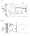
- FIG. 1 is a circuit diagram showing a configuration of an insulation resistance measuring circuit according to an exemplary embodiment of the present invention.
- an insulation resistance measuring analog circuit includes a battery 101, an insulation resistor 102, a source resistor unit 103 and 104, a voltage sensing unit 110, and an insulation resistance measuring unit 120.
- the source resistor unit includes a first source resistor 103 and a second source resistor 104, as shown in FIG. 1 .
- the voltage sensing unit 110 includes a first circuit unit 111 and a second circuit unit 112.
- the insulation resistance measuring unit 120 includes a first subtracter 121, an adder 122, an absolute value circuit 123, a divider 124, a voltage source 125, a second subtracter 126, an amplifier 127, a reference voltage outputter 128, and a third subtracter 129.
- the source resistor unit includes the first source resistor 103 connected between a positive terminal of the battery 101 and the second source resistor 104 and the second source resistor 104 connected between a negative terminal of the battery 101 and the first source resistor 103. That is, as shown in FIG. 1 , the first source resistor R s 103 is may be connected to the positive terminal of the battery 101 through a resistor R, and the second source resistor R s 104 may be connected to the negative terminal of the battery 101 through a resistor R. The first source resistor R s 103 and the second source resistor R s 104 may be connected to each other through a ground.
- the voltage sensing unit 110 senses a voltage of the first source resistor 103 as a first voltage and senses a voltage of the second source resistor 104 as a second voltage. As described above, the voltage sensing unit 110 includes the first circuit unit 111 and the second circuit unit 112.
- the first circuit unit 111 includes a first operational amplifier (OP Amp). Each of a non-inverting terminal and an inverting terminal of the first OP Amp may be connected to both ends of the first source resistor 103.
- the first circuit unit 111 may sense a first source voltage applied to the first source resistor 103 through the first OP Amp as the first voltage and output the sensed first source voltage through an output terminal thereof.
- the second circuit unit 112 includes a second OP Amp. Each of a non-inverting terminal and an inverting terminal of the second OP Amp may be connected to both ends of the second source resistor 104.
- the second circuit unit 112 may sense a second source voltage applied to the second source resistor 104 through the second OP Amp as a second source voltage and output the sensed second source voltage through an output terminal thereof.
- the insulation resistance measuring unit 120 measures an insulation resistance 102 of the battery 101 through a value obtained by dividing a difference between the first and second voltages by a sum between the first and second voltages. Further, the insulation resistance measuring unit 120 includes the first subtracter 121, the adder 122, the absolute value circuit 123, the divider 124, the voltage source 125, the second subtracter 126, the amplifier 127, the reference voltage outputter 128, and the third subtracter 129.
- the first subtracter 121 may be connected to each of an output terminal of the first OP Amp and an output terminal of the second OP Amp.
- the first subtracter 121 receives the first voltage output from the output terminal of the first OP Amp and the second voltage output from the output terminal of the second OP Amp and outputs a third voltage obtained by subtracting the second voltage from the first voltage.
- the adder 122 may be connected to each of the output terminal of the first OP Amp and the output terminal of the second OP Amp.
- the adder 122 receives the first voltage output from the output terminal of the first OP Amp and the second voltage output from the output terminal of the second OP Amp and outputs a fourth voltage obtained by adding the second voltage to the first voltage.
- the absolute value circuit 123 may be connected to an output terminal of the adder 122 and receives the fourth voltage from the output terminal of the adder 122 and outputs an absolute value of the fourth voltage as a fifth voltage.
- the divider 124 may be connected to each of an output terminal of the first subtracter 121 and an output terminal of the second OP Amp.
- the divider 124 receives the third voltage output from the first subtracter 121 and the fifth voltage output from the absolute value circuit 123 and outputs a sixth voltage obtained by dividing the third voltage by the fifth voltage.
- the second subtracter 126 may be connected to each of an output terminal of the divider 124 and an output terminal of the voltage source 125.
- the second subtract 126 receives the sixth voltage output from the divider 124 and a seventh voltage output from the voltage source 125 and outputs an eighth voltage obtained by subtracting the seventh voltage from the sixth voltage.
- the insulation resistance measuring unit 120 may further include any one or more of the amplifier 127, the reference voltage outputter 128, and the third subtracter 129 in order to more precisely measure the insulation resistance 102.
- the amplifier 127 may be connected to an output terminal of the second subtracter 124 and receives the eighth voltage from the output terminal of the second subtracter 124 and outputs a ninth voltage obtained by amplifying the eighth voltage through multiplication between the eighth voltage and a voltage gain G of the amplifier 127.
- the third subtracter 129 may be connected to each of an output terminal of the amplifier 127 and an output terminal of the reference voltage outputter 128.
- the third subtract 129 receives the ninth voltage output from the amplifier 127 and a tenth voltage output from the reference voltage outputter 128 and outputs an eleventh voltage obtained by subtracting the tenth voltage from the ninth voltage.
- the insulation resistance measuring unit 120 measures the insulation resistance 102 of the battery 101 through a value obtained by dividing the difference between the first and second voltages by the sum between the first and second voltages. A detailed description thereof will be provided through the following exemplary embodiment.
- a voltage of the battery 101 is V
- the insulation resistance 102 of the battery 101 is R iso
- each of resistance values of the first and second source resistors 103 and 104 is R s
- the first voltage output from the first circuit unit 111 is V 1
- the second voltage output from the second circuit unit 112 is V 2
- the third voltage output from the first subtracter 121 is V 3
- the fourth voltage output from the adder 122 is V 4 .
- V ⁇ 1 Rs R + Rs ⁇ Riso 2 ⁇ Riso + Rs + R ⁇ V
- V ⁇ 2 - Rs R + Rs ⁇ Riso + Rs + R 2 ⁇ Riso + Rs + R ⁇ V
- Equation 4 The fourth voltage measured at the time of the insulation breakdown of the cathode of the battery 101 is given by Equation 4.
- V ⁇ 4 - Rs R + Rs ⁇ R + Rs 2 ⁇ Riso + Rs + R ⁇ V
- Equation 5 The first voltage measured at the time of insulation breakdown of an anode of the battery 101 is given by Equation 5.
- V ⁇ 1 Rs R + Rs ⁇ Riso + Rs + R 2 ⁇ Riso + Rs + R ⁇ V
- V ⁇ 2 - Rs R + Rs ⁇ Riso 2 ⁇ Riso + Rs + R ⁇ V
- Equation 7 The third voltage measured at the time of the insulation breakdown of the anode of the battery 101 is given by Equation 7.
- V ⁇ 3 Rs R + Rs ⁇ V
- Equation 8 The fourth voltage measured at the time of the insulation breakdown of the anode of the battery 101 is given by Equation 8.
- V ⁇ 4 Rs R + Rs ⁇ R + Rs 2 ⁇ Riso + Rs + R ⁇ V
- Equation 9 The eighth voltage measured at the time of the insulation breakdown of the cathode or the insulation breakdown of the anode of the battery 101 is given by Equation 9.
- V ⁇ 8 2 ⁇ Riso Rs + R
- the insulation resistance of the battery 101 may be measured through the eighth voltage of Equation 9. That is, since R s and R are fixed resistance values in the eighth voltage, the eighth voltage changes in proportion to a value of R iso , which is the insulation resistance 102 of the battery 101. Therefore, the insulation resistance 102 of the battery 101 may be measured by measuring the eighth voltage.
- the ninth voltage may be calculated by multiplying the eighth voltage by the voltage gain G of the amplifier 127.
- the eleventh voltage may be calculated by receiving the reference voltage from a user and subtracting the reference voltage from the ninth voltage.
- the eleventh voltage is given by Equation 11.
- V ⁇ 11 2 Rs + R ⁇ G Riso - V ⁇ 10
- the insulation resistance 102 of the battery 101 may be measured through the eleventh voltage of Equation 11. That is, since R s ,R,G, and V 10 are fixed resistance values in Equation 11, the eleventh voltage value may change in proportion to R iso , which is a value of the insulation resistance 102. Therefore, the insulation resistance 102 of the battery 101 may be measured by measuring the eleventh voltage.
- the insulation resistance measuring circuit according to the exemplary embodiment of the present invention described with reference to FIG. 1 may be implemented as one-chip. That is, the source resistor unit 103 and 104, the voltage sensing unit 110, and the insulation resistance measuring unit 120 may be implemented as various kinds of one-chips widely used in the art, that is, a single semiconductor chip.
- the insulation resistance measuring circuit according to the exemplary embodiment of the present invention may be implemented as an analog circuit in which the insulation resistance measuring unit 120 includes a subtracter, a divider, or the like.
- the insulation resistance measuring unit 120 is not implemented as the analog circuit but may be implemented as a digital circuit including a microcontroller. This will be described with reference to FIG. 2 .
- FIG. 2 is a circuit diagram showing a configuration of an insulation resistance measuring circuit according to another exemplary embodiment of the present invention.
- the insulation resistance measuring circuit according to another exemplary embodiment of the present invention may be implemented as a digital circuit including a microcontroller.
- the insulation resistance measuring digital circuit includes a battery 101, an insulation resistor 102, a source resistor unit 103 and 104, a first OP Amp 111, a second OP Amp 112, an analog to digital converter 130, and a microcontroller 140.
- the source resistor unit includes a first source resistor 103 and a second source resistor 104, as shown in FIG. 2 .
- the source resistor unit includes the first source resistor 103 connected between a positive terminal of the battery 101 and the second source resistor 104 and the second source resistor 104 connected between a negative terminal of the battery 101 and the first source resistor 103. That is, as shown in FIG. 1 , the first source resistor R s 103 is may be connected to the positive terminal of the battery 101 through a resistor R, and the second source resistor R s 104 may be connected to the negative terminal of the battery 101 through a resistor R. The first source resistor R s 103 and the second source resistor R s 104 may be connected to each other through a ground.
- Each of a non-inverting terminal and an inverting terminal of the first OP Amp 111 may be connected to both ends of the first source resistor 103.
- the first OP Amp 111 may sense a first source voltage applied to the first source resistor 103 as the first voltage and output the sensed first source voltage through an output terminal thereof.
- Each of a non-inverting terminal and an inverting terminal of the second OP Amp 112 may be connected to both ends of the second source resistor 104.
- the second OP Amp 112 may sense a second source voltage applied to the second source resistor 104 as the second voltage and output the sensed second source voltage through an output terminal thereof.
- the analog to digital converter 130 may receive the first voltage output from the first OP Amp 111 and the second voltage output from the second OP Amp 112, convert each of the first and second voltages into digital signals, and output first and second voltages signals.
- the microcontroller 140 may measure an insulation resistance 102 of the battery 101 through a value obtained by dividing a difference between the first voltage of the first voltage signal and the second voltage of the second voltage signal by a sum between the first voltage of the first voltage signal and the second voltage of the second voltage signal.
- the microcontroller 140 may receive each of the first voltage of the first voltage signal and the second voltage of the second voltage signal from the analog to digital converter 130, calculate a third voltage obtained by subtracting the second voltage of the second voltage signal from the first voltage of the first voltage signal, a fourth voltage obtained by adding the second voltage to the first voltage, a fifth voltage having an absolute value of the fourth voltage, a sixth voltage obtained by dividing the third voltage by the fifth voltage, a seventh voltage having a voltage of 1V, and an eighth voltage obtained by subtracting the seventh voltage from the sixth voltage, and measure the insulation resistance 102 of the battery 101 through the eighth voltage.
- the microcontroller 140 may calculate a ninth voltage obtained by amplifying the eighth voltage to a predetermined value, a tenth voltage having a predetermined reference voltage value, and an eleventh voltage obtained by subtracting the tenth voltage from the ninth voltage in order to more precisely measure the insulation resistance 102 and may measure the insulation resistance 102 of the battery 101 through the eleventh voltage. A detailed description thereof will be provided through the following exemplary embodiment.
- Equation 12 the first voltage measured at the time of insulation breakdown of a cathode of the battery 101 is given by Equation 12.
- V ⁇ 1 Rs R + Rs ⁇ Riso 2 ⁇ Riso + Rs + R ⁇ V
- V ⁇ 2 - Rs R + Rs ⁇ Riso + Rs + R 2 ⁇ Riso + Rs + R ⁇ V
- Equation 14 The third voltage measured at the time of the insulation breakdown of the cathode of the battery 101 is given by Equation 14.
- V ⁇ 3 Rs R + Rs ⁇ V
- V ⁇ 4 - Rs R + Rs ⁇ R + Rs 2 ⁇ Riso + Rs + R ⁇ V
- V ⁇ 1 Rs R + Rs ⁇ Riso + Rs + R 2 ⁇ Riso + Rs + R ⁇ V
- V ⁇ 2 - Rs R + Rs ⁇ Riso 2 ⁇ Riso + Rs + R ⁇ V
- Equation 18 The third voltage measured at the time of the insulation breakdown of the anode of the battery 101 is given by Equation 18.
- V ⁇ 3 Rs R + Rs ⁇ V
- V ⁇ 4 Rs R + Rs ⁇ R + Rs 2 ⁇ Riso + Rs + R ⁇ V
- Equation 20 The eighth voltage measured at the time of the insulation breakdown of the cathode or the insulation breakdown of the anode of the battery 101 is given by Equation 20.
- V ⁇ 8 2 ⁇ Riso Rs + R
- the microcontroller 140 may calculate the ninth voltage obtained by amplifying the eighth voltage to a predetermined value in order to more precisely measure the insulation resistance 102.
- the ninth voltage is given by Equation 21.
- V ⁇ 9 2 Rs + R ⁇ GRiso
- the microcontroller 140 may calculate the tenth voltage having a predetermined reference voltage value and the eleventh voltage obtained by subtracting the tenth voltage from the ninth voltage in order to more precisely measure the insulation resistance 102.
- the eleventh voltage is given by Equation 22.
- V ⁇ 11 2 Rs + R ⁇ G Riso - V ⁇ 10
- the insulation resistance R iso 102 of the battery 101 may be measured through the insulation resistance measuring unit 120 or the microcontroller 140. That is, the insulation breakdown of the cathode and the anode of the battery 101 capable of being implemented as the high voltage battery of the hybrid vehicle is judged as one signal to measure the insulation resistance 102, thereby making it possible to more simply and more precisely measure the insulation resistance 102.
- the insulation resistance measuring circuit according to another exemplary embodiment of the present invention described with reference to FIG. 2 may be implemented as one-chip. That is, the source resistor unit 103 and 104, the first OP Amp 111, the second OP Amp 112, the analog to digital converter 130, and the microcontroller 140 may be implemented as various kinds of one-chips widely used in the art, that is, a single semiconductor chip.
Landscapes
- Physics & Mathematics (AREA)
- General Physics & Mathematics (AREA)
- Measurement Of Resistance Or Impedance (AREA)
- Testing Of Short-Circuits, Discontinuities, Leakage, Or Incorrect Line Connections (AREA)
- Electric Propulsion And Braking For Vehicles (AREA)
- Measurement Of Current Or Voltage (AREA)
Applications Claiming Priority (2)
| Application Number | Priority Date | Filing Date | Title |
|---|---|---|---|
| KR1020090024341A KR101114317B1 (ko) | 2009-03-23 | 2009-03-23 | 배터리 전압의 영향을 받지 않는 절연저항 측정회로 |
| PCT/KR2010/001790 WO2010110589A2 (fr) | 2009-03-23 | 2010-03-23 | Circuit de mesure de la résistance d'isolement non influencé par la tension de batterie |
Publications (3)
| Publication Number | Publication Date |
|---|---|
| EP2413148A2 true EP2413148A2 (fr) | 2012-02-01 |
| EP2413148A4 EP2413148A4 (fr) | 2017-03-15 |
| EP2413148B1 EP2413148B1 (fr) | 2020-11-04 |
Family
ID=42781665
Family Applications (1)
| Application Number | Title | Priority Date | Filing Date |
|---|---|---|---|
| EP10756344.7A Active EP2413148B1 (fr) | 2009-03-23 | 2010-03-23 | Circuit de mesure de la résistance d'isolement non influencé par la tension de batterie |
Country Status (6)
| Country | Link |
|---|---|
| US (1) | US8779784B2 (fr) |
| EP (1) | EP2413148B1 (fr) |
| JP (1) | JP5464389B2 (fr) |
| KR (1) | KR101114317B1 (fr) |
| CN (1) | CN102362185B (fr) |
| WO (1) | WO2010110589A2 (fr) |
Cited By (3)
| Publication number | Priority date | Publication date | Assignee | Title |
|---|---|---|---|---|
| CN103439577A (zh) * | 2013-08-13 | 2013-12-11 | 重庆长安汽车股份有限公司 | 电动汽车动力电池的绝缘电阻检测系统及检测方法 |
| EP3451005A3 (fr) * | 2017-08-29 | 2019-03-27 | Contemporary Amperex Technology Co., Limited | Circuit de détection d'isolation, procédé de détection et système de gestion de batterie |
| WO2019179736A1 (fr) | 2018-03-23 | 2019-09-26 | IFP Energies Nouvelles | Procede de determination d'au moins deux resistances equivalentes d'isolement d'un systeme electrique |
Families Citing this family (39)
| Publication number | Priority date | Publication date | Assignee | Title |
|---|---|---|---|---|
| US9523730B2 (en) * | 2009-04-08 | 2016-12-20 | Analog Devices, Inc. | Architecture and method to determine leakage impedance and leakage voltage node |
| US8427167B2 (en) | 2009-04-08 | 2013-04-23 | Analog Devices, Inc. | Architecture and method to determine leakage impedance and leakage voltage node |
| US8421467B2 (en) * | 2009-11-19 | 2013-04-16 | Valence Technology, Inc. | Battery insulation resistance measurement methods, insulation resistance measurement methods, insulation resistance determination apparatuses, and articles of manufacture |
| DE102010026919A1 (de) * | 2010-07-13 | 2012-01-19 | Leopold Kostal Gmbh & Co. Kg | Verfahren zur Erfassung einer Schaltstellung einer Schalteinrichtung |
| KR101354583B1 (ko) * | 2010-09-17 | 2014-01-22 | 에스케이이노베이션 주식회사 | 누설전류를 발생시키지 않고 셀프 테스트 기능을 가진 절연저항 측정회로 |
| CN102621385B (zh) * | 2011-01-26 | 2014-07-30 | 致茂电子股份有限公司 | 电路稳定度补偿方法 |
| US9945910B2 (en) * | 2011-03-31 | 2018-04-17 | Renesas Electronics Corporation | Voltage monitoring module and voltage monitoring system which compares voltages to determine leakage |
| WO2013147494A1 (fr) * | 2012-03-26 | 2013-10-03 | 주식회사 엘지화학 | Dispositif et procédé de mesure de la résistance d'isolement d'une batterie |
| PL2796887T3 (pl) * | 2012-03-27 | 2020-05-18 | Lg Chem, Ltd. | Aparat do pomiaru rezystancji izolacji, mający funkcję autodiagnozowania usterek, oraz sposób autodiagnozowania usterek przy jego użyciu |
| CN102944744A (zh) * | 2012-11-06 | 2013-02-27 | 昆山北极光电子科技有限公司 | 一种低漂移在线阻抗测量电路 |
| CN103837806A (zh) * | 2012-11-21 | 2014-06-04 | 赵元雷 | 电动汽车高压动力电源系统绝缘程度监测报警装置 |
| CN103869166B (zh) * | 2012-12-18 | 2017-02-08 | 中信国安盟固利动力科技有限公司 | 一种电池系统绝缘电阻的测量及故障点定位装置 |
| TWI497860B (zh) * | 2013-08-06 | 2015-08-21 | Elifeconnection Co Ltd | 多埠電源監控系統 |
| US9194918B2 (en) * | 2013-12-12 | 2015-11-24 | Ford Global Technologies, Llc | Leakage detection circuit with integral circuit robustness check |
| JP6212403B2 (ja) * | 2014-02-10 | 2017-10-11 | 本田技研工業株式会社 | 絶縁性検出装置 |
| US9411004B2 (en) * | 2014-05-28 | 2016-08-09 | Ford Global Technologies, Llc | Continuous leakage detection circuit with integrated robustness check and balanced fault detection |
| CN104569598A (zh) * | 2015-01-08 | 2015-04-29 | 国家电网公司 | 一种高压电池储能系统绝缘电阻的无损检测电路及方法 |
| DE102015101074B4 (de) * | 2015-01-26 | 2021-10-07 | Lisa Dräxlmaier GmbH | Verfahren und Vorrichtung zur Bestimmung einer Isolationsgröße sowie Kraftfahrzeug mit dieser Vorrichtung |
| KR101746141B1 (ko) * | 2015-03-10 | 2017-06-13 | 주식회사 엘지화학 | 절연저항측정 장치 및 방법 |
| KR102348303B1 (ko) | 2015-06-19 | 2022-01-06 | 삼성전자주식회사 | 배터리 모듈의 누설 전류 감지 장치 및 방법 |
| KR101936220B1 (ko) * | 2015-11-16 | 2019-01-08 | 주식회사 엘지화학 | 절연 저항 측정 시스템 및 장치 |
| DE102016208960B3 (de) | 2016-05-24 | 2017-11-09 | Continental Automotive Gmbh | Überwachungsvorrichtung und Verfahren zum Überwachen einer gegenüber einem Referenzpotential galvanisch entkoppelten Wechselspannungsquelle |
| KR101991910B1 (ko) * | 2016-11-16 | 2019-06-21 | 주식회사 엘지화학 | 배터리의 절연 저항 산출 장치 및 방법 |
| KR102032020B1 (ko) * | 2016-11-25 | 2019-11-08 | 주식회사 엘지화학 | Bms 내 절연소자 진단 시스템 |
| KR101960293B1 (ko) * | 2017-02-14 | 2019-03-20 | 에스케이이노베이션 주식회사 | 절연저항 측정방법 및 측정장치 |
| DE102017218732A1 (de) | 2017-10-19 | 2019-04-25 | Volkswagen Aktiengesellschaft | Spannungsmessverfahren, Betriebsverfahren und Steuereinrichtung für ein Bordnetz sowie Bordnetz und Fahrzeug |
| TWI661204B (zh) * | 2018-07-16 | 2019-06-01 | 昆山富士錦電子有限公司 | 絕緣電阻量測裝置 |
| KR102256096B1 (ko) * | 2018-08-27 | 2021-05-27 | 주식회사 엘지에너지솔루션 | 배터리팩과 접지 간의 절연 상태를 진단하기 위한 장치 및 방법과, 상기 장치를 포함하는 배터리팩 |
| CN109633462B (zh) * | 2018-12-29 | 2021-04-20 | 蜂巢能源科技有限公司 | 电池管理系统中电池电压状态检测方法及检测系统和电池管理系统 |
| CN109765495B (zh) * | 2019-01-15 | 2020-11-10 | 宁德时代新能源科技股份有限公司 | 绝缘检测电路及检测方法、电池管理系统 |
| KR102672495B1 (ko) * | 2019-03-15 | 2024-06-07 | 에스케이온 주식회사 | 절연저항 측정 장치 |
| CN111929502A (zh) * | 2019-05-13 | 2020-11-13 | 上海海拉电子有限公司 | 一种绝缘检测电路及方法 |
| CN111929501B (zh) * | 2019-05-13 | 2023-04-25 | 上海海拉电子有限公司 | 一种绝缘阻值变化检测电路、一种绝缘检测系统及方法 |
| KR102181229B1 (ko) | 2019-06-28 | 2020-11-24 | (주)에이치엠지 | 절연 저항 측정 장치 및 절연 저항 측정 방법 |
| KR102804359B1 (ko) * | 2020-04-13 | 2025-05-09 | 에스케이온 주식회사 | 절연 저항 측정 장치 |
| CN112198368B (zh) * | 2020-09-22 | 2022-09-09 | 合肥国轩高科动力能源有限公司 | 一种电动汽车绝缘电阻检测电路及方法 |
| CN113791277A (zh) * | 2021-09-16 | 2021-12-14 | 惠州市乐亿通科技有限公司 | 绝缘电阻检测装置及叉车 |
| CN114264879B (zh) * | 2021-12-13 | 2024-10-01 | 航天新长征大道科技有限公司 | 一种绝缘电阻和导通电阻的测量装置和系统 |
| US12578387B2 (en) * | 2024-01-04 | 2026-03-17 | Hitachi Astemo, Ltd. | Systems and methods for fault detection, diagnosis, and recovery in an electromechanical actuator |
Family Cites Families (33)
| Publication number | Priority date | Publication date | Assignee | Title |
|---|---|---|---|---|
| JPS59220660A (ja) * | 1983-05-30 | 1984-12-12 | Shonan Denshi Kogyo:Kk | 演算形絶縁計 |
| US4816768A (en) * | 1988-03-18 | 1989-03-28 | Champlin Keith S | Electronic battery testing device |
| US5742148A (en) * | 1992-11-24 | 1998-04-21 | Seiko Instruments Inc. | Charge/discharge control circuit and chargeable electric power source apparatus |
| JP3041150B2 (ja) * | 1993-02-15 | 2000-05-15 | 松下電器産業株式会社 | 漏電検出装置 |
| JP3434760B2 (ja) | 1993-10-19 | 2003-08-11 | セイコーインスツルメンツ株式会社 | 充放電制御回路と充電式電源装置 |
| DE19618897B4 (de) * | 1996-05-10 | 2006-04-20 | Varta Automotive Systems Gmbh | Schaltungsanordnung zur Bestimmung des Isolationswiderstandes einer Akkumulatorenbatterie |
| JP4003278B2 (ja) * | 1998-02-20 | 2007-11-07 | ソニー株式会社 | 電池の電圧検出回路と電池の電圧検出方法 |
| US6002238A (en) * | 1998-09-11 | 1999-12-14 | Champlin; Keith S. | Method and apparatus for measuring complex impedance of cells and batteries |
| US6262563B1 (en) * | 1998-09-11 | 2001-07-17 | Keith S. Champlin | Method and apparatus for measuring complex admittance of cells and batteries |
| MY121524A (en) * | 1999-09-22 | 2006-01-28 | Murata Manufacturing Co | Insulation resistance measuring apparatus for capacitive electronic parts |
| JP3548887B2 (ja) * | 1999-12-20 | 2004-07-28 | 株式会社村田製作所 | 絶縁抵抗測定方法および装置 |
| JP3600211B2 (ja) * | 2000-02-22 | 2004-12-15 | 三洋電機株式会社 | 電源装置の漏電検出回路 |
| JP3594562B2 (ja) * | 2001-03-30 | 2004-12-02 | 三洋電機株式会社 | 電源装置の漏電検出回路 |
| JP2003066090A (ja) * | 2001-08-29 | 2003-03-05 | Omron Corp | 漏電検出装置 |
| US6466026B1 (en) * | 2001-10-12 | 2002-10-15 | Keith S. Champlin | Programmable current exciter for measuring AC immittance of cells and batteries |
| KR20050047079A (ko) * | 2002-07-19 | 2005-05-19 | 셀레리티 그룹 아이엔씨 | 공용 기준 레그를 갖는 가변 저항기 센서 |
| JP3957598B2 (ja) | 2002-09-10 | 2007-08-15 | 松下電器産業株式会社 | 絶縁抵抗検出方法および装置 |
| DE10300539B4 (de) | 2003-01-09 | 2007-05-24 | Daimlerchrysler Ag | Schaltung und Verfahren zur Erfassung von Isolationsfehlern |
| JP2005114496A (ja) * | 2003-10-07 | 2005-04-28 | Yazaki Corp | 状態検出方法及び絶縁抵抗低下検出器 |
| US7317316B2 (en) * | 2004-07-02 | 2008-01-08 | Nucellsys Gmbh | Apparatus and method for measuring the insulation resistance of a fuel cell system |
| JP2006220520A (ja) * | 2005-02-10 | 2006-08-24 | Honda Motor Co Ltd | 非接地直流電源の絶縁抵抗測定装置及びその方法 |
| JP4834393B2 (ja) * | 2005-12-09 | 2011-12-14 | 矢崎総業株式会社 | 状態検出方法及び絶縁抵抗低下検出器 |
| US20070210805A1 (en) * | 2006-03-08 | 2007-09-13 | Yazaki Corporation | Insulation detecting method and insulation detecting device |
| JP4785627B2 (ja) * | 2006-06-08 | 2011-10-05 | 三洋電機株式会社 | 電動車両用漏電検出回路および電動車両用漏電検出方法 |
| JP4241787B2 (ja) | 2006-09-06 | 2009-03-18 | 日立ビークルエナジー株式会社 | 組電池総電圧検出およびリーク検出装置 |
| JP2009085830A (ja) * | 2007-10-01 | 2009-04-23 | Toyota Industries Corp | 産業車両における絶縁抵抗低下検出装置 |
| CN101281230A (zh) * | 2008-04-25 | 2008-10-08 | 奇瑞汽车股份有限公司 | 一种用于混合动力汽车高压系统的绝缘故障监测装置及方法 |
| JP4759018B2 (ja) * | 2008-05-26 | 2011-08-31 | 矢崎総業株式会社 | 絶縁計測装置 |
| JP4659067B2 (ja) * | 2008-05-26 | 2011-03-30 | 矢崎総業株式会社 | 絶縁計測方法及び絶縁計測装置 |
| GB0816452D0 (en) * | 2008-09-09 | 2008-10-15 | Ricardo Uk Ltd | Isolation detection |
| JP5613408B2 (ja) * | 2009-10-13 | 2014-10-22 | 矢崎総業株式会社 | 絶縁計測装置 |
| US8421467B2 (en) * | 2009-11-19 | 2013-04-16 | Valence Technology, Inc. | Battery insulation resistance measurement methods, insulation resistance measurement methods, insulation resistance determination apparatuses, and articles of manufacture |
| KR101908637B1 (ko) * | 2012-01-05 | 2018-10-17 | 에스케이이노베이션 주식회사 | 절연 저항 측정 회로 |
-
2009
- 2009-03-23 KR KR1020090024341A patent/KR101114317B1/ko active Active
-
2010
- 2010-03-23 EP EP10756344.7A patent/EP2413148B1/fr active Active
- 2010-03-23 WO PCT/KR2010/001790 patent/WO2010110589A2/fr not_active Ceased
- 2010-03-23 JP JP2012501935A patent/JP5464389B2/ja active Active
- 2010-03-23 US US13/257,831 patent/US8779784B2/en active Active
- 2010-03-23 CN CN201080013324.9A patent/CN102362185B/zh active Active
Non-Patent Citations (1)
| Title |
|---|
| See references of WO2010110589A2 * |
Cited By (4)
| Publication number | Priority date | Publication date | Assignee | Title |
|---|---|---|---|---|
| CN103439577A (zh) * | 2013-08-13 | 2013-12-11 | 重庆长安汽车股份有限公司 | 电动汽车动力电池的绝缘电阻检测系统及检测方法 |
| EP3451005A3 (fr) * | 2017-08-29 | 2019-03-27 | Contemporary Amperex Technology Co., Limited | Circuit de détection d'isolation, procédé de détection et système de gestion de batterie |
| US10775441B2 (en) | 2017-08-29 | 2020-09-15 | Contemporary Amperex Technology Co., Limited | Insulation detection circuit, detection method, and battery management system |
| WO2019179736A1 (fr) | 2018-03-23 | 2019-09-26 | IFP Energies Nouvelles | Procede de determination d'au moins deux resistances equivalentes d'isolement d'un systeme electrique |
Also Published As
| Publication number | Publication date |
|---|---|
| JP5464389B2 (ja) | 2014-04-09 |
| EP2413148A4 (fr) | 2017-03-15 |
| US8779784B2 (en) | 2014-07-15 |
| KR20100105962A (ko) | 2010-10-01 |
| JP2012521561A (ja) | 2012-09-13 |
| WO2010110589A2 (fr) | 2010-09-30 |
| EP2413148B1 (fr) | 2020-11-04 |
| CN102362185B (zh) | 2014-06-25 |
| CN102362185A (zh) | 2012-02-22 |
| US20120016613A1 (en) | 2012-01-19 |
| WO2010110589A3 (fr) | 2011-01-20 |
| KR101114317B1 (ko) | 2012-02-14 |
Similar Documents
| Publication | Publication Date | Title |
|---|---|---|
| EP2413148A2 (fr) | Circuit de mesure de la résistance d'isolement non influencé par la tension de batterie | |
| KR101114316B1 (ko) | 연산증폭기를 이용한 절연저항 측정회로 | |
| JP4241787B2 (ja) | 組電池総電圧検出およびリーク検出装置 | |
| US8004284B2 (en) | Leak detecting circuit | |
| US9255957B2 (en) | Earth fault detection circuit and power source device | |
| EP2105753B1 (fr) | Circuit de détection de tension totale de batterie assemblée | |
| EP1930737B1 (fr) | Appareil de détection de résistance d'isolement | |
| KR101585453B1 (ko) | 션트저항 타입 전류센서를 이용한 차량용 배터리의 전류 센싱 구조 | |
| JP2002296316A (ja) | 電源装置の漏電検出回路 | |
| KR101043445B1 (ko) | 배터리와 연결되는 저항을 이용한 절연저항 측정회로 | |
| EP3483616B1 (fr) | Circuit et procédé de détection | |
| EP1289094A1 (fr) | Détecteur de court-circuit | |
| EP2592427B1 (fr) | Circuit et procédé de mesure de tension électrique | |
| EP3958428B1 (fr) | Dispositif de commande, système de conversion d'énergie, procédé de conversion d'énergie et support de stockage | |
| EP2916448A1 (fr) | Dispositif de conversion de puissance et procédé pour diagnostiquer une défaillance du dispositif | |
| CN102472803A (zh) | 满充电容量值修正电路、电池组件及充电系统 | |
| EP2672279A1 (fr) | Barre d'alimentation et procédé de mesure d'alimentation | |
| JPWO2006080067A1 (ja) | 二次電池の充放電電気量推定方法および装置、二次電池の分極電圧推定方法および装置、並びに二次電池の残存容量推定方法および装置 | |
| EP3901640B1 (fr) | Appareil de mesure de la résistance d'isolation | |
| KR102158595B1 (ko) | 절연 감시 시스템 | |
| EP3164727B1 (fr) | Procédé, circuit, et chargeur de batterie | |
| CN117740180A (zh) | 温度采集装置 | |
| KR20070029883A (ko) | 감도 저항을 이용한 배터리 충전상태 표시장치 및 방법 |
Legal Events
| Date | Code | Title | Description |
|---|---|---|---|
| PUAI | Public reference made under article 153(3) epc to a published international application that has entered the european phase |
Free format text: ORIGINAL CODE: 0009012 |
|
| 17P | Request for examination filed |
Effective date: 20110922 |
|
| AK | Designated contracting states |
Kind code of ref document: A2 Designated state(s): AT BE BG CH CY CZ DE DK EE ES FI FR GB GR HR HU IE IS IT LI LT LU LV MC MK MT NL NO PL PT RO SE SI SK SM TR |
|
| DAX | Request for extension of the european patent (deleted) | ||
| A4 | Supplementary search report drawn up and despatched |
Effective date: 20170215 |
|
| RIC1 | Information provided on ipc code assigned before grant |
Ipc: G01R 31/12 20060101ALI20170209BHEP Ipc: G01R 27/02 20060101ALI20170209BHEP Ipc: G01R 27/08 20060101AFI20170209BHEP Ipc: G01R 27/16 20060101ALI20170209BHEP |
|
| GRAP | Despatch of communication of intention to grant a patent |
Free format text: ORIGINAL CODE: EPIDOSNIGR1 |
|
| STAA | Information on the status of an ep patent application or granted ep patent |
Free format text: STATUS: GRANT OF PATENT IS INTENDED |
|
| RIC1 | Information provided on ipc code assigned before grant |
Ipc: G01R 27/02 20060101ALI20200423BHEP Ipc: G01R 27/08 20060101AFI20200423BHEP Ipc: G01R 31/12 20200101ALI20200423BHEP Ipc: G01R 27/16 20060101ALI20200423BHEP |
|
| INTG | Intention to grant announced |
Effective date: 20200527 |
|
| GRAS | Grant fee paid |
Free format text: ORIGINAL CODE: EPIDOSNIGR3 |
|
| GRAA | (expected) grant |
Free format text: ORIGINAL CODE: 0009210 |
|
| STAA | Information on the status of an ep patent application or granted ep patent |
Free format text: STATUS: THE PATENT HAS BEEN GRANTED |
|
| AK | Designated contracting states |
Kind code of ref document: B1 Designated state(s): AT BE BG CH CY CZ DE DK EE ES FI FR GB GR HR HU IE IS IT LI LT LU LV MC MK MT NL NO PL PT RO SE SI SK SM TR |
|
| REG | Reference to a national code |
Ref country code: GB Ref legal event code: FG4D |
|
| REG | Reference to a national code |
Ref country code: CH Ref legal event code: EP |
|
| REG | Reference to a national code |
Ref country code: AT Ref legal event code: REF Ref document number: 1331504 Country of ref document: AT Kind code of ref document: T Effective date: 20201115 |
|
| REG | Reference to a national code |
Ref country code: DE Ref legal event code: R096 Ref document number: 602010065832 Country of ref document: DE |
|
| REG | Reference to a national code |
Ref country code: IE Ref legal event code: FG4D |
|
| REG | Reference to a national code |
Ref country code: NL Ref legal event code: MP Effective date: 20201104 |
|
| REG | Reference to a national code |
Ref country code: AT Ref legal event code: MK05 Ref document number: 1331504 Country of ref document: AT Kind code of ref document: T Effective date: 20201104 |
|
| PG25 | Lapsed in a contracting state [announced via postgrant information from national office to epo] |
Ref country code: PT Free format text: LAPSE BECAUSE OF FAILURE TO SUBMIT A TRANSLATION OF THE DESCRIPTION OR TO PAY THE FEE WITHIN THE PRESCRIBED TIME-LIMIT Effective date: 20210304 Ref country code: NO Free format text: LAPSE BECAUSE OF FAILURE TO SUBMIT A TRANSLATION OF THE DESCRIPTION OR TO PAY THE FEE WITHIN THE PRESCRIBED TIME-LIMIT Effective date: 20210204 Ref country code: FI Free format text: LAPSE BECAUSE OF FAILURE TO SUBMIT A TRANSLATION OF THE DESCRIPTION OR TO PAY THE FEE WITHIN THE PRESCRIBED TIME-LIMIT Effective date: 20201104 Ref country code: GR Free format text: LAPSE BECAUSE OF FAILURE TO SUBMIT A TRANSLATION OF THE DESCRIPTION OR TO PAY THE FEE WITHIN THE PRESCRIBED TIME-LIMIT Effective date: 20210205 |
|
| PG25 | Lapsed in a contracting state [announced via postgrant information from national office to epo] |
Ref country code: SE Free format text: LAPSE BECAUSE OF FAILURE TO SUBMIT A TRANSLATION OF THE DESCRIPTION OR TO PAY THE FEE WITHIN THE PRESCRIBED TIME-LIMIT Effective date: 20201104 Ref country code: PL Free format text: LAPSE BECAUSE OF FAILURE TO SUBMIT A TRANSLATION OF THE DESCRIPTION OR TO PAY THE FEE WITHIN THE PRESCRIBED TIME-LIMIT Effective date: 20201104 Ref country code: LV Free format text: LAPSE BECAUSE OF FAILURE TO SUBMIT A TRANSLATION OF THE DESCRIPTION OR TO PAY THE FEE WITHIN THE PRESCRIBED TIME-LIMIT Effective date: 20201104 Ref country code: AT Free format text: LAPSE BECAUSE OF FAILURE TO SUBMIT A TRANSLATION OF THE DESCRIPTION OR TO PAY THE FEE WITHIN THE PRESCRIBED TIME-LIMIT Effective date: 20201104 Ref country code: BG Free format text: LAPSE BECAUSE OF FAILURE TO SUBMIT A TRANSLATION OF THE DESCRIPTION OR TO PAY THE FEE WITHIN THE PRESCRIBED TIME-LIMIT Effective date: 20210204 Ref country code: IS Free format text: LAPSE BECAUSE OF FAILURE TO SUBMIT A TRANSLATION OF THE DESCRIPTION OR TO PAY THE FEE WITHIN THE PRESCRIBED TIME-LIMIT Effective date: 20210304 Ref country code: ES Free format text: LAPSE BECAUSE OF FAILURE TO SUBMIT A TRANSLATION OF THE DESCRIPTION OR TO PAY THE FEE WITHIN THE PRESCRIBED TIME-LIMIT Effective date: 20201104 |
|
| REG | Reference to a national code |
Ref country code: LT Ref legal event code: MG9D |
|
| PG25 | Lapsed in a contracting state [announced via postgrant information from national office to epo] |
Ref country code: HR Free format text: LAPSE BECAUSE OF FAILURE TO SUBMIT A TRANSLATION OF THE DESCRIPTION OR TO PAY THE FEE WITHIN THE PRESCRIBED TIME-LIMIT Effective date: 20201104 |
|
| PG25 | Lapsed in a contracting state [announced via postgrant information from national office to epo] |
Ref country code: LT Free format text: LAPSE BECAUSE OF FAILURE TO SUBMIT A TRANSLATION OF THE DESCRIPTION OR TO PAY THE FEE WITHIN THE PRESCRIBED TIME-LIMIT Effective date: 20201104 Ref country code: RO Free format text: LAPSE BECAUSE OF FAILURE TO SUBMIT A TRANSLATION OF THE DESCRIPTION OR TO PAY THE FEE WITHIN THE PRESCRIBED TIME-LIMIT Effective date: 20201104 Ref country code: SK Free format text: LAPSE BECAUSE OF FAILURE TO SUBMIT A TRANSLATION OF THE DESCRIPTION OR TO PAY THE FEE WITHIN THE PRESCRIBED TIME-LIMIT Effective date: 20201104 Ref country code: SM Free format text: LAPSE BECAUSE OF FAILURE TO SUBMIT A TRANSLATION OF THE DESCRIPTION OR TO PAY THE FEE WITHIN THE PRESCRIBED TIME-LIMIT Effective date: 20201104 Ref country code: EE Free format text: LAPSE BECAUSE OF FAILURE TO SUBMIT A TRANSLATION OF THE DESCRIPTION OR TO PAY THE FEE WITHIN THE PRESCRIBED TIME-LIMIT Effective date: 20201104 Ref country code: CZ Free format text: LAPSE BECAUSE OF FAILURE TO SUBMIT A TRANSLATION OF THE DESCRIPTION OR TO PAY THE FEE WITHIN THE PRESCRIBED TIME-LIMIT Effective date: 20201104 |
|
| REG | Reference to a national code |
Ref country code: DE Ref legal event code: R097 Ref document number: 602010065832 Country of ref document: DE |
|
| PG25 | Lapsed in a contracting state [announced via postgrant information from national office to epo] |
Ref country code: DK Free format text: LAPSE BECAUSE OF FAILURE TO SUBMIT A TRANSLATION OF THE DESCRIPTION OR TO PAY THE FEE WITHIN THE PRESCRIBED TIME-LIMIT Effective date: 20201104 |
|
| PLBE | No opposition filed within time limit |
Free format text: ORIGINAL CODE: 0009261 |
|
| STAA | Information on the status of an ep patent application or granted ep patent |
Free format text: STATUS: NO OPPOSITION FILED WITHIN TIME LIMIT |
|
| 26N | No opposition filed |
Effective date: 20210805 |
|
| PG25 | Lapsed in a contracting state [announced via postgrant information from national office to epo] |
Ref country code: NL Free format text: LAPSE BECAUSE OF FAILURE TO SUBMIT A TRANSLATION OF THE DESCRIPTION OR TO PAY THE FEE WITHIN THE PRESCRIBED TIME-LIMIT Effective date: 20201104 Ref country code: MC Free format text: LAPSE BECAUSE OF FAILURE TO SUBMIT A TRANSLATION OF THE DESCRIPTION OR TO PAY THE FEE WITHIN THE PRESCRIBED TIME-LIMIT Effective date: 20201104 Ref country code: IT Free format text: LAPSE BECAUSE OF FAILURE TO SUBMIT A TRANSLATION OF THE DESCRIPTION OR TO PAY THE FEE WITHIN THE PRESCRIBED TIME-LIMIT Effective date: 20201104 |
|
| REG | Reference to a national code |
Ref country code: CH Ref legal event code: PL |
|
| GBPC | Gb: european patent ceased through non-payment of renewal fee |
Effective date: 20210323 |
|
| PG25 | Lapsed in a contracting state [announced via postgrant information from national office to epo] |
Ref country code: SI Free format text: LAPSE BECAUSE OF FAILURE TO SUBMIT A TRANSLATION OF THE DESCRIPTION OR TO PAY THE FEE WITHIN THE PRESCRIBED TIME-LIMIT Effective date: 20201104 |
|
| REG | Reference to a national code |
Ref country code: BE Ref legal event code: MM Effective date: 20210331 |
|
| PG25 | Lapsed in a contracting state [announced via postgrant information from national office to epo] |
Ref country code: CH Free format text: LAPSE BECAUSE OF NON-PAYMENT OF DUE FEES Effective date: 20210331 Ref country code: LU Free format text: LAPSE BECAUSE OF NON-PAYMENT OF DUE FEES Effective date: 20210323 Ref country code: LI Free format text: LAPSE BECAUSE OF NON-PAYMENT OF DUE FEES Effective date: 20210331 Ref country code: IE Free format text: LAPSE BECAUSE OF NON-PAYMENT OF DUE FEES Effective date: 20210323 Ref country code: FR Free format text: LAPSE BECAUSE OF NON-PAYMENT OF DUE FEES Effective date: 20210331 Ref country code: GB Free format text: LAPSE BECAUSE OF NON-PAYMENT OF DUE FEES Effective date: 20210323 |
|
| PG25 | Lapsed in a contracting state [announced via postgrant information from national office to epo] |
Ref country code: IS Free format text: LAPSE BECAUSE OF FAILURE TO SUBMIT A TRANSLATION OF THE DESCRIPTION OR TO PAY THE FEE WITHIN THE PRESCRIBED TIME-LIMIT Effective date: 20210304 |
|
| PG25 | Lapsed in a contracting state [announced via postgrant information from national office to epo] |
Ref country code: BE Free format text: LAPSE BECAUSE OF NON-PAYMENT OF DUE FEES Effective date: 20210331 |
|
| REG | Reference to a national code |
Ref country code: DE Ref legal event code: R081 Ref document number: 602010065832 Country of ref document: DE Owner name: SK ON CO., LTD., KR Free format text: FORMER OWNER: SK INNOVATION CO., LTD., SEOUL, KR |
|
| PG25 | Lapsed in a contracting state [announced via postgrant information from national office to epo] |
Ref country code: HU Free format text: LAPSE BECAUSE OF FAILURE TO SUBMIT A TRANSLATION OF THE DESCRIPTION OR TO PAY THE FEE WITHIN THE PRESCRIBED TIME-LIMIT; INVALID AB INITIO Effective date: 20100323 Ref country code: CY Free format text: LAPSE BECAUSE OF FAILURE TO SUBMIT A TRANSLATION OF THE DESCRIPTION OR TO PAY THE FEE WITHIN THE PRESCRIBED TIME-LIMIT Effective date: 20201104 |
|
| P01 | Opt-out of the competence of the unified patent court (upc) registered |
Effective date: 20230602 |
|
| PG25 | Lapsed in a contracting state [announced via postgrant information from national office to epo] |
Ref country code: MK Free format text: LAPSE BECAUSE OF FAILURE TO SUBMIT A TRANSLATION OF THE DESCRIPTION OR TO PAY THE FEE WITHIN THE PRESCRIBED TIME-LIMIT Effective date: 20201104 |
|
| PG25 | Lapsed in a contracting state [announced via postgrant information from national office to epo] |
Ref country code: TR Free format text: LAPSE BECAUSE OF FAILURE TO SUBMIT A TRANSLATION OF THE DESCRIPTION OR TO PAY THE FEE WITHIN THE PRESCRIBED TIME-LIMIT Effective date: 20201104 |
|
| PG25 | Lapsed in a contracting state [announced via postgrant information from national office to epo] |
Ref country code: MT Free format text: LAPSE BECAUSE OF FAILURE TO SUBMIT A TRANSLATION OF THE DESCRIPTION OR TO PAY THE FEE WITHIN THE PRESCRIBED TIME-LIMIT Effective date: 20201104 |
|
| PGFP | Annual fee paid to national office [announced via postgrant information from national office to epo] |
Ref country code: DE Payment date: 20251222 Year of fee payment: 17 |