EP2418007B1 - Spielzeug - Google Patents
Spielzeug Download PDFInfo
- Publication number
- EP2418007B1 EP2418007B1 EP11174870.3A EP11174870A EP2418007B1 EP 2418007 B1 EP2418007 B1 EP 2418007B1 EP 11174870 A EP11174870 A EP 11174870A EP 2418007 B1 EP2418007 B1 EP 2418007B1
- Authority
- EP
- European Patent Office
- Prior art keywords
- target
- game toy
- tray
- game
- arm
- Prior art date
- Legal status (The legal status is an assumption and is not a legal conclusion. Google has not performed a legal analysis and makes no representation as to the accuracy of the status listed.)
- Not-in-force
Links
Images



Classifications
-
- A—HUMAN NECESSITIES
- A63—SPORTS; GAMES; AMUSEMENTS
- A63F—CARD, BOARD, OR ROULETTE GAMES; INDOOR GAMES USING SMALL MOVING PLAYING BODIES; VIDEO GAMES; GAMES NOT OTHERWISE PROVIDED FOR
- A63F7/00—Indoor games using small moving playing bodies, e.g. balls, discs or blocks
- A63F7/06—Games simulating outdoor ball games, e.g. hockey
-
- A—HUMAN NECESSITIES
- A63—SPORTS; GAMES; AMUSEMENTS
- A63F—CARD, BOARD, OR ROULETTE GAMES; INDOOR GAMES USING SMALL MOVING PLAYING BODIES; VIDEO GAMES; GAMES NOT OTHERWISE PROVIDED FOR
- A63F7/00—Indoor games using small moving playing bodies, e.g. balls, discs or blocks
- A63F7/02—Indoor games using small moving playing bodies, e.g. balls, discs or blocks using falling playing bodies or playing bodies running on an inclined surface, e.g. pinball games
Definitions
- the present invention relates to a game toy as an intellectual education tool for infants.
- Patent Document 1 Japanese Unexamined Patent Publication No. H8-206353 , which is referred to as a Patent Document 2, proposes a face-to-face game toy of fighting sports or ball games.
- game toy two players face each other with putting the game screen between two players at both sides of the toy, one player can watch what the other player does, and both players can operate the game toy while watching figures which appear in the game screen up close.
- the arithmetic training box having multifunctionality is the educational tool for learning how to add and subtract
- infant players cannot play with the tool continuously with fun.
- the face-to-face game toy proposed in the Patent Document 2 described above when players having different skill levels compete, since a player with higher skill is likely to keep his/her edge and to win the game in most cases, a player having lower skill is likely to get bored with the game toy to thereby have a difficulty in keeping his/her interest therein.
- US-A-1636893 discloses an ability game in which a figure can be moved laterally to catch balls falling through an array of pins.
- the present invention has been made in view of the problems inherent in the related arts described above.
- the present invention provides an intellectual education tool for infants which is not only a game toy with which a player can capture a target in a shape representing a ball or the like with ease, but also an educational tool which allows a player to learn such as counting the captured targets.
- an educational tool which allows a player to learn such as counting the captured targets.
- a game toy which allows two players facing each other to have a chance to capture the target representing a ball or the like alternately, whereby the players can keep their interests in the game toy.
- a game toy is provided according to claim 1.
- the figures be made up of two figures which are arranged symmetrically on either side of the rotating shaft position and operating buttons for operating each figure correspondingly are provided.
- the catching portions are preferably located on three positions on a bottom portion which lie adjacent to a periphery of the target tray at equal spaces and extend downwards therefrom.
- the target tray of the game toy of the invention is designed so as to rotate and stop at a position where one of the catching portions corresponds to a position right above one of the figures.
- the game toy of the invention preferably includes a target storage tray for storing the target which is captured by the figure.
- the target be made in a ball shape with a design drawn on a surface representing such as a ball, a bun, a hamburger, or a hotdog.
- an intellectual education tool for infants which is not only a game toy with which a player can capture targets in a shape representing a ball or the like with ease, but also an intellectual education tool which allows a player to learn such as counting the captured targets.
- an intellectual education tool as an interesting game toy which allows two players facing each other to have a chance to capture the target representing a ball or the like alternately.
- the figures are arranged symmetrically on either side of the rotating shaft position, two players can compete against each other by operating each of the corresponding figures for capturing the target, whereby the players can enjoy the game with excitement.
- the game toy of the invention if in the event that the target is captured by the figure, other target stored in the target tray moves to the catching portion to be hung, the game can be continued without interruption.
- the target tray is designed so as to rotate and stop at a position where one of the catching portions corresponds to a position right above one of the figures, two players can enjoy by capturing the target alternately.
- a player can count the number of the captured target with ease.
- the game toy can be more realistic race game for the bun.
- a game toy 10 of the invention is a game toy 10 as an intellectual education tool which allows two players facing each other to operate operating buttons provided to the players respectively for playing the game toy 10.
- the game tay 10 comprises figures 20 including two figures which are arranged symmetrically on either side of a rotating shaft 15 as a center which is positioned in a center of the game toy 10, wherein each figure 20 is raised while opening a mouth portion 21 which represents upper half of a face above a mouth of the figure 20 by depressing each operating buttons 11.
- the game toy 10 comprises a target tray 13 which lies above the figures 20 for storing a plurality of targets 18 which represents a ball or the like.
- the game toy 10 comprises a rotating shaft 15 which supports the target tray 13 for rotating, target catching portions 14 which hang the target 18 stored in the target tray 13, and a target storage tray 64 for storing the target 18 which is captured by the figure 20 in such a manner that the figure 20 opens the mouth portion 21 while being raised for holding the target 18 caught by the catching portion 14.
- the figure 20 is raised with opening the mouthportion 21, and by the operating button 11 so depressed is then released, the figure 20 is lowered with closing the mouth portion 21 and the target tray 13 is rotated through a predetermined angle.
- the target catching portions 14 are located on three positions on a bottom portion which lie adjacent to a periphery of the target tray 13 at equal spaces and extend downwards therefrom.
- the target tray 13 rotates and stops at a position where one of the three target catching portions 14 corresponds to a position right above one of the figures 20.
- Fig. 1 is a perspective view of an external appearance of a game toy 10 of the invention.
- a game toy 10 shown in the drawing is made for playing a game representing a race for the hung bun which is a race for capturing a bun by a mouth without using hands.
- Disposed on left and right sides of the game toy 10 are figures 20 which are configured as dolls of a character which open mouths formed in the upper part of the figures 20 while being raised. Both of these figures 20 are disposed on a housing 30 which is configured as a pedestal at positions keeping the same distances from the rotating shaft 15 which is disposed in the center of the game toy 10 so as to face each other.
- the housing 30 of the game toy 10 is a rectangular shape with 125 mm in depth and 300 mm in width at its upper surface.
- a longitudinal direction of the housing 30 is referred to as a left-right direction.
- a surface at the front side, shown in Fig. 1 is referred to as a front surface and left and right of the front surface are referred to as side surfaces.
- Constructing members of the game toy 10, excluding particular members, screws, and the like, are made of hard resin.
- Each of the operating buttons 11 for raising the figure 20 with opening its mouth portion 21 is disposed to the left and right sides of the game toy 10, which are back sides of the figures 20 respectively.
- the target tray 13 is provided above a center of the game toy 10 for storing the target 18 which is a spherical configuration made into a ball shape or the like which represents a bun used in the race for the bun.
- the target tray 13 is disposed so as to be supported by the rotating shaft 15, which positions in the center of the game toy 10.
- the spherically shaped target 18 which is stored in the target tray 13 passes through any of the three holes provided in a bottom surface of the tray at equal spaces to be caught by the target catching portions 14 , Then the target 18 is held above either of the figures 20 in such a manner that the bun is hung for the race for the bun.
- the figures 20 are raised with opening the mouth portion 21 when the operating button 11 is depressed by such as a finger. Then the operating button 11 so depressed is released, and the figures 20 are lowered with capturing the target 18 caught by the target catching portion 14 by holding it with the mouth portion 21.
- the target 18 so captured passes through the figure 20 and comes out from a target guiding portion 63 which is provided at back side of the figure 20 to outside the figure 20. Then the target 18 falls onto a target connecting path 32 and is guided to the front surface side of the housing 30 while rolling on an inclined surface of the target connecting path 32, thereby falls into a target storage tray 64 to be stored.
- the target tray 13 is rotated 60 degrees counterclockwise when viewed from above the game toy 10 by depressing and releasing the operating button 11.
- Three holes are provided to a bottom surface of the target tray 13 which lies adjacent to a periphery thereof at 120 degree intervals. Therefore, any one of the target catching portions 14 is held above either of the figure 20 during playing the game. Namely, two players facing each other can have a chance to capture the target 18 alternately.
- FIG. 2 is an explanatory front view showing an internal construction of the housing 30 of the game toy 10.
- Fig. 3 is an explanatory bottom view showing the internal construction of the housing 30 of the game toy 10.
- the housing 30 includes the two same structures and configurations in the interior thereof on both sides of the rotating shaft 15 which is located in the center of the housing 30, and hence, the constructing members on left and right will be described using the same reference numerals.
- rotating members 40 are disposed which perform a seesaw movement for raising and lowering the figures 20.
- the rotating member 40 by the movement of the rotating member 40, depressing the operating button 11 with a finger raises the figure 20 and releasing the operating button 11 from the finger lowers the figure 20.
- a figure spring 39 is disposed in the interior of the each figure 20 respectively.
- the figure spring 39 is connected at one end to the rotating member 40 and is connected at the other end to a wall in an interior of a figure pedestal, which is described later, in the interior of the figure 20.
- the each figure spring 39 biases the raised figure 20 to downwards direction.
- a rotating pivot 41 is positioned in a center of the each rotating member 40 as a pivot of the seesaw movement and is pivotally supported by a bearing portion which is disposed on an upper surface of the interior of the housing 30.
- An operating lever 42 is extended downward from the bottom surface of the each rotating member 40 at a right angle so as to rotate the target tray 13 by the rotating pivot 41 being served as a base point.
- the each operating lever 42 is engaged to an arm connecting portion 43a respectively which is positioned in a center portion of an arm 43 which is a driving source of a clutch mechanism which is described later.
- the operating lever 42 swings left and right in conjunction with the seesaw movement of the rotating member 40 for operating the arm 43 laterally.
- the each arm 43 is connected to arm spring 38 in the interior of the housing 30 at both sides respectively to be biased to side direction of the housing 30.
- the arm spring 38 is linked to the lateral movement of the arm 43 in conjunction with the seesaw movement of the rotating member 40. Specifically, when the operating button 11 is depressed, the arm spring 38 is expanded, and when the operating button 11 is released, the arm spring 38 in expanded state is released and returns to its initial state.
- the arm 43 is moved laterally to a direction of a rotating shaft circular disc portion 16 (hereinafter referred to as a positive direction) shown in Fig. 3 by the depressing operation of the operating button 11.
- An arm U-shaped groove 44 is formed in the each arm 43 in a position in proximity to the rotating shaft circular disc portion 16 to be fitted to a projection for arm 52 provided at a clutch wheel, which is described later.
- the projection for arm 52 fitted together with the arm U-shaped groove 44 is operated in conjunction with the lateral movement of the arm 43 to the positive direction.
- the arm 43 so operated to the positive direction is biased by the arm spring 38 to the side surface direction of the housing 30 (hereinafter referred to as a negative direction) to be returned to its initial state by the release of the operating button 11.
- the projection for arm 52 fitted together with the arm U-shaped groove 44 is operated in conjunction with the lateral movement of the arm 43 to the negative direction.
- a clutch mechanism for rotating the rotating shaft circular disc portion 16 in one direction which is described later, is realized by the movements of positive and negative directions of the arms 43 for rotating the target tray 13.
- the rotating shaft 15 which is integrated with the target tray 13 disposed in a top portion of the game toy 10 is rotatably inserted from the upper surface into the inside in a center of the housing 30 as shown in Fig. 2 .
- the lower end of the rotating shaft 15 is integrated with the rotating shaft circular disc portion 16 at a bottom of the inside of the housing 30.
- a circular disc of the rotating shaft circular disc portion 16 is formed larger in diameter than outside diameter of the rotating shaft 15. As shown in Fig. 3 , disposed on an upper surface of the rotating shaft circular disc portion 16 are six clutch projections 17 equally at 60 degree intervals in proximity to a periphery of the circular disc. A hole is provided on a center of a bottom surface of the rotating shaft circular disc portion 16 for supporting a projection which is provided to a bottom surface of the inside of the housing 30.
- Fig. 4 is an enlarged sectional front view showing a series of operations of the clutch mechanism which is positioned at a center bottom portion in the interior of the housing 30 of the game toy 10.
- the clutch mechanism is made up of the arm 43 which is a driving source and includes the arm U-shaped groove 44, a clutch wheel 50 which is rotated by the projection for arm 52 which is fitted into the armU-shaped groove 44 by the positive direction (illustrated left-pointing arrow) movement of the arm 43 shown in Fig. 4 (a) , and the rotating shaft circular disc portion 16 which includes clutch projections 17 to be rotated in one direction by being meshed with clutch teeth 51 of the clutch wheel 50.
- the rotating shaft circular disc portion 16 is, as described above, formed integrated with the target tray 13 which positions at a top portion of the game toy 10 and with the rotating shaft 15 which supports the target tray 13 by being integrated therewith at the bottom portion of the game toy 10.
- the rotating shaft circular disc portion 16 is formed into a circular disc shape and includes the clutch projections 17 for meshing with the clutch teeth 51 of the clutch wheel 50 in one direction on a surface of a side thereof which faces the clutch wheel 50 side.
- the clutch projections are formed into a circular cylinder shape and six of the clutch projections are disposed at 60 degrees equally so as to form a circumference.
- the clutch wheel 50 is formed into a circular disc shape, has superior abrasion resistance, has low friction coefficient, is made of thermoplastic resin having elasticity, and is disposed by a hole provided in a center thereof for the rotating shaft 15 to be rotatably inserted thereinto.
- the six clutch teeth 51 are disposed at 60 degrees equally so as to form a circumference on a surface side of the clutch wheel 50 which faces the rotating shaft circular disc portion 16 side, shown in Fig. 4 , for meshing with the clutch projections 17 of the rotating shaft circular disc portion 16 in one direction.
- Each of the clutch teeth 51 is made into a tapered shape which is a rectangular parallelepiped with one side thereof being made into a gently inclined plane.
- the projections for arm 52 are disposed on an upper surface of the clutch wheel 50 to be fitted together with the arm U-shaped grooves 44 which are formed in the each arm 43.
- the projections for arm 52 are formed into a circular cylinder shape and two projections for arm 52 are disposed in symmetrical positions about the rotating shaft 15 as a center in such a manner as to be fitted together with the arm U-shaped grooves 44 formed in the both arms 43 respectively.
- the clutch wheel 50 is enabled to convert the lateral movement of the arm 43 into a movement of a rotational direction by being configured as a rotating member.
- the clutch mechanism rotates the projection for arm 52 fitted together with the arm U-shaped groove 44 when the operating button 11 is depressed for moving the arm 43 to the positive direction (illustrated left-pointing arrow).
- the rotation of the projection for arm 52 rotates the clutch wheel 50 clockwise (hereinafter referred to as a positive rotation) 60 degrees about the rotating shaft 15 as the center viewed from above the game toy 10.
- each clutch tooth 51 of the clutch wheel 50 rotates in the positive direction around the rotating shaft 15 as a center.
- Each clutch tooth 51 rotates in the positive direction in such a manner that the inclined plane of the tapered portion of the each clutch teeth 51 contacts with the each clutch projection 17 of the rotating shaft circular disc portion 16 which is positioned underneath the clutch wheel 50, as shown in Fig. 4 (b).
- the clutch wheel 50 is made of a material which has superior abrasion resistance, low friction coefficient, and resilience. By the characteristics of the material of the clutch wheel 50, when the each clutch teeth 51 contacts with the each clutch projection 17, the clutch wheel 50 only rotates in the positive direction while releasing a contact pressure between the clutch tooth 51 and the clutch projections 17 by deforming its shape, as shown in Fig. 4 (b) , without the rotating shaft circular disc portion 16 having the clutch projections 17 being rotated.
- the arm 43 moves to the negative direction (illustrated right-pointing arrow).
- the clutch mechanism rotates the projection for arm 52 of the clutch wheel 50 fitted together with the arm U-shaped groove 44 when the operating button 11 is released for moving the arm 43 to the negative direction. That is, the rotation of the projection for arm 52 rotates the clutch wheel 50 counterclockwise (hereinafter referred to as a negative rotation) 60 degrees about the rotating shaft 15 as the center viewed from above the game toy 10.
- the six clutch teeth 51 of the clutch wheel 50 make the negative rotation around the rotating shaft 15 as a center.
- the wall portions thereof mesh with the clutch projections 17.
- a rotation power of the clutch wheel 50 in the negative rotation is transmitted to the clutch projections 17 of the rotating shaft circular disc portion 16, whereby the rotating shaft circular disc portion 16 makes the negative rotation about the rotating shaft 15 as a center.
- the target tray 13 which is integrated with the rotating shaft circular disc portion 16 is rotated 60 degrees counterclockwise when viewed from thereabove.
- the clutch mechanism works the same way in operations of both left and right arms 43.
- the clutch wheel 50 is rotated 60 degrees in the positive rotation, whereby the two projections for arm 52 which are formed on the clutch wheel 50 makes the positive rotation about the rotating shaft 15 as a center.
- each of the arms 43 moves in the positive direction by either of the left or right operating button 11 being depressed.
- the each arm 43 moves in the positive direction when the operating button 11 is depressed and moves in the negative direction when the operating button so depressed is released. Therefore, if one of the operating buttons is kept depressed while the other button is released after both the buttons are depressed, both arms 43 are kept the moved state in the positive direction.
- the release of the only one operating button after both operating buttons 11 are depressed by two competing players, does not rotate the target tray 13. That is, in the game toy 10, by both the operating buttons 11 being released by the players, the target tray 13 is rotated 60 degrees counterclockwise.
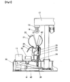
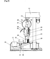
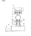
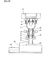
- FIGS. 5 to 8 are explanatory front views showing a series of raising and lowering movements of the figure 20 with showing an internal construction thereof.
- Figs. 9 and 10 are explanatory side views showing raising and lowering movements of the figure 20 and simultaneously showing the internal construction thereof.
- the figure 20 is made up of, as shown in Figs. 5 and 9 , a front body portion 25, a rear body portion 26, a mouth portion 21 having a mouth opening lever 22, a mouth opening/closing spring 29, a movable arm portion 27, a movable leg portion 28, a figure pedestal 24, and a cape 65.
- the figure 20 includes in an inside thereof an up/down moving member 23 which is supported by the rotating member 40 which performs a seesaw movement for raising and lowering the figure 20.
- the front body portion 25 is a member for forming a front surface of a main body of the figure 20.
- the front body portion 25 forms a front surface of the body and lower jawportion excluding arms and legs of the figure 20 which is formed into a shape representing the figure being looking up.
- the mouth opening/closing spring 29 is provided to an interior of the front body portion 25 at a portion representing an abdomen to be moved in response to the movement of the up/down moving member 23 and for biasing the mouth portion 21 to a closing side.
- the mouth opening/closing spring 29 is caught together with the interior of the abdomen of the front body portion 25 at its one end, and is caught together with an upper portion of the up/down moving member 23 on a side which faces the inside of the front body portion 25 at the other end.
- the rear body portion 26 is a member for forming a rear surface of a main body of the figure 20.
- the rear body portion 26 forms a rear surface of the body excluding the arms and the legs.
- a target guiding portion 63 is formed in a center of the rear body portion 26, which is a hole for guiding the target 18, which is described later, to outside of the figure 20.
- a lower end of the up/down moving member 23 is formed into rod-shaped and is supported by the rotating member 40.
- An upper end of the up/down moving member 23 is formed plate-shaped and is connected to the inside of the abdomen of the front body portion 25 via the mouth opening/closing spring 29 in the interior of the figure 20.
- the up/down moving member 23 includes an engaging portion 62 on an upper portion thereof which engages with a mouth opening lever 22 for opening the mouth portion 21, which is described later.
- the mouth portion 21 is formed on an upper portion of the figure 20 for representing a face portion of figure 20 excluding the lower jaw portion.
- the mouth portion 21 includes a mouth opening lever 22 for opening and closing the mouth portion on a portion which corresponds to a neck portion below an ear portion of the figure 20.
- an opening and closing mechanism of the mouth portion 21 will be described.
- the mouth opening lever 22 is engaged with the engaging portion 62 which positions on an upper portion of the up/down moving member 23. As shown in Fig. 6 , at the beginning of the moving up movement of the figure 20, the engaging portion 62 goes up slightly for moving the mouth opening lever 22 to upwards which is an opening side to thereby open the mouth portion 21.
- the engaging portion 62 is lowered slightly for moving the mouth opening lever 22 by biasing of the mouth opening/closing spring 29 to downwards which is a closing side to thereby close the mouth portion 21.
- the front body portion 25 and the rear body portion 26 form a hollow body of the figure 20.
- a figure pedestal 24 is disposed which is hollow and fixed on an upper surface of the housing 30, which is described later. Further, the up/down moving member 23 to be raised and lowered is disposed in the figure pedestal 24.
- Movable arm portions 27 form portions representing left and right arms on both sides of the figure 20, as shown in Fig. 9 .
- the movable arm portions 27 are formed in such a way as to be embedded between the rear body portion 26 and the front body portion 25.
- portions on the periphery of side portions of the movable arm portions 27 engage with upper engaging projections 61 and flat end portions on peripheries of the upper engaging portions 61 which are provided to the figure pedestal 24, which is described later, to thereby perform a motion of extending both arms while the up/down moving member 23 is raised.
- Movable leg portions 28 are formed into portions representing left and right legs on both sides of the figure 20, and are formed in such a way as to be embedded between the rear body portion 26 and the front body portion 25.
- inside ankle portions of the movable leg portions 28 engage with lower engaging projections 61 and flat end portions on peripheries of the lower engaging portions 61 which are provided to the figure pedestal 24, which is described later, to thereby perform a motion of opening and closing both legs while the up/down moving member 23 is raised.
- the figure pedestals 24 are disposed on the upper surface of the housing 30 of the game toy 10 by means of screws or the like for connecting.
- the figures 20 are disposed in predetermined positions by the figure pedestals 24.
- a lower portion of the figure pedestals 24 is a circular disc shape and the upper portion thereof is a rod shape to be inserted movably from between the legs into the inside of the figure 20.
- the engaging projections 61 and the flat end portions on peripheries of the engaging portions 61 described above are provided on the upper portion of the figure pedestal 24.
- the engaging projections 61 and the flat end portions on peripheries of the engaging portions 61 interfere the portions on the periphery of side portions of the movable arm portions 27 and a peripheries of the inside ankle portions of the movable leg portions 28, whereby the movable arm portions 27 extend both arms thereof and the movable leg portions 28 open and close both legs thereof while the figure 20 is raised.
- a cape 65 is formed at a position extending from a neck portion to a back portion of the figure 20 as an ornamental.
- the cape 65 is a part of a guiding portion which guides the target 18 to a predetermined position where is outside the figure 20 in conjunction with a target guiding portion 63 which is formed on the rear body portion 26.
- FIG. 5 A series of up and down movements of the figure 20 in the game toy 10 will be described by referring to the accompanying Figs. 5 to 10 .
- the figure 20 in the game toy 10 is in an initial state, as shown in Fig. 5 , provided the operating button 11 is not depressed.
- the figure 20 closes the mouth portion 21 in the initial state.
- the game top 10 is brought to a beginning state of the figure 20 being raised, as shown in Fig. 6 , just after the operating button 11 is depressed by a player.
- the figure 20 opens the mouth portion 21 first at the beginning state of being raised.
- the rotating member 40 performs a seesaw movement to a direction which raises the figure 20, whereby the up/down moving member 23 is raised which is supported by the rotating member 40.
- the mouth opening/closing spring 29 which is connected to the up/down moving member 23 is expanded and simultaneously the mouth opening lever 22 is moved to an opening side by the engaging portion 62 of the up/down moving member 23, whereby the mouth portion 21 is opened.
- the up/down moving member 23 When the operating button 11 is depressed further to bottom by the player, the up/down moving member 23 is raised higher to thereby support the front body portion 25, whereby the figure 20 is brought into a highest raising state where the main body of the figure 20 is raised to a highest position.
- the figure 20 attains a height at which the mouth portion 21 is enabled to hold the target 18 which is hung by the target catching portion 14 of the target tray 13.
- the player releases the operating button 11 in the highest raising state, whereby the figure 20 is brought into a beginning state of mouth closing, as shown in Fig. 7 .
- the rotating member 40 performs a seesaw movement to a direction which makes the figure 20 to be lowered, whereby the up/down moving member 23 which is supported by the rotating member 40 is lowered.
- the mouth opening/closing spring 29 which is connected to the up/down moving member 23 contracts and simultaneously the mouth opening lever 22 is moved to a closing side by the engaging portion 62 of the up/down moving member 23, whereby the mouth portion 21 is closed.
- the target 18 which is hung by the target catching portion 14 is interfered to thereby be caused to fall.
- the target 18 so fell is, as shown in Fig. 7 , conveyed into an interior of the figure 20.
- the figure 20 goes back to its initial position when the up/down moving member 23 is further lowered by a returning motion of the figure spring 39.
- the target 18 so conveyed into the interior of the figure 20 is guided through the hole of the target guiding portion 63 which is positioned in a center of the rear body portion 26 to the outside thereof, then is caused to fall onto the target connecting path 32 which positions a lower portion.
- each player makes the figure 20 up and down to thereby capture the target 18.
- the target catching portion 14 catches the target 18 in such a manner as to hang it which is stored in the target tray 13 in advance when the target 18 passes through a hole of the target tray 13, not shown, and subsequently falls.
- the target catching portions 14 are provided to three positions at 120 degree intervals about the rotating shaft 15 as a center.
- the target catching portion 14 is a thin plate material which is made of thermoplastic resin having resilience so that the target catching portion 14 is enabled to catch the target 18 and simultaneously to drop the target 18 when a small amount of force is exerted thereon.
- An inside of a distal end of the target catching portion 14 is formed into two hook shaped portions so as to pick the target 18 by the two hooks. Since the target catching portion 14 is thin, low strength, and exposed to outside, a protection cover or the like is provided to a periphery of the target catching portion 14 in such a manner as to not obstruct the fall of the target 18 to thereby be protected from external pressure.
- the depressing/releasing operation of the operating button 11 causes the target tray 13 to be rotated 60 degrees per each operation.
- the target catching portion 14 is disposed above either of the left or right figures 20.
- the plurality of spherically shaped targets 18 is guided to be disposed at a lower end of the target catching portion 14 sequentially by the rotation of the target tray 13 every time the target 18 is captured by the figure 20.
- a target storage tray 64 for storing the captured target 18 will be described. As shown in Figs. 1 or 10 , the target storage tray 64 is provided at the front surface of the game toy 10.
- the figure 20 is raised with opening the mouth portion 21, releases the target 18 from the hooks of the target catching portion 14 by closing the mouth portion 21 at the highest raising state and being lowered for conveying the target 18 into the mouth portion 21.
- the conveyed target 18 passes through the interior of the figure 20, via the target guiding portion 63 which positions in substantially a center of the rear body portion 26 of the figure 20, and falls onto the target connecting path 32 which is provided on the upper surface of the housing 30.
- the target storage tray 64 is a tray for storing the captured target 18.
- the game top 10 is not only a game toy with which a player can capture a target in a shape representing a ball or the like with ease, but also an educational tool which allows a player to learn such as counting the captured targets.
- an intellectual education tool as a game toy 10 which allows two players facing each other to have a chance to capture the target 18 alternately, whereby the players can keep their interests therein.
- figures 20 are arranged symmetrically on either side of the position of the rotating shaft 15 as a center, two players can compete against each other by operating each of the corresponding figures 20 for capturing the target 18, whereby the players can enjoy the game with excitement.
- the target tray 13 is designed so as to rotate and stop at a position where one of the target catching portions 14 corresponds to a position right above one of the figures 20, whereby two players can enjoy by capturing the target 18 alternately.
- the player can count the number of the captured target 18 with ease.
- the game toy 10 with applying a ball as a target 18 is described. However, by drawing a picture on a surface of the target 18 representing such as a bun, a hamburger, or a hotdog, the game toy 10 can be more realistic race game for the bun.
- the game toy 10 is not only a game toy with which a player can capture a target in a shape representing a ball or the like with ease, but also an educational tool which allows a player to learn such as counting the captured targets.
- an intellectual education tool as a game toy 10 which allows two players facing each other to have a chance to capture the target 18 alternately, whereby the players can keep their interests therein.
Landscapes
- Engineering & Computer Science (AREA)
- Multimedia (AREA)
- Toys (AREA)
Claims (5)
- Spielzeug (10) zum Erfassen eines Ziels (18), dessen Gestalt eine Kugel oder dergleichen darstellt, durch Betätigen mindestens eines Betätigungsknopfs (11) zum Anheben einer Figur (20) zum Erfassen des über der Figur gestützten Ziels durch Anheben der eine Gestalt wie etwa eine Puppe darstellenden Kugel, umfassend:mindestens eine Figur (20) undeine Zielwanne (13) zum Aufbewahren mehrerer der Ziele (18), deren Gestalten die Kugel oder dergleichen darstellen, die über der Figur (20) liegt; und gekennzeichnet durcheine sich drehende Welle (15) zum Stützen und Drehen der Zielwanne (13) undmindestens einen fangenden Abschnitt (14) zum Aufhängen eines Ziels (18), das in der Zielwanne (13) aufbewahrt wird;wobei die mindestens eine Figur (20) ausgelegt ist zum Öffnen ihres oberen Teils (21), während sie angehoben wird, während der Betätigungsknopf (11) gedrückt wird, und während der Betätigungsknopf (11) losgelassen wird, schließt die Figur (20) ihren oberen Teil (21), um das Ziel (18) von dem fangenden Abschnitt (14) zu erfassen, während er abgesenkt wird und auch die Zielwanne (13) um einen vorbestimmten Winkel gedreht wird.
- Spielzeug nach Anspruch 1, wobei die Figuren (20) zwei Figuren umfassen, die symmetrisch auf beiden Seiten der Position der sich drehenden Welle als Zentrum angeordnet sind und zwei der Betätigungsknöpfe (11) zum jeweiligen Betätigen jeder Figur vorgesehen sind.
- Spielzeug nach Anspruch 1 oder 2, dass, wenn eines der mehreren Ziele (18) durch die Figur erfasst wird, das andere in der Zielwanne aufbewahrte Ziel sich zu dem fangenden Abschnitt (14) bewegt, um dadurch aufgehängt zu werden.
- Spielzeug nach einem der vorhergehenden Ansprüche, wobei sich die fangenden Abschnitte (14) jeweils an drei Positionen an einem unteren Abschnitt der Zielwanne (13) befinden, die benachbart zu einer Peripherie davon in gleichen Abständen liegen und sich von dort nach unten erstrecken, und die Zielwanne so ausgelegt ist, dass sie sich dreht und an einer Position stoppt, wo einer der fangenden Abschnitte einer Position direkt über einer der Figuren (20) entspricht.
- Spielzeug nach einem der Ansprüche 1 bis 4, weiter umfassend eine Zielaufbewahrungswanne (64) zum Aufbewahren des von den Figuren (20) erfassten Ziels (18).
Applications Claiming Priority (1)
| Application Number | Priority Date | Filing Date | Title |
|---|---|---|---|
| JP2010165822A JP2012024335A (ja) | 2010-07-23 | 2010-07-23 | ゲーム玩具 |
Publications (2)
| Publication Number | Publication Date |
|---|---|
| EP2418007A1 EP2418007A1 (de) | 2012-02-15 |
| EP2418007B1 true EP2418007B1 (de) | 2013-08-28 |
Family
ID=44545522
Family Applications (1)
| Application Number | Title | Priority Date | Filing Date |
|---|---|---|---|
| EP11174870.3A Not-in-force EP2418007B1 (de) | 2010-07-23 | 2011-07-21 | Spielzeug |
Country Status (4)
| Country | Link |
|---|---|
| US (1) | US20120021666A1 (de) |
| EP (1) | EP2418007B1 (de) |
| JP (1) | JP2012024335A (de) |
| CN (1) | CN102371064A (de) |
Families Citing this family (4)
| Publication number | Priority date | Publication date | Assignee | Title |
|---|---|---|---|---|
| US20130305992A1 (en) * | 2011-02-04 | 2013-11-21 | Micro System Co., Ltd. | Rotating and holding apparatus for semiconductor substrate and conveying apparatus of rotating and holding apparatus for semiconductor substrate |
| CN105448162B (zh) * | 2016-01-07 | 2016-08-31 | 郑州职业技术学院 | 用于英语互动记忆的装置 |
| CN108364536B (zh) * | 2018-03-14 | 2021-07-23 | 吕艳男 | 一种专业学习设备 |
| WO2020251095A1 (ko) * | 2019-06-14 | 2020-12-17 | 엘지전자 주식회사 | 액션 로봇 |
Family Cites Families (56)
| Publication number | Priority date | Publication date | Assignee | Title |
|---|---|---|---|---|
| US996416A (en) * | 1910-08-04 | 1911-06-27 | Joseph B Kusnell | Toy. |
| US1636893A (en) * | 1925-03-24 | 1927-07-26 | Biberfeld Arthur | Ability game |
| US1572090A (en) * | 1925-04-27 | 1926-02-09 | Blue Bird Products Company | Vending machine |
| US3208751A (en) * | 1963-03-05 | 1965-09-28 | Kostka Charles | Game apparatus with ball dropping means and rotating target |
| US3583090A (en) * | 1968-10-14 | 1971-06-08 | Marvin Glass & Associates | Traveling toy tea table |
| US3970303A (en) * | 1975-06-19 | 1976-07-20 | Lawrence Peska Associates, Inc. | Game and toy apparatus |
| JPS5317901Y2 (de) * | 1975-07-04 | 1978-05-13 | ||
| US4149725A (en) * | 1977-04-23 | 1979-04-17 | Masatoshi Todokoro | Game board having animated ball projectors with retracting hoods and central target |
| JPS5549115Y2 (de) * | 1977-07-29 | 1980-11-15 | ||
| US4209940A (en) * | 1978-01-27 | 1980-07-01 | Marvin Glass & Associates | Toy ejector apparatus |
| JPS5555111Y2 (de) * | 1978-02-04 | 1980-12-19 | ||
| US4171133A (en) * | 1978-02-10 | 1979-10-16 | Marvin Glass & Associates | Self-propelled target toy |
| JPS563029Y2 (de) * | 1978-04-06 | 1981-01-23 | ||
| US4224761A (en) * | 1978-10-21 | 1980-09-30 | Kazuo Wakimura | Toy fishing play unit |
| US4223471A (en) * | 1978-12-13 | 1980-09-23 | Shelcore, Inc. | Aquarium crib toy |
| US4244568A (en) * | 1979-02-09 | 1981-01-13 | Marvin Glass & Associates | Game apparatus |
| JPS5641739Y2 (de) * | 1979-07-04 | 1981-09-30 | ||
| JPS614378Y2 (de) * | 1980-03-08 | 1986-02-10 | ||
| GB2091565B (en) * | 1981-01-22 | 1984-08-30 | Taiming Plastic Products Co Lt | Ball-retrieving game |
| US4412682A (en) * | 1982-02-10 | 1983-11-01 | Marvin Glass & Associates | Action game device |
| US4585235A (en) * | 1985-02-13 | 1986-04-29 | Williams Jerry D | Table ball game apparatus |
| US4603860A (en) * | 1985-05-07 | 1986-08-05 | Wey Shinn Hsiung | Toy of honey-gathering bee |
| JPH0541750Y2 (de) * | 1986-12-06 | 1993-10-21 | ||
| JPH0522230Y2 (de) * | 1986-12-06 | 1993-06-07 | ||
| JPH0541751Y2 (de) * | 1986-12-06 | 1993-10-21 | ||
| CN87203853U (zh) * | 1987-03-21 | 1988-01-20 | 满玉华 | 光环旋转玩具 |
| US4834373A (en) * | 1987-08-22 | 1989-05-30 | Chaun Tien Chuang | Fishing toy |
| JPH0180188U (de) * | 1987-11-19 | 1989-05-30 | ||
| JPH0538791Y2 (de) * | 1988-04-15 | 1993-09-30 | ||
| US4936574A (en) * | 1988-09-21 | 1990-06-26 | Lee Ching H | Fishing fish toy |
| JPH0630227Y2 (ja) * | 1989-03-10 | 1994-08-17 | 有限会社あつぷる | ゲーム器 |
| US5009418A (en) * | 1989-05-25 | 1991-04-23 | Chuan Tien Chuang | Toy including fishing game and passive game elements |
| JPH0341323A (ja) | 1989-07-10 | 1991-02-21 | Canon Inc | 光検出方法および半導体光センサーic |
| US5163863A (en) * | 1991-02-08 | 1992-11-17 | Adolph E. Goldfarb | Action toy |
| US5193819A (en) * | 1992-01-30 | 1993-03-16 | Chen Tsan Ling | Doll catching toy |
| JP3271781B2 (ja) * | 1992-02-17 | 2002-04-08 | 株式会社センテクリエイションズ | ゲーム玩具用駆動装置 |
| US5335917A (en) * | 1993-01-13 | 1994-08-09 | Hasbro, Inc. | Game apparatus and motorized bucket assembly therefore |
| JPH08206353A (ja) | 1995-02-02 | 1996-08-13 | Sente Creations:Kk | 対面式ゲーム玩具 |
| JP2814365B2 (ja) * | 1995-08-28 | 1998-10-22 | コナミ株式会社 | 景品獲得ゲーム機 |
| US5609341A (en) * | 1996-03-11 | 1997-03-11 | Chuang; Chuan-Tien | Sight-designed fishing game toy |
| US5759083A (en) * | 1997-01-24 | 1998-06-02 | Soma International Ltd. | Toy vehicle with integral ball playing apparatus |
| US5887872A (en) * | 1997-08-19 | 1999-03-30 | Mattel, Inc. | Memory game having sequentially opened capsules |
| US6164653A (en) * | 1999-05-12 | 2000-12-26 | Chuang; Chuan-Tien | Fishing toy structure |
| US6695698B1 (en) * | 2000-07-26 | 2004-02-24 | Pixy Games, Inc. | Electro-mechanical coin operated capsule dispensing game system |
| US6464504B1 (en) * | 2001-09-24 | 2002-10-15 | Diane Wingert | Mathematical game of amusement |
| US6899337B2 (en) * | 2002-02-01 | 2005-05-31 | Win ‘n’ Grin Amusements Pty Ltd. | Crane amusement game |
| US7334798B2 (en) * | 2002-09-18 | 2008-02-26 | Benchmark Entertainment L.C. | Crane amusement game with vertically adjustable play field |
| US6837769B1 (en) * | 2003-04-28 | 2005-01-04 | Interlego Ag | Toy figure and a game comprising such toy figure |
| WO2005000415A2 (en) * | 2003-06-06 | 2005-01-06 | Mattel, Inc. | Mechanized ball-throwing game |
| US20050017457A1 (en) * | 2003-07-22 | 2005-01-27 | Brian Dubinsky | Inflatable balancing game |
| US7080840B1 (en) * | 2005-04-30 | 2006-07-25 | Yu-Hsiang Chen | Grabber machine with enhanced design |
| US7168702B1 (en) * | 2005-07-19 | 2007-01-30 | Shoemaker Stephen P | Amusement device of skill and lottery |
| JP4787124B2 (ja) * | 2006-10-12 | 2011-10-05 | 株式会社アガツマ | 家庭用クレーンゲーム機 |
| FR2934502A1 (fr) * | 2008-07-29 | 2010-02-05 | Nico Roosendaal | Dispositif distributeur a fonction ludique. |
| CN201431768Y (zh) * | 2009-06-04 | 2010-03-31 | 马达飞 | 一种木制玩具 |
| US8181964B2 (en) * | 2010-04-23 | 2012-05-22 | Mattel, Inc. | Game |
-
2010
- 2010-07-23 JP JP2010165822A patent/JP2012024335A/ja active Pending
-
2011
- 2011-07-19 US US13/186,318 patent/US20120021666A1/en not_active Abandoned
- 2011-07-21 EP EP11174870.3A patent/EP2418007B1/de not_active Not-in-force
- 2011-07-22 CN CN2011102167299A patent/CN102371064A/zh active Pending
Also Published As
| Publication number | Publication date |
|---|---|
| CN102371064A (zh) | 2012-03-14 |
| EP2418007A1 (de) | 2012-02-15 |
| JP2012024335A (ja) | 2012-02-09 |
| US20120021666A1 (en) | 2012-01-26 |
Similar Documents
| Publication | Publication Date | Title |
|---|---|---|
| CN102131558B (zh) | 动作玩具 | |
| US20100304873A1 (en) | Bowling Ball and Football Game Controller | |
| US8087671B2 (en) | Spatial puzzle apparatus | |
| EP2418007B1 (de) | Spielzeug | |
| JP4669580B2 (ja) | ゲームシステム | |
| JP4698538B2 (ja) | 玩具 | |
| KR950003252B1 (ko) | 레슬링선수인형 | |
| US4826160A (en) | Action toy game apparatus | |
| HK1168062A (en) | Game toy | |
| US3432961A (en) | Animated jigsaw puzzle toy | |
| US4025074A (en) | Mini-dome basketball game | |
| CN210473034U (zh) | 一种玩偶 | |
| JP2012228494A (ja) | 飛び上り玩具 | |
| JP3751626B2 (ja) | ゲーム装置 | |
| JP2008067882A (ja) | 装着具 | |
| KR101678118B1 (ko) | 공놀이 장치 | |
| JP7305149B2 (ja) | 家庭用クレーンゲーム機 | |
| JP6788048B2 (ja) | 回転玩具 | |
| JP3751627B2 (ja) | ゲーム装置 | |
| KR100540751B1 (ko) | 탑승자에 의한 흔들림을 이용하는 놀이기구 | |
| GB2343126A (en) | Figure toy | |
| JP3002905U (ja) | 景品パックンゲーム機 | |
| JP3239101B2 (ja) | 釣り上げゲーム | |
| JPH0734889U (ja) | 弾き玩具 | |
| JP3173811U (ja) | 玩具 |
Legal Events
| Date | Code | Title | Description |
|---|---|---|---|
| AK | Designated contracting states |
Kind code of ref document: A1 Designated state(s): AL AT BE BG CH CY CZ DE DK EE ES FI FR GB GR HR HU IE IS IT LI LT LU LV MC MK MT NL NO PL PT RO RS SE SI SK SM TR |
|
| AX | Request for extension of the european patent |
Extension state: BA ME |
|
| PUAI | Public reference made under article 153(3) epc to a published international application that has entered the european phase |
Free format text: ORIGINAL CODE: 0009012 |
|
| 17P | Request for examination filed |
Effective date: 20120814 |
|
| GRAP | Despatch of communication of intention to grant a patent |
Free format text: ORIGINAL CODE: EPIDOSNIGR1 |
|
| GRAS | Grant fee paid |
Free format text: ORIGINAL CODE: EPIDOSNIGR3 |
|
| GRAA | (expected) grant |
Free format text: ORIGINAL CODE: 0009210 |
|
| AK | Designated contracting states |
Kind code of ref document: B1 Designated state(s): AL AT BE BG CH CY CZ DE DK EE ES FI FR GB GR HR HU IE IS IT LI LT LU LV MC MK MT NL NO PL PT RO RS SE SI SK SM TR |
|
| REG | Reference to a national code |
Ref country code: GB Ref legal event code: FG4D |
|
| REG | Reference to a national code |
Ref country code: CH Ref legal event code: EP |
|
| REG | Reference to a national code |
Ref country code: AT Ref legal event code: REF Ref document number: 628955 Country of ref document: AT Kind code of ref document: T Effective date: 20130915 |
|
| REG | Reference to a national code |
Ref country code: IE Ref legal event code: FG4D |
|
| REG | Reference to a national code |
Ref country code: DE Ref legal event code: R096 Ref document number: 602011002810 Country of ref document: DE Effective date: 20131024 |
|
| REG | Reference to a national code |
Ref country code: AT Ref legal event code: MK05 Ref document number: 628955 Country of ref document: AT Kind code of ref document: T Effective date: 20130828 |
|
| REG | Reference to a national code |
Ref country code: LT Ref legal event code: MG4D |
|
| REG | Reference to a national code |
Ref country code: NL Ref legal event code: VDEP Effective date: 20130828 |
|
| PG25 | Lapsed in a contracting state [announced via postgrant information from national office to epo] |
Ref country code: CY Free format text: LAPSE BECAUSE OF FAILURE TO SUBMIT A TRANSLATION OF THE DESCRIPTION OR TO PAY THE FEE WITHIN THE PRESCRIBED TIME-LIMIT Effective date: 20130814 Ref country code: SE Free format text: LAPSE BECAUSE OF FAILURE TO SUBMIT A TRANSLATION OF THE DESCRIPTION OR TO PAY THE FEE WITHIN THE PRESCRIBED TIME-LIMIT Effective date: 20130828 Ref country code: PT Free format text: LAPSE BECAUSE OF FAILURE TO SUBMIT A TRANSLATION OF THE DESCRIPTION OR TO PAY THE FEE WITHIN THE PRESCRIBED TIME-LIMIT Effective date: 20131230 Ref country code: AT Free format text: LAPSE BECAUSE OF FAILURE TO SUBMIT A TRANSLATION OF THE DESCRIPTION OR TO PAY THE FEE WITHIN THE PRESCRIBED TIME-LIMIT Effective date: 20130828 Ref country code: LT Free format text: LAPSE BECAUSE OF FAILURE TO SUBMIT A TRANSLATION OF THE DESCRIPTION OR TO PAY THE FEE WITHIN THE PRESCRIBED TIME-LIMIT Effective date: 20130828 Ref country code: IS Free format text: LAPSE BECAUSE OF FAILURE TO SUBMIT A TRANSLATION OF THE DESCRIPTION OR TO PAY THE FEE WITHIN THE PRESCRIBED TIME-LIMIT Effective date: 20131228 Ref country code: NO Free format text: LAPSE BECAUSE OF FAILURE TO SUBMIT A TRANSLATION OF THE DESCRIPTION OR TO PAY THE FEE WITHIN THE PRESCRIBED TIME-LIMIT Effective date: 20131128 Ref country code: HR Free format text: LAPSE BECAUSE OF FAILURE TO SUBMIT A TRANSLATION OF THE DESCRIPTION OR TO PAY THE FEE WITHIN THE PRESCRIBED TIME-LIMIT Effective date: 20130828 |
|
| REG | Reference to a national code |
Ref country code: NL Ref legal event code: VDEP Effective date: 20130828 |
|
| PG25 | Lapsed in a contracting state [announced via postgrant information from national office to epo] |
Ref country code: SI Free format text: LAPSE BECAUSE OF FAILURE TO SUBMIT A TRANSLATION OF THE DESCRIPTION OR TO PAY THE FEE WITHIN THE PRESCRIBED TIME-LIMIT Effective date: 20130828 Ref country code: FI Free format text: LAPSE BECAUSE OF FAILURE TO SUBMIT A TRANSLATION OF THE DESCRIPTION OR TO PAY THE FEE WITHIN THE PRESCRIBED TIME-LIMIT Effective date: 20130828 Ref country code: BE Free format text: LAPSE BECAUSE OF FAILURE TO SUBMIT A TRANSLATION OF THE DESCRIPTION OR TO PAY THE FEE WITHIN THE PRESCRIBED TIME-LIMIT Effective date: 20130828 Ref country code: LV Free format text: LAPSE BECAUSE OF FAILURE TO SUBMIT A TRANSLATION OF THE DESCRIPTION OR TO PAY THE FEE WITHIN THE PRESCRIBED TIME-LIMIT Effective date: 20130828 Ref country code: PL Free format text: LAPSE BECAUSE OF FAILURE TO SUBMIT A TRANSLATION OF THE DESCRIPTION OR TO PAY THE FEE WITHIN THE PRESCRIBED TIME-LIMIT Effective date: 20130828 Ref country code: GR Free format text: LAPSE BECAUSE OF FAILURE TO SUBMIT A TRANSLATION OF THE DESCRIPTION OR TO PAY THE FEE WITHIN THE PRESCRIBED TIME-LIMIT Effective date: 20131129 |
|
| PG25 | Lapsed in a contracting state [announced via postgrant information from national office to epo] |
Ref country code: CY Free format text: LAPSE BECAUSE OF FAILURE TO SUBMIT A TRANSLATION OF THE DESCRIPTION OR TO PAY THE FEE WITHIN THE PRESCRIBED TIME-LIMIT Effective date: 20130828 |
|
| PG25 | Lapsed in a contracting state [announced via postgrant information from national office to epo] |
Ref country code: RO Free format text: LAPSE BECAUSE OF FAILURE TO SUBMIT A TRANSLATION OF THE DESCRIPTION OR TO PAY THE FEE WITHIN THE PRESCRIBED TIME-LIMIT Effective date: 20130828 Ref country code: NL Free format text: LAPSE BECAUSE OF FAILURE TO SUBMIT A TRANSLATION OF THE DESCRIPTION OR TO PAY THE FEE WITHIN THE PRESCRIBED TIME-LIMIT Effective date: 20130828 Ref country code: SK Free format text: LAPSE BECAUSE OF FAILURE TO SUBMIT A TRANSLATION OF THE DESCRIPTION OR TO PAY THE FEE WITHIN THE PRESCRIBED TIME-LIMIT Effective date: 20130828 Ref country code: CZ Free format text: LAPSE BECAUSE OF FAILURE TO SUBMIT A TRANSLATION OF THE DESCRIPTION OR TO PAY THE FEE WITHIN THE PRESCRIBED TIME-LIMIT Effective date: 20130828 Ref country code: DK Free format text: LAPSE BECAUSE OF FAILURE TO SUBMIT A TRANSLATION OF THE DESCRIPTION OR TO PAY THE FEE WITHIN THE PRESCRIBED TIME-LIMIT Effective date: 20130828 Ref country code: EE Free format text: LAPSE BECAUSE OF FAILURE TO SUBMIT A TRANSLATION OF THE DESCRIPTION OR TO PAY THE FEE WITHIN THE PRESCRIBED TIME-LIMIT Effective date: 20130828 |
|
| PG25 | Lapsed in a contracting state [announced via postgrant information from national office to epo] |
Ref country code: ES Free format text: LAPSE BECAUSE OF FAILURE TO SUBMIT A TRANSLATION OF THE DESCRIPTION OR TO PAY THE FEE WITHIN THE PRESCRIBED TIME-LIMIT Effective date: 20130828 Ref country code: IT Free format text: LAPSE BECAUSE OF FAILURE TO SUBMIT A TRANSLATION OF THE DESCRIPTION OR TO PAY THE FEE WITHIN THE PRESCRIBED TIME-LIMIT Effective date: 20130828 |
|
| REG | Reference to a national code |
Ref country code: DE Ref legal event code: R097 Ref document number: 602011002810 Country of ref document: DE |
|
| PLBE | No opposition filed within time limit |
Free format text: ORIGINAL CODE: 0009261 |
|
| STAA | Information on the status of an ep patent application or granted ep patent |
Free format text: STATUS: NO OPPOSITION FILED WITHIN TIME LIMIT |
|
| 26N | No opposition filed |
Effective date: 20140530 |
|
| REG | Reference to a national code |
Ref country code: DE Ref legal event code: R097 Ref document number: 602011002810 Country of ref document: DE Effective date: 20140530 |
|
| PGFP | Annual fee paid to national office [announced via postgrant information from national office to epo] |
Ref country code: DE Payment date: 20140716 Year of fee payment: 4 |
|
| PGFP | Annual fee paid to national office [announced via postgrant information from national office to epo] |
Ref country code: FR Payment date: 20140708 Year of fee payment: 4 |
|
| PG25 | Lapsed in a contracting state [announced via postgrant information from national office to epo] |
Ref country code: LU Free format text: LAPSE BECAUSE OF FAILURE TO SUBMIT A TRANSLATION OF THE DESCRIPTION OR TO PAY THE FEE WITHIN THE PRESCRIBED TIME-LIMIT Effective date: 20140721 |
|
| REG | Reference to a national code |
Ref country code: CH Ref legal event code: PL |
|
| REG | Reference to a national code |
Ref country code: IE Ref legal event code: MM4A |
|
| PG25 | Lapsed in a contracting state [announced via postgrant information from national office to epo] |
Ref country code: LI Free format text: LAPSE BECAUSE OF NON-PAYMENT OF DUE FEES Effective date: 20140731 Ref country code: CH Free format text: LAPSE BECAUSE OF NON-PAYMENT OF DUE FEES Effective date: 20140731 |
|
| PG25 | Lapsed in a contracting state [announced via postgrant information from national office to epo] |
Ref country code: IE Free format text: LAPSE BECAUSE OF NON-PAYMENT OF DUE FEES Effective date: 20140721 |
|
| REG | Reference to a national code |
Ref country code: DE Ref legal event code: R119 Ref document number: 602011002810 Country of ref document: DE |
|
| GBPC | Gb: european patent ceased through non-payment of renewal fee |
Effective date: 20150721 |
|
| PG25 | Lapsed in a contracting state [announced via postgrant information from national office to epo] |
Ref country code: MC Free format text: LAPSE BECAUSE OF FAILURE TO SUBMIT A TRANSLATION OF THE DESCRIPTION OR TO PAY THE FEE WITHIN THE PRESCRIBED TIME-LIMIT Effective date: 20130828 Ref country code: SM Free format text: LAPSE BECAUSE OF FAILURE TO SUBMIT A TRANSLATION OF THE DESCRIPTION OR TO PAY THE FEE WITHIN THE PRESCRIBED TIME-LIMIT Effective date: 20130828 Ref country code: GB Free format text: LAPSE BECAUSE OF NON-PAYMENT OF DUE FEES Effective date: 20150721 Ref country code: DE Free format text: LAPSE BECAUSE OF NON-PAYMENT OF DUE FEES Effective date: 20160202 |
|
| REG | Reference to a national code |
Ref country code: FR Ref legal event code: ST Effective date: 20160331 |
|
| PG25 | Lapsed in a contracting state [announced via postgrant information from national office to epo] |
Ref country code: FR Free format text: LAPSE BECAUSE OF NON-PAYMENT OF DUE FEES Effective date: 20150731 |
|
| PG25 | Lapsed in a contracting state [announced via postgrant information from national office to epo] |
Ref country code: RS Free format text: LAPSE BECAUSE OF NON-PAYMENT OF DUE FEES Effective date: 20130828 Ref country code: BG Free format text: LAPSE BECAUSE OF FAILURE TO SUBMIT A TRANSLATION OF THE DESCRIPTION OR TO PAY THE FEE WITHIN THE PRESCRIBED TIME-LIMIT Effective date: 20130828 Ref country code: MT Free format text: LAPSE BECAUSE OF FAILURE TO SUBMIT A TRANSLATION OF THE DESCRIPTION OR TO PAY THE FEE WITHIN THE PRESCRIBED TIME-LIMIT Effective date: 20130828 |
|
| PG25 | Lapsed in a contracting state [announced via postgrant information from national office to epo] |
Ref country code: TR Free format text: LAPSE BECAUSE OF FAILURE TO SUBMIT A TRANSLATION OF THE DESCRIPTION OR TO PAY THE FEE WITHIN THE PRESCRIBED TIME-LIMIT Effective date: 20130828 Ref country code: HU Free format text: LAPSE BECAUSE OF FAILURE TO SUBMIT A TRANSLATION OF THE DESCRIPTION OR TO PAY THE FEE WITHIN THE PRESCRIBED TIME-LIMIT; INVALID AB INITIO Effective date: 20110721 |
|
| PG25 | Lapsed in a contracting state [announced via postgrant information from national office to epo] |
Ref country code: MK Free format text: LAPSE BECAUSE OF FAILURE TO SUBMIT A TRANSLATION OF THE DESCRIPTION OR TO PAY THE FEE WITHIN THE PRESCRIBED TIME-LIMIT Effective date: 20130828 |
|
| PG25 | Lapsed in a contracting state [announced via postgrant information from national office to epo] |
Ref country code: AL Free format text: LAPSE BECAUSE OF FAILURE TO SUBMIT A TRANSLATION OF THE DESCRIPTION OR TO PAY THE FEE WITHIN THE PRESCRIBED TIME-LIMIT Effective date: 20130828 |