EP2418517A2 - Capteur optoélectronique - Google Patents
Capteur optoélectronique Download PDFInfo
- Publication number
- EP2418517A2 EP2418517A2 EP11006272A EP11006272A EP2418517A2 EP 2418517 A2 EP2418517 A2 EP 2418517A2 EP 11006272 A EP11006272 A EP 11006272A EP 11006272 A EP11006272 A EP 11006272A EP 2418517 A2 EP2418517 A2 EP 2418517A2
- Authority
- EP
- European Patent Office
- Prior art keywords
- sensor
- wing
- wing system
- detection area
- image
- Prior art date
- Legal status (The legal status is an assumption and is not a legal conclusion. Google has not performed a legal analysis and makes no representation as to the accuracy of the status listed.)
- Withdrawn
Links
Images










Classifications
-
- G—PHYSICS
- G01—MEASURING; TESTING
- G01V—GEOPHYSICS; GRAVITATIONAL MEASUREMENTS; DETECTING MASSES OR OBJECTS; TAGS
- G01V8/00—Prospecting or detecting by optical means
- G01V8/10—Detecting, e.g. by using light barriers
- G01V8/20—Detecting, e.g. by using light barriers using multiple transmitters or receivers
-
- E—FIXED CONSTRUCTIONS
- E05—LOCKS; KEYS; WINDOW OR DOOR FITTINGS; SAFES
- E05F—DEVICES FOR MOVING WINGS INTO OPEN OR CLOSED POSITION; CHECKS FOR WINGS; WING FITTINGS NOT OTHERWISE PROVIDED FOR, CONCERNED WITH THE FUNCTIONING OF THE WING
- E05F15/00—Power-operated mechanisms for wings
- E05F15/70—Power-operated mechanisms for wings with automatic actuation
- E05F15/73—Power-operated mechanisms for wings with automatic actuation responsive to movement or presence of persons or objects
- E05F15/74—Power-operated mechanisms for wings with automatic actuation responsive to movement or presence of persons or objects using photoelectric cells
-
- G—PHYSICS
- G01—MEASURING; TESTING
- G01S—RADIO DIRECTION-FINDING; RADIO NAVIGATION; DETERMINING DISTANCE OR VELOCITY BY USE OF RADIO WAVES; LOCATING OR PRESENCE-DETECTING BY USE OF THE REFLECTION OR RERADIATION OF RADIO WAVES; ANALOGOUS ARRANGEMENTS USING OTHER WAVES
- G01S17/00—Systems using the reflection or reradiation of electromagnetic waves other than radio waves, e.g. lidar systems
- G01S17/02—Systems using the reflection of electromagnetic waves other than radio waves
- G01S17/06—Systems determining position data of a target
- G01S17/08—Systems determining position data of a target for measuring distance only
- G01S17/10—Systems determining position data of a target for measuring distance only using transmission of interrupted, pulse-modulated waves
-
- G—PHYSICS
- G01—MEASURING; TESTING
- G01S—RADIO DIRECTION-FINDING; RADIO NAVIGATION; DETERMINING DISTANCE OR VELOCITY BY USE OF RADIO WAVES; LOCATING OR PRESENCE-DETECTING BY USE OF THE REFLECTION OR RERADIATION OF RADIO WAVES; ANALOGOUS ARRANGEMENTS USING OTHER WAVES
- G01S17/00—Systems using the reflection or reradiation of electromagnetic waves other than radio waves, e.g. lidar systems
- G01S17/88—Lidar systems specially adapted for specific applications
-
- E—FIXED CONSTRUCTIONS
- E05—LOCKS; KEYS; WINDOW OR DOOR FITTINGS; SAFES
- E05F—DEVICES FOR MOVING WINGS INTO OPEN OR CLOSED POSITION; CHECKS FOR WINGS; WING FITTINGS NOT OTHERWISE PROVIDED FOR, CONCERNED WITH THE FUNCTIONING OF THE WING
- E05F15/00—Power-operated mechanisms for wings
- E05F15/70—Power-operated mechanisms for wings with automatic actuation
- E05F15/73—Power-operated mechanisms for wings with automatic actuation responsive to movement or presence of persons or objects
- E05F2015/765—Power-operated mechanisms for wings with automatic actuation responsive to movement or presence of persons or objects using optical sensors
-
- E—FIXED CONSTRUCTIONS
- E05—LOCKS; KEYS; WINDOW OR DOOR FITTINGS; SAFES
- E05Y—INDEXING SCHEME ASSOCIATED WITH SUBCLASSES E05D AND E05F, RELATING TO CONSTRUCTION ELEMENTS, ELECTRIC CONTROL, POWER SUPPLY, POWER SIGNAL OR TRANSMISSION, USER INTERFACES, MOUNTING OR COUPLING, DETAILS, ACCESSORIES, AUXILIARY OPERATIONS NOT OTHERWISE PROVIDED FOR, APPLICATION THEREOF
- E05Y2400/00—Electronic control; Electrical power; Power supply; Power or signal transmission; User interfaces
- E05Y2400/10—Electronic control
- E05Y2400/32—Position control, detection or monitoring
-
- E—FIXED CONSTRUCTIONS
- E05—LOCKS; KEYS; WINDOW OR DOOR FITTINGS; SAFES
- E05Y—INDEXING SCHEME ASSOCIATED WITH SUBCLASSES E05D AND E05F, RELATING TO CONSTRUCTION ELEMENTS, ELECTRIC CONTROL, POWER SUPPLY, POWER SIGNAL OR TRANSMISSION, USER INTERFACES, MOUNTING OR COUPLING, DETAILS, ACCESSORIES, AUXILIARY OPERATIONS NOT OTHERWISE PROVIDED FOR, APPLICATION THEREOF
- E05Y2400/00—Electronic control; Electrical power; Power supply; Power or signal transmission; User interfaces
- E05Y2400/10—Electronic control
- E05Y2400/40—Control units therefor
-
- E—FIXED CONSTRUCTIONS
- E05—LOCKS; KEYS; WINDOW OR DOOR FITTINGS; SAFES
- E05Y—INDEXING SCHEME ASSOCIATED WITH SUBCLASSES E05D AND E05F, RELATING TO CONSTRUCTION ELEMENTS, ELECTRIC CONTROL, POWER SUPPLY, POWER SIGNAL OR TRANSMISSION, USER INTERFACES, MOUNTING OR COUPLING, DETAILS, ACCESSORIES, AUXILIARY OPERATIONS NOT OTHERWISE PROVIDED FOR, APPLICATION THEREOF
- E05Y2400/00—Electronic control; Electrical power; Power supply; Power or signal transmission; User interfaces
- E05Y2400/10—Electronic control
- E05Y2400/44—Sensors not directly associated with the wing movement
-
- E—FIXED CONSTRUCTIONS
- E05—LOCKS; KEYS; WINDOW OR DOOR FITTINGS; SAFES
- E05Y—INDEXING SCHEME ASSOCIATED WITH SUBCLASSES E05D AND E05F, RELATING TO CONSTRUCTION ELEMENTS, ELECTRIC CONTROL, POWER SUPPLY, POWER SIGNAL OR TRANSMISSION, USER INTERFACES, MOUNTING OR COUPLING, DETAILS, ACCESSORIES, AUXILIARY OPERATIONS NOT OTHERWISE PROVIDED FOR, APPLICATION THEREOF
- E05Y2400/00—Electronic control; Electrical power; Power supply; Power or signal transmission; User interfaces
- E05Y2400/10—Electronic control
- E05Y2400/45—Control modes
- E05Y2400/452—Control modes for saving energy, e.g. sleep or wake-up
-
- G—PHYSICS
- G01—MEASURING; TESTING
- G01S—RADIO DIRECTION-FINDING; RADIO NAVIGATION; DETERMINING DISTANCE OR VELOCITY BY USE OF RADIO WAVES; LOCATING OR PRESENCE-DETECTING BY USE OF THE REFLECTION OR RERADIATION OF RADIO WAVES; ANALOGOUS ARRANGEMENTS USING OTHER WAVES
- G01S7/00—Details of systems according to groups G01S13/00, G01S15/00, G01S17/00
- G01S7/48—Details of systems according to groups G01S13/00, G01S15/00, G01S17/00 of systems according to group G01S17/00
- G01S7/497—Means for monitoring or calibrating
Definitions
- the invention relates to a door system sensor and thus equipped wing systems, in particular designed as door systems. Furthermore, the invention relates to a method for operating such sensors or wing systems.
- Sealed wing systems are known per se. There are different types of sensors.
- activation sensors that are set up to strike due to certain conditions in the monitored coverage area or just not. So these are sensors with only two operating or switching states.
- Known sensors are motion detectors and infrared sensors. Such sensors have a design-related disadvantage, they can not distinguish between safety-related objects such as persons and non-safety-related objects such as a heated floor.
- the term objects includes both objects and living beings or parts of them, such as a person's finger.
- Another type of sensors are so-called motion sensors. Ie. they detect the movement of objects using the well-known Doppler effect. Not or very slowly moving and / or very small objects can not usually be detected. Although the direction of a moving, detectable object can be determined with radar sensors with multiple penetrations, but only rough. This is not sufficient for wing systems, especially in the detection range of the safety sensors.
- sensors have been developed which detect an image of the detection area to be monitored and thus enable recognition of the objects present therein and also their direction of movement. This makes it possible to avoid the aforementioned disadvantages.
- Such sensors require, in addition to image processing logic, a set of individual sensors which detect respective pixels of an image of the detection area to be monitored thus formed by the sensor.
- Laser scanners which optically deflect emitted and incident laser light by means of at least one mirror. Predetermined measuring points of the environment to be imaged are scanned one after the other.
- the disadvantage is the need for a mechanically adjustable mirror.
- the necessary for scanning pivoting of the mirror about two axes makes the structural design and control very expensive.
- Matrix 400 TM it is proposed to couple this scanner sensor to an external trigger or activation sensor so that the scanner sensor does not have to be active all the time. As a result, its energy consumption is reduced over time. However, when activated, the sensor will always monitor the entire coverage area to be monitored, requiring full energy coverage throughout the activation.
- the object of the invention is to reduce the aforementioned disadvantages or even eliminate them.
- a sensor according to the invention is set up to be arranged in the detection range of a wing system such that it sensory covers a predetermined detection area to be monitored with respect to the wing system.
- This detection area is, for example, a detection area swept by a wing of the wing system as it moves.
- the sensor is designed as an image acquisition sensor. Ie. it forms an image of the coverage area to be monitored.
- the sensor has at least two photosensitive sensor elements which are arranged in such a way that they completely cover the detection area to be monitored. The light values detected by the activated sensor elements together thus result in a respective image captured by the sensor.
- the sensor has a control device or is coupled to it.
- the control device is inventively provided to activate or inactivate predetermined sensor elements of the sensor according to a respective current state of the wing system. For example, if the wing in question is not moved, its environment need not be monitored. Ie. Here all sensor elements can be deactivated. However, if it is closed, its main closing edge, ie the edge which is moved in the direction of the corresponding edge of a wing surround or the like, poses a potential danger. As long as the main closing edge has a distance to the corresponding edge such that jamming, for example, of a person is hardly to be feared is, some of the sensor elements may remain inactivated. Although the activated sensor elements continue to monitor the range of movement of the wing, but in much coarser resolution.
- the inactivated sensor elements are activated. This has the advantage that, unless something unusual happens, the sensor is only partially activated over most of the wing travel and thus consumes less energy than if it were always fully activated.
- the sensor elements are arranged like a matrix. This allows a technically simple image data processing.
- the senor according to the invention has at least one energy-saving mode and one active mode.
- energy-saving mode only a part of the sensor elements of the sensor is activated, whereas in active mode all sensor elements covering the respective detection area to be monitored are activated.
- Mode switching allows the activation or deactivation of groups of sensor elements, which simplifies the interconnection. It is possible to pre-define sensor element groups for the operating modes by way of example on the software side.
- the sensor preferably has or is coupled to a data processing device.
- the data processing device is set up to match the image captured by the sensor elements with predetermined, stored patterns that correspond to non-safety-relevant parts of the wing system itself or its surroundings.
- the sensor can be designed as a clocked operated sensor. In that case, the operating clock of the sensor is less in the inactive mode than in the active mode.
- the senor further comprises a lighting device.
- the illumination device is set up to illuminate the detection area to be monitored in such a way that the sensor elements are able to detect the above-mentioned light values.
- the illumination device provides a reduced illumination compared to the active mode. This can be done by not lighting all the lighting elements of the lighting device and / or supplying the operated lighting elements with reduced energy. This allows an additional optimization of the sensor with respect to the energy requirement over time.
- the sensor preferably also has a sleep mode, in which all the sensor elements that cover a detection area outside of a predetermined, safety-relevant detection area of the wing installation are inactivated.
- the safety-relevant detection range can be zero in the case of a stationary leaf in the fully open position or the closed position, that is, it does not exist at all. In partial open position, provision may be made for the safety-relevant detection area to be formed by means of a narrow detection area surrounding the wing, which under certain circumstances has nothing to do with the aforementioned detection area to be monitored. If, for example, a person enters the safety-relevant detection area, it can be provided to move the sash away from this person and to bring the sensor into the energy-saving or active mode accordingly.
- the sensor has a wake-up device or is coupled to such. The waking device brings the sensor into the energy-saving mode or active mode when actuated or triggered.
- the wake-up device may comprise an activation sensor covering the safety-related detection area.
- Object in the safety-relevant detection range brings the activation sensor sensor of the invention in the active mode.
- Passive sensors such as motion detectors or active sensors such as active infrared sensors can be used as the activation sensor.
- the wake-up device comprises a switching device which is set to switch the sensor into the active mode or inactivated or sleep mode upon activation or deactivation or deactivation.
- a switching device may be a wing or door drive control, which detects a movement of the output shaft of the door drive, for example by means of an incremental encoder upon pressing a person against the wing in a direction of movement and then causes the drive to (continue) to the wing in this direction move. It can also be formed by means of a touch-sensitive switch.
- a wing system according to the invention has at least one of the above-described sensors.
- This type of sensor can be used in all possible modes of operation such as safety sensor, safety edge, in fire detectors, opening sensor, closing sensor, closing edge monitoring.
- the at least one sensor of the wing system preferably monitors a region of an end edge or closing edge of an associated wing of the wing system, which also extends away from the associated wing.
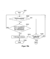
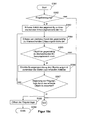
- a method for operating this wing system which initially comprises steps of starting and initializing the wing system. Then, according to the invention, at least one first sensor is put into the energy-saving mode and initially operated in this mode. It will then be checked if this sensor is waking up or not. If it does not wake up, it will jump back to this test step according to the known polling mechanism. Otherwise, the relevant sensor will continue to operate in active mode. This prevents that the sensor in question is constantly in full readiness and thus requires relatively much energy.
- the energy-saving mode allows the operation of this sensor, for example, as an activation sensor or as an image sensor with a coarser resolution, that is, not all individual sensors or their associated lighting elements are switched on.
- the energy-saving mode preferably comprises a first sub-step of checking whether or not the wing of the wing system in question makes a movement. If not, then this wing is still, is jumped back to this test sub-step. Otherwise, it is checked in a subsequent sub-step whether an object is or is not present in the detection area currently to be monitored by the relevant sensor. If not, the partial step of checking whether or not the wing of the wing concerned makes a movement is jumped back. If, on the other hand, an object is located in the detection area to be monitored, the awakening of the relevant sensor is initiated.
- the active mode preferably comprises a first sub-step, in turn, of checking whether or not the respective wing of the wing system is moving. If not, it jumps to a first next test step. Otherwise, in a subsequent step, an image of the currently to be monitored detection range of the wing system by means of the aforementioned, at least one first sensor is detected and then checked whether a safety-relevant object is detected in the captured image or not.
- Security-relevant objects are for example People and animals. Non-safety-relevant objects can be, for example, game balls or the like. If there are no safety-relevant objects, the partial step of checking whether the relevant wing of the wing system makes a movement or not, jumps back. Otherwise, it jumps to a second next test step.
- this second next test step it is checked whether or not there is a danger for the currently detected, safety-relevant object of the wing system, that is, for example, there is a risk of pinching. If not, the partial step of checking whether or not the wing of the wing concerned makes a movement is jumped back. Otherwise, by the wing system such a predetermined safety reaction that the risk to the object is at least reduced. With regard to the aforementioned risk of pinching, this could result in an abrupt halting of the respective, moving wing or even in its reversing. At the same time, the system jumps to the first, first test step mentioned above. In this first next test step it is now checked whether the relevant wing of the wing system is in a predetermined end position or not.
- the step of checking whether or not the wing of the wing system is moving is skipped.
- the relevant wing is not in the end position, the step of operating the at least one first sensor in the energy-saving mode is skipped.
- This method is particularly suitable for safety sensors, for example in the detection range of the closing edges. If the wing in question stops, there is no risk of entrapment and the sensor in question is not required.
- the former method variant may be modified so that it additionally integrates the aforementioned sleep mode.
- the procedure is adjusted accordingly. Ie. between the aforementioned steps of initializing the wing system or the displacement and operation of this sensor in its energy-saving mode, the method further comprises steps according to the invention of putting this sensor in the sleep mode and the subsequent checking whether the wing system is activated or not. If it is not activated, it is thus preferably at rest, is jumped back to this test step, ie whether the wing system is activated or not. Otherwise, the step of moving and operating this sensor into its power-saving mode is continued.
- the sensor In the sleep mode, the sensor is preferably completely switched off, as a result of which its energy requirement can be further reduced over time.
- the sleep mode is particularly useful when the wing system is stationary and whose wings are closed / are. In this case, there is no danger for objects even in the coverage area to be monitored.
- the method can include the above-described energy-saving mode in conjunction with the above-described, sleep mode integrated in the method.
- the first sub-step of the power-saving mode it has been determined that the wing concerned is stationary, it jumps to a step of checking whether the wing system is inactivated or not. If it is inactivated, the aforementioned step of moving the respective sensor is jumped into the sleep mode. Otherwise, the first sub-step of the energy-saving mode is jumped back.
- the method according to the invention preferably comprises the above-described active mode. In the case, if it is determined in the aforementioned first next test step that the concerned Wing of the wing system is in the predetermined end position, jumped to the step of moving the respective sensor in the sleep mode. Otherwise, the step of checking whether or not the wing concerned makes a movement or not jumps back.
- the step of checking whether or not the wing unit is activated is replaced with a step of checking whether the wing unit is closed and at the same time inactivated or not.
- This method is particularly suitable for the operation of the relevant sensor both as an opening sensor and as a safety sensor.
- the function of the opening sensor is known to recognize this when approaching an object such as a person and then initiate the opening process of the wing system.
- this sensor is in inactivated, closed state of the wing system in energy saving mode. Ie. It is possible for the sensor to react to a closer object. If so, the sensor is switched to active mode to determine if the object is expected to pass the wing or if it is just moving past the wing so that the wing can remain closed.
- the active mode preferably initially comprises a sub-step of checking whether or not the wing of the wing system in question makes a movement. If this is the case, the step of shifting the at least one first sensor back to the sleep mode. Otherwise, a first and a next image of the detection range of the wing system currently to be monitored are detected offset in time by means of the at least one first sensor. Thereafter, it is checked whether the detected Object is still in the monitored coverage area of the wing system or not. If not, the step of offsetting the at least one first sensor is returned to sleep mode. Otherwise, a direction of movement of the detected object is determined on the basis of at least two of the last detected images.
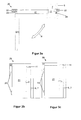
- FIG. 1 Fig. a shows a block diagram of a sensor device 10 according to an embodiment of the invention. It comprises an image sensor 11, ie a sensor which is set up to capture an image of a detection area 6, 7 currently monitored by it.
- the image sensor 11 is coupled to a controller 12 via a communication link 3.
- the controller 12 is additionally coupled to one or more position sensors 1 of the wing system not shown here.
- the here a position sensor 1 is an example of a bus connection 2 position data of one or more wings of the wing system to the controller 12 on. Positions may be, for example, a full opening or closed of the wing (plant).
- the image sensor 11 is capable of detecting, in a power saving mode, the detection area 7 exclusively formed by the broken line. Ie.
- the coverage area enclosed by this line is not or only rudimentarily recorded.
- the image sensor 11 when the image sensor 11 is switched to an active mode, it detects a detection area 7 which is smaller than or equal to the detection area enclosed by the line 7.
- the sensor 11 is further coupled via an associated data / communication link 4 with an image processing device 13, which processes the image data captured by the sensor 11 and optionally stores it internally or externally.
- the image processing device 13 is also via a data / communication connection 5 coupled to the controller 12 so that they can cause further action due to the image data evaluation. For example, the image processing device 13 performs only preprocessing of the image data of the sensor 11, whereas the controller 12 performs final checks.
- FIG. 2a shows an example of a variant of the image sensor 11 in a sleep mode.
- the sensor 11 includes, by way of example, lighting elements 15 in order to be able to detect the respective detection area to be monitored even under unfavorable external conditions.
- the radiation sensitivity of the sensor elements 14 may include thermal radiation, light radiation, radar radiation and the like.
- the alternative shown is in the energy-saving mode or, in a darker environment in the active mode, only every second lighting element 15'1 activated; the other lighting elements 15 are deactivated.
- the sensor elements 14 only those located on the outer edge are activated by way of example. The others are inactive. In the active mode, however, all sensor elements 14, except those on the outer edge, activated.
- sensor elements 14 ' At the in Figure 2c shown operating position are sensor elements 14 ', of which only three are provided with reference numerals, blackened. This means that these sensor elements 14 'are either inactive and thus no pixels in the image result, or are marked so that their pixels are ignored. This is used to hide certain detection ranges of the sensor elements 14 'belonging to the, later explained in more detail detection range 6, 7 of the sensor 11. Thus, in the example shown, for example, also discussed in more detail later, rotated wings 21 are hidden.
- the switching on and off of the lighting elements 15 and the sensor elements 14 takes place with the aid of the controller 12.
- the controller 12 may be part of the sensor 11 or may be coupled thereto.
- the first case lends itself to wing systems 20 without control, for example, for manual door systems on.
- the second case offers in wing systems 20 with an existing control for a drive, a lock or the like, the possibility to use this also for driving the sensor 11.
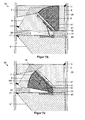
- FIG. 3a shows a single-winged rotary wing system 20, the wing 21 is hinged here left by means of angling 23. On the right, the wing 21 is in the closed position on a wing enclosure 22, for example in the form of a door frame. The wing 21 is shown by a dashed line in the fully open position. The directions of movement R of the wing 21 are indicated by a double arrow.
- the aforementioned sensor 11 is preferably mounted in a stationary manner on the upper edge of the wing 21, that is to say pointing in the direction of the observer.
- the sensor region 7, that is to say the detection region to be monitored in the energy saving mode, is here in cross section as an edge line a rectangle is formed and surrounds the main closing edge 24 of the wing 21 at such a distance that on the one hand is reliably detected when an object enters the sensor area 7, and on the other time switching the sensor 11 in the active mode is certainly possible.
- the detection areas to be monitored 6, 7 of the sensor 11 are formed frustoconical.
- the sensor 21 detects by way of example a region which is elliptical in cross section about the main closing edge 24.
- the fastening of the sensor 11 on the wing 21 has the advantage that the detection range to be monitored with the wing 21 "mitwandert". This makes it very easy to hide the wing 21 with respect to the sensory detection or deposit in an image memory such that the wing 21 is ignored in sensory detection, so it is not classified as a safety-relevant object.
- the sensor 11 also detects sensing areas of the wing enclosure 22 when the main closure edge 24 is close enough to the wing enclosure 22.
- the image processing device 13 is provided with a logic which is able to design the blade edge 22 as a non-safety-relevant object to recognize.
- the image processing device 13 now compares the image points detected by the sensor 11 and preferably compares them in conjunction with the current opening angle of the blade 21.
- the opening angle can be done, for example, by means of an incremental encoder, whose slotted disc rotates with the wing 21.
- the image processing logic then rotates the detected image according to the opening angle to a position corresponding to the vane 21 at a predetermined opening position, and adjusts whether or not the thus modified image matches the stored image data. This makes it possible to reliably distinguish the wing edging 22 from other objects.
- the following variant is also conceivable: If the sensor 11 captures image data in the first-mentioned case of the vanes 21 and in the second-mentioned case of the wing surround 22, the system automatically switches to the active mode of the sensor 11.
- the background is that the main closing edge 24 of the wing 21 in both cases is very close to the wing enclosure 22. In this situation, increased sensory sensitivity is required because there may be little time available for a corresponding safety response of the wing system 20.
- This arrangement is not only suitable for securing the main closing edge 24 with regard to pinching.
- a person is at risk of running against the main closing edge 24, it is possible by means of the sensor 11 to detect this. If it is an automated, so provided with a closer or drive wing 21, it is possible to cancel a determination of the wing 21, so that the shutter or drive is capable of the wing 21 in the closed position and thus the main closing edge 24 from the object to move away.
- this procedure can be refined to the effect that additionally the direction of movement of the object is determined. It comes from the left in FIG. 3b on the wing 21, the wing 21 from the drive closed. Conversely, if it comes from the right to the wing 21, the drive is preferably instructed to open the wing 21.
- each sensor 11 can be used. Are the arrangements according to Figure 3b and Figure 3c Combined, the safety of the wing system 20 increases dramatically. Since each sensor 11 is preferably operated independently, it can happen that one sensor 11 detects a safety-relevant object and the other does not.
- FIG. 4a shows another modification of the wing system 20.
- the wing enclosure 22 is formed by a wall 28, which also includes a corridor in which the wing system 20 with respect to its passageway extending vertically in FIG. 4a is trained.
- the wing 21 is hung on the right hinges 23 and pivots up in FIG. 4a ,
- the detection area 6 for the power saving mode of the upper sensor 11 here is formed by means of a rectangular peripheral line, whereas the detection area 7 for the active mode of the sensor 11 comprises the rectangle as an area.
- FIG. 4b shows the course of the detection areas 6, 7 according to certain opening positions of the wing 21. It can be seen that the detection areas 6, 7 from a certain opening angle of the wing 21 paint the wall 28. If the wall 28 does not go to the ceiling, not shown, it may be that the sensor 11 "looks over the wall", which should be avoided. In particular, the wall 28 to be moved virtually to the sensor 11 does not constitute an obstacle and thus does not pose a safety risk. In order to avoid unnecessary activation of the sensor 11, at least one image of the wall 28 is stored in advance and later acquired by the respective image of the sensor 11 Detected area 7 deducted. As a result, the sensor 11 does not have to be activated despite the wall 28. This version has another advantage.
- the sensor 11 can simultaneously serve to determine the fully open state of the wing 21, for example in the context of a learning run. The system is simply entered a minimum distance, and the sensor 11 can be used to determine up to what angle the wing 21 can be opened.
- the detection regions 6, 7 can be cut program-technically in the aforementioned learning run. As soon as the wall enters the image detection area when the wing 21 is opened, it is determined which sensor elements 14 of the sensor 11 detect a detection area which lies in or behind the wall 28 from the perspective of the wing 21. Ie. starting from a predetermined opening angle of the wing 21, the detection areas 6, 7 become smaller.
- the individual detection areas 6, 7 are combined to form a respective, entire detection area 7 ', 7', as in FIG Figure 4c shown.
- FIG. 5a shows a trained as a two-leaf sliding door system wing system 20. Their wings 21 are closed, and in the passage direction, ie vertically in FIG. 5a , A sensor 11 is arranged in front of and behind the wings 21. The wings 21 close a passage formed by the wing enclosure. The inside white, rounded squares represent by the sensors 11 each detectable as a pixel detection areas.
- FIG. 5b shows the wing system 20 of FIG. 5a with detection areas 6, 7 for the upper and a detection area 7 for the lower sensor 11.
- the detection areas 7 are characterized by a respective black, thick border line.
- the detection area 7 of the upper sensor 11 when the wings 21 are opened, ie when they are moved apart, is indicated by means of cross-hatched squares.
- This detection area 7 covers, in particular, the detection area which is passed by the respective secondary closing edge 25 of the associated wing 21 along the wing enclosure 22. It is therefore a Crowschrichkantenabêt the wings 21.
- the detection areas 7 are preferably changed in the case of both sensors 11.
- the detection areas 7 cover the entire passage of the wing system 20 from. This allows the seamless monitoring of the passage and thus in particular the avoidance of entrapment between the main closing edges 24 of the wing 21. It is therefore a Haupt Sch Strukturkanten temperament.
- This embodiment reflects a particular advantage, namely that of the adaptable to the opening state of a wing system 20 detection areas 6, 7th
- FIG. 6 shows one too FIG. 5 extended sliding door system 20.
- the sensors 11 comprise two energy-saving modes. If the wing system 20 is closed, both sensors are in a first energy-saving mode, in which only the outer edge of an in FIG. 6a visible rectangle is detected. Many small detection circuits result in the detection area 7 for this energy-saving mode.
- an object O passes through the detection area 7 here in the form of a person, as in FIG. 6b shown, this is detected by the sensor 11, and this is switched to a second energy-saving mode.
- this second energy-saving mode as in FIG. 6c shown, detection areas 7 'of the sensors 11 are activated, which are enclosed by the detection area 6 and, seen from above, are hexagonal in cross-section and taper in the direction of wing system 20 each.
- the direction of movement R of the object O on the basis of successively detected images here of the upper detection range 6 'is determined and checked whether an inspection of the wing system 20 is to be expected or not. This is done by checking whether the direction of movement R points in the direction of passage of the wing system 20.
- the opening of the wings 21 are initiated and the sensors 11 are set in the active mode.
- the sensors now detect the passage area of the wing system 20 in the form of the detection areas 7.
- the detection area 7 of the lower sensor 11 is used to determine whether, and if so, when the object O has moved so far from the wing system 20 that it can be safely closed.
- the wing 21 could continue to move if the prediction indicates that a collision is excluded, even though the object in question touches the security area.
- An advantage of such a solution is that a higher security against collisions is achieved, combined with increased ease of use. Also, the total opening time of the wing system can be reduced.
- FIG. 7 again shows a rotary vane system 20, but with three, with respect to the wing system 20 arranged sensors 11, 11 ', 11 ". Their detection areas 6, 6', 6" are represented by different hatching and border lines distinguishable from each other.
- a slide rail 41 is mounted, in which one end of a sliding arm 42 is received guided in a known manner.
- the other end the sliding arm 42 is also rotatably mounted in a known manner to a rotary vane drive 40, which in turn is stationary with respect to the wing system 20, preferably crash mounted.
- the rotary wing 21 closes in the closed position a passage formed by a wing enclosure 22 of a passage which is formed by means of a wall 28.
- the double arrow represents the pivot directions R of the rotary wing 21st
- the rotary wing 21 continues to open, as in FIG. 7b represented by the arrow R, only the sensor 11 can monitor the detection area to the right of the wing 21 by means of its detection area 6. If an object enters this part of the detection area 6, only the sensor 11 is put in the active mode, as a result of which the darker hatched detection area 7 is activated.
- the detection area 7 is the detection area in which the wing 21 with the wall 28 could pinch an object.
- FIG. 8 shows another rotary wing system 20.
- a sensor 11 is provided here by way of example, the detection area 7 is shown. As can be seen, this encloses the wing 21, seen in cross-section, including its main closing edge 24 and side closing edge 25.
- the rotary vane system 20 is exemplarily designed purely as an exit door and not as an entrance door, the exit direction downwards in FIG. 8 has. Ie. no through traffic is provided in the other passage direction.
- a drive 40 is provided to open and close the rotary wing 21.
- the detection areas 6, 7 of the non-illustrated sensor 11 are down in FIG. 8 Preferably designed so that they include with respect to the wing system 20 from above, ie in the direction of leaf level, the entire pivoting or rotating range of the rotary wing 21. Up in FIG. 8 Only a relatively narrow detection range is required, since only then there is a danger when the rotary wing 21 is closed. On the other hand, when opening, at least a minimal part of the swivel range must be free, so that the rotary wing 21 can be opened so far that objects can pass the wing system 20.
- a detection area 7 is provided for the sensor 11, which preferably covers the entire pivoting area of the wing 21.
- a minimum passage width that is necessary and thus a minimum required rotary vane opening angle are determined.
- the lower detection area 7 only checked for the presence of any obstacles within the minimum slewing range resulting from the previous values. This increases the safety of the wing system 20 and reduces the likelihood of unnecessary stoppage of the drive 40 and thus the wing system 20th
- FIG. 9 shows a pendulum wing system 20, so a system 20, the wings 21 pivot when opening from a closed position out in two directions or rotate, as indicated by the double arrow.
- the left and the right sensor 11, 11 serve to secure the secondary closing edge 25 and the main closing edge 24 and are preferably formed according to the above explanations.
- the middle sensor 11 is advantageously designed so that it can be used for both pivoting ranges of the wing 21.
- Its detection area 7 is designed such that it covers the walls enclosing the wing 21 or a frame enclosing the wing 21, at least in the edge areas facing the wing 21, and is curved in an exemplary manner starting from these. If an object arrives here in the lower detection area 7, the sensor 11 is first switched so that the part 7a of the detection area 7 of the sensor 11 is activated, which is located on the side of the wing 21 facing the object.
- a second partial detection area 7b is activated on the side of the wing 21 facing away from the detected object, which has the same role as in the previously described rotary vane installation. If no safety-relevant object is detected in the part detection area 7b, the pendulum wing 21 can move into the Part detection range 7b into, for example, by means of a drive 40 are pivoted.
- the part detection areas 7a, 7b are activated simultaneously.
- FIG. 10 shows a double-winged vane system 20 having a trained as a moving leaf 26 first wing 21 and a fixed wing 27 formed as second wing 21. D. h. the active leaf 26 pictured here on the left overturns the inactive leaf 27 in the closed position.
- the senor 11 according to the invention can be used to implement a closing sequence control, which is known to ensure that the active leaf 26 can only be fully closed when the inactive leaf 27 is already closed, and otherwise ensures that the active leaf 26 only up to a certain Angle can be closed, in which the inactive leaf 27 safely on the moving leaf 26 moves over and can be closed.
- a closing sequence control which is known to ensure that the active leaf 26 can only be fully closed when the inactive leaf 27 is already closed, and otherwise ensures that the active leaf 26 only up to a certain Angle can be closed, in which the inactive leaf 27 safely on the moving leaf 26 moves over and can be closed.
- the sensor 11 With regard to the sensor 11, in turn, only its detection areas 6, 7 are shown. If the wing system 20 is closed, as shown, the sensor 11 is preferably in a sleep mode in which it is advantageously completely switched off, ie has no or only a very low energy requirement.
- the detection areas 6, 7 of the sensor 11 are located, for example, in a detection area of the wing system 20, in which the main closing edges 24 of the wings 26, 27 could come very close and collide with each other. If the active leaf 26, or the passive leaf 27, are opened, the sensor 11 is placed in the energy-saving mode.
- the wings 26, 27 are in the detection area 7 and no other object enters the detection area 7, nothing happens; the wing or wings 26, 27 will be opened. If the wing 26 leaves the detection area 7, at the latest at this time an associated control is signaled that the inactive leaf 27 can be released.
- the sensor 11 is put into the active mode so that its detection area 7 is activated, which here corresponds to the area enclosed by the detection area 7.
- the active mode it is now determined whether it is to be expected that the object could get into the dangerous detection range between the main closing edges 24 or not. If this is the case, the wings 26, 27, if both are open, can be detected or moved in the open position, so that the possible risk is eliminated.
- the sensor 11 is switched to the energy-saving mode. In addition, the wing or wings 26, 27 can be released again.
- the active leaf 26 can preferably be closed first. If it enters the detection area 7 of the sensor 11, this is put back into the active mode. In this mode now recognizes the image processing device 13, not shown here, that only the active leaf 26 is in the detection area 7. Then, the image processing device 13 checks whether the inactive leaf 27 is closed so far that the active leaf can close safely. If the image processing device 13 can not detect the passive leaf 27 at all, that is, if it is opened too far, the active leaf 26 is blocked in the closing direction. If the inactive leaf 27 is detected, however, the image processing device 13 either determines whether the inactive leaf 27 is closed or not.
- the opening angle of the inactive leaf 27 for example by means of an incremental encoder operatively connected to the inactive leaf 27, and then tests it against a predetermined, maximum opening angle at which the active leaf 26 can be closed and urges the passive leaf 27 into sliding position.
- the processing of the positions of the wings 26, 27 takes place by means of a respective position sensor, for example in the form of one incremental encoder each.
- the senor 11 can also be used for lock control, be it in a multi-leaf rotary vane installation with in the same direction rotatable wings or a wing system in the passage direction successively arranged through wings.
- FIG. 11 A shows a designed as a single-leaf sliding door system wing system 20.
- Their sliding wing 21 is in the closed position and is driven to the left in the open position.
- the sliding wing 21 is, as seen in Begehungscardi, bordered on the right and left of two walls 28.
- the detection areas 6, 7 of the right-hand sensor 11 surround the main closing edge 24 and thus serve the main closing edge protection.
- the detection areas of the left-hand sensor 11 surround, by way of example, the entire path of movement of the wing 21 and are therefore suitable for obstacle detection in the detection area of the secondary closing edge 25. If the wing 21 is opened, it is preferably provided that the detection area 7 is successively reduced to the left.
- the associated sensor elements 14 of the sensor 11 are switched off successively from right to left, until in the fully open position of the wing 21 only the detection area is detected by the minor closing edge 25 around. If the wing 21 is opened again, the sensor elements 14 are switched on again depending on the opening position of the wing 21. Of course, this switching on and off also relates to the detection area 7 for the active mode of this sensor 11.
- a maximum opening width of the wing system 20 can be determined and compared with the minimum necessary opening width for the passing objects. If the minimum opening width is smaller than or equal to the determined maximum possible opening width, the control unit can be instructed to open the wing system 20 despite an obstacle in the path of movement of the wing 21 to an opening width which advantageously corresponds to the determined maximum possible opening width.
- FIG. 11b shows the application of sensors 11 in a double-wing sliding sash unit 20.
- the secondary closing edges 25 of the wings 21 are preferably as in the single-leaf sliding door system of FIG. 11 a secured.
- the main closing edges 24 of the wings 21, in turn, are secured here by means of a sensor 11, again represented by its detection areas 6, 7.
- these detection areas 6, 7 also "move" with the movements of the wings 21, 21. This has the advantage of being able to determine at any time how far the wings 21, 21 can be closed, without any danger to persons.
- FIG. 11c shows a formed as a telescopic sliding door system 20.
- the left wall 28 is formed as a station, in which the telescopic wings 21, 21 are retracted in the closed position.
- the left sensor 11 detects the rake edge region of the station and serves the Mauschrichkanteneêt both wings 21.
- the central sensor 11 detects the detection range preferably both between the Fineschdivkante 25 of the lower, outer wing 21 of the wing system 20 and the upper, inner wing 21 of the wing system 20th and between the main closing edge 24 of the outer wing 21 and the inner wing 21 of the wing system 20th
- both wings 21 move to the left, the lower at about twice the speed, as indicated by means of the double arrows of different lengths.
- the detection areas 6, 7 of the central sensor 11 remain in the center in the detection range of the minor closing edge 24 of the outer wing 21, to prevent this wing 21 an object on the left wall 28 or even between the wings 21 clamps. If, however, the wings 21 are closed again, the detection areas 6, 7 of the central sensor 11 are switched so that their centers are now in the detection range of the main closing edge 24 of the inner wing 21 and with their movement "mitwandern", again to prevent an object between the wings 21 is clamped.
- the right sensor 11 serves to protect the main closing edge 24 of the outer wing 21.
- this sensor 11 can be completely switched off, so are in a sleep mode, since at this time no danger from the main closing edge 24 of the outer wing 21 , If the outer wing 21 is closed, however, There is a risk of pinching between said main closing edge 24 and the right wall 28.
- the detection areas 6, 7 of the right sensor 11 are adjusted to surround the main closing edge 24 of the outer wing and extend to the facing edge of the right wall 28. This allows the detection of any obstacles in the path of movement of the outer wing 21.
- an object is in this path, can be determined by the image processing device 13 using the detection range 7 of the right sensor 11 in the active mode, a minimum opening width of the wing system and the wing system 20 to be closed by then. This has, for example, outside doors air conditioning advantages. If the wing system 20 despite object maximum closed, for example, less heat can escape. And yet the object in question can pass the wing system 20. In particular, disabled people can pass through the wing without hurry, without fear that the wing system 20 closes too fast.
- the still outstanding, left sensor 11 serves to secure the station in the right edge area, in which the wings 21 retract when closing.
- this sensor 11 may be completely turned off, so are in the aforementioned sleep mode, since at this time no danger emanates from the wings 21 in this retraction area.
- the wings 21 are opened, there is a risk of shearing objects in the detection area between the lower, horizontal wall section of the station and the secondary closing edge 24 of the inner wing 21 in this state. If such a danger is detected, an alarm is triggered, for example. Otherwise, the left sensor 11 is first operated in the power saving mode as in the previous embodiments, and its detection areas 6, 7 are in terms the wing system 20 arranged stationary.
- the middle sensor 11 can be put into sleep mode or remain active as a redundant safety device, ie be operated in energy-saving mode. Alternatively, the left sensor 11 is put into sleep mode.
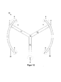
- FIG. 12 Two drum walls 30 define the passage of the revolving door system 20 in a known manner frontal ends of the wings 21 danger areas with regard to possible pinching or shearing. Therefore, these detection areas are preferably each provided with a sensor 11, again indicated by means of their detection areas 6, 7.
- the detection areas 6, 7 are identical in their outer contour, except that the detection area 7 is formed by the area surrounding the detection area 7.
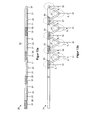
- FIG. 13 shows a trained as a folding door system wing system 20, once in closed position ( FIG. 13a ) and once in a partial open position ( FIG. 13b ).
- the individual folding wings 21 are pivotally connected to each other in a known manner via hinges 31. From the left in FIG. 13 seen each odd swivel joint 31 is arranged here via a respective associated carriage 33 in a guide rail 32 along a predetermined path movable. The rightmost pivot 31 is stationary with respect to the wing assembly 20. Therefore, this hinge 31 forms a kind of secondary closing edge 24 and the leftmost outermost hinge 31 forms a kind of main closing edge 24.
- sensors 11 are preferably arranged in the detection range of all hinges. In FIG. 13b are their detection areas 6, 7 indicated. This also provides the opportunity to determine how far the wing system 20 can be opened without risk of entrapment with the / n detected object / s. In the detection range of the right hinge 31, a risk of pinching could be similar to the detection range of the minor closing edge of a rotary wing. Therefore, a sensor 11 may be arranged here in order to realize a kind of Mausch Strukturkantensch.
- sensors 11 arranged at each swivel joint 31 may preferably be designed to detect these collision-sensitive detection regions and also to adapt the detection regions 6, 7 to the respective opening state of the wing system 20. This also offers the Possibility to determine how far the wing system 20 can be closed without collision with the detected object (s).
- the sensors 11, apart from the sensor 11 at the main closing edge 24, are switched to sleep mode.
- the right-hand sensor 11 is operated in the energy-saving mode and serves as the classic main closing edge protection.
- the above-described sensors 11 are preferably designed as so-called TOF cameras whose sensor elements 14 are based on light transit time measurement. Ie. the image of the respective sensor detection area 6, 7 is formed by light pulses directed by the illumination elements 15 being emitted into the detection area and, depending on the distance of the object hit by the light, this light to photoelectric sensor elements 14 of the sensor 11 is reflected. The sensor elements 14 detect the reflected light, and the sensor 11 determines how much time has elapsed. This is preferably done with the aid of a special microcontroller, which is the time between transmission and reception of the (reflected by an object) light pulse, measures or determined and thereby determines the distance of the sensor 11 to the object, assuming a constant speed of light.
- a special microcontroller which is the time between transmission and reception of the (reflected by an object) light pulse, measures or determined and thereby determines the distance of the sensor 11 to the object, assuming a constant speed of light.
- the image thus formed is thus less a representation of reality than an image of the transit time of the light from the illumination elements 15 to the relevant sensor elements 14.
- the advantage of such sensors is that by means of this light transit time measurement method, also called T ime O f F light ( abbreviated TOF) the distance from the sensor 11 to the respective object or to the sensor 11 facing surface of this object with high accuracy reliability and largely independent of the nature of this surface. Depending on the distance, the light striking the individual pixel of the sensor 11 or sensor element 14 experiences a delay.
- T ime O f F light abbreviated TOF
- the time duration or length t D of the light pulses determines the maximum distance range that the camera can cover.
- the illumination device 15 is provided or formed for this purpose with very short-switching bulbs such as special LEDs and / or with elaborate lasers to be controlled to generate these short pulses.
- the illumination elements 15 preferably emit light in the visible and / or invisible wavelength range.
- it may be provided in the energy saving mode that the in FIG. 2b shown activated lighting elements 15 emit light in the invisible wavelength range and emit in the active mode all activated lighting elements 15 light in the visible detection range.
- Suitable lighting devices 14 are laser light sources, in particular laser diodes or infrared light emitting diodes with scattering characteristics. It is advantageous in any case, the use of monochromatic light, ie a light with a constant wavelength or uniform frequency.
- photosensitive, electronic components are used as sensor elements 14.
- the sensor 11 comprises a line or matrix sensor with a plurality of sensor elements 14, for example in the form of a CCD sensor.
- a plurality of sensor elements 14 for example in the form of a CCD sensor.
- electronic components are used as sensor elements 14.
- an additional projection optics (lenses, mirror optics) in the optical path between the sensor elements 14 or the lighting elements and the detection area, an image of any object present in the detection area can thus be projected on the line or matrix sensor.
- differences between the light propagation times for different, preferably in each case directly adjacent sensor elements 14 of the sensor 11 are determined. This creates a relief-like image of the projected surface.
- two images are taken one after the other in a very rapid sequence at a certain time interval to the transmitted light pulse.
- the recordings are scheduled exactly like that first part of the light pulse from the temporally first recording and a second part of the same light pulse are detected by the temporally second recording. From the brightness ratio of the two images with respect to the received reflection light, the distance of the object from the sensor 11 is determined.
- the advantage is that no direct time measurement in the sense of a stopwatch is necessary.
- the light pulse is significantly shorter in time than the metering light transit time.
- a background suppression is also provided, which serves the purpose of hiding non-security objects, such as elements of the wing system or building parts such as a floor, balls and the like, in the images.
- one or more 3D reference image (s) of the respective objects to be hidden or of the entire detection area without security-relevant objects are stored in a memory.
- the reference images are taken as the basis for the respective current image or subtracted from it as a value at the corresponding pixel locations. What remains is likely an object in the sense of the application. Certain tolerances can be provided in the values.
- Several reference pictures improve the recognition accuracy.
- the reference image (s) is not only recorded once during a teaching-in phase, but continuously updated or read aloud.
- an algorithm ensures that in the continuous post-learning process objects that are only temporarily in the detection area 6, 7 are not taken into account.
- the advantage is the inclusion of small or slowly occurring changes to the wing system 20, thus at least reducing unnecessary disturbances and improving the robustness of the wing system 20 as a whole.
- a plurality of images similar to a film are stored.
- the reference image (s) corresponding to this opening position is / are used. This is sensible both in the case of a sensor 11 mounted on a door leaf, which detects a constantly changing image of, for example, the aforesaid floor during door movement, as well as a sensor 11 fixed in relation to the wing installation 20, through the detection area of which a wing 21 emotional.
- the image processing device 13 is preferably set up to rotate, displace, distort or even scale in addition to the selection of the reference images to be used in accordance with the respective opening position of the relevant wing.
- Rotating the reference image may be necessary, for example, in rotary vane systems in which either a rotary vane moves past the sensor or it moves with the vane along a partially elliptical or part-circular line over, for example, a floor.
- a shifting of the reference image may be necessary, for example, in sliding sash systems in which either a sliding sash moves past the sensor 11 along a straight line or moves with the sash 21 along the straight line over, for example, a floor. Distortion and / or scaling may be required when, for example, a wing (s) 21 or lintel approaches or moves away from the sensor 11 during wing movement.
- image data reduction methods are applicable, for example, according to the MPEG4 standard, in which image areas with similar information are generally combined into larger regions and stored only once, and so on with less Data can be written digitally.
- Film sequences in turn draw more or less only a fixed image.
- the recordings overlap to a large extent.
- Such images of a film sequence can be assembled into a single image by analyzing the overlapping image areas. At the same time further movement, position and speed of the wing 21 and the sensor 11 can be determined.
- Such a uniform image requires significantly less storage space than a mere movie sequence in which there are many redundant information in the image overlaps.
- the superimposition of these image areas by interpolation between the various images can result in improved image quality and possibly also a higher resolution than in a single image.
- the individual images can be compared with a reference image composed in this way in order to analyze deviations that can be interpreted as safety-relevant objects or obstacles, and at the same time the position of the respective wing, ie even without classical displacement sensors such as incremental encoder, Hall sensor and the like.
- intelligent image data monitoring and reconstruction is preferably provided or implemented in sensor 11. This is done by logical comparisons with the determined data immediately adjacent pixels or pixel areas in the image checked whether the pixel to be checked has a different characteristic. This can be recognized, for example, by means of a brightness that differs significantly from the neighboring pixels or even darkness of the relevant pixel. Thus, a kind of erroneous measurement is detected.
- the background is that objects such as a person are always represented in the image by multiple pixels. When such an object moves through detection areas 6, 7 of the sensor 11, the resulting movement history can be tracked logically.
- a preferably individual pixel, which provides information that is not suitable for this purpose, can be identified as defective because its value does not change, although it would have to. The same applies, for example, when observing a level floor or the like.
- the relevant sensor 11 is able to change its viewing direction, for example, preferably motor-driven by means of minimal movement along a rail or pivoting about an axis and thus to accommodate two slightly offset images of the detection area 6, 7.
- two of these staggered images are compared. If a sensor element 14 is faulty, the correspondingly determined pixel value in both images will be identical or very similar, although this pixel value would have to occur due to the offset at another pixel. As a result, pixel errors can be clearly recognized and thus faulty sensor elements 14 can be identified. The pixels recognized as defective are ignored in image processing, for example by blackening them.
- a warning message for example, be sent to the image processing device 13, for example, to display a corresponding warning display to a monitoring center or the like.
- This allows staff to assess whether the sensor in question 11 is to be replaced or not.
- the viewing direction change can be achieved by a mechanism that moves the sensor 11 slightly, a special optics, a movable mirror, an optical prism or the like.
- the aforementioned test procedure is preferably carried out at predetermined time intervals and / or positions of the wing system 20, advantageously when the sensor 11 in question is not needed and, for example, is in the aforementioned sleep mode.
- a type of pixel reconstruction is provided. This is done by logical comparisons of adjacent pixels or pixel areas of multiple images with each other and their interpolation and overlay. As a result, the missing information of one or more pixels can be reconstructed.
- the senor 11 As an activation sensor, for example for generating an opening pulse for the wing system 20, it can be designed as a 3D camera with relatively few pixels (for example 9 ⁇ 9). In order to realize a sufficiently large detection angle in front of the wing installation 20, the individual image spots respectively capture relatively large spatial areas, ie they are not focused too strongly.
- the sensor 11 wide-angle characteristic, which can be realized for example by means of suitable optical lenses or a correspondingly curved surface of the sensor elements 14.
- the communication links 2-5 may be implemented in any form, be it, for example, as a BUS, wirelessly, over multiple lines, or the like. There may be different standard bus protocols like For example, Ethernet, CAN or the like can be used.
- the data line can also be realized as a serial interface or as an inter-controller BUS.
- the images, ie their image data, can be partially or completely distributed in the sensor 11, ie distributed, and / or in an associated image processing device 13 or even the controller 12.
- the image processing device 13 may be housed or integrated in a controller 12 of a wing drive 40 or door management system.
- an (inner) detection area or part of a sensor field formed by the sensor elements 14 can be switched off, and only the remaining sensor elements 14 remain active and monitor or detect the associated detection area 7 ( ⁇ energy-saving mode).
- the detection area 7 is selected such that an object reaching into the detection area of the wing installation 20 must at least strip this detection area and thus be detected by the sensor 11 in each case. If this happens, the sensor elements 14 switched on or activated, which cover the associated detection area 7 sensor ( ⁇ active mode). This could result in that sensor elements 14 are switched off, which cover the detection area 7, but not the detection area 7 sensor.
- the lighting elements 15 belonging to the respective sensor elements are also switched off, for example in the form of IR diodes.
- the sensor 11 can be clocked down in the energy-saving mode, whereby the number of detected images per unit of time is reduced and thus the energy requirement of the sensor 11 is lowered (further).
- the clock rate of the sensor 11 is increased, for example, to be able to react quickly and more precisely in a near zone of the wing system 20 or its wings 21 than in the energy-saving mode. Since the lighting elements 15 do not emit continuous light but light pulses, the light transmission power can thereby be significantly reduced. The light transmission power is almost proportional to the frame rate. With a reduction of the frame rate, for example from 20 frames / s to 7 frames / s, 2/3 of the required light transmission energy can thus be saved.
- the transmission power (amplitude, brightness) of the lighting elements 15 and thus the strength of the emitted light pulses in the energy-saving mode of the sensor 11, for example, in phases in which the wings 20 do not move, can be reduced.
- the sensor 11 it is sufficient for the sensor 11 to roughly recognize the relevant object.
- the transmission power of the sensor 11 can also be reduced in other cases.
- adjust its transmission brightness or performance depending on the distance of the sensor 11 to an opposing objects of the wing system 20, so an object to be ignored in the image, adjust its transmission brightness or performance. The closer the sensor 11 is to this object, the lower the transmission power can be in active mode. So it uses only as much energy as absolutely necessary.
- Such adaptation may also be according to other criteria. It may depend on the real picture quality (contours, brightness). The higher the ambient brightness, the brighter the lighting elements must shine. The same can apply with regard to the contours in the captured image.
- the sensor 11 can be completely switched off or put into the above-described sleep mode in times of non-use or standstill of the wing system 20.
- Suitable applications may be times in which the wing system 20 is closed or any of its wings 21 is moved by a program state of the wing system 20 (program switch the wing system 20 and a drive 40 is exemplified in closed position or continuous open position). Ie. the sleep mode is taken when no action or event is to be expected regarding the wing system 20.
- the senor 11 is preferably electrically connected to the controller 12, for example a wing drive 40.
- the sensor 11 can be activated by the drive 40 at any time via a special wake-up signal (eg own (trigger) line or BUS).
- a special wake-up signal eg own (trigger) line or BUS.
- the senor 11 has its own activation sensor. This can be, for example, a motion detector or passive infrared sensor.
- the sensor 11 in the case of, for example, an opening sensor in phases in which their Fiügei 21 are not moved and / or closed, recognize only persons to activate the wing 21, locking and / or drive system. Since a moving person is expected to always be recognized by several pixels, the number of pixels detected for detection can be reduced in these phases.
- the image processing device 13 for example in the form of a microcontroller, it is also possible to evaluate or interpret the respectively acquired image with regard to predetermined criteria.
- it can be determined how many objects are in the detection area 6, 7 of the respective sensor 11 or move. This is mainly based on the shape and size of a detection event.
- light reflections and surface color of the objects to be detected do not affect the captured image, so that the recognition of individual persons or objects is possible without too complex image adjustments or interpretations, what the robustness of the sensor 11 and thus the so equipped wing system 20 benefits.
- the direction detection of objects can have meaningful influence on the activities of the wing system 20 in many ways. For example, transverse to the wing system 20 or parallel to their closed wings 21 moving or even from the wing system 20 (again) removing objects do not lead to the opening of the wing system 20. However, as soon as an object moves in the direction of wing system 20 or turns in this direction and falls below a predetermined minimum distance from the wing system 20, the wing system 20 is opened. Furthermore, the determination of the movement path can result in a multi-wing system 20 having only one Wing 21 opens or several wings 21 open. Their maximum opening width can also be adapted to the width of the stream of objects that the wing system 20 currently wishes to pass through. This is particularly favorable for exterior doors, as this heat losses can be minimized through the wing system, especially on cold days.
- the sensor 11 according to the invention can be used not only as an opening sensor but also as a closing sensor.
- the sensor 11 On the basis of the determination of the distance and the direction of movement of the object (s) by the image processing device 13 or the sensor 11 itself, it can further be determined with the aid of the above-mentioned procedure if the object (s) has completely passed the wing system 20, or Although it is still very close to the wing system, the wings 21 can already be safely closed (for the object (s)).
- This procedure is particularly well suited for sliding sash systems. This makes it possible, the wing system 20 independently or even to close without permanently set opening time. As a result, the total opening duration of the wing system 20 can be reduced and less hot or cold air can be exchanged.
- the wing system 20 can be operated in such a way that an optionally initiated closing movement of the wing 21 leads to a sudden stop of the wing 21 and, if necessary, to its reversing, if an object is within the range of movement of the relevant wing 21 stops or even changes its direction of movement in the direction of the wing system 20 to.
- a forwarding of information such as speed, position, number of objects in the respective detection area 6, 7 to a drive of the wing system 20.
- This information can be forwarded in the form of physical, ie electrical data via a bus line or the like to a drive control
- this information is evaluated by the respective sensor 11 itself, so that only the result of the evaluation, for example as a logical state or situation description in the form of a flag (eg person is in the security zone), must be forwarded to the drive control.
- the senor 11 generates a relief-like image of the respective detection area 6, 7 as a projection from one direction.
- a front and a back it is preferably provided to image a scene with two or more sensors 11 from different angles.
- the image processing device 13 for example in the form of a computer, it is possible to assemble the images captured by the sensors 11 into a 3D image of the different viewing angles and in this way to produce a complete 3D image with front and back of the relevant object.
- the wing system 20 which is embodied, for example, as a revolving door system, completely with front and rear sensors and to define a complete safety zone in front, behind and in the detection area of the passage of the wing system 20.
- this safety zone moves with the wing movements, whereby the adaptability and optimization of the wing system 20 are improved in terms of their operation.
- the sensors 11 do not have to be positioned with millimeter precision.
- the image processing device 13 can determine the sensor positions and assign corresponding detection regions 6, 7 to the sensors 11.
- each sensor 11 has a suitable firmware or software interface.
- the sensors 11 can be mounted at almost any angle to each other. Their viewpoints can be compared by spatial image data comparison be recalculated. This eliminates the usually necessary, complex input to location and geometry data of the sensors 11 and the wing system 20. This allows an enormously simple easy installation and commissioning of both the wing system 20 and the individual sensors eleventh
- an object such as a shopping cart could be distinguished from a person. This can be prevented, for example, that a certain wing system 20 is passed with shopping cart. It could also be determined if the shopping cart is full or empty. This could be useful, for example, at automatic cash registers. At airports, for example, it could automatically be detected whether a person has a piece of luggage or not. It could be recognized if children instead of adults pass through the respective coverage area 6, 7 etc.
- the application possibilities are very complex.
- the senor 11 is capable of capturing at least the detection area 7 in detail, including the three-dimensionality of objects located therein, and directly determining the distance to the respective surface point, the method of capturing the respective image is largely immune to interference and tampering. which significantly improves the robustness of the wing system 20.
- the method can, as stated above, equally for the activation and for securing door systems, in particular automated door systems (sliding, turn and revolving doors use).
- the detection areas 6, 7 can be defined as activation areas and / or as backup areas, depending on which reaction to the detection an object takes place. Ie. the function of the sensor 11 itself remains largely the same.
- the definition of the detection areas 6, 7 with regard to meaning, size and / or training is preferably carried out by software. In this way dynamic transitions or transition zones can be defined.
- the limits of these detection areas 6, 7 can be shifted and adjusted by the controller 12 as a function of the respective position of the sash. In this way, for example, a hedging area can be kept as small as possible and always as large as necessary. This leads to the fact that the respective sensor 11 also detects only what is absolutely necessary, as a result of which the operation of the wing extensions 20 is further optimized.
- the adjustment of the dynamic detection range 6, 7 can also be done depending on other factors or parameters.
- the security area can be increased if there is a crowding situation in the wing area.
- the securing area can also be increased if high speeds of the objects moving in the respective detection area 6, 7 are determined.
- a plurality of security and / or activation areas may preferably be defined with multiple security zones of different weighting or importance.
- At least one sensor 11 is constructed such that its illumination devices 15 and / or sensor elements 14 are preferably grouped again on the software side and assigned to different detection regions 6, 7.
- These different detection areas 6, 7 can of course have different meanings, for example as an activation or security area.
- One or more safety zone (s) may or may be automatically formed around the wing assembly 20 due to the sensory captured images.
- the wing assembly 20 is capable of self-observing itself with the help of the sensors 11, so to speak, and in the event of changes (one of the sensors 11 has changed, the wing opening angle has changed continuously, ). n be readjusted continuously. Since the wing system 20 can be observed in each wing trip, in this approach not belonging to the wing system 20 objects that are only temporarily in the respective detection area 6, 7, are excluded. Separate settings, programming or parameterizations from the outside by a fitter are no longer required or can be determined by means of the sensor (s) 11. This not only simplifies the installation but also increases safety, as a misadjustment (eg too small a safety zone) can be ruled out.
- the sensor 11 preferably has a test and feedback contact or connection, which is coupled to the controller 12, for example, as part of a wing drive 40.
- the controller 12 After a test request from the controller 12, for example with a switching pulse in predefined, the controller 12 waits for a response. If this remains off, it is evaluated by the controller 12 as a failure of the sensor 11, and the controller switches the wing system 20 in a safe mode.
- each sensor 11 is implemented with a feedback input in the form of, for example, a discrete single input contact.
- a safety inquiry can be carried out by the controller 12 or image processing device 13 via this bus data line.
- a request is first sent to the sensor 11, which then responds in a predefined way with a logical response, which in turn by the requesting device, so the controller 12 and the image processing device 13, is checked.
- the security can be further increased if the response of the sensor 11 takes place only through some computing steps that are integrated in a program implemented in the sensor 11. This also allows the correct operation of the sensor microcontroller and its firmware can be monitored.
- sensors 11 also known as so-called sensor strips
- sensors 11 installed on the blade and moving along are a particularly effective solution.
- this is more difficult insofar as the fixed objects in space move relative to the sensor 11, and therefore are difficult to hide.
- a solution according to the invention for a co-moving sensor to distinguish fixed objects, reflecting surfaces or ground irregularities from persons and critical objects is a recording of sensor signals as a reference in a door drive without obstacle and a comparison of these reference signals with the signals of later door trips.
- the reference signal can be in the form of a film, that is, consist of many consecutively created individual images. These individual images are assigned to the respective position (usually angular position) of the wing system 20 or wing 21 and can be compared later in the different positions of the wings 21 with the current images.
- the individual images can be combined to form a complete image. This exploits the fact that the individual images overlap to a large extent. Using this overlap, an overall image can be created by moving, rotating and overlaying. The quality of this overall image can exceed the quality of the individual images because the redundant information can be assembled to higher quality information through evaluation and overlay algorithms, averaging and interpolation. Even the resolution can be increased.
- shots sometimes with different exposure settings
- the method is used for difficult light situations: Several blurred and noisy images with overexposed or too dark zones result in a sharper, less noise and balanced in Kotrast image.
- the current image and reference in the comparative Microcontroller for example, the image processing device 13, the current position or angular position of the wing system made known. This information can be determined or transmitted in different ways:
- the wing opening information may be transmitted from the controller 12 to the sensor 11.
- the angular position is via a data interface (analog signal, digital signal, bus signal) which can be designed as a data line, as a radio interface or as an optical interface.
- the opening position can be generally determined by the controller 12 by recalculation of the vane, possibly drive and linkage geometry from the position signals in the drive (eg incremental encoder on the motor or gear axis) or on the wing system 20.
- both position and opening or angular position of the associated blade 21 can be determined independently. In this case, it is not absolutely necessary to determine the actual absolute position of the wing 21 in the room. It is sufficient to generate an analog or digital path signal in which there is a fixed association between the path signal and the actual absolute position of the blade 21.
- the position signal This is used to assign the recorded reference images or certain sections of one or more reference images to the currently acquired image in order to be able to compare it with the reference image.
- the position signal generated by the sensor 11 is transmitted with the image data to this evaluation unit.
- the advantage of a position determination integrated in the sensor 11 is that neither external positional data need be transmitted to the sensor 11 nor determined. This is on the one hand a saving, and on the other hand it is achieved that the sensor 11 is a closed, module-like element and can be used more flexibly at and independently of the respective wing systems 20.
- a coordination of this data transmission between sensor 11 and evaluation unit would be necessary at least as regards the physical interface, the data format, the required quality of the position signal, the repetition accuracy, the data rate and the resolution.
- the sensor 11 is still another problem solvable. Detection ranges of classical sensors are always in front of or behind the closed blades 21, as seen in the passage direction. As described above, the sensor 11 is capable of being arranged in front of or behind the wing assembly 20, as seen in the direction of loading. Whose Detection area 7 is then also in front of or behind the wing system 20. However, if the wing system 20 is opened, and if the sensor 11 is or is put into the active mode, its detection area 7 can pass through the wing passage, so that it partially projects in front of and partially behind the wing system 20 is located. As a result, it is possible for the sensor 11 without additional sensors to monitor whether the respectively detected object has passed the passage or not. If so, the wing assembly 20 is closed again and the sensor 11 is placed in the power or sleep mode.
- a volume model of just that wing system 20 can be formed and stored.
- the images formed possibly geometrically imaged, d. H. moved, rotated, distorted, mirrored and / or scaled volume model based and thus "out" of the respective image. This makes it possible in particular to predict possible collisions with objects.
- the sensor 11 can be mounted anywhere; its detection areas 6, 7 can be adjusted accordingly. It can also be provided with an automatic tracking device. Based on the volume model given above, it is now possible to check whether the sensor 11 has changed its position with respect to the wing system 20 or not. If so, the sensor 11 is moved until the detected image coincides positionally with the formed volume model. This eliminates any adjustment work on the sensor 11; this can be done automatically.
- the sensor 11 as an activation and / or safety sensor can be used in any type of wing systems, ie in particular with wing systems with and without via gelbetillard (window drive, door closer, door drive, wing lock), especially in automatic sliding door systems, swing doors, revolving doors and curved sliding doors.
- the sensor 11 may be coupled to other access control devices, such as a fingerprint sensor. Fingerprint and a previously captured by the sensor 11 as a solid model image of each person can be saved. If a person now places a fingerprint on the fingerprint sensor, the person's current image can be used to check whether the currently detected fingerprint is known and, if so, whether that fingerprint can be reconciled with the person's image. This makes it harder, if not impossible, to gain access to a copied fingerprint.
- prison doors for example, can be secured, for example, by having previously stored faces of guards as volume models. This allows the blocking of any passage for unauthorized persons, and independent biometrics.
- the above-described sensors 11 can be used, for example, for burglary monitoring.
- a person eg, burglar
- a random one different object eg, animal, pet, cat, passerby, etc.
- the sensor 11 is superior to any optical camera because it must interpret the image complexly and rely on environmental conditions such as lighting, colors, demarcation between the objects, and the like.
- the sensor 11 can communicate, for example, by means of a radio interface with the higher-level controller 12 or image processing device 13, a wing control system or another sensor 11, which considerably simplifies the installation of the wing system 20.
- the sensors 11 can be supplied with energy in particular due to the lower energy requirement over time by means of batteries and / or solar elements, wherein the solar modules are preferably provided to charge the batteries.
- sensors 11 may be provided for gesture control, that is, for controlling by means of movements of a person.
- gesture control that is, for controlling by means of movements of a person.
- successively evaluated images are additionally compared with each other or their pixel values are subtracted from each other and the resulting difference image is examined for differences.
- This type of operation could be used in particular for programming and possibly parameterizing, for example, a wing drive coupled to the sensor 11.
- Doors can be operated by means of gestures. This has advantages, for example, for persons with wheelchairs, no longer awkward to operate a switch but by way of example only have to perform a certain hand movement to open a door.
- a time division multiplex method in which a sensor 11 superordinate control instructs the sensors 11 to turn on their illumination devices only at predetermined time intervals, which are designed so that sensors 11 with overlapping detection areas 6, 7 never in pairs at the same time their lighting devices 15 have turned on.
- these sensors 11 operate with differently modulated illumination frequencies and their sensor elements 14 also react only to the light frequencies set in the own sensor 11.
- the advantage is that the light of one sensor 11 in the other sensor 11 is considered or demodulated only as a background component and thus a falsification of the image of the respective sensor 11 is largely excluded or completely excluded.
- the above-described optional optics of the sensor 11 serve primarily to collect the light reflected from the surroundings.
- An optical bandpass filter is set to the wavelength of the sensor's own lighting device 15. Thus, a large part of the disturbing background light is eliminated.
- the senor 11 has a resolution of 204 x 204 pixels.
- the above-described removal determination of detected objects takes place directly in the sensor 11.
- calibration values are also stored in the system, preferably in the sensor 11.
- the interface is used under other USB or Ethernet .
- one or more quick e closures or switches are attached, which only pass the electrical signal for a very specific period.
- a downstream memory element sums the signal.
- the sensor 11 operates with two switches and two memory elements 14.
- the switches are preferably driven with a pulse signal of the same duration as the light pulse, with control signals for the switches being shifted relative to one another by one pulse length. If the reflected light now arrives at an object point in the detection area 6, 7 with a delay, only part of the reflected light signal reaches the associated sensor element 14, the other part is collected in the other sensor element 14. Depending on the distance, therefore, the ratio of the light received by the sensor elements 14 changes.
- a sine modulation is used in which the requirements for the edge steepness of the illumination pulses are lower.
- a distance threshold is set and only those pixels are considered that provide distances below this threshold. Complicated algorithms for object recognition are eliminated. This makes the application of the sensors 11 extremely robust.
- the sensors 11 depict the complete scenery, each with a single shot.
- Frame rates reach up to 100 frames per second for real-time applications.
- the sensors 11 work with almost all diffuse reflective materials.
- the third dimension in the images also makes measuring tasks such as the determination of object sizes easy to accomplish. This is advantageous for wing systems with lift gates.
- sensors 11 By means of sensors 11 a minimum opening height of the respective wing can be determined and then an existing door drive to open the door leaf are instructed.
- an acoustic and / or optical warning display can be made in the meantime in order to prevent the passing object from passing as long as the minimum opening height has not been reached.
- the above-described energy saving mode can be configured in multiple stages. From stage to stage, sensor elements 11 and / or illumination devices 15 are switched on or off individually or in groups. As a result, various safety or activation levels of the wing system can be realized. For example, in a door system 20 in the so-called automatic mode (automatic opening and / or closing of the door system 20), if the wings are closed and door have not been used for a long time, the full pulse rate of the sensor 11 and / or the power of the lighting even more reduced and reduced to the edge area of the detection area 7.
- a particularly suitable application for a sleep mode of the sensor 11 is a lockable wing system 20. As long as the lock is active, the sensor 11 is unnecessary, and can be turned off.
- the position and velocity determination in a moving sensor 11 mounted on a wing 21 can be made by comparing two images taken in quick succession or brightness profiles of a surface.
- the displacement of the two consecutively recorded images caused by the movement of the sensor 11 is determined by an evaluation algorithm.
- the absolute position of sensor 11 and wing 21 can be calculated.
- the velocity of the wing 21 can also be determined from the position or displacement values.
- the shifts between each image are directly proportional to the velocity. With this method, no additional measuring method or additional measuring device is needed to determine the position and velocity of the sensor.
- On moving sensor 11 is also preferably a measuring device for position or wing opening position attached.
- a measuring device for position or wing opening position attached.
- Such a measuring device can by means of an optical camera or an optical scanner, an additional Sensor 11, which is directed to a fixed object, an additional laser rangefinder according to the light transit time measurement method, ultrasonic distance sensor, active infrared sensor according to the triangulation method, an angle or distance measurement to one or more fixed in space Transmission sources (eg, light, radio, ultra-sound transmission source) and one or more receivers in communication with the sensor 11 or the wing system or by observing the wing system with a fixed in space 3D camera done.
- an additional Sensor 11 which is directed to a fixed object
- an additional laser rangefinder according to the light transit time measurement method
- ultrasonic distance sensor e.g., ultrasonic distance sensor
- active infrared sensor e.g., triangulation method
- measuring devices in which at least one part is attached to a fixed element of the wing system, which therefore do not work without contact.
- These are, for example, incremental encoder, cable position indicator, inductive position indicator and the like.
- these measuring methods have the disadvantage of a complex assembly, easy manipulation, disturbing optics and poor integration.
- an additional laser sensor mounted on the sensor 11 is suitable for the light transit time measurement method.
- the light beam of this rangefinder can be directed to a fixed object, for example a wall, at sensor height, that is above the heads of persons and other objects, the distance from the sensor to the stationary object being able to be determined with millimeter precision in this method.
- the reflection point of the light beam moves along the object and the measured distance changes.
- the change in the distance is the same for each wing ride and thus comparable.
- the signal is only needed for the assignment between reference and sash position In this case, neither proportionality nor linearity of the distance change depending on the respective wing position is required. Only the reproducibility of the signal is important. So it is also possible if the light beam of the rangefinder leaves the originally targeted object by the movement of the wing and hits another stationary object. This may result in a removal jump, but this is not problematic.
- the following methods may be used individually or in any combination with one another:
- To determine the current wing position not only a single, currently measured distance value but also the course of several distance values are used by means of the sensor 11. By comparison with a reference curve of the distance values, an unambiguous assignment to a specific position of the wing 21 can take place.
- When evaluating and assigning the measured distance values it is also possible to take into account that due to the physical inertia of the wing, larger jumps in position or speed are excluded. Thus, due to, for example, a sudden missing change in distance to an obstacle on the wing 21 are closed.
- transmission source fixedly arranged in space
- a transmission source may be a radio transmitter, a light source (preferably infra-red light), a sound source (preferably ultrasound) or another source of radiation.
- a light source preferably infra-red light
- a sound source preferably ultrasound
- the distance, the change in distance, opening position or opening position change are determined or a measurement signal assigned to these variables is generated. For example, with two directionally oriented receivers oriented in different directions, an opening position change can be detected by comparison.
- the problem can be eliminated that the distance between sensor 11 and reflection point on an object in several position or opening or angular positions of the wing 21 has the same value.
- the method can also be used in the reverse manner.
- the one or more transmission sources on the wing 21 or the sensor 11, and the receiver are fixed in space.
- some transmit sources could be on the blade or sensor 11, and others are fixed in space.
- individual receivers could be on the blade, and others are again fixed in space.
- a sensor 11 For sliding sash systems, it is sufficient to integrate a sensor 11 within a drive profile of an associated sliding sash drive such that its detection area 6, 7 at least also the range of motion covers the sliding sash.
- a sensor 11 may be provided, in which the detection field also extends to the other door side when the door is open; ie detection cone of the sensor 11 extends through the open wing system.
- a control program can be enabled to realize the parameterization of the respective drive by means of such a hand gesture or gesture recognition.
- a hand gesture with three outlined fingers could mean "speed level 3".
- the drive for parameterization is preferably switched to a special parameterization mode, which is canceled again after the parameterization.
- the normal operation of the wing system 20 could be controlled by means of the sensor 11 with gestures. Typical functions for this are switching between automatic mode, continuous open position and closed position. Also, the wing system could open or close only at a certain hand sign. This could be achieved that a door does not open for unauthorized persons and is conceivable, for example, for security areas. Other applications would be utility rooms or kitchen spaces in hotels. While guests walk past such a furnished door without opening it, For trained personnel, the door would be open to show hands without a specific key.
- the senor recognizes a certain geometric feature on the clothing of the person concerned.
- An access control could also be implemented via this method, if it is ensured that persons who are not supposed to have access to it can not have the identification feature recorded by the 3D camera.
- Either one or more secret hand gestures or gestures are agreed or the system evaluates the specific biometric characteristics of persons. These may be, for example, certain body or facial proportions such as eye relief, eye-to-nose distance or the like.
- the 3D image captured by the sensor 11 can be overlaid with a 2D optical image.
- this is also recorded by means of the (infrared) light generated by the sensor 11.
- the 3D image allows objects to be clearly separated from the background and recognized as such.
- With the 2D optical image additional details can be added through contrasts.
- FIGS. 13-15 show in detail three different modes of operation for the sensor 11.
- a method for operating this wing system 20 is possible according to the invention, as in Figure 14a shown. It includes first Steps of starting (S11) and initializing (S12) of the wing system 20. Then, according to the invention, at least one first sensor 11 is set in the energy-saving mode (S13) and initially operated in this mode. Then, it is checked (S14) whether or not this sensor 11 is to be awakened. If it does not wake up (no branch after step S14), the method returns to step S14 according to the known polling mechanism. Otherwise (yes branch after step S14), the relevant sensor 11 continues to operate in the active mode (S15). This prevents that the relevant sensor 11 is constantly in full readiness and thus requires a relatively large amount of energy.
- the energy-saving mode allows the operation of this sensor 11, for example, as an activation sensor or as an image sensor with a coarser resolution, ie not all the individual sensors 14 and their associated lighting elements 15 are switched on.
- the energy saving mode according to FIG. 14b a first sub-step (S132) of checking whether or not the relevant wing of the wing 20 is moving. If not (no branch after step S132), then this wing is still, is returned to step S132. Otherwise (yes branch after step S132), it is checked in a subsequent substep (S133) whether or not there is an object in the detection area 6 currently to be monitored by the relevant sensor 11. If not (no branch after step S133), it returns to substep S132. If, on the other hand, an object is located in the detection area to be monitored (yes branch after step S133), the awakening of the relevant sensor is initiated (S134).
- the active mode includes according to FIG. 14c preferably a first sub-step (S152), in turn, of checking whether or not the relevant wing of the wing system 20 is moving. If not (no-branch after step S152), it jumps to a checking step S155. Otherwise (no branch after step S152), in a subsequent step (S153), an image of the detection area 7 of the wing assembly 20 to be currently monitored is detected by the aforementioned at least one first sensor 11 and then checked (S154) as to whether in the acquired image a security object is detected or not.
- Security-relevant objects are, for example, persons and animals.
- Non-safety-relevant objects can be, for example, game balls or the like.
- step S154 If there are no security-relevant objects (no-branch after step S154), a return is made to sub-step S152. Otherwise (yes branch after step S154), step S155 is skipped. In test step S155 it is checked whether for the currently detected, safety-relevant object of the wing system 20 is a danger or not, so for example there is a risk of trapping. If not (no branch after step S155), it returns to substep S152. Otherwise (yes branch after step S155), the wing system 20 performs such a predetermined safety reaction (S156) that the danger to the object is at least reduced. With regard to the aforementioned risk of pinching, this could result in an abrupt halting of the respective moving wing 21 or even in its reversing.
- S156 predetermined safety reaction
- step S157 it is checked whether the relevant wing of the wing system 20 is in a predetermined end position, ie fully open or closed position, or not. If this is the case (yes branch after step S157), there is no danger to the detected, safety-relevant object (more), and a jump is made to step S152. On the other hand, if the relevant wing is not in the end position (no branch after step S157), the program jumps to step S13.
- This method is particularly suitable for safety sensors, for example in the detection range of the closing edges. Stands the relevant wing 21 still, there is no risk of trapping, and the relevant sensor 11 is not required.
- the former method variant may be modified to additionally integrate the aforementioned sleep mode as in FIG. 15a displayed.
- the method according to the invention further steps S23, S24 of putting this sensor in the sleep mode and the subsequent check whether the wing system 20 is activated is or not, up. If it is not activated (no branch after step S24), then it is preferably at rest, jumping back to test step S24. Otherwise (yes branch after step S24), the step S25 of moving and operating this sensor in its power-saving mode is continued.
- sleep mode the sensor 11 is preferably completely switched off, as a result of which its energy requirement can be further reduced over time.
- the sleep mode is particularly useful when the wing system 20 is stationary and whose wings 21 is closed / are. In this case, there is no danger for objects even in the coverage area to be monitored.
- the method can be used in accordance with the above-described energy-saving mode in conjunction with the sleep mode that is integrated in the process FIG. 14b include.
- step S252 of the power-saving mode that the relevant wing is at rest
- step S256 of checking whether the wing system 20 is inactivated or not is skipped. If it is inactivated (yes branch after step S256), it jumps to step S252. Otherwise (yes branch after step S256) is returned to substep S23 of the power saving mode '.
- the method according to the invention preferably comprises the above-described active mode, as in FIG. 15c shown.
- the other step references S271-S277 are for distinction from the previous embodiment of this method but are identical in content. In that case, if it is determined in the test step S277 that the wing concerned of the wing assembly 20 is in the predetermined end position (yes branch after step S277), it jumps to step S23 of putting the respective sensor in the sleep mode. Otherwise (no branch after step S277), step S272 of checking whether the wing concerned of the wing assembly 20 makes a movement or not jumps back.
- the step S24 of checking according to the previous embodiment, whether or not the wing equipment 20 is activated is checked by a step S34 of checking whether the wing equipment 20 is closed and at the same time inactivated, replaced.
- This method is particularly suitable for the operation of the relevant sensor 11 both as an opening sensor and as a safety sensor.
- the function of the opening sensor is known to recognize this when approaching an object such as a person and then initiate the opening operation of the wing system 20.
- this sensor is in the inactivated, closed state of the wing system 20 in energy saving mode. Ie. the sensor 11, it is possible to respond to a closer object.
- step S353 the sensor 11 is switched to the active mode (S35, S36) in order to be able to determine whether the object is to be expected Wing system 20 wants to pass, or whether it only moves past the wing system 20 so that the wing system 20 can remain closed.
- the active mode preferably comprises first of all a sub-step S362 of checking whether the relevant wing of the wing system 20 is moving or not. If this is the case (yes branch after step S362), the method returns to step S33 of putting the at least one first sensor 11 into sleep mode. Otherwise (no branch after step S362), a first and a next image of the detection range of the wing system 20 to be monitored at the time by the at least one first sensor are detected in a staggered manner (S363, S364). Thereafter, it is checked whether or not the detected object is still in the detection range of the wing apparatus 20 to be monitored (S365). If not (no branch after step S365), it returns to step S33.
- a moving direction of the detected object is determined on the basis of at least two of the last detected images (S366). This can be done simply by determining where and to what extent the object has moved in the next image to temporally previously acquired image. Based on the determined direction of movement and the distance of the detected object from the wing system 20 is now checked (S367), whether a visit of the wing system 20 is expected by the detected object or not. If, for example, the distance of the object to the wing system 20 remains approximately the same, or does it become larger, the object is very unlikely to pass the wing system 20 so that any door drives do not have to come into action, which would result in a significantly higher energy requirement than the object pure sensor operation. If it is expected to pass (yes branch after step S367), the opening of the wing assembly 20 is initiated (S368) and preferably jumped back to step S33 in parallel. Otherwise (no branch after step S367), the process returns to step S33 only.
- the invention is not limited to the above embodiments.
- test steps S14, S132, S133, S154, S155, S157, S24, S26, S252, S253, S256, S272, S274, S275, S277, S34, S36, S353, S35, S362, S365 and S367 according to the polling mechanism can be replaced by trigger steps.
Landscapes
- Physics & Mathematics (AREA)
- General Physics & Mathematics (AREA)
- Engineering & Computer Science (AREA)
- Electromagnetism (AREA)
- Life Sciences & Earth Sciences (AREA)
- General Life Sciences & Earth Sciences (AREA)
- Geophysics (AREA)
- Computer Networks & Wireless Communication (AREA)
- Radar, Positioning & Navigation (AREA)
- Remote Sensing (AREA)
- Geophysics And Detection Of Objects (AREA)
- Solid State Image Pick-Up Elements (AREA)
Applications Claiming Priority (1)
| Application Number | Priority Date | Filing Date | Title |
|---|---|---|---|
| DE102010033818A DE102010033818A1 (de) | 2010-08-09 | 2010-08-09 | Sensor |
Publications (2)
| Publication Number | Publication Date |
|---|---|
| EP2418517A2 true EP2418517A2 (fr) | 2012-02-15 |
| EP2418517A3 EP2418517A3 (fr) | 2017-03-29 |
Family
ID=44653088
Family Applications (1)
| Application Number | Title | Priority Date | Filing Date |
|---|---|---|---|
| EP11006272.6A Withdrawn EP2418517A3 (fr) | 2010-08-09 | 2011-07-29 | Capteur optoélectronique |
Country Status (2)
| Country | Link |
|---|---|
| EP (1) | EP2418517A3 (fr) |
| DE (1) | DE102010033818A1 (fr) |
Cited By (24)
| Publication number | Priority date | Publication date | Assignee | Title |
|---|---|---|---|---|
| EP3002615A1 (fr) * | 2014-10-03 | 2016-04-06 | Omron Corporation | Capteur et système de sécurité |
| WO2019115558A1 (fr) * | 2017-12-12 | 2019-06-20 | Bircher Reglomat Ag | Système de capteur 3d avec optique de forme libre |
| WO2019115561A1 (fr) * | 2017-12-12 | 2019-06-20 | Bircher Reglomat Ag | Système de capteur pour la capture tridimensionnelle d'une scène au moyen de plusieurs accumulations de photons |
| WO2019115559A1 (fr) * | 2017-12-12 | 2019-06-20 | Bircher Reglomat Ag | Système de détection 3d muni d'un éclairage de scène fonction d'un angle solide |
| EP3526433A1 (fr) * | 2016-10-11 | 2019-08-21 | Bircher Reglomat AG | Commande de corps de fermeture fonction de la situation |
| EP3575534A1 (fr) * | 2018-05-29 | 2019-12-04 | GEZE GmbH | Dispositif de sécurisation sensorielle des mouvements de battant d'une porte tournante automatique |
| IT201800009584A1 (it) * | 2018-10-18 | 2020-04-18 | Michele Gulinelli | Cancello automatico ad ante battenti |
| EP3519861A4 (fr) * | 2016-10-03 | 2020-09-02 | Sensotech, Inc. | Système de détection basé sur le temps de vol (tof) pour une porte automatique |
| WO2020229190A1 (fr) * | 2019-05-10 | 2020-11-19 | Bircher Reglomat Ag | Identification d'un objet sur la base d'une reconnaissance d'une partie de l'objet et de données de description d'un objet de référence |
| WO2020229189A1 (fr) * | 2019-05-10 | 2020-11-19 | Bircher Reglomat Ag | Système de détection tof doté d'un dispositif d'éclairage comprenant un réseau de sources lumineuses individuelles |
| WO2020229186A1 (fr) * | 2019-05-10 | 2020-11-19 | Bircher Reglomat Ag | Système de détection 3d apte à fonctionner dans différents modes de fonctionnement en fonction d'un état de fonctionnement d'un corps de fermeture |
| EP3686864A4 (fr) * | 2017-09-22 | 2021-01-27 | Sony Corporation | Dispositif de traitement d'informations, appareil de déplacement autonome, procédé et programme |
| EP3969712A1 (fr) * | 2019-05-13 | 2022-03-23 | ASSA ABLOY Entrance Systems AB | Opérateur de porte oscillante pour déplacer un battant de porte oscillante dans un trajet d'oscillation entre une position ouverte et une position fermée, porte oscillante et pièce dotée d'une porte oscillante |
| CN114793909A (zh) * | 2022-04-02 | 2022-07-29 | 青岛顺佑兴工程科技有限公司 | 一种过道回转门 |
| EP4043682A1 (fr) * | 2021-02-12 | 2022-08-17 | dormakaba Deutschland GmbH | Procédé de fonctionnement d'une installation de porte |
| EP4043683A1 (fr) * | 2021-02-12 | 2022-08-17 | dormakaba Deutschland GmbH | Procédé de fonctionnement d'une installation de porte et installation de porte correspondante |
| JPWO2023058610A1 (fr) * | 2021-10-06 | 2023-04-13 | ||
| WO2023094340A1 (fr) * | 2021-11-23 | 2023-06-01 | Assa Abloy Entrance Systems Ab | Module détecteur destiné à être utilisé dans un système d'entrée |
| JP2024010371A (ja) * | 2022-07-12 | 2024-01-24 | ナブテスコ株式会社 | 自動ドア装置、自動ドア用センサ、動線識別装置、動線識別方法、動線識別プログラム |
| JP2024010370A (ja) * | 2022-07-12 | 2024-01-24 | ナブテスコ株式会社 | 自動ドア装置、自動ドア用センサ、動線識別装置、動線識別方法、動線識別プログラム |
| US12123247B2 (en) | 2019-03-08 | 2024-10-22 | Inventio Ag | Access control system comprising a sliding door and visualization of status information |
| WO2025162615A1 (fr) * | 2024-01-31 | 2025-08-07 | Assa Abloy Entrance Systems Ab | Économies d'énergie dans un opérateur de porte et système d'actionnement de porte |
| EP4675314A1 (fr) * | 2024-07-04 | 2026-01-07 | Leuze electronic GmbH + Co. KG | Agencement de capteurs |
| US12612818B1 (en) | 2019-03-08 | 2026-04-28 | Inventio Ag | Access control system with a sliding door that can be opened from the inside without contact |
Families Citing this family (11)
| Publication number | Priority date | Publication date | Assignee | Title |
|---|---|---|---|---|
| DE102013013778B4 (de) * | 2013-01-11 | 2017-10-26 | Novoferm Tormatic Gmbh | Tor mit einer Detektionseinrichtung sowie ein Verfahren zur Anwendung der Detektionseinrichtung bei einem Tor |
| DE102014101190A1 (de) | 2014-01-31 | 2015-08-06 | Huf Hülsbeck & Fürst Gmbh & Co. Kg | Montagemodul |
| DE102014221953A1 (de) * | 2014-10-28 | 2016-04-28 | Strassacker Project GmbH & Co. KG | Sicherheitsanordnung für Schwenktore, Torflügel sowie Schwenktor und Verfahren zum Absichern eines Torflügels eines Schwenktores |
| DE102017208716B3 (de) | 2017-05-23 | 2018-09-06 | Geze Gmbh | Verfahren und vorrichtung zur automatischen positionsbestimmung von sensoren |
| DE102017215329B4 (de) * | 2017-09-01 | 2024-10-10 | Pepperl+Fuchs Se | Türsensoreinrichtung |
| JP7043322B2 (ja) * | 2018-03-30 | 2022-03-29 | ナブテスコ株式会社 | 人または物体を検知するセンサ、自動ドアシステム、自動ドアおよび自動ドアの評価方法 |
| DE102018214215A1 (de) * | 2018-08-22 | 2020-02-27 | Geze Gmbh | Vorrichtung zur Überwachung von Türen, Fenstern oder dergleichen |
| DE102020103381A1 (de) | 2020-02-11 | 2021-08-12 | Connaught Electronics Ltd. | Einklemmschutz für ein Fahrzeug |
| DE102020203626B4 (de) | 2020-03-20 | 2024-03-07 | Geze Gmbh | Automatische Fenster- oder Türanlage |
| DE102020117345A1 (de) | 2020-07-01 | 2022-01-05 | Dormakaba Deutschland Gmbh | Karusselltür mit lichtsignalfunktion |
| DE102020117346A1 (de) | 2020-07-01 | 2022-01-05 | Dormakaba Deutschland Gmbh | Karusselltür mit lichtsignalfunktion |
Family Cites Families (4)
| Publication number | Priority date | Publication date | Assignee | Title |
|---|---|---|---|---|
| US6455839B1 (en) * | 2000-12-15 | 2002-09-24 | Prospects, Corp. | Obstacle detection sensor using synchronous detection |
| DE102006053002B4 (de) * | 2006-11-10 | 2009-05-14 | Leuze Lumiflex Gmbh + Co. Kg | Optischer Sensor |
| DE102007028117A1 (de) * | 2007-06-19 | 2008-12-24 | Pepperl + Fuchs Gmbh | Verfahren und optischer Sensor zum Nachweis von Objekten im Bereich einer sicherheitsmäßig zu überwachenden Einrichtung, Computerprogramm und Computerprogrammprodukt |
| DE102007036677A1 (de) * | 2007-08-03 | 2009-02-19 | Leuze Lumiflex Gmbh + Co. Kg | Sicherheitssensor |
-
2010
- 2010-08-09 DE DE102010033818A patent/DE102010033818A1/de not_active Withdrawn
-
2011
- 2011-07-29 EP EP11006272.6A patent/EP2418517A3/fr not_active Withdrawn
Non-Patent Citations (1)
| Title |
|---|
| None |
Cited By (32)
| Publication number | Priority date | Publication date | Assignee | Title |
|---|---|---|---|---|
| CN105487131A (zh) * | 2014-10-03 | 2016-04-13 | 欧姆龙株式会社 | 传感器及安全系统 |
| US9709695B2 (en) | 2014-10-03 | 2017-07-18 | Omron Corporation | Sensor apparatus and hazard sensing system |
| CN105487131B (zh) * | 2014-10-03 | 2018-04-10 | 欧姆龙株式会社 | 传感器及安全系统 |
| EP3002615A1 (fr) * | 2014-10-03 | 2016-04-06 | Omron Corporation | Capteur et système de sécurité |
| EP3519861A4 (fr) * | 2016-10-03 | 2020-09-02 | Sensotech, Inc. | Système de détection basé sur le temps de vol (tof) pour une porte automatique |
| EP3526433A1 (fr) * | 2016-10-11 | 2019-08-21 | Bircher Reglomat AG | Commande de corps de fermeture fonction de la situation |
| EP3686864A4 (fr) * | 2017-09-22 | 2021-01-27 | Sony Corporation | Dispositif de traitement d'informations, appareil de déplacement autonome, procédé et programme |
| WO2019115558A1 (fr) * | 2017-12-12 | 2019-06-20 | Bircher Reglomat Ag | Système de capteur 3d avec optique de forme libre |
| WO2019115561A1 (fr) * | 2017-12-12 | 2019-06-20 | Bircher Reglomat Ag | Système de capteur pour la capture tridimensionnelle d'une scène au moyen de plusieurs accumulations de photons |
| WO2019115559A1 (fr) * | 2017-12-12 | 2019-06-20 | Bircher Reglomat Ag | Système de détection 3d muni d'un éclairage de scène fonction d'un angle solide |
| EP3575534A1 (fr) * | 2018-05-29 | 2019-12-04 | GEZE GmbH | Dispositif de sécurisation sensorielle des mouvements de battant d'une porte tournante automatique |
| CN110541650A (zh) * | 2018-05-29 | 2019-12-06 | 盖慈有限公司 | 用于传感保护自动旋转门的翼扇运动的设备 |
| IT201800009584A1 (it) * | 2018-10-18 | 2020-04-18 | Michele Gulinelli | Cancello automatico ad ante battenti |
| US12123247B2 (en) | 2019-03-08 | 2024-10-22 | Inventio Ag | Access control system comprising a sliding door and visualization of status information |
| US12612818B1 (en) | 2019-03-08 | 2026-04-28 | Inventio Ag | Access control system with a sliding door that can be opened from the inside without contact |
| WO2020229190A1 (fr) * | 2019-05-10 | 2020-11-19 | Bircher Reglomat Ag | Identification d'un objet sur la base d'une reconnaissance d'une partie de l'objet et de données de description d'un objet de référence |
| WO2020229189A1 (fr) * | 2019-05-10 | 2020-11-19 | Bircher Reglomat Ag | Système de détection tof doté d'un dispositif d'éclairage comprenant un réseau de sources lumineuses individuelles |
| WO2020229186A1 (fr) * | 2019-05-10 | 2020-11-19 | Bircher Reglomat Ag | Système de détection 3d apte à fonctionner dans différents modes de fonctionnement en fonction d'un état de fonctionnement d'un corps de fermeture |
| EP3969712A1 (fr) * | 2019-05-13 | 2022-03-23 | ASSA ABLOY Entrance Systems AB | Opérateur de porte oscillante pour déplacer un battant de porte oscillante dans un trajet d'oscillation entre une position ouverte et une position fermée, porte oscillante et pièce dotée d'une porte oscillante |
| US11939809B2 (en) | 2021-02-12 | 2024-03-26 | Dormakaba Deutschland Gmbh | Method for operating a door system and door system for same |
| CN114922536A (zh) * | 2021-02-12 | 2022-08-19 | 多玛凯拔德国有限公司 | 用于运行门设施的方法和用于实施该方法的门设施 |
| EP4043683A1 (fr) * | 2021-02-12 | 2022-08-17 | dormakaba Deutschland GmbH | Procédé de fonctionnement d'une installation de porte et installation de porte correspondante |
| EP4043682A1 (fr) * | 2021-02-12 | 2022-08-17 | dormakaba Deutschland GmbH | Procédé de fonctionnement d'une installation de porte |
| JP7637258B2 (ja) | 2021-10-06 | 2025-02-27 | ナブテスコ株式会社 | 自動ドア、自動ドアの診断装置、自動ドアの診断方法、自動ドアの診断プログラム |
| WO2023058610A1 (fr) * | 2021-10-06 | 2023-04-13 | ナブテスコ株式会社 | Porte automatique, dispositif de diagnostic pour porte automatique, procédé de diagnostic pour porte automatique et programme de diagnostic pour porte automatique |
| JPWO2023058610A1 (fr) * | 2021-10-06 | 2023-04-13 | ||
| WO2023094340A1 (fr) * | 2021-11-23 | 2023-06-01 | Assa Abloy Entrance Systems Ab | Module détecteur destiné à être utilisé dans un système d'entrée |
| CN114793909A (zh) * | 2022-04-02 | 2022-07-29 | 青岛顺佑兴工程科技有限公司 | 一种过道回转门 |
| JP2024010371A (ja) * | 2022-07-12 | 2024-01-24 | ナブテスコ株式会社 | 自動ドア装置、自動ドア用センサ、動線識別装置、動線識別方法、動線識別プログラム |
| JP2024010370A (ja) * | 2022-07-12 | 2024-01-24 | ナブテスコ株式会社 | 自動ドア装置、自動ドア用センサ、動線識別装置、動線識別方法、動線識別プログラム |
| WO2025162615A1 (fr) * | 2024-01-31 | 2025-08-07 | Assa Abloy Entrance Systems Ab | Économies d'énergie dans un opérateur de porte et système d'actionnement de porte |
| EP4675314A1 (fr) * | 2024-07-04 | 2026-01-07 | Leuze electronic GmbH + Co. KG | Agencement de capteurs |
Also Published As
| Publication number | Publication date |
|---|---|
| EP2418517A3 (fr) | 2017-03-29 |
| DE102010033818A1 (de) | 2012-02-09 |
Similar Documents
| Publication | Publication Date | Title |
|---|---|---|
| DE102010033818A1 (de) | Sensor | |
| EP0853299B2 (fr) | Procédé et dispositif de commande d'un aménagement pour porte en réponse à la présence des personnes | |
| EP2648022B1 (fr) | Dispositif de surveillance et porte pivotante | |
| EP3526963A1 (fr) | Surveillance d'objet par enregistrement d'image infrarouge et éclairage par impulsion infrarouge | |
| DE19522760C2 (de) | Automatische Tür und Verfahren zum Betrieb einer automatischen Tür | |
| WO2004084556A1 (fr) | Surveillance au niveau d'un ascenseur au moyen d'un capteur 3d | |
| EP1345444A1 (fr) | Systeme de sureillance video en trois dimensions avec une source de rayonnements infrarouges | |
| DE102008044990A1 (de) | Verfahren und Vorrichtung zur Ansteuerung und/oder Überwachung eines motorisch angetriebenen Flügels während der Öffnungsphase | |
| DE102009034848A1 (de) | Optoelektronischer Sensor | |
| DE19653026B4 (de) | Vorrichtung zur Ansteuerung und/oder Absicherung eines motorisch angetriebenen Flügels einer Tür, eines Fensters oder dergleichen | |
| EP3526433A1 (fr) | Commande de corps de fermeture fonction de la situation | |
| EP4266269A1 (fr) | Procédé de commande d'une installation de porte | |
| EP3135846B1 (fr) | Groupe propulseur avec unité de capteur pour la régulation d'entraînement | |
| DE29912572U1 (de) | Vorrichtung zum Öffnen bzw. Schließen eines Tores | |
| EP4547014A1 (fr) | Système de contrôle d'accès complémentaire pour chatière à commande rfid et procédé de contrôle complémentaire d'accès par une chatière à commande rfid | |
| EP3526727A2 (fr) | Interaction de flux d'objet stéréométrique | |
| WO2020229186A1 (fr) | Système de détection 3d apte à fonctionner dans différents modes de fonctionnement en fonction d'un état de fonctionnement d'un corps de fermeture | |
| EP0852313B1 (fr) | Dispositif pour la commande et/ou pour sécuriser les panneaux de portes motorisés, fenêtres ou analogues | |
| EP1865755B1 (fr) | Dispositif destiné à la commande d'un éclairage avec détection de présence | |
| WO2023186693A1 (fr) | Procédé, produit de programme informatique, système d'aide au stationnement, et bâtiment | |
| EP4265873B1 (fr) | Procédé de commande d'une installation de porte | |
| EP4265874A1 (fr) | Procédé de commande de deux installations de porte espacées l'une de l'autre | |
| WO2015078612A1 (fr) | Procédé de vidéosurveillance | |
| DE102022107274B4 (de) | System und Verfahren für die Gestenerkennung und/oder Gestensteuerung | |
| EP3258297A1 (fr) | Système de grille lumineuse |
Legal Events
| Date | Code | Title | Description |
|---|---|---|---|
| AK | Designated contracting states |
Kind code of ref document: A2 Designated state(s): AL AT BE BG CH CY CZ DE DK EE ES FI FR GB GR HR HU IE IS IT LI LT LU LV MC MK MT NL NO PL PT RO RS SE SI SK SM TR |
|
| AX | Request for extension of the european patent |
Extension state: BA ME |
|
| PUAI | Public reference made under article 153(3) epc to a published international application that has entered the european phase |
Free format text: ORIGINAL CODE: 0009012 |
|
| RAP1 | Party data changed (applicant data changed or rights of an application transferred) |
Owner name: DORMA DEUTSCHLAND GMBH |
|
| PUAL | Search report despatched |
Free format text: ORIGINAL CODE: 0009013 |
|
| AK | Designated contracting states |
Kind code of ref document: A3 Designated state(s): AL AT BE BG CH CY CZ DE DK EE ES FI FR GB GR HR HU IE IS IT LI LT LU LV MC MK MT NL NO PL PT RO RS SE SI SK SM TR |
|
| AX | Request for extension of the european patent |
Extension state: BA ME |
|
| RIC1 | Information provided on ipc code assigned before grant |
Ipc: G01V 8/20 20060101AFI20170218BHEP |
|
| RAP1 | Party data changed (applicant data changed or rights of an application transferred) |
Owner name: DORMAKABA DEUTSCHLAND GMBH |
|
| STAA | Information on the status of an ep patent application or granted ep patent |
Free format text: STATUS: REQUEST FOR EXAMINATION WAS MADE |
|
| 17P | Request for examination filed |
Effective date: 20170929 |
|
| RBV | Designated contracting states (corrected) |
Designated state(s): AL AT BE BG CH CY CZ DE DK EE ES FI FR GB GR HR HU IE IS IT LI LT LU LV MC MK MT NL NO PL PT RO RS SE SI SK SM TR |
|
| STAA | Information on the status of an ep patent application or granted ep patent |
Free format text: STATUS: EXAMINATION IS IN PROGRESS |
|
| 17Q | First examination report despatched |
Effective date: 20180508 |
|
| STAA | Information on the status of an ep patent application or granted ep patent |
Free format text: STATUS: THE APPLICATION IS DEEMED TO BE WITHDRAWN |
|
| 18D | Application deemed to be withdrawn |
Effective date: 20180919 |