EP4043683A1 - Procédé de fonctionnement d'une installation de porte et installation de porte correspondante - Google Patents
Procédé de fonctionnement d'une installation de porte et installation de porte correspondante Download PDFInfo
- Publication number
- EP4043683A1 EP4043683A1 EP21156782.1A EP21156782A EP4043683A1 EP 4043683 A1 EP4043683 A1 EP 4043683A1 EP 21156782 A EP21156782 A EP 21156782A EP 4043683 A1 EP4043683 A1 EP 4043683A1
- Authority
- EP
- European Patent Office
- Prior art keywords
- person
- door
- opening
- door system
- door leaf
- Prior art date
- Legal status (The legal status is an assumption and is not a legal conclusion. Google has not performed a legal analysis and makes no representation as to the accuracy of the status listed.)
- Pending
Links
Images

Classifications
-
- E—FIXED CONSTRUCTIONS
- E05—LOCKS; KEYS; WINDOW OR DOOR FITTINGS; SAFES
- E05F—DEVICES FOR MOVING WINGS INTO OPEN OR CLOSED POSITION; CHECKS FOR WINGS; WING FITTINGS NOT OTHERWISE PROVIDED FOR, CONCERNED WITH THE FUNCTIONING OF THE WING
- E05F15/00—Power-operated mechanisms for wings
- E05F15/70—Power-operated mechanisms for wings with automatic actuation
- E05F15/73—Power-operated mechanisms for wings with automatic actuation responsive to movement or presence of persons or objects
-
- E—FIXED CONSTRUCTIONS
- E05—LOCKS; KEYS; WINDOW OR DOOR FITTINGS; SAFES
- E05F—DEVICES FOR MOVING WINGS INTO OPEN OR CLOSED POSITION; CHECKS FOR WINGS; WING FITTINGS NOT OTHERWISE PROVIDED FOR, CONCERNED WITH THE FUNCTIONING OF THE WING
- E05F15/00—Power-operated mechanisms for wings
- E05F15/60—Power-operated mechanisms for wings using electrical actuators
- E05F15/603—Power-operated mechanisms for wings using electrical actuators using rotary electromotors
- E05F15/611—Power-operated mechanisms for wings using electrical actuators using rotary electromotors for swinging wings
-
- E—FIXED CONSTRUCTIONS
- E05—LOCKS; KEYS; WINDOW OR DOOR FITTINGS; SAFES
- E05F—DEVICES FOR MOVING WINGS INTO OPEN OR CLOSED POSITION; CHECKS FOR WINGS; WING FITTINGS NOT OTHERWISE PROVIDED FOR, CONCERNED WITH THE FUNCTIONING OF THE WING
- E05F15/00—Power-operated mechanisms for wings
- E05F15/70—Power-operated mechanisms for wings with automatic actuation
- E05F15/73—Power-operated mechanisms for wings with automatic actuation responsive to movement or presence of persons or objects
- E05F2015/767—Power-operated mechanisms for wings with automatic actuation responsive to movement or presence of persons or objects using cameras
-
- E—FIXED CONSTRUCTIONS
- E05—LOCKS; KEYS; WINDOW OR DOOR FITTINGS; SAFES
- E05Y—INDEXING SCHEME ASSOCIATED WITH SUBCLASSES E05D AND E05F, RELATING TO CONSTRUCTION ELEMENTS, ELECTRIC CONTROL, POWER SUPPLY, POWER SIGNAL OR TRANSMISSION, USER INTERFACES, MOUNTING OR COUPLING, DETAILS, ACCESSORIES, AUXILIARY OPERATIONS NOT OTHERWISE PROVIDED FOR, APPLICATION THEREOF
- E05Y2400/00—Electronic control; Electrical power; Power supply; Power or signal transmission; User interfaces
- E05Y2400/10—Electronic control
- E05Y2400/36—Speed control, detection or monitoring
-
- E—FIXED CONSTRUCTIONS
- E05—LOCKS; KEYS; WINDOW OR DOOR FITTINGS; SAFES
- E05Y—INDEXING SCHEME ASSOCIATED WITH SUBCLASSES E05D AND E05F, RELATING TO CONSTRUCTION ELEMENTS, ELECTRIC CONTROL, POWER SUPPLY, POWER SIGNAL OR TRANSMISSION, USER INTERFACES, MOUNTING OR COUPLING, DETAILS, ACCESSORIES, AUXILIARY OPERATIONS NOT OTHERWISE PROVIDED FOR, APPLICATION THEREOF
- E05Y2400/00—Electronic control; Electrical power; Power supply; Power or signal transmission; User interfaces
- E05Y2400/10—Electronic control
- E05Y2400/40—Control units therefor
-
- E—FIXED CONSTRUCTIONS
- E05—LOCKS; KEYS; WINDOW OR DOOR FITTINGS; SAFES
- E05Y—INDEXING SCHEME ASSOCIATED WITH SUBCLASSES E05D AND E05F, RELATING TO CONSTRUCTION ELEMENTS, ELECTRIC CONTROL, POWER SUPPLY, POWER SIGNAL OR TRANSMISSION, USER INTERFACES, MOUNTING OR COUPLING, DETAILS, ACCESSORIES, AUXILIARY OPERATIONS NOT OTHERWISE PROVIDED FOR, APPLICATION THEREOF
- E05Y2400/00—Electronic control; Electrical power; Power supply; Power or signal transmission; User interfaces
- E05Y2400/10—Electronic control
- E05Y2400/44—Sensors not directly associated with the wing movement
-
- E—FIXED CONSTRUCTIONS
- E05—LOCKS; KEYS; WINDOW OR DOOR FITTINGS; SAFES
- E05Y—INDEXING SCHEME ASSOCIATED WITH SUBCLASSES E05D AND E05F, RELATING TO CONSTRUCTION ELEMENTS, ELECTRIC CONTROL, POWER SUPPLY, POWER SIGNAL OR TRANSMISSION, USER INTERFACES, MOUNTING OR COUPLING, DETAILS, ACCESSORIES, AUXILIARY OPERATIONS NOT OTHERWISE PROVIDED FOR, APPLICATION THEREOF
- E05Y2400/00—Electronic control; Electrical power; Power supply; Power or signal transmission; User interfaces
- E05Y2400/10—Electronic control
- E05Y2400/50—Fault detection
-
- E—FIXED CONSTRUCTIONS
- E05—LOCKS; KEYS; WINDOW OR DOOR FITTINGS; SAFES
- E05Y—INDEXING SCHEME ASSOCIATED WITH SUBCLASSES E05D AND E05F, RELATING TO CONSTRUCTION ELEMENTS, ELECTRIC CONTROL, POWER SUPPLY, POWER SIGNAL OR TRANSMISSION, USER INTERFACES, MOUNTING OR COUPLING, DETAILS, ACCESSORIES, AUXILIARY OPERATIONS NOT OTHERWISE PROVIDED FOR, APPLICATION THEREOF
- E05Y2900/00—Application of doors, windows, wings or fittings thereof
- E05Y2900/10—Application of doors, windows, wings or fittings thereof for buildings or parts thereof
- E05Y2900/13—Type of wing
- E05Y2900/132—Doors
Definitions
- the invention relates to a method for operating a door system, the door system having at least one door leaf, and a sensor unit being set up and connected to a control unit of the door system, with the sensor unit, in particular designed as a radar sensor or as a camera, being used to detect a person approaching the door system is detected.
- the invention also relates to a door system with a control unit for carrying out the method.
- the EP 3 613 933 A1 a method for operating an automatic door system that has a door operator that is connected to a door leaf. It is stated here that radar motion detectors are used to control the door movement for automatic sliding doors. Radar sensors for detecting monitored areas are not common for swing doors, when the sensors ultimately detect people and transmit the corresponding data to a control unit for controlling the door system.
- the DE 196 13 178 A1 discloses a method for operating an automatic door system, and the door system can have a door panel have, which can be operated via a door operator. Furthermore, sensor units are proposed which interact with a control unit and the control unit can be controlled via sensor data in such a way that the door system is operated optimally. Optimum operation of the door system is seen in particular in adapting the opening behavior of the door system to the passage frequency of the people passing by. If a large number of people pass through the door system, the opening behavior should be designed differently than when only one person passes through the door system. Weather conditions, the time of day, the day of the week and, for example, a temperature difference between the inside and outside of a building should also be taken into account.
- the ideal state is that a door should only open as far as is necessary for the passage of one or more people.
- the door should open and close in the right place, for example when it comes to multi-leaf door systems, especially sliding doors. It is ideal if a door leaf is controlled in such a way that a person can continue walking in the movement tube unchanged when passing through the door system, but the door leaf does not open earlier than necessary and does not close later than necessary.
- An intelligent door is to be created with which it should be possible to control the opening and closing behavior of a complete door system depending on the traffic situation and environmental conditions such as temperature, wind, pressure difference, air exchange requirement and similar parameters.
- the object of the invention is therefore to further improve a method for operating a door system and to create such a door system with which the method according to the invention can be carried out.
- the improvement should consist in particular in using other essential features, preferably in the movement of the at least one person, in order to optimally control the door leaves of the door system that the person wants to pass through. Optimum control is primarily seen in not keeping a door leaf open longer than necessary, but without impairing the movement of the person passing.
- the method provides at least the following steps: detecting an approach angle of the person at which the person approaches the door system and opening the at least one door leaf with an opening width and/or an opening speed, with the maximum opening width and/or the maximum opening speed of of the control unit is determined as a function of the detected approach angle of the person.
- the core idea of the invention is the detection of the approach angle of the person, which is detected with the sensor unit and transmitted to the control unit.
- the control unit can then also take into account the angle from which the person is approaching the door system.
- the door leaf can be controlled differently with the door operator of the door system if the person moves away from one Side approaches the door than if the person walks straight towards the door, for example. Optimizations can be derived from this, for example to only open the door leaf as far as this is actually necessary. This not only achieves the advantage of optimal control of the door, in particular in order not to open the door leaf longer or further than necessary, but also reduces both the wear and tear on the door system and the door operator and the energy consumption.
- the method can be carried out with a door system in which the door leaf has a hinge side and a closing side, the opening width of the door leaf being determined smaller when the person approaches the door system from the direction of the closing side than when the person approaches approaches the door unit from the direction of the hinge side, consequently the opening width of the door leaf is determined larger when the person approaches the door unit from the direction of the hinge side than when the person approaches the door unit from the direction of the closing side.
- the closing side forms the side on which the handle set, a push rod, a push handle or the like are attached to the door leaf.
- the core idea of the opening width adjustment of the door leaf is the spatial adjustment of the approach direction of the person to the door system, and if the person approaches the door system from the closing side, for example at an acute angle to the wall in which the door system is installed, then it is sufficient if the door leaf only opens 45°, for example, it does not have to have an opening angle of 75°. If, on the other hand, the person approaches from the hinge side, the person has to walk around the door leaf in a certain way. In order to move around the door leaf as pleasantly and unnecessarily as possible, the door leaf does not just open, for example 45°, but at least 75°, in order to offer the user the widest possible door opening, which is perceived as pleasant.
- the method also provides that the opening speed of the door leaf is determined to be lower when the person approaches the door system from the direction of the closing side than when the person approaches the door system in the direction of the hinge side, and the opening speed of the door leaf is consequently determined to be greater when the person approaches the door unit from the direction of the hinge side than when the person approaches the door unit from the direction of the lock side.
- an opening angle of, for example, 45° may be sufficient.
- the door leaf can be moved more slowly in order to move to 45° in the same time than when the door leaf is moved to an opening width of 75°.
- energy can also be saved by reducing the travel speed, and the material stress on the door system, in particular on the door operator, is reduced.
- the opening time is determined by the fact that the distance-time law first determines when the person will arrive at the door system. Less this time, the opening time must be taken into account, whereby a safety time is also taken into account. However, the total time between the detection of the person and the start of the door movement can be less due to a smaller opening angle when the door is accessed at an angle, for example from the direction of the closing side, since the door only takes less time up to a maximum opening angle of 45° than up to max. 75° opening angle. A person walking straight towards the door, i.e. approaching the door from an angle of 0°, will trigger a door opening in which the door leaf usually opens to 75°.
- the door system can have a first door leaf and a second door leaf, with the opening width and/or the opening speed of the first door leaf and the opening width and/or the opening speed of the second door leaf depending on the approach angle of the person being controlled by the control unit it is determined that the opening widths and/or the opening speeds differ when the approach angle is greater than or less than 0° and/or that the opening widths and/or the opening speeds are the same when the approach angle is 0°, with the 0° being a vertical on the flat door leaf.
- the behavior of the individual door leaf can be controlled in the same way as with a door system with only one leaf.
- the special case can also occur that when a person is detected approaching the door system from an angle, only a single door leaf opens.
- the door leaf should preferably be opened on the side from which the person approaches the closing side.
- the method according to the invention provides that the height of the person is detected and/or determined by means of the sensor unit and/or by means of the control unit, the approach angle and the height of the person being correlated to one another by means of the control unit to form a first correlation value and the opening width and /or the opening speed is determined by the control unit from the first correlation value.
- This produces an even further improvement in door control in particular it can be avoided that the door wing only opens a reduced width for very tall people if the very tall person approaches, for example, at an angle from the closing side of the door wing.
- the size of the person also includes people who, for example, carry objects with them, in particular a wheelchair, a walker, luggage, a hospital bed, a trolley or the like.
- a further development of the method according to the invention proposes that the speed at which the person approaches the door system is detected and/or determined by means of the sensor unit and/or by means of the control unit.
- the opening time is determined earlier by means of the control unit when the approach speed is greater than when the approach speed is lower.
- the opening speed of the at least one door leaf is determined to be greater at a higher approach speed than at a lower approach speed.
- the opening time is determined later at a lower approach speed than at a high approach speed and/or at a lower approach speed, the opening speed of the at least one door leaf is determined less than at a higher approach speed.
- a movement vector is determined by the control unit from the approach angle and the approach speed, which is used as a parameter for the opening width and/or the opening speed of the at least one door leaf. If the size of the person is also recorded, a motion vector is formed with the additional information about the size of the person.
- the movement vector can also be referred to as a person vector, since a separate movement vector is generated for each person when several people pass through the door system. In particular, a separate motion vector with the additional size information about the person can be generated for each person.
- the motion vector and the height of the person are correlated to one another by means of the control unit to form a second correlation value, which alone or is additionally used as a parameter for the opening width and/or the opening speed of the at least one door leaf.
- a sensor unit on the first side of the door system detects an incoming person, they can be tracked with a movement vector until just in front of the door system itself, but there is no longer any provision for detection with radar sensors or cameras in the immediate area of movement of the door leaf.
- the person On the exit side of the door, the person is picked up again by the further sensor unit until the person finally leaves the exit area of the door system, and the second sensor unit can report that the person has left.
- the movement vector of the person can be maintained from the first detection of the person on the arrival side until the person leaves on the exit side, with the movement vector consequently also forming the reference variable for controlling the door leaf by means of the control unit.
- the sensor unit has a radar sensor or a camera.
- radar sensors are not only able to detect the presence of a person, but radar sensors can also detect the distance of the person, the speed of movement and the direction of movement, and it is possible with radar sensors to differentiate when a person is approaching or increasing in distance.
- the same features are also possible with a camera and a corresponding image evaluation.
- the movement vector can already be generated by means of the sensors with particular advantage, so that only vector data of the detected objects are then sent to the controller. From the information from both sensors, for example, i.e.
- the controller determines how the person is actually moving and also calculates probable movements, in particular the direction of the movement tube and the speed of the person, in order to use this to determine the movement of the person to control the door leaf optimally. So the person can use the most comfort Pass through the door system, but without the at least one door leaf remaining open for an unnecessarily long time.
- control unit detects a haptic interaction between the person and the door leaf, the haptic interaction with the movement of the door leaf or with the door leaf in the open position being recorded by the control unit and stored permanently or temporarily as a correction factor is, so that future movements of the door leaf, in particular the maximum opening width and / or the opening speed and / or the opening time of the door leaf and / or the strength of a servo assistance, are adjusted by the control unit using the correction factor.
- a learning door control can be achieved in that the control unit saves empirical values and correlates them with currently recorded data.
- the controller can derive information from this, for example, to either open the door leaf earlier in the future or to increase the opening speed.
- the door control can optimize itself, up to optimal operation for different people, who ultimately no longer exert any haptic influence on the door leaf or leaves.
- control unit is used to calculate the opening time, the opening time being determined from the current distance and the approach speed of the person relative to the door system using the Distance-time law, whereby the opening time is brought forward by the opening duration for opening the door leaf and an additional buffer time. This prevents a person from running into the opening door leaf, and the door leaf should already be open with the specified opening width when the person actually approaches the door leaf directly.
- the sensor units usually have a main detection area, with at least one of the sensor units, in particular the radar sensor or the camera, being mounted on or in the area of the door system in such a way that the main detection area is directed towards the closing side of the door leaf, in which the sensor unit, in particular the radar sensor or the camera is arranged rotated from a central position of 0°, the detection angle of the main detection area rotated from the central position being calculated out by means of the control unit.
- the weaker lateral detection area particularly from the closing direction, becomes smaller, so that people who are approaching the door system at an acute angle to the wall in which the door system is used can also be detected more quickly.
- the main detection area can be twisted so far in the direction of the closing side of the door leaf that there is practically no longer a zone where people are detected poorly.
- the naturally increasing zone of poorer detection from the direction of the hinge side of the door leaves is not a problem for people who approach a door system from the hinge side of the door leaves, since they keep a greater distance to the wall anyway, since every person subconsciously walks through a swing door it is clear that if the person approaches the wall closer, the door leaf would open in the opposite direction to the person walking.
- the regular behavior of people who go through a door system allows such a twisting of the main detection area of radar sensors.
- the invention is also aimed at a door system with a door operator for carrying out the method described above.
- the sensor unit has at least one radar sensor or a camera, whereby the approach angle of a person approaching the door system can be detected and/or determined by means of the radar sensor or the camera, and that the control unit is set up in such a way that the opening of the at least one Door leaf is executed at an opening time, with an opening width and/or with an opening speed depending on the detected approach angle of the person.
- the door system according to the invention is also set up so that the approach speed of a person approaching the door system can be detected and/or determined by means of the radar sensor or the camera, with the control unit being set up in such a way that the opening of the at least one door leaf at an opening time is triggered with a Opening width and / or an opening speed is executed depending on the detected approach speed of the person.
- the sensor units have a main detection area, with at least one of the sensor units, in particular the radar sensor or the camera, being mounted on or in the area of the door system in such a way that the main detection area is directed towards the closing side of the door leaf, in that the sensor unit, in particular the radar sensor or the camera, is rotated from a central position of 0°.
- the door system can be designed as an automatic sliding door system, as a folding door system, as a swing door system or as a revolving door system.
- the invention is aimed at a computer program product for implementation in a control unit of a door system with the features described above, which is designed to carry out the method according to the invention in accordance with the above description.
- the Figures 1 and 2 each show a door system 100 with a door leaf 10, which can be pivoted by means of a door operator 1.
- the door leaf 10 has a hinge side, which is shown on the left side of the door leaf 10 and forms the pivot point of the door leaf, and the free side of the door leaf 10 forms the closing side, which has a fitting of the door leaf 10 in a manner not shown in detail.
- figure 1 shows the door leaf 10 with a first opening width I, which is 75°, for example
- figure 2 shows the door leaf 10 in a second opening width II, which is 45°, for example.
- the door leaf 10 is therefore in the closed position in a 0° position.
- figure 1 shows a person 13 who is moving perpendicularly towards the door system 100. This perpendicular position forms an approach angle of 0°, whereas in figure 2 the person 13 is shown, who approaches the door system at an approach angle ⁇ , for example by 30°.
- FIG. 1 The comparison of Figures 1 and 2 shows that when a person 13 approaches obliquely from the hinge side, the door leaf 10 does not open as far as when a person 13 walks perpendicularly towards the door system 100, ie from the direction of 0°.
- the method for carrying out the invention provides that the approach angle ⁇ of the person 13 is detected with a sensor unit 11, and the approach angle ⁇ forms the angle of the person 13 to the vertical direction of 0°, at which the person 13 obliquely approaches the door system runs, the method also provides that the door leaf 10 opens either with the first opening width I or with the second opening width II, which depends on the detected approach angle ⁇ .
- a first or second opening speed can be provided when opening the door leaf 10, with a larger first opening width I resulting in the opening speed having a greater value than with a smaller second opening width II.
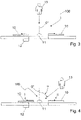
- the Figures 3 and 4 each show door systems 100 with sliding door leaves 10, and the movement of the door leaves 10 is controlled by the control unit 12.
- the sensor unit 11 is shown by way of example only on a proximity side of the door system 100; it can also be present on the exit side of the door system 100 in the same way.
- the person 13 approaches at an angle ⁇ to the vertical of 0°, and the example shows that the door leaf 10 on the side close to the person 13 is opened wider than the door leaf 10 on the side facing away from the close side.
- Door leaf 10 on the left side facing away from the approach nevertheless open by a certain distance, and door leaf 10 on the right side does not have to open fully either.
- the opening widths of both door leaves 10 ideally release a passage section of the movement tube of the person 13 as they pass through the door system 100 .
- the left door leaf 10 shows the smaller first opening width I and the right door leaf shows the larger second opening width II.
- the movement of the door leaves 10 is controlled via a control unit 12, which is electrically connected to the at least one sensor unit 11 in a manner not shown in detail.
- the sensor unit 11 is, for example, a radar sensor or a camera, which not only detects the presence of the person 13 is able, but the sensor unit 11 can also detect the distance between the person 13 and the door system 100 and the angle ⁇ at which the person 13 approaches the door system 100 .
- a radar sensor or a camera with a corresponding image evaluation can determine the approach speed of the person 13.
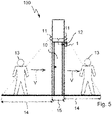
- figure 5 shows a door system 100 with a door operator 1 for operating a door leaf 10, and on both sides of the door system 100 a sensor unit 11 is arranged.
- One detection area 14 can be detected in each case with the sensor unit 11 , so that people 13 who are within the detection area 14 can be detected with the sensor units 11 .
- the sensor units 11 are designed so that a movement vector V can be determined, which results from an approach angle and the approach speed of the person 13, the approaches the door system 100.
- the movement vector V forms the parameter for the opening widths I, II, with which the door leaf or leaves 10 are to be opened; likewise, the opening speed of the door leaf 10 can be determined using the parameter based on the movement vector V.
- the movement vector V can be formed starting from the detection area 14 on the approach side to the end of the detection area 14 on the exit side of the door system 100 .
- the inner area 15, which cannot be detected with the sensor units 11, can be additionally determined by calculation. Consequently, from the two individual movement vectors V shown as an example, a continuous, single movement vector V can be determined, which is calculated in real time for each section of the inspection.
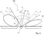
- FIG 6 shows a door arrangement 100 with a sensor unit 11 which is twisted in the direction of a closing side of the door leaf 10 .
- the sensor unit 11 is a radar sensor, for example, which is arranged in a fixed manner and is therefore no longer rotated, even during permanent operation of the door system 100 .
- the sensor unit 11 embodied as a radar sensor has a main detection range H, which has a central axis of 0° in the non-rotated arrangement, which is orthogonal to the door system 100 .
- This main detection range H extends, for example, from ⁇ 50° to +50° around 0°. If the sensor unit 11 is twisted by a twisting angle ⁇ , a twisted main detection area H′ also results. The then applicable 0° are drawn in dashed lines with the two limits of the main detection range H'.
- a wide zone Z1 and a narrow zone Z2 The areas next to the main detection area H′ that cannot be detected with full field strength or can no longer be detected are shown as a wide zone Z1 and a narrow zone Z2. If the sensor unit 11 were not twisted, both zones Z1 and Z2 would be of the same size. However, due to the twisting, a narrow zone Z2 results from the direction of the closing side of the door leaf 10, whereas the zone widens on the hinge side of the door leaf 10, so that a wider zone Z1 arises.
Landscapes
- Power-Operated Mechanisms For Wings (AREA)
Priority Applications (3)
| Application Number | Priority Date | Filing Date | Title |
|---|---|---|---|
| EP21156782.1A EP4043683A1 (fr) | 2021-02-12 | 2021-02-12 | Procédé de fonctionnement d'une installation de porte et installation de porte correspondante |
| US17/668,077 US11939809B2 (en) | 2021-02-12 | 2022-02-09 | Method for operating a door system and door system for same |
| CN202210121617.3A CN114922536A (zh) | 2021-02-12 | 2022-02-09 | 用于运行门设施的方法和用于实施该方法的门设施 |
Applications Claiming Priority (1)
| Application Number | Priority Date | Filing Date | Title |
|---|---|---|---|
| EP21156782.1A EP4043683A1 (fr) | 2021-02-12 | 2021-02-12 | Procédé de fonctionnement d'une installation de porte et installation de porte correspondante |
Publications (1)
| Publication Number | Publication Date |
|---|---|
| EP4043683A1 true EP4043683A1 (fr) | 2022-08-17 |
Family
ID=74595120
Family Applications (1)
| Application Number | Title | Priority Date | Filing Date |
|---|---|---|---|
| EP21156782.1A Pending EP4043683A1 (fr) | 2021-02-12 | 2021-02-12 | Procédé de fonctionnement d'une installation de porte et installation de porte correspondante |
Country Status (3)
| Country | Link |
|---|---|
| US (1) | US11939809B2 (fr) |
| EP (1) | EP4043683A1 (fr) |
| CN (1) | CN114922536A (fr) |
Cited By (1)
| Publication number | Priority date | Publication date | Assignee | Title |
|---|---|---|---|---|
| US20220316261A1 (en) * | 2021-03-30 | 2022-10-06 | Ford Global Technologies, Llc | Vehicle closure assembly actuating method and system |
Families Citing this family (3)
| Publication number | Priority date | Publication date | Assignee | Title |
|---|---|---|---|---|
| DE102020119925A1 (de) * | 2020-07-28 | 2022-02-03 | Bea Sa | Automatische Drehflügeltür und Sensor |
| US12159415B2 (en) * | 2022-02-09 | 2024-12-03 | Capital One Services, Llc | More efficient automatic door sensing |
| SE546983C2 (en) * | 2023-02-13 | 2025-03-25 | Assa Abloy Ab | Controlling a sliding door comprising a first door leaf and a second door leaf |
Citations (6)
| Publication number | Priority date | Publication date | Assignee | Title |
|---|---|---|---|---|
| EP0696670A1 (fr) * | 1994-08-11 | 1996-02-14 | Nabco Limited | Système pour ouverture et fermeture automatique des portes |
| DE19613178A1 (de) | 1996-04-02 | 1997-10-09 | Heinrich Landert | Verfahren zum Betrieb einer Türanlage und eine nach dem Verfahren arbeitende Türanlage |
| DE102007062473A1 (de) * | 2007-12-20 | 2009-07-02 | Technische Universität München | Tür, insbesondere Fahrzeugtür, mit wenigstens zwei kinematischen Freiheitsgraden und Verfahren zu ihrer Betätigung |
| EP2418517A2 (fr) * | 2010-08-09 | 2012-02-15 | Dorma GmbH&Co. Kg | Capteur optoélectronique |
| DE102018104202A1 (de) * | 2018-02-23 | 2019-08-29 | Marantec Antriebs- Und Steuerungstechnik Gmbh & Co. Kg | Verfahren zum Betrieb eines Torsystems sowie Torsystem |
| EP3613933A1 (fr) | 2018-08-22 | 2020-02-26 | GEZE GmbH | Dispositif de surveillance de portes, fenêtres ou analogues |
Family Cites Families (5)
| Publication number | Priority date | Publication date | Assignee | Title |
|---|---|---|---|---|
| DE19700811A1 (de) * | 1997-01-13 | 1998-07-16 | Heinrich Landert | Verfahren und Vorrichtung zur Ansteuerung von Türanlage in Abhängigkeit von der Anwesenheit von Personen |
| JP4267996B2 (ja) * | 2003-09-17 | 2009-05-27 | Thk株式会社 | 自動扉装置 |
| WO2009144841A1 (fr) * | 2008-05-28 | 2009-12-03 | Kimura Masaaki | Ouverture/fermeture de porte pivotante automatique en toute sécurité dans les directions droite et gauche |
| CN102747919B (zh) * | 2012-06-18 | 2014-11-12 | 浙江工业大学 | 基于全方位计算机视觉的人行自动门安全和节能控制装置 |
| DE102018208440A1 (de) * | 2018-05-29 | 2019-12-05 | Geze Gmbh | Vorrichtung zur sensorischen absicherung der flügelbewegungen einer automatischen drehtür |
-
2021
- 2021-02-12 EP EP21156782.1A patent/EP4043683A1/fr active Pending
-
2022
- 2022-02-09 CN CN202210121617.3A patent/CN114922536A/zh active Pending
- 2022-02-09 US US17/668,077 patent/US11939809B2/en active Active
Patent Citations (6)
| Publication number | Priority date | Publication date | Assignee | Title |
|---|---|---|---|---|
| EP0696670A1 (fr) * | 1994-08-11 | 1996-02-14 | Nabco Limited | Système pour ouverture et fermeture automatique des portes |
| DE19613178A1 (de) | 1996-04-02 | 1997-10-09 | Heinrich Landert | Verfahren zum Betrieb einer Türanlage und eine nach dem Verfahren arbeitende Türanlage |
| DE102007062473A1 (de) * | 2007-12-20 | 2009-07-02 | Technische Universität München | Tür, insbesondere Fahrzeugtür, mit wenigstens zwei kinematischen Freiheitsgraden und Verfahren zu ihrer Betätigung |
| EP2418517A2 (fr) * | 2010-08-09 | 2012-02-15 | Dorma GmbH&Co. Kg | Capteur optoélectronique |
| DE102018104202A1 (de) * | 2018-02-23 | 2019-08-29 | Marantec Antriebs- Und Steuerungstechnik Gmbh & Co. Kg | Verfahren zum Betrieb eines Torsystems sowie Torsystem |
| EP3613933A1 (fr) | 2018-08-22 | 2020-02-26 | GEZE GmbH | Dispositif de surveillance de portes, fenêtres ou analogues |
Cited By (1)
| Publication number | Priority date | Publication date | Assignee | Title |
|---|---|---|---|---|
| US20220316261A1 (en) * | 2021-03-30 | 2022-10-06 | Ford Global Technologies, Llc | Vehicle closure assembly actuating method and system |
Also Published As
| Publication number | Publication date |
|---|---|
| US11939809B2 (en) | 2024-03-26 |
| US20220268083A1 (en) | 2022-08-25 |
| CN114922536A (zh) | 2022-08-19 |
Similar Documents
| Publication | Publication Date | Title |
|---|---|---|
| EP4043683A1 (fr) | Procédé de fonctionnement d'une installation de porte et installation de porte correspondante | |
| EP4153837B1 (fr) | Procédé et appareil permettant de commander un système de porte automatique | |
| EP2437962B1 (fr) | Methode et dispositif pour actionner un ouvrnat d'un véhicule | |
| EP0853299B2 (fr) | Procédé et dispositif de commande d'un aménagement pour porte en réponse à la présence des personnes | |
| DE102008044990B4 (de) | Verfahren und Vorrichtung zur Ansteuerung und/oder Überwachung eines motorisch angetriebenen Flügels während der Öffnungsphase | |
| DE19613178A1 (de) | Verfahren zum Betrieb einer Türanlage und eine nach dem Verfahren arbeitende Türanlage | |
| EP3575534B1 (fr) | Dispositif de sécurisation sensorielle des mouvements de battant d'une porte tournante automatique | |
| EP3581747B1 (fr) | Dispositif de surveillance | |
| EP4043688A1 (fr) | Actionneur de porte et procédé de fonctionnement d'un actionneur de porte | |
| DE19804632C2 (de) | Verfahren und Vorrichtung zur Ansteuerung und/oder Überwachung eines motorisch angetriebenen Flügels | |
| EP2531684B1 (fr) | Dispositif d'entraînement de porte, fermeture de bâtiment ainsi équipée, système de porte et procédé de fabrication et d'entraînement | |
| WO2016012631A1 (fr) | Procédé de surveillance | |
| EP4043682A1 (fr) | Procédé de fonctionnement d'une installation de porte | |
| EP0935045A2 (fr) | Procédé et dispositif de commande et/ou de surveillance d'une porte motorisée | |
| EP3680814B1 (fr) | Procédé de détection des déroulements de mouvements et système de détection correspondant | |
| EP4043686B1 (fr) | Procédé de fonctionnement d'un actionneur de porte | |
| EP0935042B1 (fr) | Procédé et dispositif de commande et/ou de surveillance d'une porte motorisée | |
| WO2016113367A1 (fr) | Procédé de fonctionnement d'un entraînement de porte, commande d'entraînement de porte, entraînement de porte et porte à battant tournant | |
| EP4043687A1 (fr) | Procédé de fonctionnement d'un actionneur de porte | |
| DE4337015B4 (de) | Verfahren zur Steuerung eines motorischen Antriebs einer Tür- oder Fensteranlage | |
| EP4321721A1 (fr) | Procédé permettant de faire fonctionner une installation de porte et installation de porte correspondante | |
| EP4257530A1 (fr) | Dispositif capteur destiné à la commande de porte | |
| EP4321720A1 (fr) | Procédé de fonctionnement d'un actionneur de porte | |
| DE102015104825A1 (de) | Verfahren zum Betreiben eines Türantriebs, Türantriebssteuerung, Türantrieb und Drehflügeltür | |
| DE19804573C1 (de) | Verfahren und Vorrichtung zur Ansteuerung und/oder Überwachung eines motorisch angetriebenen Flügels |
Legal Events
| Date | Code | Title | Description |
|---|---|---|---|
| PUAI | Public reference made under article 153(3) epc to a published international application that has entered the european phase |
Free format text: ORIGINAL CODE: 0009012 |
|
| STAA | Information on the status of an ep patent application or granted ep patent |
Free format text: STATUS: THE APPLICATION HAS BEEN PUBLISHED |
|
| AK | Designated contracting states |
Kind code of ref document: A1 Designated state(s): AL AT BE BG CH CY CZ DE DK EE ES FI FR GB GR HR HU IE IS IT LI LT LU LV MC MK MT NL NO PL PT RO RS SE SI SK SM TR |
|
| STAA | Information on the status of an ep patent application or granted ep patent |
Free format text: STATUS: REQUEST FOR EXAMINATION WAS MADE |
|
| 17P | Request for examination filed |
Effective date: 20230215 |
|
| RBV | Designated contracting states (corrected) |
Designated state(s): AL AT BE BG CH CY CZ DE DK EE ES FI FR GB GR HR HU IE IS IT LI LT LU LV MC MK MT NL NO PL PT RO RS SE SI SK SM TR |
|
| STAA | Information on the status of an ep patent application or granted ep patent |
Free format text: STATUS: EXAMINATION IS IN PROGRESS |
|
| 17Q | First examination report despatched |
Effective date: 20230718 |
|
| APBN | Date of receipt of notice of appeal recorded |
Free format text: ORIGINAL CODE: EPIDOSNNOA2E |
|
| APAV | Appeal reference deleted |
Free format text: ORIGINAL CODE: EPIDOSDREFNE |
|
| APAF | Appeal reference modified |
Free format text: ORIGINAL CODE: EPIDOSCREFNE |
|
| APBR | Date of receipt of statement of grounds of appeal recorded |
Free format text: ORIGINAL CODE: EPIDOSNNOA3E |
|
| APAF | Appeal reference modified |
Free format text: ORIGINAL CODE: EPIDOSCREFNE |