EP2422919A1 - Matériau de soudage à base d'austénite, procédé d'entretien préventif contre la corrosion fissurante sous tension et procédé d'entretien préventif contre la corrosion intercristalline utilisant ce dernier - Google Patents
Matériau de soudage à base d'austénite, procédé d'entretien préventif contre la corrosion fissurante sous tension et procédé d'entretien préventif contre la corrosion intercristalline utilisant ce dernier Download PDFInfo
- Publication number
- EP2422919A1 EP2422919A1 EP09833449A EP09833449A EP2422919A1 EP 2422919 A1 EP2422919 A1 EP 2422919A1 EP 09833449 A EP09833449 A EP 09833449A EP 09833449 A EP09833449 A EP 09833449A EP 2422919 A1 EP2422919 A1 EP 2422919A1
- Authority
- EP
- European Patent Office
- Prior art keywords
- welding
- overlay
- welding material
- less
- stainless steel
- Prior art date
- Legal status (The legal status is an assumption and is not a legal conclusion. Google has not performed a legal analysis and makes no representation as to the accuracy of the status listed.)
- Granted
Links
Images


Classifications
-
- B—PERFORMING OPERATIONS; TRANSPORTING
- B23—MACHINE TOOLS; METAL-WORKING NOT OTHERWISE PROVIDED FOR
- B23K—SOLDERING OR UNSOLDERING; WELDING; CLADDING OR PLATING BY SOLDERING OR WELDING; CUTTING BY APPLYING HEAT LOCALLY, e.g. FLAME CUTTING; WORKING BY LASER BEAM
- B23K35/00—Rods, electrodes, materials, or media, for use in soldering, welding, or cutting
- B23K35/22—Rods, electrodes, materials, or media, for use in soldering, welding, or cutting characterised by the composition or nature of the material
- B23K35/24—Selection of soldering or welding materials proper
- B23K35/30—Selection of soldering or welding materials proper with the principal constituent melting at less than 1550°C
- B23K35/3053—Fe as the principal constituent
-
- B—PERFORMING OPERATIONS; TRANSPORTING
- B23—MACHINE TOOLS; METAL-WORKING NOT OTHERWISE PROVIDED FOR
- B23K—SOLDERING OR UNSOLDERING; WELDING; CLADDING OR PLATING BY SOLDERING OR WELDING; CUTTING BY APPLYING HEAT LOCALLY, e.g. FLAME CUTTING; WORKING BY LASER BEAM
- B23K35/00—Rods, electrodes, materials, or media, for use in soldering, welding, or cutting
- B23K35/22—Rods, electrodes, materials, or media, for use in soldering, welding, or cutting characterised by the composition or nature of the material
- B23K35/24—Selection of soldering or welding materials proper
- B23K35/30—Selection of soldering or welding materials proper with the principal constituent melting at less than 1550°C
-
- B—PERFORMING OPERATIONS; TRANSPORTING
- B23—MACHINE TOOLS; METAL-WORKING NOT OTHERWISE PROVIDED FOR
- B23K—SOLDERING OR UNSOLDERING; WELDING; CLADDING OR PLATING BY SOLDERING OR WELDING; CUTTING BY APPLYING HEAT LOCALLY, e.g. FLAME CUTTING; WORKING BY LASER BEAM
- B23K31/00—Processes relevant to this subclass, specially adapted for particular articles or purposes, but not covered by any single one of main groups B23K1/00 - B23K28/00
-
- B—PERFORMING OPERATIONS; TRANSPORTING
- B23—MACHINE TOOLS; METAL-WORKING NOT OTHERWISE PROVIDED FOR
- B23K—SOLDERING OR UNSOLDERING; WELDING; CLADDING OR PLATING BY SOLDERING OR WELDING; CUTTING BY APPLYING HEAT LOCALLY, e.g. FLAME CUTTING; WORKING BY LASER BEAM
- B23K31/00—Processes relevant to this subclass, specially adapted for particular articles or purposes, but not covered by any single one of main groups B23K1/00 - B23K28/00
- B23K31/12—Processes relevant to this subclass, specially adapted for particular articles or purposes, but not covered by any single one of main groups B23K1/00 - B23K28/00 relating to investigating the properties, e.g. the weldability, of materials
-
- B—PERFORMING OPERATIONS; TRANSPORTING
- B23—MACHINE TOOLS; METAL-WORKING NOT OTHERWISE PROVIDED FOR
- B23K—SOLDERING OR UNSOLDERING; WELDING; CLADDING OR PLATING BY SOLDERING OR WELDING; CUTTING BY APPLYING HEAT LOCALLY, e.g. FLAME CUTTING; WORKING BY LASER BEAM
- B23K9/00—Arc welding or cutting
- B23K9/04—Welding for other purposes than joining, e.g. built-up welding
-
- B—PERFORMING OPERATIONS; TRANSPORTING
- B23—MACHINE TOOLS; METAL-WORKING NOT OTHERWISE PROVIDED FOR
- B23K—SOLDERING OR UNSOLDERING; WELDING; CLADDING OR PLATING BY SOLDERING OR WELDING; CUTTING BY APPLYING HEAT LOCALLY, e.g. FLAME CUTTING; WORKING BY LASER BEAM
- B23K9/00—Arc welding or cutting
- B23K9/23—Arc welding or cutting taking account of the properties of the materials to be welded
-
- C—CHEMISTRY; METALLURGY
- C21—METALLURGY OF IRON
- C21D—MODIFYING THE PHYSICAL STRUCTURE OF FERROUS METALS; GENERAL DEVICES FOR HEAT TREATMENT OF FERROUS OR NON-FERROUS METALS OR ALLOYS; MAKING METAL MALLEABLE, e.g. BY DECARBURISATION OR TEMPERING
- C21D9/00—Heat treatment, e.g. annealing, hardening, quenching or tempering, adapted for particular articles; Furnaces therefor
- C21D9/50—Heat treatment, e.g. annealing, hardening, quenching or tempering, adapted for particular articles; Furnaces therefor for welded joints
-
- C—CHEMISTRY; METALLURGY
- C21—METALLURGY OF IRON
- C21D—MODIFYING THE PHYSICAL STRUCTURE OF FERROUS METALS; GENERAL DEVICES FOR HEAT TREATMENT OF FERROUS OR NON-FERROUS METALS OR ALLOYS; MAKING METAL MALLEABLE, e.g. BY DECARBURISATION OR TEMPERING
- C21D9/00—Heat treatment, e.g. annealing, hardening, quenching or tempering, adapted for particular articles; Furnaces therefor
- C21D9/50—Heat treatment, e.g. annealing, hardening, quenching or tempering, adapted for particular articles; Furnaces therefor for welded joints
- C21D9/505—Cooling thereof
-
- C—CHEMISTRY; METALLURGY
- C22—METALLURGY; FERROUS OR NON-FERROUS ALLOYS; TREATMENT OF ALLOYS OR NON-FERROUS METALS
- C22C—ALLOYS
- C22C38/00—Ferrous alloys, e.g. steel alloys
- C22C38/001—Ferrous alloys, e.g. steel alloys containing N
-
- C—CHEMISTRY; METALLURGY
- C22—METALLURGY; FERROUS OR NON-FERROUS ALLOYS; TREATMENT OF ALLOYS OR NON-FERROUS METALS
- C22C—ALLOYS
- C22C38/00—Ferrous alloys, e.g. steel alloys
- C22C38/004—Very low carbon steels, i.e. having a carbon content of less than 0,01%
-
- C—CHEMISTRY; METALLURGY
- C22—METALLURGY; FERROUS OR NON-FERROUS ALLOYS; TREATMENT OF ALLOYS OR NON-FERROUS METALS
- C22C—ALLOYS
- C22C38/00—Ferrous alloys, e.g. steel alloys
- C22C38/02—Ferrous alloys, e.g. steel alloys containing silicon
-
- C—CHEMISTRY; METALLURGY
- C22—METALLURGY; FERROUS OR NON-FERROUS ALLOYS; TREATMENT OF ALLOYS OR NON-FERROUS METALS
- C22C—ALLOYS
- C22C38/00—Ferrous alloys, e.g. steel alloys
- C22C38/04—Ferrous alloys, e.g. steel alloys containing manganese
-
- C—CHEMISTRY; METALLURGY
- C22—METALLURGY; FERROUS OR NON-FERROUS ALLOYS; TREATMENT OF ALLOYS OR NON-FERROUS METALS
- C22C—ALLOYS
- C22C38/00—Ferrous alloys, e.g. steel alloys
- C22C38/18—Ferrous alloys, e.g. steel alloys containing chromium
- C22C38/40—Ferrous alloys, e.g. steel alloys containing chromium with nickel
- C22C38/50—Ferrous alloys, e.g. steel alloys containing chromium with nickel with titanium or zirconium
-
- C—CHEMISTRY; METALLURGY
- C22—METALLURGY; FERROUS OR NON-FERROUS ALLOYS; TREATMENT OF ALLOYS OR NON-FERROUS METALS
- C22C—ALLOYS
- C22C38/00—Ferrous alloys, e.g. steel alloys
- C22C38/18—Ferrous alloys, e.g. steel alloys containing chromium
- C22C38/40—Ferrous alloys, e.g. steel alloys containing chromium with nickel
- C22C38/54—Ferrous alloys, e.g. steel alloys containing chromium with nickel with boron
-
- F—MECHANICAL ENGINEERING; LIGHTING; HEATING; WEAPONS; BLASTING
- F16—ENGINEERING ELEMENTS AND UNITS; GENERAL MEASURES FOR PRODUCING AND MAINTAINING EFFECTIVE FUNCTIONING OF MACHINES OR INSTALLATIONS; THERMAL INSULATION IN GENERAL
- F16J—PISTONS; CYLINDERS; SEALINGS
- F16J12/00—Pressure vessels in general
-
- C—CHEMISTRY; METALLURGY
- C21—METALLURGY OF IRON
- C21D—MODIFYING THE PHYSICAL STRUCTURE OF FERROUS METALS; GENERAL DEVICES FOR HEAT TREATMENT OF FERROUS OR NON-FERROUS METALS OR ALLOYS; MAKING METAL MALLEABLE, e.g. BY DECARBURISATION OR TEMPERING
- C21D2211/00—Microstructure comprising significant phases
- C21D2211/001—Austenite
-
- C—CHEMISTRY; METALLURGY
- C21—METALLURGY OF IRON
- C21D—MODIFYING THE PHYSICAL STRUCTURE OF FERROUS METALS; GENERAL DEVICES FOR HEAT TREATMENT OF FERROUS OR NON-FERROUS METALS OR ALLOYS; MAKING METAL MALLEABLE, e.g. BY DECARBURISATION OR TEMPERING
- C21D2251/00—Treating composite or clad material
- C21D2251/04—Welded or brazed overlays
Definitions
- the present invention relates to an austenitic welding material, and a preventive maintenance method for stress corrosion cracking and a preventive maintenance method for intergranular (grain boundary) corrosion, using the welding material.
- the present invention relates to a welding material suitable for welding of austenitic stainless steel equipment, piping or the like, for example, in a nuclear power plant, a method for performing preventive maintenance against stress corrosion cracking of the equipment, piping or the like, using the welding material, and a method for performing preventive maintenance against intergranular corrosion of the equipment, piping or the like, using the welding material.
- austenitic stainless steel such as SUS 316L, SUS 304 or SUS 347
- SUS 316L, SUS 304 or SUS 347 is used as a structural material for equipment, piping or the like, including a reactor pressure vessel and reactor internal components.
- intergranular corrosion or stress corrosion cracking is likely to occur in a heat-affected zone adjacent to a weld.
- the stress corrosion cracking is known as a phenomenon which occurs when an environmental condition, a stress condition and sensitization in the material are superimposed.
- the term "sensitization of austenitic stainless steel” means a phenomenon that, when the stainless steel is heated at a temperature of 450 to 800°C for a long period of time, solid-solved carbons are precipitated as chromium carbides in grain boundaries, and thereby a region deficient in solid-solved chromium is formed in the vicinity of the grain boundaries, which causes deterioration in corrosion resistance of a steel member.
- a welding heat-affected zone between a weld toe and a base metal is sensitized due to a welding heat input.
- Patent Document 10 a technique of simultaneously preventing the stress corrosion cracking in inner and outer surfaces of a pipe. More specifically, it is a method designed for preventive maintenance using a laser irradiation unit which is adapted to perform a rapid solidification process for forming a rapidly-solidified microstructure in an inner surface of a target member, while reducing a residual stress in an outer surface of the target member, or a solution heat treatment for reducing respective residual stresses in an inner and outer surfaces of a target member.
- this technique is likely to fail to sufficiently shift a residual stress in the outer surface of a weld toward a compressive side. Moreover, if the laser irradiation power becomes excessively large, the laser irradiation is likely to cause a new sensitized region.
- this technique is applied to nuclear reactor internal piping, when the piping undergoes high-dose neutron irradiation during nuclear reactor operation, helium (He) produced by a nuclear reaction will be accumulated inside the piping. Thus, there is concern that He-induced cracking occurs when a large amount of heat is applied to a weld of the piping.
- the Patent Document 6 describes a stress-corrosion-cracking prevention technique, wherein, in an operation of butt-welding two stainless steel pipes, a melting/solidification process or an overlay welding process is performed in a depth range of 0.1 mm to 1.0 mm from an inner or outer surface of a base metal, to form a solidified layer.
- the solidified layer has the same chemical composition as that of the base metal.
- the conventional stress-corrosion-cracking prevention techniques and the conventional repair techniques are just intended to: perform welding using a commercially-available welding material so as to prevent damage of a weld joint itself; coat a final layer of a weld joint with a commercially-available stress corrosion cracking-resistant alloy; clad a heat-affected zone generated in a weld joint itself, with a commercially-available cladding alloy; or re-weld a cladding region, or a portion of a weld joint including a non-welding base metal subjected to removal of cracking or other defect, using a commercially-available welding material.
- Newly deposited welding material itself does not have a sufficient stress corrosion cracking resistance, during a long-term plant operation, particularly, in a welded junction or the vicinity thereof, in a region having a high electrochemical potential or a region irradiated with a high neutron flux, more particularly, in a bead along a weld edge where the commercially-available welding material is diluted with a composition of the base metal.
- the conventional stress-corrosion-cracking prevention techniques and the conventional repair techniques have a problem of re-occurrence of the stress corrosion cracking.
- an existing an overlay-welding material involves the following problems. Characteristics necessary for a weld joint include a stress corrosion cracking resistance of a heat-affected zone, and a cracking resistance of a deposited metal zone. It is also necessary for an overlay weld to have a cracking resistance. However, in cases where overlay welding is performed to form a multi-layer overlay weld, i.e., two or more weld layers, bending crack often occurs in a first weld layer or an underlaying weld layer. Therefore, in existing welding materials widely used for overlay welding, such as Y308 series, a composition thereof is adjusted to form ⁇ -ferrite or the like so as to become a deposited metal improved in solidification cracking sensitivity.
- an austenitic welding material which contains C: 0.01 wt% or less, Si: 0.5 wt% or less, Mn: 0.5 wt% or less, P: 0.005 wt% or less, S: 0.005 wt% or less, Ni: 15 to 40 wt%, Cr: 20 to 30 wt%, N: 0.01 wt% or less, O: 0.01 wt% or less, and the balance of Fe and inevitable impurities, wherein the content of B contained as one of the inevitable impurities in the welding material is 3 wt ppm or less, and the total content of C, P, S, N and O in the welding material is 0.02 wt% or less.
- a preventive maintenance method for stress corrosion cracking of a structure formed by welding austenitic stainless steel members together comprises an overlay welding step of overlay-welding the above welding material to a surface of a welding heat-affected zone of the structure to form an overlay weld thereon.
- a preventive maintenance method for stress corrosion cracking of a structure formed by welding and joining at least a first austenitic stainless steel member and a second austenitic stainless steel member comprises the steps of: separating the second austenitic stainless steel member used in the structure and to be replaced with a countermeasure member, from the first austenitic stainless steel member, and detaching the second austenitic stainless steel member from the structure; overlay-welding the above welding material to each of a groove surface of the countermeasure member and a groove surface of the first austenitic stainless steel member; and welding and joining the overlay-welded groove surface of the countermeasure member and the overlay-welded groove surface of the first austenitic stainless steel member.
- a preventive maintenance method for intergranular corrosion of an austenitic stainless steel structure contactable with a corrosive fluid comprises a step of overlay-welding the above welding material to a surface of the structure contactable with the corrosive fluid, to form an overlay weld thereon so as to prevent contact with the corrosive fluid.
- the inventors firstly studied an influence of a content of boron (B) added to a welding material (austenitic stainless steel) on a stress corrosion cracking resistance and an intergranular corrosion resistance.
- JP 63-69947A discloses that creep rupture ductility is improved by adding B to austenitic stainless steel in an amount of 6 to 25 ppm. It is also disclosed that, when B is added in an amount of 25 ppm, a corrosion resistance of the austenitic stainless steel is deteriorated. Further, in “ Stainless steel '87", the institute of Metals, London, (1987), p.
- the inventors acquired knowledge that, as a prerequisite to improving a stress corrosion cracking resistance and an intergranular corrosion resistance under the above environments, it is critical to further reduce the B content.
- a solid solubility limit of B in austenitic stainless steel is assumed to be about 10 ppm, a significant improvement in grain-boundary damage is observed even when the B content is less than the solid solubility limit, and acquired knowledge that a development of intergranular corrosion is not caused by formation of borides but by B itself solid-solved in grain boundaries.
- the inventers studied factors causing stress corrosion cracking and intergranular corrosion in a weld formed by performing multi-layer overlay welding, under a high-temperature/high-pressure underwater environment undergoing neutron irradiation and under a corrosive environment between a boiling heat transfer surface and a high-concentration nitric acid solution including a highly-acid ion.
- the inventors acquired knowledge that, in typical welding, a heat-affected zone (welding heat-affected zone in a base metal) is sensitized, whereas, in two-layer or multi-layer overlay welding, an overlay weld is sensitized to stress corrosion cracking and intergranular corrosion, because Cr-based carbides are precipitated in grain boundaries of the overlay weld as well as the base metal, under an influence of heat from subsequent bead welding or the like, and thereby, if the B content is 5 ppm or more, it becomes impossible to fully avoid the stress corrosion cracking under a high-temperature/high-pressure underwater environment undergoing neutron irradiation, and the transpassive corrosion under a corrosive environment between a boiling heat transfer surface and a high-concentration nitric acid solution including a highly-acid ion.
- the inventors also acquired knowledge that, particularly when overlay welding is performed using an existing welding material (commercially-available welding material), welded members are further sensitized.
- impurity elements such as boron (B) and carbon (C)
- the inventers checked a stress corrosion cracking resistance and an intergranular corrosion resistance of a welded junction under the two environments, by preparing an austenitic welding material which contains C: 0.01 wt% or less, Si: 0.5 wt% or less, Mn: 0.5 wt% or less, P: 0.005 wt% or less, S: 0.005 wt% or less, Ni: 15 to 40 wt%, Cr: 20 to 30 wt%, N: 0.01 wt% or less, O: 0.01 1 wt% or less, and the balance of Fe and inevitable impurities, wherein the content of B contained as one of the inevitable impurities is 3 wt ppm or less, and the total content of C, P, S, N and O is 0.02 wt% or less, and overlay-welding the welding material to a butt weld.
- an austenitic welding material which contains C: 0.01 wt% or less, Si: 0.5 wt% or less
- the inventors found out that the above austenitic welding material provides a significant improvement in stress corrosion cracking resistance and intergranular corrosion resistance of a welded junction, as compared with the existing welding material. Based on this knowledge, the present invention has been accomplished.
- One embodiment of an austenitic welding material according to the present invention contains C: 0.01 wt% or less, Si: 0.5 wt% or less, Mn: 0.5 wt% or less, P: 0.005 wt% or less, S: 0.005 wt% or less, Ni: 15 to 40 wt%, Cr: 20 to 30 wt%, N: 0.01 wt% or less, O: 0.01 wt% or less, and the balance of Fe and inevitable impurities, wherein the content of B contained as one of the inevitable impurities in the welding material is 3 wt ppm or less, and the total content of C, P, S, N and O in the welding material is 0.02 wt% or less.
- a metal structure of the welding material in this embodiment comprises austenite (austenitic structure), at normal temperature and normal pressure (25°C, 1 atm).
- An austenitic welding material having a low amount of impurity elements such as B and C i.e., highly-purified austenitic welding material
- B and C i.e., highly-purified austenitic welding material
- a temperature rise of a base metal can be suppressed to a low level, so that it becomes possible to narrow a welding heat-affected zone, i.e., a sensitized zone.
- solidification of a weld will be promptly completed.
- a thermal shrinkage of the weld with respect to a base metal region becomes larger, and the weld is placed in a compressive residual stress state. This makes it possible to improve a stress corrosion cracking resistance.
- the metal structure of the welding material of this embodiment consists only of austenite.
- Carbon (C) is an element which causes Cr-base carbides to be precipitated in grain boundaries during heating. Based on the precipitation, a Cr-deficient region is formed around the carbide, which causes deterioration in nitric-acid corrosion resistance and stress corrosion cracking resistance in grain boundaries. Thus, it is desirable to minimize a C content in the welding material. Considering industrial practicality of a dissolution process and others, the C content is set to 0.01 wt% or less.
- Silicon (Si) is an element which allows a nitric acid resistance of a welding material to be improved when it is added to the welding material within several wt%. However, in view of suppressing grain-boundary damage, it is desirable to minimize a Si content in the welding material. On the other hand, a certain amount of Si is effective as an oxygen enrichment inhibitor for a molten material pool. Thus, the Si content is set to 0.5 wt% or less.
- Manganese (Mn) is an element capable of enhancing stability of an austenite phase, and preventing formation of ⁇ -ferrite harmful to a corrosion resistance, and processing-induced phase transformation. However, if a Mn content in the welding material becomes greater than 0.5 wt%, the ⁇ -ferrite formation and processing-induced phase transformation preventing effect of Mn is saturated. Rather, a large amount of Mn solid-solved in an austenite phase promotes the corrosion. Thus, the Mn content is set to 0.5 wt% or less.
- Phosphorus (P) is known as an element having a property of being segregated in grain boundaries. As a P content in the welding material is increased, the stress corrosion cracking resistance and intergranular corrosion resistance in grain boundaries become deteriorated. Thus, it is desirable to minimize the P content. Practically, the P content is set to 0.005 wt% or less.
- S Sulfur
- S is an element which causes formation of a sulfide in a welding material.
- S content in the welding material is increased, the formation of sulfides is further promoted. Consequently, due to selective corrosion triggered by the sulfides, the stress corrosion cracking resistance, the intergranular corrosion resistance and a pitting corrosion of the welding material become deteriorated. Thus, it is desirable to minimize the S content. Practically, the S content is set to 0.005 wt% or less.
- Nickel (Ni) is an element necessary for stabilizing austenite of the welding material and suppressing the stress corrosion cracking and intergranular corrosion.
- a Ni content in the welding material is less than 15 wt%, it becomes impossible to ensure austenite in the metal structure in an amount enough to suppress the stress corrosion cracking and intergranular corrosion, and obtain a swelling resistance under a neutron irradiation environment.
- the Ni content becomes greater than 40 wt%, a raw material cost of the welding material is increased.
- the Ni content is set in the range of 15 to 40 wt%.
- Chromium (Cr) is an element necessary for forming a passive film on a surface of a welding material to ensure the corrosion resistance.
- a Cr content in the welding material may be about 16 wt% as in SUS 304 and SUS 316 series stainless steels which are representative stainless steels in the Japanese Industrial Standards (JIS).
- the welding material As a prerequisite to allowing the welding material to ensure a sufficient corrosion resistance under a high-temperature/high-pressure underwater environment undergoing neutron irradiation, as in a core of a light-water nuclear reactor, and under a transpassive corrosion environment between a boiling heat transfer surface and a high-concentration nitric acid solution including a highly-acid ion, as in a reprocessing plant, it is necessary to set the Cr content to at least 20 wt%. On the other hand, if the Cr content becomes greater than 30 wt%, a Cr-rich brittle phase is precipitated in the welding material.
- the Cr content is set in the range of 20 to 30 wt%.
- Each of nitrogen (N) and oxygen (O) is an element which causes deterioration in the stress corrosion cracking resistance and intergranular corrosion resistance. Thus, it is desirable to minimize each of a N content and an O content in the welding material. Practically, each of the N content and the O content is set to 0.01 wt% or less.
- Boron (B) in the welding material is fundamentally an impurity element having a property of being segregated in brain boundaries to cause deterioration in the stress corrosion cracking resistance and intergranular corrosion resistance. Thus, it is desirable to minimize a B content in the welding material.
- the B content is one most important factor having an impact on the intergranular corrosion resistance and stress corrosion cracking resistance of the welding material in this embodiment.
- a success factor in allowing the inventors to acquire the knowledge about the advantageous effect of reducing the content of B to an extremely small value largely depends on progress in analysis device/technique and steelmaking technique.
- a detection limit in conventional analyses was about 2 wt ppm.
- the inventors have fully utilized recent analysis techniques successfully so as to clarify a relationship between a lower B content and the corrosion resistance, and finally found that the stress corrosion cracking resistance and intergranular corrosion resistance can be sufficiently suppressed when the B content is set to 0.0003 wt% or less.
- the B content is set to 3 wt ppm (0.0003 wt%) or less, preferably 1.5 wt ppm or less.
- B is mixed therein from raw materials, such as ferrous alloy and scrap, so that an obtained ingot inevitably has a B content of about 2 to 5 wt ppm.
- raw materials such as ferrous alloy and scrap
- B content of about 2 to 5 wt ppm.
- oxidation refining it has become possible to perform casting of steel having a low B content (so-called "low-B steel").
- the welding material does not exhibit adequate stress corrosion cracking resistance and intergranular corrosion resistance, if the total content of the elements is greater than 0.02 wt%. While the above elements are different from each other in terms of an effect on grain boundaries (influence on the stress corrosion cracking resistance and intergranular corrosion resistance) and a mechanism for forming a deposit, current analysis/evaluation techniques are incapable of distinguishing respective present states of the elements each having an extremely small amount, individually. However, it can be inferred that the impurity elements segregated/solid-solved in grain boundaries definitely have a negative effect. Thus, it is desirable to minimize a sum of the contents of the elements. Specifically, the sum of the C, P, S, N and O contents in the welding material is set to 0.02 wt% or less.
- an element capable of allowing the above impurity elements to become harmless to the stress corrosion cracking and intergranular corrosion preferably, add Ti.
- Ti so as to allow impurity elements causing the intergranular corrosion, such as C, P, S, N and O, to be precipitated in a deposited metal in the form of Ti-based carbides, Ti-based phosphides, Ti-based sulfides, Ti-based nitrides, Ti-based oxides and other Ti-based compounds, such as TiC, FeTiP, TiS, TiN and TiO 2 to render the impurity elements harmless to the stress corrosion cracking and intergranular corrosion.
- a Ti content is equal to or greater than an amount required for allowing all of C, P, S, N and O in the welding material to be precipitated in a deposited metal by welding in the form of Ti-based carbides, Ti-based phosphides, Ti-based sulfides, Ti-based nitrides, Ti-based oxides and other Ti-based compounds, such as TiC, FeTiP, TiS, TiN and TiO 2 .
- the Ti content is equal to or greater than a sum of a C content in terms of Ti equivalent (a Ti content stoichiometrically equal to a carbon content in the welding material), a P content in terms of Ti equivalent, a S content in terms of Ti equivalent, a N content in terms of Ti equivalent and an O content in terms of Ti equivalent.
- the Ti content is set to 0.05 wt% or more.
- excessive addition leads to an increase in raw material cost of the welding material.
- FIG. 1 is an explanatory diagram of an embodiment of a stress-corrosion-cracking preventive maintenance method according to the present invention, specifically, a sectional view of a weld joint test member, which schematically illustrates an overlay weld 1 formed by overlay-welding the welding material in the above-mentioned embodiment to a surface of a welded junction P contactable with nuclear reactor coolant (on the side of reactor coolant), during welding of SUS 304 stainless steel (austenitic stainless steel) piping for use in a nuclear reactor plant).
- SUS 304 stainless steel austenitic stainless steel
- the welding material in the above-mentioned embodiment is overlay-welded to a reactor coolant-side surface of the welded junction P and a base metal, to form an overlay weld 1 thereon.
- the overlay weld 1 entirely covers the welded junction P including the welding heat-affected zone 5, so that it becomes possible to effectively prevent the occurrence and development of stress corrosion cracking in the piping.
- the stress-corrosion-cracking preventive maintenance method in this embodiment makes it possible to effectively prevent the occurrence and development of stress corrosion cracking in the welded junction P of the piping for use in a nuclear reactor plant.
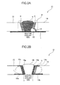
- FIG. 2 is an explanatory diagram of another embodiment of the stress-corrosion-cracking preventive maintenance method according to the present invention, specifically, a sectional view schematically illustrating a pipe 21 and a pipe 31 each overlay-welded with the welding material in the above-mentioned embodiment.
- FIG. 2A is a sectional view schematically illustrating a situation where a plurality of austenitic stainless steel members such as SUS 304 stainless steel pipe members (pipe members 13, 14) are welded and joined together, and exposed to nuclear reactor coolant within a nuclear reactor whereafter, when a defect such as intergranular corrosion or stress corrosion cracking, the defective portion is removed and repair-welded, and then overlay welding is performed using the welding material in the above-mentioned embodiment.
- a defect such as intergranular corrosion or stress corrosion cracking
- a defective portion existing in the welded junction P is removed, and then repair welding is performed using the same Y308 as that during the butt welding (to form a repair portion 10).
- overlay welding is performed using the welding material in the above-mentioned embodiment to coat the heat-affected zone 5, the weld metal 4, the repair portion 10 and a new heat-affected zone 12.
- both the heat-affected zone 5 and the new heat-affected zone 12 in the welded junction P are coated with the overlay weld 1. This makes it possible to effectively prevent the occurrence and development of stress corrosion cracking not only in the heat-affected zone 5 but also in the repair-welded portion (repair portion 10) and the heat-affected zone 12 caused by the repair welding.
- FIG. 2B is a sectional view schematically illustrating a situation where, when a defect such as intergranular corrosion or stress corrosion cracking is found in the pipe member 13 (austenitic stainless steel pipe) illustrated in FIG.2A , due to exposure to nuclear reactor coolant within a nuclear reactor, the defective pipe member 13 is replaced with a countermeasure member 15.
- a defect such as intergranular corrosion or stress corrosion cracking
- the pipe member 13 (which is a second austenitic stainless steel member) is firstly separated from the pipe member 14 (which is a first austenitic stainless steel member) joined to the pipe member 13. Then, the countermeasure member 15 made of the same material (SUS 304 stainless steel) as that of the pipe member 13 is prepared as a substitute for the pipe member 13 from which a defect is found, and the welding material in the above-mentioned embodiment is overlay-welded to a groove surface 15a of the countermeasure member 15 and two pipe surfaces 15b, 15c of the countermeasure member 15 adjacent to the groove surface 15a.
- each of the pipe surface 15b and the pipe surface 14b is a reactor coolant-side surface of a respective one of the countermeasure member 15 and the pipe member 14
- each of the pipe surface 15c and the pipe surface 14c is a surface of a respective one of the countermeasure member 15 and the pipe member 14 on an opposite side of the reactor coolant-side surface.
- a reactor coolant-side one of the surfaces is greater than the other surface.
- the welding material in the above-mentioned embodiment is overlay-welded to the groove surfaces.
- the butt welding it becomes possible to suppress sensitization which would otherwise occur in the countermeasure member 15 and the pipe member 14 due to the butt-welding. This makes it possible to effectively prevent the occurrence and development of stress corrosion cracking or the like.
- FIG. 3 is an explanatory diagram of an intergranular-corrosion preventive maintenance method according to the present invention.
- FIG. 3A is a sectional view illustrating an overlay weld 1 formed by overlay-welding the welding material in the above-mentioned embodiment to a surface of a SUS 304 stainless steel component 17 contactable with a corrosive fluid (nitric acid solution).
- the component 17 is an austenitic stainless steel structure formed by welding a plurality of austenitic stainless steel members together and to be used under a corrosive environment between a boiling heat transfer surface and a high-concentration nitric acid solution including a highly-acid metal ion, in a spent nuclear fuel-reprocessing plant.
- the welding material in the above-mentioned embodiment is overlay-welded to the entire liquid-contacting surface of the component 17 on the side of the nitric acid solution, to form an overlay weld 1 thereon.
- the overlay weld 1 keeps the nitric acid solution from coming into direct contact with the liquid-contacting surface of the component 17, so that it becomes possible to effectively prevent the intergranular corrosion of the component 17.
- FIG. 3B is a sectional view illustrating a welded junction P of a component formed by welding two SUS 304 stainless steel members 18, 19 together, wherein an overlay weld 1 is formed by overlay-welding the welding material in the above-mentioned embodiment to a (liquid- contacting) surface of the welded junction P contactable with a corrosive fluid (nitric acid solution) and the vicinity of the welded junction P.
- a corrosive fluid nitric acid solution
- the above component is an austenitic stainless steel structure formed by welding the austenitic stainless steel members and to be used under a corrosive environment between a boiling heat transfer surface and a high-concentration nitric acid solution including a highly-acid metal ion, in a spent nuclear fuel-reprocessing plant.
- the overlay welding is performed to coat respective liquid-contacting surfaces of a weld metal 4, a heat-affected zone 5 and the vicinity of the heat-affected zone 5 of the component on the side of the nitric acid solution, with the welding material in the above-mentioned embodiment.
- one surface (liquid-contacting surface) of the welded junction P is coated with the overlay weld 1.
- the overlay weld 1 keeps the nitric acid solution from coming into direct contact with the liquid-contacting surface of the welded junction P of the component, so that it becomes possible to effectively prevent the intergranular corrosion of the welded junction P.
- a heat-affected zone caused by the overlay welding using the welding material in the above-mentioned embodiment is not illustrated in the base metal.
- the reason is as follows.
- the welding material in the above-mentioned embodiment is formed to have a sufficiently low content of impurity elements, such as B and C (i.e., highly purified), so that it has a narrow temperature range of liquid-solid phase coexistence, and thereby a level of thermal diffusion to an edge of the overlay weld is low, as mentioned above. Therefore, a temperature rise of the base metal can be reduced to a lower level, and thus a heat-affected zone, i.e., a sensitized zone, is significantly narrow.
- impurity elements such as B and C (i.e., highly purified)
- the stress-corrosion-cracking preventive maintenance method has been described based on one example where the overlay weld 1 is formed on the entire reactor coolant-side surface of the welded junction P.
- the overlay weld 1 may be formed by overlay welding, to cover at least the welding heat-affected zone (sensitize zone) where the stress corrosion cracking or intergranular corrosion is most likely to occur, in the welded junction P.
- each of the first and second austenitic stainless steel members to be butt-welded together is made of SUS 304 stainless steel.
- any other suitable austenitic stainless steel such as SUS 316 or SUS 316L, may be employed as a material for one or both of the first and second austenitic stainless steel members.
- the stress-corrosion-cracking preventive maintenance method has been described based on one example where the commercially-available Y308 is employed as a welding material for butt welding.
- any other suitable welding material for austenitic stainless steel members may be employed as the welding material for butt welding.
- the weld metal 4 can exhibit a sufficient stress corrosion cracking resistance, so that only the welding heat-affected zone 5 and the vicinity thereof may be overlay-welded with the welding material according to the present invention.
- the stress-corrosion-cracking preventive maintenance method has been described based on one example where the method is applied to welding for SUS 304 stainless steel piping for use in a nuclear power plant. Alternatively, it may be applied to welding for any other suitable austenitic stainless steel piping, such as SUS 304 stainless steel piping for use in a chemical plant, or may be applied to welding for a component as well as piping.
- the stress-corrosion-cracking preventive maintenance method has been described based on one example where the overlay weld 1 is formed on only one of opposite surfaces of the welded junction P contactable with nuclear reactor coolant (on the side of reactor coolant). Alternatively, the overlay weld 1 is formed on the other surface of the welded junction P, or may be formed on each of the opposite surfaces.
- the stress-corrosion-cracking preventive maintenance method has been described based on one example where repair welding is performed using Y308 which is an existing welding material.
- the welding material according to the present invention may be employed as a welding material for the repair portion 10. In this case, it becomes possible to prevent the occurrence of a new heat-affected zone 12, and improve an intergranular corrosion resistance and a stress corrosion cracking resistance of the repair portion 10 itself.
- any suitable existing welding material other than Y308 may be employed, or the welding material according to the present invention may be employed.
- the stress-corrosion-cracking preventive maintenance method has been described based on one example where a SUS 304 stainless steel member is employed as the countermeasure member.
- any other suitable austenitic stainless steel member such as a SUS 316 stainless steel member or SUS 316 L stainless steel member, may be employed.
- the stress-corrosion-cracking preventive maintenance method has been described based on one example where butt welding between the countermeasure member 15 and the pipe member 16 is performed using Y308 which is an existing welding material.
- Y308 which is an existing welding material.
- any suitable existing welding material other than Y308 may be employed, or the welding material according to the present invention may be employed. It is preferable to employ the welding material according to the present invention, because it improves an intergranular corrosion resistance and a stress corrosion cracking resistance of the weld metal 16 itself.
- the intergranular-corrosion preventive maintenance method according to one of the above embodiments has been described based on one example where a structure prepared by welding a plurality of austenitic stainless steel members together is comprised of the component 17.
- the structure prepared by welding a plurality of austenitic stainless steel members together may be any other structure, such as nuclear reactor internal piping.
- a plurality of types of welding materials Nos. A to L were prepared in the following manner. Firstly, 150 Kg of steel as a raw material of each of the welding materials Nos. A to L was subjected to a vacuum induction melting (VIM) process, and poured into a mold in vacuum to obtain an ingot for each of the welding materials. Then, an electrode was cut out from each of the ingots, and subjected to an electron beam re-melting (EB) process to obtain a columnar ingot. Then, the columnar ingot was subjected to a forging process and a wiredrawing process to obtain a welding rod having a diameter of 2.4 mm ⁇ .
- Table 1 illustrates respective chemical compositions of the welding materials Nos. A to L. In Table 1, a unit of each element is "weight percent" (wt%), except for "weight parts per million" (wt ppm) for B.
- each of the welding materials Nos. A to C, G and H is the austenitic welding material according to the present invention (inventive example), wherein: a C content is 0.01 wt% or less; a Si content is 0.5 wt% or less; a Mn content is 0.5 wt% or less; a P content is 0.005 wt% or less; a S content is 0.005 wt% or less; a Ni content is in a range of 15 to 40 wt%; a Cr content is in a range of 20 to 30 wt%; a N content is 0.01 wt% or less; an O content is 0.01 wt% or less; and a B content is 3 wt ppm or less, wherein the total content of C, P, S, N and O is 0.02 wt% or less.
- the welding material No. D is a comparative example in which the B content is greater than 3 wt ppm.
- the welding material No. E is a comparative example in which the Ni content is less than 20 wt %, and the Cr content is less than 20 wt%.
- the welding material No. F is a comparative example in which the Cr content is greater than 30 wt%.
- the welding material No. I is a comparative example in which the C content is greater than 0.01 wt%.
- the welding material No. J is a comparative example in which the Si content is greater than 0.5 wt%.
- the welding material No. K is a comparative example in which the Mn content is greater than 0.5 wt%.
- L is a comparative example in which the P content is greater than 0.005 wt%, and the S content is greater than 0.005 wt%.
- the total content of C, P, S, N and O is greater than 0.002 wt%.
- a CBB test simulating a stress corrosion environment in an inner surface of a pipe inside a nuclear reactor was performed in the following manner.
- FIG. 1 is a sectional view illustrating the weld joint test member 11 in which a butt weld of plate members 2, 3 is overlay-welded with an austenitic welding material 1. As shown in FIG.
- overlay welding was performed using the austenitic welding material 1 to coat respective back bead-side (reactor coolant-side) surfaces of a heat-affected zone 5 and a weld metal 4 (each formed by butt welding using Y308 as a welding material) in a welded junction P of the weld joint test member 11(so as to keep the heat-affected zone 5 and the weld metal 4 from coming into direct contact with reactor coolant).
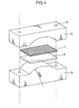
- FIG. 4 is a perspective view illustrating a jig to be used in the CBB test.
- the CBB test piece 6 is set between a pair of holder members 8 together with graphite fiber wool 7 for forming a crevice in the CBB test piece 6, and inserting two clamping bolts into respective ones of two holes 9 on opposite sides of the set of holder members 8 to clamp the CBB test piece 6 between the holder members 8 so as to allow the CBB test piece 6 to have a curvature.
- the holder members 8 comprise an upper holder member formed with a concave portion having a curvature radius of 100 mm, in a longitudinally central region thereof, and an upper holder member formed with a convex portion having a curvature radius of 100 mm, in an longitudinally central region thereof.
- the CBB test piece 6 attached to the jig was immersed into high-temperature/high pressure water in an autoclave (oxygen saturation concentration: 8 wt ppm, 70 kgf/cm 2 , 290°C) for 500 hours. After the immersion, the CBB test piece 6 was detached from the jig, and a cracking state was evaluated based on observation of a cross-section of the CBB test piece 6 by the following criteria.
- ⁇ The maximum crack depth is less than 15 ⁇ m, and the CBB test was passed.
- ⁇ The maximum crack depth is equal to or greater than 15 ⁇ m, and the CBB test was not passed.
- Each of the welding materials Nos. A to L was subjected to a Coriou corrosion test simulating an intergranular corrosion environment in a high-concentration nitric acid solution including a highly-acid metal ion, in the following manner.
- Each of the welding materials was immersed into 500 mL of 8N boiling nitric acid solution having 1.0 g/L of Cr 6+ ion added thereto. 4 batches of the immersion operations were performed while renewing the solution, wherein one batch was set to 24 hours. After completion of the 4 batches, the welding material was taken out of the solution, and a corrosion weight loss thereof was measured to evaluate a corrosion speed.
- Table 2 illustrates results of the CBB test and the Coriou test.
- the raw of "NON” in the “Welding Material NO” represents a test result on a test piece (comparative example) in which the overlay weld of the welding material 1 is eliminated from the weld joint test member 11.
- a stress corrosion cracking resistance and an intergranular corrosion resistance of the weld joint is significantly improved as compared with a weld joint devoid of the overlay weld on the heat-affected zone 5, even if an austenitic stainless steel member having a high C content as in SUS 304 is used as a base metal of piping constituting a weld, i.e., a base metal (plate members 2, 3) of the weld joint test member 11.
- the weld joint in which the heat-affected zone 5 is overlay-welded with the welding material according to the present invention exhibits excellent stress corrosion cracking resistance and intergranular corrosion resistance.
- the use of the welding material according to the present invention as the welding material 1 makes it possible to suppress intergranular corrosion in an overlay weld and sufficiently prevent stress corrosion cracking.
- the intergranular corrosion resistance is improved by setting the Ti content in the welding material to be equal to or greater than the total content of C, P, S, N and O in terms of Ti equivalent. This would be because, when the welding material No. H is used as the welding material 1, the above impurity elements causing intergranular corrosion are segregated in grain boundaries, whereas, when the welding material No.
- the impurity elements are precipitated in a deposited metal in the form of Ti-based carbides and other compounds, such as TiC, FeTiP, TiS, TiN and TiO 2 so as to allow the impurity elements to become harmless.
- an austenitic welding material which contains C: 0.01 wt% or less, Si: 0.5 wt% or less, Mn: 0.5 wt% or less, P: 0.005 wt% or less, S: 0.005 wt% or less, Ni: 15 to 40 wt%, Cr: 20 to 30 wt%, N: 0.01 wt% or less, O: 0.01 wt% or less, and the balance of Fe and inevitable impurities, wherein the content of B contained as one of the inevitable impurities in the welding material is 3 wt ppm or less, and the total content of C, P, S, N and O in the welding material is 0.02 wt% or less.
- the content of impurity elements segregated in grain boundaries to cause a decrease in grain boundary energy is low, and in particular the B content in the welding material is 3 wt ppm or less, so that it becomes possible to suppress intergranular corrosion in a weld metal formed by welding using the welding material (or a deposited metal formed by overlay welding), and sufficiently suppress stress corrosion cracking.
- the C content is 0.01 wt% or less, so that it becomes possible to suppress precipitation of Cr-based carbides.
- the Si content is 0.5 wt% or less, so that it becomes possible to suppress the intergranular corrosion.
- the Mn content is 0.5 wt% or less, so that it becomes possible to suppress corrosion due to formation of ⁇ -ferrite.
- the P content is 0.005 wt% or less, so that it becomes possible to suppress intergranular segregation of P so as to prevent deterioration in the intergranular corrosion resistance and stress corrosion cracking resistance.
- the S content is 0.005 wt% or less, so that it becomes possible to suppress formation of sulfides so as to prevent deterioration in the intergranular corrosion resistance and stress corrosion cracking resistance.
- the Ni content is 15 wt% or more, so that it becomes possible to allow the welding material and a metal structure of a weld metal formed by welding using the welding material (and a deposited metal firmed by overlay welding using the welding material) to be stabilized in austenite so as to suppress the intergranular corrosion and stress corrosion cracking. Further, the Ni content is 40 wt% or less, so that it becomes possible to facilitate a reduction in cost.
- the Cr content is 20 wt% or more, so that it becomes possible to ensure a sufficient corrosion resistance of a weld metal formed by welding using the welding material (and a deposited metal firmed by overlay welding using the welding material), for example, under a high-temperature/high-pressure underwater environment undergoing neutron irradiation, as in a core of a light-water nuclear reactor, and under a transpassive corrosion environment between a boiling heat transfer surface and a high-concentration nitric acid solution including a highly-acid ion, as in a reprocessing plant. Further, the Cr content is 30 wt% or less, so that it becomes possible to suppress precipitation of a Cr-rich brittle phase.
- Each of the N content and the O content is 0.01 wt% or less, and the sum of the C content, the P content, the S content, the N content and the O content is 0.02 wt% or less, so that it becomes possible to suppress a decrease in grain boundary energy due to segregation of these elements.
- a weld metal formed by welding using the welding material of the present invention (and a deposited metal firmed by overlay welding using the welding material) exhibits excellent intergranular corrosion resistance and stress corrosion cracking resistance.
- the welding material of the present invention is an austenitic welding material having a low content of impurity elements.
- a temperature rise of a base metal can be suppressed to a low level, so that it becomes possible to narrow a welding heat-affected zone, i.e., a sensitized zone.
- solidification of a weld will be promptly completed, and a residual stress in a weld is placed in a compressive state, so that a welded junction exhibits excellent intergranular corrosion resistance and stress corrosion cracking resistance, as well as the weld metal and the deposited metal.
- the welding material of the present invention can be used for welding of apparatus, piping or the like, for example, in a nuclear power plant, to effectively prevent the occurrence and development of stress corrosion cracking or the like in a weld metal and a welding heat-affected zone.
- a welded junction of the apparatus, piping or the like can be overlay-welded with the welding material of the present invention, to effectively prevent the occurrence and development of stress corrosion cracking or the like in a weld metal and a welding heat-affected zone.
- the welding material of the present invention further contains Ti, and wherein Ti, C, P, S, N and O contents in the welding material satisfy the aforementioned formula (1).
- impurity elements causing the intergranular corrosion such as C, P, S, N and O
- a deposited metal in the form of Ti-based carbides, Ti-based phosphides, Ti-based sulfides, Ti-based nitrides, Ti-based oxides and other Ti-based compounds, such as TiC, FeTiP, TiS, TiN and TiO 2 , to render the impurity elements harmless to the stress corrosion cracking and intergranular corrosion, particularly to the intergranular corrosion.
- a preventive maintenance method for stress corrosion cracking of a structure formed by welding austenitic stainless steel members together comprises an overlay welding step of overlay-welding the above welding material to a surface of a welding heat-affected zone of the structure to form an overlay weld thereon.
- preventive maintenance method of the present invention it becomes possible to effectively prevent the occurrence and development of stress corrosion cracking or the like in a heat-affected zone within a welded junction of a structure (e.g., welded junction of an austenitic stainless steel component or piping).
- the preventive maintenance method of the present invention further comprises a repair welding step of, before the overlay welding step, removing a defective portion existing in a welded junction and subjecting the removed portion to repair welding, and wherein the overlay welding in the overlay welding step is performed to allow the welded junction to be coated with the overlay weld.
- a preventive maintenance method for stress corrosion cracking of a structure formed by welding and joining at least a first austenitic stainless steel member and a second austenitic stainless steel member comprises the steps of: separating the second austenitic stainless steel member uses in the structure and to be replaced with a countermeasure member, from the first austenitic stainless steel member, and detaching the second austenitic stainless steel member from the structure; overlay-welding the above welding material to each of a groove surface of the countermeasure member and a groove surface of the first austenitic stainless steel member; and welding and joining the overlay-welded groove surface of the countermeasure member and the overlay-welded groove surface of the first austenitic stainless steel member.
- the welding material is overlay-welded to each of the groove surface of the countermeasure member and the groove surface of the first austenitic stainless steel member, so that it becomes possible to suppress sensitization in heat-affected zones of both of the countermeasure member and the first austenitic stainless steel member so as to effectively prevent the occurrence and development of stress corrosion cracking or the like.
- a preventive maintenance method for intergranular corrosion of an austenitic stainless steel structure contactable with a corrosive fluid comprises a step of overlay-welding the above welding material to a surface of the structure contactable with the corrosive fluid, to form an overlay weld thereon so as to prevent the contact with the corrosive fluid.
- the overlay weld keeps the corrosive fluid from coming into direct contact with a structure (e.g., welded junction of an austenitic stainless steel component or piping), so that it becomes possible to effectively prevent intergranular corrosion of the structure.
- a structure e.g., welded junction of an austenitic stainless steel component or piping
- the structure may be formed by welding austenitic stainless steel members together, wherein one of opposite surfaces of a welded junction of the structure is the surface contactable with the corrosive fluid.
- the overlay weld keeps the corrosive fluid from coming into direct contact with the welded junction, so that it becomes possible to effectively prevent intergranular corrosion of the welded junction.
- the austenitic welding material of the present invention is usable to improve a stress corrosion cracking resistance and an intergranular corrosion resistance in a weld metal and a heat-affected zone of the welded structure. More specifically, the austenitic welding material of the present invention is usable as a welding material for equipment, piping or the like, for example, in a nuclear power plant, to effectively prevent the occurrence and development of stress corrosion cracking or the like in a weld metal and a heat-affected zone. Further, the austenitic welding material of the present invention is usable in overlay welding for a welded junction of the welded structure, to further improve the stress corrosion cracking resistance and intergranular corrosion resistance in the weld metal and the heat-affected zone.
- the stress-corrosion-cracking preventive maintenance method of the present invention is applicable to a welded structure to prevent stress corrosion cracking of the welded structure more reliably than ever before.
- the intergranular-corrosion preventive maintenance method of the present invention is applicable to a welded structure to prevent intergranular corrosion of the welded structure more reliably than ever before.
Landscapes
- Engineering & Computer Science (AREA)
- Chemical & Material Sciences (AREA)
- Mechanical Engineering (AREA)
- Materials Engineering (AREA)
- Metallurgy (AREA)
- Organic Chemistry (AREA)
- Physics & Mathematics (AREA)
- Plasma & Fusion (AREA)
- Thermal Sciences (AREA)
- Crystallography & Structural Chemistry (AREA)
- General Engineering & Computer Science (AREA)
- Arc Welding In General (AREA)
- Butt Welding And Welding Of Specific Article (AREA)
Applications Claiming Priority (2)
| Application Number | Priority Date | Filing Date | Title |
|---|---|---|---|
| JP2008322639A JP5463527B2 (ja) | 2008-12-18 | 2008-12-18 | オーステナイト系ステンレス鋼からなる溶接材料およびそれを用いた応力腐食割れ予防保全方法ならびに粒界腐食予防保全方法 |
| PCT/JP2009/070965 WO2010071146A1 (fr) | 2008-12-18 | 2009-12-16 | Matériau de soudage à base d'austénite, procédé d'entretien préventif contre la corrosion fissurante sous tension et procédé d'entretien préventif contre la corrosion intercristalline utilisant ce dernier |
Publications (3)
| Publication Number | Publication Date |
|---|---|
| EP2422919A1 true EP2422919A1 (fr) | 2012-02-29 |
| EP2422919A4 EP2422919A4 (fr) | 2013-06-19 |
| EP2422919B1 EP2422919B1 (fr) | 2019-02-20 |
Family
ID=42268817
Family Applications (1)
| Application Number | Title | Priority Date | Filing Date |
|---|---|---|---|
| EP09833449.3A Not-in-force EP2422919B1 (fr) | 2008-12-18 | 2009-12-16 | Matériau de soudage à base d'austénite, procédé d'entretien préventif contre la corrosion fissurante sous tension et procédé d'entretien préventif contre la corrosion intercristalline utilisant ce dernier |
Country Status (7)
| Country | Link |
|---|---|
| US (1) | US8322592B2 (fr) |
| EP (1) | EP2422919B1 (fr) |
| JP (1) | JP5463527B2 (fr) |
| KR (1) | KR101305778B1 (fr) |
| CN (1) | CN102245345B (fr) |
| RU (1) | RU2488471C2 (fr) |
| WO (1) | WO2010071146A1 (fr) |
Families Citing this family (17)
| Publication number | Priority date | Publication date | Assignee | Title |
|---|---|---|---|---|
| ES2542743T3 (es) * | 2009-12-04 | 2015-08-11 | Nippon Steel & Sumitomo Metal Corporation | Estructura soldada con una junta soldada a tope y método para su fabricación |
| WO2012157542A1 (fr) * | 2011-05-13 | 2012-11-22 | 住友金属工業株式会社 | Matériau de soudage et raccord soudé |
| JP6016742B2 (ja) * | 2013-09-12 | 2016-10-26 | 三菱重工業株式会社 | 溶射膜又は肉盛溶接層の材料選定方法及び装置 |
| WO2015129631A1 (fr) * | 2014-02-26 | 2015-09-03 | 新日鐵住金株式会社 | Joint soudé |
| WO2016016717A1 (fr) * | 2014-07-31 | 2016-02-04 | Sabic Global Technologies B.V. | Réparation d'aciers inoxydables sigmatisés |
| WO2017142435A1 (fr) * | 2016-02-19 | 2017-08-24 | Общество С Ограниченной Ответственностью "Ромет" | Procédé de soudage d'un dispositif à partir de matériaux métalliques à couches multiples résistant à la corrosion |
| BR112018071995A2 (pt) * | 2016-05-02 | 2019-02-12 | Exxonmobil Research And Engineering Company | tecnologia de soldagem em circunferência no campo para dutos de aço com alto teor de manganês para pasta fluida |
| US9541485B1 (en) * | 2016-08-15 | 2017-01-10 | Kuwait Institute For Scientific Research | System for testing stress corrosion cracking |
| EP3574179B1 (fr) | 2017-01-30 | 2023-09-27 | National Oilwell Varco, L.P. | Tuyau soudé renforcé, connexions filetées et leurs procédés de réalisation |
| US10625361B2 (en) * | 2017-06-14 | 2020-04-21 | General Electric Company | Method of welding superalloys |
| JP7089246B2 (ja) * | 2018-06-27 | 2022-06-22 | Smc株式会社 | 鋼材の突合せ溶接継手及びその製造方法 |
| JP7082541B2 (ja) * | 2018-07-20 | 2022-06-08 | 三菱重工業株式会社 | 補修溶接方法 |
| KR20200101647A (ko) | 2019-02-20 | 2020-08-28 | 한양대학교 산학협력단 | 슈퍼 오스테나이트계 스테인레스강 |
| JP7570243B2 (ja) * | 2021-01-28 | 2024-10-21 | 日鉄ステンレス株式会社 | 尿素scrシステム用ステンレス鋼製溶接部材 |
| US12326203B2 (en) | 2023-06-30 | 2025-06-10 | Halliburton Energy Services, Inc. | Downhole tool with crack compliant seal and mechanical strengthening feature at a joint thereof |
| US12326046B2 (en) | 2023-06-30 | 2025-06-10 | Halliburton Energy Services, Inc. | Downhole tool with crack compliant seal and high yield strength weld positioned at a joint thereof |
| US20250242409A1 (en) * | 2024-01-26 | 2025-07-31 | Rtx Corporation | Use of sacrificial surface during directed energy deposition repair process |
Family Cites Families (51)
| Publication number | Priority date | Publication date | Assignee | Title |
|---|---|---|---|---|
| US3017266A (en) * | 1960-06-02 | 1962-01-16 | United Steel Companies Ltd | Austenitic steel and articles made therefrom |
| US3151978A (en) * | 1960-12-30 | 1964-10-06 | Armco Steel Corp | Heat hardenable chromium-nickel-aluminum steel |
| US3306736A (en) * | 1963-08-30 | 1967-02-28 | Crucible Steel Co America | Austenitic stainless steel |
| AT268345B (de) * | 1965-03-09 | 1969-02-10 | Schoeller Bleckmann Stahlwerke | Austenitischer, korrosionsbeständiger Chrom-Nickel-Mangan-Stickstoff-Stahl für die Herstellung von Gegenständen, die beständig gegen Lochfraß und Spannungsrißkorrosion in Meerwasser sind und Nichtmagnetisierbarkeit und gute Schweißbarkeit aufweisen |
| DE1558635B2 (de) * | 1966-02-10 | 1970-06-18 | Sumitomo Kinzoku Kogyo Kabushiki Kaisha, Osaka (Japan) | Hochfester stabilaustenitischer korrosionsbeständiger Stahl zur Herstellung von Verdampferrohren und Überhitzerrohren |
| AT295954B (de) * | 1969-07-11 | 1972-01-25 | Boehler & Co Ag Geb | Schweißmaterial zum elektrischen Lichtbogenschweißen von Gegenständen aus kaltzähem Stahl |
| US4049186A (en) * | 1976-10-20 | 1977-09-20 | General Electric Company | Process for reducing stress corrosion in a weld by applying an overlay weld |
| JPS5431062A (en) * | 1977-08-12 | 1979-03-07 | Hitachi Ltd | Manufacture of structure superior in stress corrosion cracking resistivity |
| JPS5921711B2 (ja) | 1978-07-11 | 1984-05-22 | 株式会社日立製作所 | ステンレス鋼材の溶接方法 |
| JPS56131083A (en) * | 1980-11-10 | 1981-10-14 | Hitachi Ltd | Welded joint method for stainless steel tube |
| DE3225266A1 (de) | 1982-07-06 | 1984-01-12 | Bayer Ag, 5090 Leverkusen | Kontinuierliches trockenspinnverfahren fuer acrylnitrilfaeden und - fasern |
| US4624402A (en) * | 1983-01-18 | 1986-11-25 | Nutech, Inc. | Method for applying an overlay weld for preventing and controlling stress corrosion cracking |
| JPS60100629A (ja) * | 1983-11-08 | 1985-06-04 | Sumitomo Metal Ind Ltd | オ−ステナイトステンレス鋼の製造方法 |
| JPS60152661A (ja) * | 1984-01-23 | 1985-08-10 | Daido Steel Co Ltd | 食品機器用含Biオーステナイト系ステンレス快削鋼 |
| JPS61177325A (ja) | 1985-01-31 | 1986-08-09 | Sumitomo Metal Ind Ltd | ステンレス鋼溶接部の耐食性改善方法 |
| JPH0647708B2 (ja) * | 1985-07-31 | 1994-06-22 | 大同特殊鋼株式会社 | オ−ステナイト系快削ステンレス鋼 |
| JPS6369947A (ja) | 1986-09-11 | 1988-03-30 | Kawasaki Steel Corp | クリ−プ破断延性の優れたオ−ステナイト系ステンレス鋼 |
| SE8904065L (sv) * | 1988-12-07 | 1990-06-08 | Hitachi Ltd | Metod att foerbaettra egenskaperna hos svetsare paa austenitiskt rostfritt staal |
| JP2865749B2 (ja) | 1988-12-07 | 1999-03-08 | 株式会社日立製作所 | 配管の改質方法 |
| JP2831051B2 (ja) * | 1989-09-22 | 1998-12-02 | 株式会社神戸製鋼所 | オーステナイト系ステンレス鋼溶接用ワイヤ |
| US4962586A (en) * | 1989-11-29 | 1990-10-16 | Westinghouse Electric Corp. | Method of making a high temperature - low temperature rotor for turbines |
| JP2530231B2 (ja) * | 1989-12-20 | 1996-09-04 | 日新製鋼株式会社 | 耐熱用オ―ステナイト系ステンレス鋼 |
| JPH0577082A (ja) | 1991-09-20 | 1993-03-30 | Hitachi Ltd | オーステナイト系ステンレス鋼の溶接部改質方法 |
| EP0727503B1 (fr) * | 1993-10-20 | 2001-09-26 | Sumitomo Metal Industries, Ltd. | Acier inoxydable pour gaz haute purete |
| JPH085773A (ja) | 1994-06-20 | 1996-01-12 | Toshiba Corp | ジェットポンプの予防保全装置と予防保全方法 |
| JPH0929429A (ja) | 1995-07-21 | 1997-02-04 | Toshiba Corp | 溶接施工方法 |
| US5809098A (en) * | 1997-03-10 | 1998-09-15 | General Electric Company | Method for sealing a stub tube in a nuclear reactor |
| JP2000254776A (ja) * | 1999-03-10 | 2000-09-19 | Toshiba Corp | 原子炉内部配管溶接部の応力腐食割れ防止方法 |
| JP2000312969A (ja) | 1999-04-30 | 2000-11-14 | Ishikawajima Harima Heavy Ind Co Ltd | 溶接継手部の外面バタリング工法 |
| JP2001107196A (ja) * | 1999-10-07 | 2001-04-17 | Sumitomo Metal Ind Ltd | 耐溶接割れ性と耐硫酸腐食性に優れたオーステナイト鋼溶接継手およびその溶接材料 |
| JP4465066B2 (ja) * | 1999-10-18 | 2010-05-19 | 日本冶金工業株式会社 | フェライト・オーステナイト二相系ステンレス鋼用溶接材料 |
| JP2001124888A (ja) * | 1999-10-26 | 2001-05-11 | Toshiba Corp | 応力腐食割れ予防保全方法 |
| JP2001138048A (ja) | 1999-11-08 | 2001-05-22 | Kobe Steel Ltd | 含Moオーステナイト系ステンレス鋼の肉盛溶接施工法 |
| KR100482208B1 (ko) * | 2000-11-17 | 2005-04-21 | 주식회사 포스코 | 침질처리에 의한 용접구조용 강재의 제조방법 |
| JP4490608B2 (ja) * | 2001-08-09 | 2010-06-30 | 株式会社東芝 | 構造物の補修方法 |
| KR100532877B1 (ko) * | 2002-04-17 | 2005-12-01 | 스미토모 긴조쿠 고교 가부시키가이샤 | 고온강도와 내식성이 우수한 오스테나이트계 스테인레스강및 상기 강으로부터 이루어지는 내열 내압부재와 그제조방법 |
| JP4424471B2 (ja) * | 2003-01-29 | 2010-03-03 | 住友金属工業株式会社 | オーステナイト系ステンレス鋼およびその製造方法 |
| JP4188124B2 (ja) * | 2003-03-31 | 2008-11-26 | 独立行政法人物質・材料研究機構 | 焼き戻しマルテンサイト系耐熱鋼の溶接継手 |
| JP3838216B2 (ja) * | 2003-04-25 | 2006-10-25 | 住友金属工業株式会社 | オーステナイト系ステンレス鋼 |
| BRPI0416001B1 (pt) * | 2003-10-31 | 2017-04-11 | Jfe Steel Corp | tubo de aço inoxidável sem costura para tubulações de condução |
| US6969826B2 (en) * | 2004-04-08 | 2005-11-29 | General Electric Company | Welding process |
| US7533795B2 (en) * | 2004-12-22 | 2009-05-19 | General Electric Company | Welding process |
| JP4273339B2 (ja) * | 2004-12-27 | 2009-06-03 | 住友金属工業株式会社 | 高Cr鋼の溶接継手および溶接材料 |
| WO2006104023A1 (fr) * | 2005-03-25 | 2006-10-05 | Sumitomo Metal Industries, Ltd. | Arbre d’entrainement creux obtenu via un durcissement par induction |
| WO2006106944A1 (fr) * | 2005-04-04 | 2006-10-12 | Sumitomo Metal Industries, Ltd. | Acier inoxydable austenitique |
| US8710405B2 (en) * | 2005-04-15 | 2014-04-29 | Nippon Steel & Sumikin Stainless Steel Corporation | Austenitic stainless steel welding wire and welding structure |
| US8980167B2 (en) * | 2005-04-28 | 2015-03-17 | Jfe Steel Corporation | Stainless steel pipe having excellent expandability for oil country tubular goods |
| US20080240970A1 (en) * | 2007-03-31 | 2008-10-02 | Daido Tokushuko Kabushiki Kaisha | Austenitic free-cutting stainless steel |
| CN101668873B (zh) * | 2007-04-27 | 2012-11-28 | 株式会社神户制钢所 | 耐晶界腐蚀性和耐应力腐蚀性优异的奥氏体系不锈钢以及奥氏体系不锈钢钢材的制造方法 |
| KR20090066000A (ko) * | 2007-12-18 | 2009-06-23 | 주식회사 포스코 | 고진공, 고순도 가스 배관용 오스테나이트계 스테인리스강 |
| US8319148B2 (en) * | 2009-08-20 | 2012-11-27 | General Electric Company | System and method of dual laser beam welding of first and second filler metals |
-
2008
- 2008-12-18 JP JP2008322639A patent/JP5463527B2/ja not_active Expired - Fee Related
-
2009
- 2009-12-16 EP EP09833449.3A patent/EP2422919B1/fr not_active Not-in-force
- 2009-12-16 RU RU2011129636/02A patent/RU2488471C2/ru active
- 2009-12-16 WO PCT/JP2009/070965 patent/WO2010071146A1/fr not_active Ceased
- 2009-12-16 CN CN200980150398.4A patent/CN102245345B/zh not_active Expired - Fee Related
- 2009-12-16 KR KR1020117016457A patent/KR101305778B1/ko not_active Expired - Fee Related
- 2009-12-16 US US13/140,674 patent/US8322592B2/en not_active Expired - Fee Related
Also Published As
| Publication number | Publication date |
|---|---|
| KR101305778B1 (ko) | 2013-09-06 |
| JP5463527B2 (ja) | 2014-04-09 |
| RU2011129636A (ru) | 2013-01-27 |
| US8322592B2 (en) | 2012-12-04 |
| EP2422919A4 (fr) | 2013-06-19 |
| WO2010071146A1 (fr) | 2010-06-24 |
| RU2488471C2 (ru) | 2013-07-27 |
| JP2010142843A (ja) | 2010-07-01 |
| US20110248071A1 (en) | 2011-10-13 |
| KR20110098822A (ko) | 2011-09-01 |
| CN102245345A (zh) | 2011-11-16 |
| EP2422919B1 (fr) | 2019-02-20 |
| CN102245345B (zh) | 2015-09-02 |
Similar Documents
| Publication | Publication Date | Title |
|---|---|---|
| EP2422919B1 (fr) | Matériau de soudage à base d'austénite, procédé d'entretien préventif contre la corrosion fissurante sous tension et procédé d'entretien préventif contre la corrosion intercristalline utilisant ce dernier | |
| US20230203632A1 (en) | Austenitic stainless steel weld joint | |
| Kuo et al. | Effects of filler metal composition on joining properties of alloy 690 weldments | |
| Brooks et al. | Selection of wrought austenitic stainless steels | |
| EP3693484A1 (fr) | Métal soudé d'acier inoxydable à base d'austénite, et structure soudée | |
| KR20240144320A (ko) | 니켈-크롬-알루미늄 합금으로 만들어진 용접 이음매들을 구비한 부품의 제조 방법 | |
| Najafi et al. | Microstructure and phase analysis of multilayer Ni–Cr–Mo clad for corrosion protection | |
| JP2005023343A (ja) | 原子力用オーステナイト系ステンレス鋼管 | |
| Kain et al. | Controlling corrosion in the back end of fuel cycle using nitric acid grade stainless steels | |
| JP4196755B2 (ja) | 低炭素ステンレス鋼管の配管溶接継手とその製造方法 | |
| JP2000254776A (ja) | 原子炉内部配管溶接部の応力腐食割れ防止方法 | |
| JP4273339B2 (ja) | 高Cr鋼の溶接継手および溶接材料 | |
| JPH0195895A (ja) | ステンレス鋼ガスシールドアーク溶接用ワイヤ | |
| JP7140207B2 (ja) | フェライト系耐熱鋼溶接継手の製造方法 | |
| JP4026554B2 (ja) | 低炭素ステンレス鋼管の配管溶接継手とその製造方法 | |
| JP7011987B2 (ja) | Ni基溶接金属及び溶接構造物 | |
| Jha et al. | Metallographic analysis of embedded crack in electron beam welded austenitic stainless steel chemical storage tank | |
| US10550451B2 (en) | Ni-based alloy pipe or tube for nuclear power | |
| JPH02258190A (ja) | 配管の改質方法 | |
| Dove et al. | An austenitic stainless steel, resistant to high temperature creep and naphthenic acids attack in refinery environments | |
| Li et al. | Study of modified 9Cr-1Mo welds | |
| JP2006159262A (ja) | 溶接継手および溶接材料 | |
| JP2622516B2 (ja) | クリープ強度の優れた耐熱鋼用溶接材料 | |
| JPS61126972A (ja) | 肉盛溶接部の割れ防止方法 | |
| Lancaster | Austenitic and high-alloy steels |
Legal Events
| Date | Code | Title | Description |
|---|---|---|---|
| PUAI | Public reference made under article 153(3) epc to a published international application that has entered the european phase |
Free format text: ORIGINAL CODE: 0009012 |
|
| 17P | Request for examination filed |
Effective date: 20110628 |
|
| AK | Designated contracting states |
Kind code of ref document: A1 Designated state(s): AT BE BG CH CY CZ DE DK EE ES FI FR GB GR HR HU IE IS IT LI LT LU LV MC MK MT NL NO PL PT RO SE SI SK SM TR |
|
| DAX | Request for extension of the european patent (deleted) | ||
| A4 | Supplementary search report drawn up and despatched |
Effective date: 20130523 |
|
| RIC1 | Information provided on ipc code assigned before grant |
Ipc: B23K 9/23 20060101ALI20130516BHEP Ipc: B23K 103/04 20060101ALI20130516BHEP Ipc: B23K 31/00 20060101ALI20130516BHEP Ipc: B23K 9/04 20060101ALI20130516BHEP Ipc: B23K 35/30 20060101AFI20130516BHEP Ipc: B23K 9/00 20060101ALI20130516BHEP |
|
| STAA | Information on the status of an ep patent application or granted ep patent |
Free format text: STATUS: EXAMINATION IS IN PROGRESS |
|
| 17Q | First examination report despatched |
Effective date: 20171106 |
|
| GRAP | Despatch of communication of intention to grant a patent |
Free format text: ORIGINAL CODE: EPIDOSNIGR1 |
|
| STAA | Information on the status of an ep patent application or granted ep patent |
Free format text: STATUS: GRANT OF PATENT IS INTENDED |
|
| RIC1 | Information provided on ipc code assigned before grant |
Ipc: B23K 31/12 20060101ALI20180621BHEP Ipc: B23K 35/30 20060101AFI20180621BHEP Ipc: B23K 103/04 20060101ALI20180621BHEP Ipc: C22C 38/54 20060101ALI20180621BHEP Ipc: C22C 38/02 20060101ALI20180621BHEP Ipc: C22C 38/00 20060101ALI20180621BHEP Ipc: C22C 38/50 20060101ALI20180621BHEP Ipc: C21D 9/50 20060101ALI20180621BHEP Ipc: B23K 9/04 20060101ALI20180621BHEP Ipc: F16J 12/00 20060101ALI20180621BHEP Ipc: B23K 9/00 20060101ALI20180621BHEP Ipc: B23K 9/23 20060101ALI20180621BHEP Ipc: B23K 31/00 20060101ALI20180621BHEP Ipc: C22C 38/04 20060101ALI20180621BHEP |
|
| INTG | Intention to grant announced |
Effective date: 20180712 |
|
| GRAS | Grant fee paid |
Free format text: ORIGINAL CODE: EPIDOSNIGR3 |
|
| RAP1 | Party data changed (applicant data changed or rights of an application transferred) |
Owner name: KABUSHIKI KAISHA KOBE SEIKO SHO |
|
| RIN1 | Information on inventor provided before grant (corrected) |
Inventor name: MARUYAMA, NOBUTOSHI Inventor name: KIUCHI, KIYOSHI Inventor name: TSUKATANI, ICHIRO Inventor name: IOKA, IKUO Inventor name: TANABE, MAKOTO Inventor name: NAKAYAMA, JUMPEI Inventor name: KATO, CHIAKI |
|
| GRAA | (expected) grant |
Free format text: ORIGINAL CODE: 0009210 |
|
| STAA | Information on the status of an ep patent application or granted ep patent |
Free format text: STATUS: THE PATENT HAS BEEN GRANTED |
|
| AK | Designated contracting states |
Kind code of ref document: B1 Designated state(s): AT BE BG CH CY CZ DE DK EE ES FI FR GB GR HR HU IE IS IT LI LT LU LV MC MK MT NL NO PL PT RO SE SI SK SM TR |
|
| REG | Reference to a national code |
Ref country code: GB Ref legal event code: FG4D |
|
| REG | Reference to a national code |
Ref country code: CH Ref legal event code: EP |
|
| REG | Reference to a national code |
Ref country code: DE Ref legal event code: R096 Ref document number: 602009057119 Country of ref document: DE |
|
| REG | Reference to a national code |
Ref country code: AT Ref legal event code: REF Ref document number: 1097552 Country of ref document: AT Kind code of ref document: T Effective date: 20190315 |
|
| REG | Reference to a national code |
Ref country code: IE Ref legal event code: FG4D |
|
| REG | Reference to a national code |
Ref country code: LT Ref legal event code: MG4D |
|
| REG | Reference to a national code |
Ref country code: NL Ref legal event code: MP Effective date: 20190220 |
|
| PG25 | Lapsed in a contracting state [announced via postgrant information from national office to epo] |
Ref country code: SE Free format text: LAPSE BECAUSE OF FAILURE TO SUBMIT A TRANSLATION OF THE DESCRIPTION OR TO PAY THE FEE WITHIN THE PRESCRIBED TIME-LIMIT Effective date: 20190220 Ref country code: LT Free format text: LAPSE BECAUSE OF FAILURE TO SUBMIT A TRANSLATION OF THE DESCRIPTION OR TO PAY THE FEE WITHIN THE PRESCRIBED TIME-LIMIT Effective date: 20190220 Ref country code: FI Free format text: LAPSE BECAUSE OF FAILURE TO SUBMIT A TRANSLATION OF THE DESCRIPTION OR TO PAY THE FEE WITHIN THE PRESCRIBED TIME-LIMIT Effective date: 20190220 Ref country code: NO Free format text: LAPSE BECAUSE OF FAILURE TO SUBMIT A TRANSLATION OF THE DESCRIPTION OR TO PAY THE FEE WITHIN THE PRESCRIBED TIME-LIMIT Effective date: 20190520 Ref country code: PT Free format text: LAPSE BECAUSE OF FAILURE TO SUBMIT A TRANSLATION OF THE DESCRIPTION OR TO PAY THE FEE WITHIN THE PRESCRIBED TIME-LIMIT Effective date: 20190620 |
|
| PG25 | Lapsed in a contracting state [announced via postgrant information from national office to epo] |
Ref country code: IS Free format text: LAPSE BECAUSE OF FAILURE TO SUBMIT A TRANSLATION OF THE DESCRIPTION OR TO PAY THE FEE WITHIN THE PRESCRIBED TIME-LIMIT Effective date: 20190620 Ref country code: GR Free format text: LAPSE BECAUSE OF FAILURE TO SUBMIT A TRANSLATION OF THE DESCRIPTION OR TO PAY THE FEE WITHIN THE PRESCRIBED TIME-LIMIT Effective date: 20190521 Ref country code: BG Free format text: LAPSE BECAUSE OF FAILURE TO SUBMIT A TRANSLATION OF THE DESCRIPTION OR TO PAY THE FEE WITHIN THE PRESCRIBED TIME-LIMIT Effective date: 20190520 Ref country code: NL Free format text: LAPSE BECAUSE OF FAILURE TO SUBMIT A TRANSLATION OF THE DESCRIPTION OR TO PAY THE FEE WITHIN THE PRESCRIBED TIME-LIMIT Effective date: 20190220 Ref country code: LV Free format text: LAPSE BECAUSE OF FAILURE TO SUBMIT A TRANSLATION OF THE DESCRIPTION OR TO PAY THE FEE WITHIN THE PRESCRIBED TIME-LIMIT Effective date: 20190220 Ref country code: HR Free format text: LAPSE BECAUSE OF FAILURE TO SUBMIT A TRANSLATION OF THE DESCRIPTION OR TO PAY THE FEE WITHIN THE PRESCRIBED TIME-LIMIT Effective date: 20190220 |
|
| REG | Reference to a national code |
Ref country code: AT Ref legal event code: MK05 Ref document number: 1097552 Country of ref document: AT Kind code of ref document: T Effective date: 20190220 |
|
| PG25 | Lapsed in a contracting state [announced via postgrant information from national office to epo] |
Ref country code: CZ Free format text: LAPSE BECAUSE OF FAILURE TO SUBMIT A TRANSLATION OF THE DESCRIPTION OR TO PAY THE FEE WITHIN THE PRESCRIBED TIME-LIMIT Effective date: 20190220 Ref country code: RO Free format text: LAPSE BECAUSE OF FAILURE TO SUBMIT A TRANSLATION OF THE DESCRIPTION OR TO PAY THE FEE WITHIN THE PRESCRIBED TIME-LIMIT Effective date: 20190220 Ref country code: SK Free format text: LAPSE BECAUSE OF FAILURE TO SUBMIT A TRANSLATION OF THE DESCRIPTION OR TO PAY THE FEE WITHIN THE PRESCRIBED TIME-LIMIT Effective date: 20190220 Ref country code: ES Free format text: LAPSE BECAUSE OF FAILURE TO SUBMIT A TRANSLATION OF THE DESCRIPTION OR TO PAY THE FEE WITHIN THE PRESCRIBED TIME-LIMIT Effective date: 20190220 Ref country code: EE Free format text: LAPSE BECAUSE OF FAILURE TO SUBMIT A TRANSLATION OF THE DESCRIPTION OR TO PAY THE FEE WITHIN THE PRESCRIBED TIME-LIMIT Effective date: 20190220 Ref country code: DK Free format text: LAPSE BECAUSE OF FAILURE TO SUBMIT A TRANSLATION OF THE DESCRIPTION OR TO PAY THE FEE WITHIN THE PRESCRIBED TIME-LIMIT Effective date: 20190220 Ref country code: IT Free format text: LAPSE BECAUSE OF FAILURE TO SUBMIT A TRANSLATION OF THE DESCRIPTION OR TO PAY THE FEE WITHIN THE PRESCRIBED TIME-LIMIT Effective date: 20190220 |
|
| REG | Reference to a national code |
Ref country code: DE Ref legal event code: R097 Ref document number: 602009057119 Country of ref document: DE |
|
| PG25 | Lapsed in a contracting state [announced via postgrant information from national office to epo] |
Ref country code: SM Free format text: LAPSE BECAUSE OF FAILURE TO SUBMIT A TRANSLATION OF THE DESCRIPTION OR TO PAY THE FEE WITHIN THE PRESCRIBED TIME-LIMIT Effective date: 20190220 Ref country code: PL Free format text: LAPSE BECAUSE OF FAILURE TO SUBMIT A TRANSLATION OF THE DESCRIPTION OR TO PAY THE FEE WITHIN THE PRESCRIBED TIME-LIMIT Effective date: 20190220 |
|
| PLBE | No opposition filed within time limit |
Free format text: ORIGINAL CODE: 0009261 |
|
| STAA | Information on the status of an ep patent application or granted ep patent |
Free format text: STATUS: NO OPPOSITION FILED WITHIN TIME LIMIT |
|
| PG25 | Lapsed in a contracting state [announced via postgrant information from national office to epo] |
Ref country code: AT Free format text: LAPSE BECAUSE OF FAILURE TO SUBMIT A TRANSLATION OF THE DESCRIPTION OR TO PAY THE FEE WITHIN THE PRESCRIBED TIME-LIMIT Effective date: 20190220 |
|
| 26N | No opposition filed |
Effective date: 20191121 |
|
| PG25 | Lapsed in a contracting state [announced via postgrant information from national office to epo] |
Ref country code: SI Free format text: LAPSE BECAUSE OF FAILURE TO SUBMIT A TRANSLATION OF THE DESCRIPTION OR TO PAY THE FEE WITHIN THE PRESCRIBED TIME-LIMIT Effective date: 20190220 |
|
| PG25 | Lapsed in a contracting state [announced via postgrant information from national office to epo] |
Ref country code: TR Free format text: LAPSE BECAUSE OF FAILURE TO SUBMIT A TRANSLATION OF THE DESCRIPTION OR TO PAY THE FEE WITHIN THE PRESCRIBED TIME-LIMIT Effective date: 20190220 |
|
| REG | Reference to a national code |
Ref country code: DE Ref legal event code: R119 Ref document number: 602009057119 Country of ref document: DE |
|
| REG | Reference to a national code |
Ref country code: CH Ref legal event code: PL |
|
| REG | Reference to a national code |
Ref country code: BE Ref legal event code: MM Effective date: 20191231 |
|
| PG25 | Lapsed in a contracting state [announced via postgrant information from national office to epo] |
Ref country code: MC Free format text: LAPSE BECAUSE OF FAILURE TO SUBMIT A TRANSLATION OF THE DESCRIPTION OR TO PAY THE FEE WITHIN THE PRESCRIBED TIME-LIMIT Effective date: 20190220 |
|
| PG25 | Lapsed in a contracting state [announced via postgrant information from national office to epo] |
Ref country code: LU Free format text: LAPSE BECAUSE OF NON-PAYMENT OF DUE FEES Effective date: 20191216 Ref country code: IE Free format text: LAPSE BECAUSE OF NON-PAYMENT OF DUE FEES Effective date: 20191216 Ref country code: DE Free format text: LAPSE BECAUSE OF NON-PAYMENT OF DUE FEES Effective date: 20200701 |
|
| PG25 | Lapsed in a contracting state [announced via postgrant information from national office to epo] |
Ref country code: CH Free format text: LAPSE BECAUSE OF NON-PAYMENT OF DUE FEES Effective date: 20191231 Ref country code: LI Free format text: LAPSE BECAUSE OF NON-PAYMENT OF DUE FEES Effective date: 20191231 Ref country code: BE Free format text: LAPSE BECAUSE OF NON-PAYMENT OF DUE FEES Effective date: 20191231 |
|
| PG25 | Lapsed in a contracting state [announced via postgrant information from national office to epo] |
Ref country code: CY Free format text: LAPSE BECAUSE OF FAILURE TO SUBMIT A TRANSLATION OF THE DESCRIPTION OR TO PAY THE FEE WITHIN THE PRESCRIBED TIME-LIMIT Effective date: 20190220 |
|
| PG25 | Lapsed in a contracting state [announced via postgrant information from national office to epo] |
Ref country code: HU Free format text: LAPSE BECAUSE OF FAILURE TO SUBMIT A TRANSLATION OF THE DESCRIPTION OR TO PAY THE FEE WITHIN THE PRESCRIBED TIME-LIMIT; INVALID AB INITIO Effective date: 20091216 Ref country code: MT Free format text: LAPSE BECAUSE OF FAILURE TO SUBMIT A TRANSLATION OF THE DESCRIPTION OR TO PAY THE FEE WITHIN THE PRESCRIBED TIME-LIMIT Effective date: 20190220 |
|
| PG25 | Lapsed in a contracting state [announced via postgrant information from national office to epo] |
Ref country code: MK Free format text: LAPSE BECAUSE OF FAILURE TO SUBMIT A TRANSLATION OF THE DESCRIPTION OR TO PAY THE FEE WITHIN THE PRESCRIBED TIME-LIMIT Effective date: 20190220 |
|
| P01 | Opt-out of the competence of the unified patent court (upc) registered |
Effective date: 20230523 |
|
| PGFP | Annual fee paid to national office [announced via postgrant information from national office to epo] |
Ref country code: GB Payment date: 20231026 Year of fee payment: 15 |
|
| PGFP | Annual fee paid to national office [announced via postgrant information from national office to epo] |
Ref country code: FR Payment date: 20231009 Year of fee payment: 15 |
|
| GBPC | Gb: european patent ceased through non-payment of renewal fee |
Effective date: 20241216 |
|
| PG25 | Lapsed in a contracting state [announced via postgrant information from national office to epo] |
Ref country code: GB Free format text: LAPSE BECAUSE OF NON-PAYMENT OF DUE FEES Effective date: 20241216 |
|
| PG25 | Lapsed in a contracting state [announced via postgrant information from national office to epo] |
Ref country code: FR Free format text: LAPSE BECAUSE OF NON-PAYMENT OF DUE FEES Effective date: 20241231 |