EP2425313B1 - Improvements in or relating to cooling - Google Patents
Improvements in or relating to cooling Download PDFInfo
- Publication number
- EP2425313B1 EP2425313B1 EP10770283.9A EP10770283A EP2425313B1 EP 2425313 B1 EP2425313 B1 EP 2425313B1 EP 10770283 A EP10770283 A EP 10770283A EP 2425313 B1 EP2425313 B1 EP 2425313B1
- Authority
- EP
- European Patent Office
- Prior art keywords
- equipment
- air
- enclosure
- heat
- outside
- Prior art date
- Legal status (The legal status is an assumption and is not a legal conclusion. Google has not performed a legal analysis and makes no representation as to the accuracy of the status listed.)
- Active
Links
Images


Classifications
-
- H—ELECTRICITY
- H05—ELECTRIC TECHNIQUES NOT OTHERWISE PROVIDED FOR
- H05K—PRINTED CIRCUITS; CASINGS OR CONSTRUCTIONAL DETAILS OF ELECTRIC APPARATUS; MANUFACTURE OF ASSEMBLAGES OF ELECTRICAL COMPONENTS
- H05K7/00—Constructional details common to different types of electric apparatus
- H05K7/20—Modifications to facilitate cooling, ventilating, or heating
- H05K7/20709—Modifications to facilitate cooling, ventilating, or heating for server racks or cabinets; for data centers, e.g. 19-inch computer racks
- H05K7/208—Liquid cooling with phase change
- H05K7/20818—Liquid cooling with phase change within cabinets for removing heat from server blades
-
- H—ELECTRICITY
- H05—ELECTRIC TECHNIQUES NOT OTHERWISE PROVIDED FOR
- H05K—PRINTED CIRCUITS; CASINGS OR CONSTRUCTIONAL DETAILS OF ELECTRIC APPARATUS; MANUFACTURE OF ASSEMBLAGES OF ELECTRICAL COMPONENTS
- H05K7/00—Constructional details common to different types of electric apparatus
- H05K7/20—Modifications to facilitate cooling, ventilating, or heating
- H05K7/20709—Modifications to facilitate cooling, ventilating, or heating for server racks or cabinets; for data centers, e.g. 19-inch computer racks
- H05K7/208—Liquid cooling with phase change
- H05K7/20827—Liquid cooling with phase change within rooms for removing heat from cabinets, e.g. air conditioning devices
Definitions
- Data centers typically house high concentrations and densities of such computer systems and additionally provide facilities such as uninterruptible power supplies and cooling systems necessary for the operation of the computer systems in the data center.
- Computer systems inherently generate heat during operation.
- Typical heat generating sources in a computer system include central processing units (CPUs), graphics cards, mechanical storage drives, power supplies, and the like. This heat needs to be managed such that the maximum operating temperature of the various components of each computer system is not exceeded.
- Individual computer systems such as servers, typically use heat sinks to remove heat from heat generating sources. The heat is then evacuated outside the computer system housing by one or more internal mechanical fans which draw in cooler air from outside the computer system housing and exhaust warmed air through an exhaust vent.
- Typical computer systems are designed to draw air in through a vent on the front of the system and to exhaust warmed air through a vent in the rear of the system.
- equipment enclosures When arranged in data centers, computer equipment is generally installed in a frame or enclosure, such as a server enclosure rack, a rackable cabinet, or a server rack.
- An equipment enclosure may house multiple items of computer equipment.
- the depth of the equipment enclosure is chosen to have the approximately the same depth as the computer equipment installed therein.
- the rear panels of equipment enclosures are generally either not present, or are perforated to enable suitable ventilation of the installed computer equipment. In this way, air from outside the equipment enclosure is drawn into the computer equipment through a computer equipment front inlet vent, and is exhausted out of the computer equipment through a computer equipment rear exhaust vent. In such an arrangement, outside air heated by the computer equipment does not enter the equipment enclosure.
- Data centers also generally use computer room air conditioning units that supply cooled air to the front of the equipment enclosures and evacuate heated air from the back of the equipment enclosures to enhance cooling of the computer equipment.
- WO2008004280 discloses an enclosure in which a plurality of heat generating sources are thermally coupled to a heat exchanger.
- the enclosure includes an inlet on a side wall near the heat exchanger and an outlet on an upper surface of the enclosure above the heat exchanger.
- US20040037045 discloses a thermal management system for an electronic device including a first thermal energy transfer assembly that is thermally coupled between a heat generating structure located on a circuit card and a first thermal interface surface that is spaced away from the heat generating structure.
- a second thermal energy transfer assembly includes a second thermal interface surface which is arranged in confronting relation to the first thermal interface surface.
- US 7457118 discloses a heat dissipation apparatus includes a heat absorption device coupled to a board, the heat absorption device configured to absorb heat generated by an electrical device mounted on the board, a heat dispersion device configured discretely from the heat absorbing device and the board for dispersing heat input thereto and a heat transporting device coupled between the heat absorption device and the heat dispersion device for transporting heat absorbed by the heat absorption device to the heat dispersion device.
- US2008180903 relates to a computer system including a chassis defining a front and a rear.
- the chassis includes a vertically oriented midplane disposed therein, the midplane including a plurality of front module slots for receiving front electronic modules from the front of the chassis, and a plurality of rear module slots for receiving rear electronic modules from the rear of the chassis.
- a cooling system is provided within the chassis and generates an upwardly-directed front air flow within the chassis directed at selected ones of the front electronic modules and an upwardly-directed rear air flow within the chassis directed at selected ones of the rear electronic modules.
- the front air flow is separate from and independent of the rear air flow.
- the selected front and rear electronic modules are disposed in the chassis so as to separate the front air flow into a plurality of substantially equal front air streams and the rear air flow into a plurality of substantially equal rear air streams, respectively.
- US2007064391 relates to an electronic equipment enclosure comprising a frame structure formed from a plurality of support posts and at least partially enclosed by a plurality of panels.
- the panels include at least side, top and back panels defining an enclosure having a top, a bottom and a rear thereof.
- the top panel includes an opening there through that is rectangular in shape.
- the equipment enclosure further comprises an exhaust air duct extending upward from the top panel of the enclosure.
- the exhaust air duct is rectangular in cross-section and is disposed in surrounding relation to, and in fluid communication with, the top panel opening.
- the exhaust air duct is adapted to segregate hot air being exhausted from the enclosure from cool air entering the enclosure.
- US2007213000 relates to a system including a substantially sealed, substantially airtight cabinet sized for housing a vertical array of heat-producing units, the cabinet having an exterior shell and the system including an interior divider wall disposed inside the cabinet, the shell and divider wall providing an equipment chamber adapted to support the array such that the array cooperates with the shell and divider wall in use to define a first plenum, the first plenum having a first inlet defined by the divider wall for receiving a flow of cooling gas and having a first outlet defined by a plurality of openings through the array whereby the first plenum communicates with the openings in use to exhaust substantially all of the flow of cooling fluid through the openings and hence through the array, wherein the divider wall is configured to allow the first inlet to admit the gas to the first plenum in a substantially horizontal direction.
- JPH0697338A describes an electronic circuit casing constituted in such a way that it has an L-shaped cross section.
- a cooling casing for cooling a liquid refrigerant is connected and fitted to this L-shaped electronic circuit casing by means of couplings, whereby the entire casings are assembled into a rectangular-parallelopiped single unit.
- US 2007/274043 describes hybrid-cooled electronics chassis and boards. Such boards may be plugged in a chassis and connected to a common liquid-cooling loop shared by two or more of the boards inside that chassis. Liquid cooling conduits between the electronics board/module and the chassis are engaged and disengaged with little or no manual intervention.
- a chassis includes a base portion that has a fan, liquid cooling system and heat exchanger mounted thereon.
- An electronics module is selectively engageable with the base portion in a manner to have air displaced across the electronics module when engaged as well establish liquid flow through the electronics module when engaged.
- One aspect of the present invention provides an equipment enclosure according to claim 1. Another aspect of the present invention provides a facility according to claim 5. Another aspect of the present invention provides a data center according to claim 10. Further features are provided by the dependent claims.
- FIG. 1a and 1b there is shown a simplified section view of an equipment enclosure 102a according to a first illustrative example, and an equipment enclosure 102b according to a second illustrative example.
- the equipment enclosures 102a and 102b each comprise a substantially closed enclosure, with notably no exhaust vents in the rear of the equipment enclosure.
- the equipment enclosures also comprise a number of rails or other mounting means in which a number of a number of equipment enclosure-mountable computer equipment elements 104a, 104b, 104c, and 104d may be mounted or installed.
- the computer equipment may be, for example, computer servers, with each piece of equipment comprising one or more electronic heat generating sources, such as central processing units, graphics cards, DVD drives, power supplies, and the like.
- heat generating sources of the computer equipment 104a and 104b are thermally coupled to a heat pipe 103.
- heat generating sources may be thermally coupled directly to the heat pipe, or indirectly through separate heat pipes, thermosiphons, or in any other appropriate manner.
- the heat pipe 103 is additionally thermally coupled to a heat exchanger 108a housed within the equipment enclosure 102a.
- thermosiphon 106 At least some of the heat generating sources of the computer equipment 104c and 104d are thermally coupled to a thermosiphon 106.
- heat generating sources may be thermally coupled directly to the thermosiphon 106, or indirectly through separate heat pipes, thermosiphons, or in any other appropriate manner.
- the thermosiphon 106 is additionally thermally coupled to a heat exchanger 108b housed within the equipment enclosure 102b.
- the heat pipe 103 and thermosiphon 106 transfer heat from the heat sources to which they are thermally coupled to their respective heat exchangers. This prevents a build up of excess heat in the computer equipment 104a, 104b, 104c, and 104d, enabling the computer equipment to operate within its predetermined temperature operation range.
- the heat exchangers 108a and 108b are suitable for being air cooled, such as a tubed and finned heat exchanger, or the like.
- the precise type and technical characteristics of the heat exchanger may be determined by taking into account various parameters including, for example, the maximum outside air temperature, maximum operating temperature of the computer equipment, density of computer equipment, and the altitude of the data center.
- the air 110a and 110b in contact with the heat exchangers rises and is exhausted through exhaust vents 112 located in the top of the equipment enclosure housings. This action draws in cooler air from outside the equipment enclosures through inlet vents 114 located in the front side of the equipment enclosure housing.
- Adequate space is provided within the equipment enclosure to house the heat pipe and to enable sufficient air circulation from the inlet vents 114 to the exhaust vents 112 to cool the heat exchanger 108.
- space is left between the rear of the computer equipment and the rear of the equipment enclosure to enable the heat exchanger to be cooled by natural stack effect ventilation.
- alternative space arrangements may be used.
- the computer equipment 104a, 104b, 104c, and 104d does not require the use of internal mechanical fans to cool the heat generating sources. This leads to improved energy savings and a consequent reduction in operating costs. Since no fans are needed, the computer equipment 104a, 104b, 104c, and 104d also do not require traditional inlet and outlet vents, since the heat is effectively removed by the heat pipe 103 or thermosiphon 106. In this case, outside air drawn in through inlet vents 114 does not need to circulate within the computer equipment 104a and 104b, enabling the computer equipment housings to be substantially closed to the outside air.
- FIG. 2a shows an equipment enclosure 200 arrangement according to a further illustrative example.
- the equipment enclosure 200 houses computer equipment 201a and 201b each having an inlet vent 202 located at the front of the computer equipment, and an exhaust vent 204 located at the rear of the computer equipment.
- the equipment enclosure 200 is arranged such that outside air may only be drawn into the equipment enclosure 200 through the inlet vents 202 and the outlet vents 204 of the computer equipment 201a and 201b. This may be achieved, for example, by using blanking plates or brushes on any empty equipment enclosure placements, or by mounting the computer equipment in such a way that substantially no space is left vertically between different computer equipment elements. In this way, the stack effect ventilation responsible for cooling the heat exchanger 108 additionally helps remove any residual heat in the computer equipment 201a and 201b not removed by the heat pipe 103. In the illustrative example of Fig. 2a , which is not in accordance with the present invention, a single air path is used for cooling both the computer equipment 201 and the heat exchanger 108.
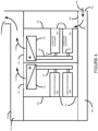
- FIG 2b shows an example according to the present invention.
- the example is similar to that shown in Figure 2a , but the equipment enclosure 220 has an additional inlet vent 224 through which outside air is drawn, by stack effect ventilation, to directly cool the heat exchanger 108.
- the equipment enclosure also has an internal baffle 222 which segregates the air drawn in through inlet vent 224 from the air drawn in through inlet vents 202 in the computer equipment 201a and 201b. In this way two separate and parallel air paths are established. The first path cools the heat exchanger directly using outside air, the second path directly cools the computer equipment, again using stack effect ventilation, using outside air.
- the heated exhaust air in both paths is evacuated through the exhaust vent 112.
- This approach may provide improvements since not all heat generating components within the computer equipment 201 need be thermally coupled to the heat pipe 103. For example, components generating only a small to moderate amount of heat may be suitable cooled by stack effect ventilation.
- stack effect ventilation is made possible by concentrating the heat generated by the different computer equipment in each equipment enclosure in a single equipment enclosure-located heat exchanger.
- Figure 3 shows a simplified section view of a data center 400 according to another illustrative example.
- the data center 400 includes a number of rows of equipment enclosures, such as the equipment enclosures 200, each housing computer equipment 201.
- the data center may be, for example, a purpose built 'bricks and mortar' data center, or a containerized data center such as a portable on-demand (POD) data center.
- POD portable on-demand
- the data center may be populated with other types or combinations of equipment enclosures such as, for example, those previously described herein.
- the data center 400 includes a cold air plenum 408 through which outside air 404 may enter through inlet vent 402.
- the data center 400 also includes a hot air ceiling void 414 through which heated air may be exhausted outside of the data center 400 through an exhaust vent 416.
- the ceiling void 414 additionally has vents 410 arranged in fluid communication with the exhaust vents 112 of the equipment enclosures 200, thereby allowing air heated by the heat exchangers 108 within each equipment enclosure to be evacuated outside of the data center 400.
- stack effect ventilation created by the exhausting of air 412 heated by the heat exchangers causes cooler outside air 404 to be drawn into the data center 400 and into the equipment enclosures 200, thereby cooling the heat exchangers 108 and hence the computer equipment 201.
- Figure 4 shows a simplified section view of a data center 500 according to yet further illustrative example. Like elements with Figure 3 are shown having like references.
- the data center 500 for example, includes a number of rows of equipment enclosures, such as the equipment enclosures 102a and 200, each housing computer equipment. Since the equipment enclosures 102a and 200 do not have rear exhaust vents, it is possible to arrange the equipment enclosures in a back-to-back manner whereby no or little space is left between the rear panels of opposing equipment enclosures. Arranging the equipment enclosures in this manner may improve the data center since it enables a higher density of equipment enclosures, and hence a higher density of computer equipment, to be housed within the data center 500. Such an arrangement does away with the need to have a hot aisle between the rear panels of rows of opposing equipment enclosures, in one embodiment.
- a data center can be improved in that they do not require an external supply of cooled air or water.
- the data centers according to some embodiments are substantially self-contained, requiring, at a bare minimum only external power and computer network connections. This allows such containerized data centers, for example, to be deployed in diverse locations without requiring an extensive existing infrastructure.
- the computer equipment elements do not require the use of internal mechanical fans to cool the heat sources. Furthermore, cooling of the computer equipment by stack effect ventilation removes the requirement for mechanical cooling elements, such as fans, computer room air conditioning units, and the like, leading to even greater potential energy savings.
- supplemental cooling elements may be the case, for example, when the outside ambient conditions are unsuitable.
- a mechanical fan may be arranged to provide forced cooling of the heat exchanger within each equipment enclosure when required.
- a fan may, for example, be mounted within the equipment enclosure, above the equipment enclosure, or in any other suitable location.
- supplementary cooling elements may also be added to cool or chill the outside air using, for example, cooling coils, adiabatic coolers, computer room air conditioning units, and the like.
- thermosiphons or heat pipes those skilled in the art will appreciate that other suitable heat transfer elements or conductors may be used. Such as, for example, a pumped liquid loop or mechanical refrigeration loop.
- the embodiments described herein refer primarily to computer equipment having one or more heat generating sources, those skilled in the art will appreciate that the present embodiments are in no way limited thereto.
- the computer equipment described herein may be substituted by any suitable equipment element having one or more heat generating sources.
- Such equipment elements may include, for example, other electronic or mechanical equipment, such as power supplies, transformers, pumps, lighting equipment and the like.
- reference made herein to data centers is not limited thereto, and could encompass other facilities housing one or more equipment elements.
Landscapes
- Engineering & Computer Science (AREA)
- Computer Hardware Design (AREA)
- General Engineering & Computer Science (AREA)
- Physics & Mathematics (AREA)
- Thermal Sciences (AREA)
- Microelectronics & Electronic Packaging (AREA)
- Cooling Or The Like Of Electrical Apparatus (AREA)
Description
- For various economic and business reasons enterprises are increasingly centralizing their backend computer systems in purpose built data centers. Data centers typically house high concentrations and densities of such computer systems and additionally provide facilities such as uninterruptible power supplies and cooling systems necessary for the operation of the computer systems in the data center.
- Computer systems inherently generate heat during operation. Typical heat generating sources in a computer system include central processing units (CPUs), graphics cards, mechanical storage drives, power supplies, and the like. This heat needs to be managed such that the maximum operating temperature of the various components of each computer system is not exceeded.
- Individual computer systems, such as servers, typically use heat sinks to remove heat from heat generating sources. The heat is then evacuated outside the computer system housing by one or more internal mechanical fans which draw in cooler air from outside the computer system housing and exhaust warmed air through an exhaust vent. Typically computer systems are designed to draw air in through a vent on the front of the system and to exhaust warmed air through a vent in the rear of the system.
- When arranged in data centers, computer equipment is generally installed in a frame or enclosure, such as a server enclosure rack, a rackable cabinet, or a server rack. Hereinafter structures suitable for housing computer equipment are referred to as equipment enclosures. An equipment enclosure may house multiple items of computer equipment. Generally the depth of the equipment enclosure is chosen to have the approximately the same depth as the computer equipment installed therein. The rear panels of equipment enclosures are generally either not present, or are perforated to enable suitable ventilation of the installed computer equipment. In this way, air from outside the equipment enclosure is drawn into the computer equipment through a computer equipment front inlet vent, and is exhausted out of the computer equipment through a computer equipment rear exhaust vent. In such an arrangement, outside air heated by the computer equipment does not enter the equipment enclosure.
- Data centers also generally use computer room air conditioning units that supply cooled air to the front of the equipment enclosures and evacuate heated air from the back of the equipment enclosures to enhance cooling of the computer equipment.
- Accordingly, a significant proportion of the operating cost of a data center can come arise from the operation of cooling systems, both within individual computer equipment and at the data center infrastructure level.
WO2008004280 discloses an enclosure in which a plurality of heat generating sources are thermally coupled to a heat exchanger. The enclosure includes an inlet on a side wall near the heat exchanger and an outlet on an upper surface of the enclosure above the heat exchanger.
US20040037045 discloses a thermal management system for an electronic device including a first thermal energy transfer assembly that is thermally coupled between a heat generating structure located on a circuit card and a first thermal interface surface that is spaced away from the heat generating structure. A second thermal energy transfer assembly includes a second thermal interface surface which is arranged in confronting relation to the first thermal interface surface.US 7457118 discloses a heat dissipation apparatus includes a heat absorption device coupled to a board, the heat absorption device configured to absorb heat generated by an electrical device mounted on the board, a heat dispersion device configured discretely from the heat absorbing device and the board for dispersing heat input thereto and a heat transporting device coupled between the heat absorption device and the heat dispersion device for transporting heat absorbed by the heat absorption device to the heat dispersion device.
US2008180903 relates to a computer system including a chassis defining a front and a rear. The chassis includes a vertically oriented midplane disposed therein, the midplane including a plurality of front module slots for receiving front electronic modules from the front of the chassis, and a plurality of rear module slots for receiving rear electronic modules from the rear of the chassis. A cooling system is provided within the chassis and generates an upwardly-directed front air flow within the chassis directed at selected ones of the front electronic modules and an upwardly-directed rear air flow within the chassis directed at selected ones of the rear electronic modules. The front air flow is separate from and independent of the rear air flow. The selected front and rear electronic modules are disposed in the chassis so as to separate the front air flow into a plurality of substantially equal front air streams and the rear air flow into a plurality of substantially equal rear air streams, respectively.
US2007064391 relates to an electronic equipment enclosure comprising a frame structure formed from a plurality of support posts and at least partially enclosed by a plurality of panels. The panels include at least side, top and back panels defining an enclosure having a top, a bottom and a rear thereof. The top panel includes an opening there through that is rectangular in shape. The equipment enclosure further comprises an exhaust air duct extending upward from the top panel of the enclosure. The exhaust air duct is rectangular in cross-section and is disposed in surrounding relation to, and in fluid communication with, the top panel opening. The exhaust air duct is adapted to segregate hot air being exhausted from the enclosure from cool air entering the enclosure.
US2007213000 relates to a system including a substantially sealed, substantially airtight cabinet sized for housing a vertical array of heat-producing units, the cabinet having an exterior shell and the system including an interior divider wall disposed inside the cabinet, the shell and divider wall providing an equipment chamber adapted to support the array such that the array cooperates with the shell and divider wall in use to define a first plenum, the first plenum having a first inlet defined by the divider wall for receiving a flow of cooling gas and having a first outlet defined by a plurality of openings through the array whereby the first plenum communicates with the openings in use to exhaust substantially all of the flow of cooling fluid through the openings and hence through the array, wherein the divider wall is configured to allow the first inlet to admit the gas to the first plenum in a substantially horizontal direction.
JPH0697338A describes an electronic circuit casing constituted in such a way that it has an L-shaped cross section. A cooling casing for cooling a liquid refrigerant is connected and fitted to this L-shaped electronic circuit casing by means of couplings, whereby the entire casings are assembled into a rectangular-parallelopiped single unit.
US 2007/274043 describes hybrid-cooled electronics chassis and boards. Such boards may be plugged in a chassis and connected to a common liquid-cooling loop shared by two or more of the boards inside that chassis. Liquid cooling conduits between the electronics board/module and the chassis are engaged and disengaged with little or no manual intervention. For instance, the connections between such cooling conduits may utilize quick coupling connectors that allow for automatic or near automatic engagement and disengagement upon the engagement of the electronics board/module with the electronics chassis. In one arrangement, a chassis includes a base portion that has a fan, liquid cooling system and heat exchanger mounted thereon. An electronics module is selectively engageable with the base portion in a manner to have air displaced across the electronics module when engaged as well establish liquid flow through the electronics module when engaged. - Embodiments of various systems and methods will now be described, by way of non-limiting example only, with reference to the accompanying drawings, in which:
-
Figure 1a is a simplified section view of anequipment enclosure 102a according to an illustrative example; -
Figure 1b is a simplified section view of anequipment enclosure 102b according to an illustrative example; -
Figure 2a is a simplified section view of anequipment enclosure 200 according to an illustrative example; -
Figure 2b is a simplified section view of anequipment enclosure 220 according to an embodiment of the present invention; -
Figure 3 is a simplified section view of adata center 400 according to an illustrative example; and -
Figure 4 is a simplified section view of adata center 500 according to an illustrative example. - One aspect of the present invention provides an equipment enclosure according to claim 1. Another aspect of the present invention provides a facility according to claim 5. Another aspect of the present invention provides a data center according to claim 10. Further features are provided by the dependent claims.
- Referring now to
Figures 1a and 1b , there is shown a simplified section view of anequipment enclosure 102a according to a first illustrative example, and anequipment enclosure 102b according to a second illustrative example. Theequipment enclosures computer equipment elements - For simplicity only two pieces of computer equipment are shown per equipment enclosure, however those skilled in the art will appreciate that equipment enclosures may also contain many more pieces of computer equipment. The computer equipment may be, for example, computer servers, with each piece of equipment comprising one or more electronic heat generating sources, such as central processing units, graphics cards, DVD drives, power supplies, and the like.
- In
equipment enclosure 102a at least some of the heat generating sources of thecomputer equipment heat pipe 103. For example, heat generating sources may be thermally coupled directly to the heat pipe, or indirectly through separate heat pipes, thermosiphons, or in any other appropriate manner. Theheat pipe 103 is additionally thermally coupled to aheat exchanger 108a housed within theequipment enclosure 102a. - In
equipment enclosure 102b at least some of the heat generating sources of thecomputer equipment thermosiphon 106. For example, heat generating sources may be thermally coupled directly to thethermosiphon 106, or indirectly through separate heat pipes, thermosiphons, or in any other appropriate manner. Thethermosiphon 106 is additionally thermally coupled to aheat exchanger 108b housed within theequipment enclosure 102b. - The
heat pipe 103 andthermosiphon 106 transfer heat from the heat sources to which they are thermally coupled to their respective heat exchangers. This prevents a build up of excess heat in thecomputer equipment - In one example, the
heat exchangers - As the
heat exchangers 108 heat up, as a result of being thermally coupled to one or more heat generating sources, theair exhaust vents 112 located in the top of the equipment enclosure housings. This action draws in cooler air from outside the equipment enclosures through inlet vents 114 located in the front side of the equipment enclosure housing. - Adequate space is provided within the equipment enclosure to house the heat pipe and to enable sufficient air circulation from the inlet vents 114 to the exhaust vents 112 to cool the
heat exchanger 108. For example, in the present embodiments space is left between the rear of the computer equipment and the rear of the equipment enclosure to enable the heat exchanger to be cooled by natural stack effect ventilation. In other examples alternative space arrangements may be used. - Due to the efficiency at which the heat pipes and thermosiphons remove heat from the heat generating sources, the
computer equipment computer equipment heat pipe 103 orthermosiphon 106. In this case, outside air drawn in through inlet vents 114 does not need to circulate within thecomputer equipment -
Figure 2a shows anequipment enclosure 200 arrangement according to a further illustrative example. Like references withFigure 1 indicate like elements. Theequipment enclosure 200houses computer equipment inlet vent 202 located at the front of the computer equipment, and anexhaust vent 204 located at the rear of the computer equipment. - In one example, the
equipment enclosure 200 is arranged such that outside air may only be drawn into theequipment enclosure 200 through the inlet vents 202 and the outlet vents 204 of thecomputer equipment heat exchanger 108 additionally helps remove any residual heat in thecomputer equipment heat pipe 103. In the illustrative example ofFig. 2a , which is not in accordance with the present invention, a single air path is used for cooling both thecomputer equipment 201 and theheat exchanger 108. -
Figure 2b shows an example according to the present invention. The example is similar to that shown inFigure 2a , but theequipment enclosure 220 has anadditional inlet vent 224 through which outside air is drawn, by stack effect ventilation, to directly cool theheat exchanger 108. The equipment enclosure also has aninternal baffle 222 which segregates the air drawn in throughinlet vent 224 from the air drawn in through inlet vents 202 in thecomputer equipment exhaust vent 112. - This approach may provide improvements since not all heat generating components within the
computer equipment 201 need be thermally coupled to theheat pipe 103. For example, components generating only a small to moderate amount of heat may be suitable cooled by stack effect ventilation. - In the present embodiments, stack effect ventilation is made possible by concentrating the heat generated by the different computer equipment in each equipment enclosure in a single equipment enclosure-located heat exchanger.
-
Figure 3 shows a simplified section view of adata center 400 according to another illustrative example. - The
data center 400 includes a number of rows of equipment enclosures, such as theequipment enclosures 200, eachhousing computer equipment 201. The data center may be, for example, a purpose built 'bricks and mortar' data center, or a containerized data center such as a portable on-demand (POD) data center. In further embodiments, the data center may be populated with other types or combinations of equipment enclosures such as, for example, those previously described herein. - In one embodiment, the
data center 400 includes acold air plenum 408 through which outsideair 404 may enter throughinlet vent 402. Thedata center 400 also includes a hotair ceiling void 414 through which heated air may be exhausted outside of thedata center 400 through anexhaust vent 416. Theceiling void 414 additionally hasvents 410 arranged in fluid communication with the exhaust vents 112 of theequipment enclosures 200, thereby allowing air heated by theheat exchangers 108 within each equipment enclosure to be evacuated outside of thedata center 400. As previously described, stack effect ventilation created by the exhausting ofair 412 heated by the heat exchangers causes cooleroutside air 404 to be drawn into thedata center 400 and into theequipment enclosures 200, thereby cooling theheat exchangers 108 and hence thecomputer equipment 201. -
Figure 4 shows a simplified section view of adata center 500 according to yet further illustrative example. Like elements withFigure 3 are shown having like references. - The
data center 500, for example, includes a number of rows of equipment enclosures, such as theequipment enclosures equipment enclosures data center 500. Such an arrangement does away with the need to have a hot aisle between the rear panels of rows of opposing equipment enclosures, in one embodiment. - In some embodiments, a data center can be improved in that they do not require an external supply of cooled air or water. In this way, the data centers according to some embodiments are substantially self-contained, requiring, at a bare minimum only external power and computer network connections. This allows such containerized data centers, for example, to be deployed in diverse locations without requiring an extensive existing infrastructure.
- Due to the efficiency of heat pipes and thermosiphons at removing heat directly from the heat sources in one or more embodiments, the computer equipment elements do not require the use of internal mechanical fans to cool the heat sources. Furthermore, cooling of the computer equipment by stack effect ventilation removes the requirement for mechanical cooling elements, such as fans, computer room air conditioning units, and the like, leading to even greater potential energy savings.
- If, however, stack effect ventilation is insufficient to provide adequate cooling, further embodiments provide supplemental cooling elements. This may be the case, for example, when the outside ambient conditions are unsuitable.
- For example, in further embodiments, a mechanical fan may be arranged to provide forced cooling of the heat exchanger within each equipment enclosure when required. A fan may, for example, be mounted within the equipment enclosure, above the equipment enclosure, or in any other suitable location.
- Within a data center, supplementary cooling elements may also be added to cool or chill the outside air using, for example, cooling coils, adiabatic coolers, computer room air conditioning units, and the like.
- Although the embodiments described herein use thermosiphons or heat pipes, those skilled in the art will appreciate that other suitable heat transfer elements or conductors may be used. Such as, for example, a pumped liquid loop or mechanical refrigeration loop.
- Although the embodiments described herein refer primarily to computer equipment having one or more heat generating sources, those skilled in the art will appreciate that the present embodiments are in no way limited thereto. For example, the computer equipment described herein may be substituted by any suitable equipment element having one or more heat generating sources. Such equipment elements may include, for example, other electronic or mechanical equipment, such as power supplies, transformers, pumps, lighting equipment and the like. Furthermore, those skilled in the art will further appreciate that reference made herein to data centers is not limited thereto, and could encompass other facilities housing one or more equipment elements.
Claims (10)
- An equipment enclosure (220), comprising:a plurality of equipment elements (201a, 201b), each equipment element having one or more heat generating sources, the equipment elements (201a, 201b) having inlet (202) and exhaust (204) vents located in their housings at the front and the rear respectively;a heat exchanger (108) mounted towards the top of the equipment enclosure (220), the heat exchanger being thermally coupled to at least some of the heat generating sources;an exhaust vent (112) in the top of the equipment enclosure through which rising air (110) heated by the heat exchanger, which heats up as a result of the heat exchanger being thermally coupled to at least some of the heat generating sources, may be evacuated;an equipment enclosure inlet vent (224) through which air from outside the equipment enclosure may be drawn into the equipment enclosure to directly cool the heat exchanger by stack effect ventilation; anda baffle (222) to segregate outside air drawn into the equipment enclosure through the equipment element inlet vents (202) from outside air drawn through the equipment enclosure inlet vent (224) to establish first and second separate and parallel air paths, the first air path to cool the heat exchanger directly using stack effect ventilation, and the second air path to cool the equipment elements directly using stack effect ventilation, wherein heated exhaust airfrom the first and second air paths is evacuated through the exhaust vent.
- An equipment enclosure as claimed in claim 1, wherein the heat exchanger (108) is thermally coupled to the one or more heat generating sources by at least one of: a heat pipe; or a thermosiphon.
- An equipment enclosure as claimed in claim 1, arranged to provide an air space between the back of the equipment elements and the back of the equipment enclosure to allow stack effect ventilation of the heat exchanger.
- An equipment enclosure as claimed in claim 1, further comprising at least one of: a mechanical cooling element; or a mechanical ventilation element.
- A facility comprising:
one or more equipment enclosures according to claim 1. - The facility as claimed in claim 5, further comprising:a cold air plenum (408) for providing air outside of the facility to the equipment enclosures; anda ceiling void (414) for evacuating heated air to outside of the facility, the exhaust vents of the one or more equipment enclosures being arranged in fluid communication with the ceiling void.
- The facility of claim 5, further comprising a mechanical cooling element to mechanically cool air drawn in from outside of the facility.
- The facility of claim 5, further comprising a mechanical ventilation element to forcibly draw in air from outside of the facility.
- The facility of claim 5, wherein the equipment enclosures are arranged back-to-back.
- A data center comprising:a plurality of equipment enclosures according to claim 1;a cold air plenum (408) for providing air outside of the data center to the equipment enclosures; anda ceiling void (414) for evacuating heated air to outside of the data center, the exhaust vents of the one or more equipment enclosures being arranged in fluid communication with the ceiling void.
Applications Claiming Priority (2)
| Application Number | Priority Date | Filing Date | Title |
|---|---|---|---|
| US12/432,199 US7969727B2 (en) | 2009-04-29 | 2009-04-29 | Cooling |
| PCT/US2010/032824 WO2010127035A2 (en) | 2009-04-29 | 2010-04-28 | Improvements in or relating to cooling |
Publications (3)
| Publication Number | Publication Date |
|---|---|
| EP2425313A2 EP2425313A2 (en) | 2012-03-07 |
| EP2425313A4 EP2425313A4 (en) | 2017-06-07 |
| EP2425313B1 true EP2425313B1 (en) | 2024-10-30 |
Family
ID=43030181
Family Applications (1)
| Application Number | Title | Priority Date | Filing Date |
|---|---|---|---|
| EP10770283.9A Active EP2425313B1 (en) | 2009-04-29 | 2010-04-28 | Improvements in or relating to cooling |
Country Status (5)
| Country | Link |
|---|---|
| US (1) | US7969727B2 (en) |
| EP (1) | EP2425313B1 (en) |
| CN (1) | CN102414637B (en) |
| BR (1) | BRPI1007611A2 (en) |
| WO (1) | WO2010127035A2 (en) |
Families Citing this family (29)
| Publication number | Priority date | Publication date | Assignee | Title |
|---|---|---|---|---|
| US9943014B2 (en) | 2013-03-15 | 2018-04-10 | Coolit Systems, Inc. | Manifolded heat exchangers and related systems |
| US8746330B2 (en) | 2007-08-09 | 2014-06-10 | Coolit Systems Inc. | Fluid heat exchanger configured to provide a split flow |
| US9496200B2 (en) | 2011-07-27 | 2016-11-15 | Coolit Systems, Inc. | Modular heat-transfer systems |
| US9453691B2 (en) | 2007-08-09 | 2016-09-27 | Coolit Systems, Inc. | Fluid heat exchange systems |
| US8554390B2 (en) * | 2010-11-16 | 2013-10-08 | International Business Machines Corporation | Free cooling solution for a containerized data center |
| US20120243177A1 (en) * | 2011-03-21 | 2012-09-27 | Hamilton Sundstrand Corporation | Indirect bleed air cooling of a fan motor controller |
| JP5772315B2 (en) * | 2011-07-08 | 2015-09-02 | 富士通株式会社 | Electronic equipment cooling system |
| WO2014141162A1 (en) | 2013-03-15 | 2014-09-18 | Coolit Systems, Inc. | Sensors, multiplexed communication techniques, and related systems |
| US10365667B2 (en) | 2011-08-11 | 2019-07-30 | Coolit Systems, Inc. | Flow-path controllers and related systems |
| CN103535122A (en) * | 2011-09-23 | 2014-01-22 | 华为技术有限公司 | Container data center system and method |
| US9408330B2 (en) | 2012-04-18 | 2016-08-02 | International Business Machines Coporation | Apparatus to cool a computing device |
| US12366870B2 (en) | 2013-03-15 | 2025-07-22 | Coolit Systems, Inc. | Flow-path controllers and related systems |
| JP6337547B2 (en) * | 2014-03-20 | 2018-06-06 | 富士通株式会社 | Electronic equipment housing |
| CN106163216A (en) * | 2015-04-13 | 2016-11-23 | 苏州安瑞可机柜系统有限公司 | Server cabinet with chimney |
| US11839062B2 (en) | 2016-08-02 | 2023-12-05 | Munters Corporation | Active/passive cooling system |
| US11255611B2 (en) | 2016-08-02 | 2022-02-22 | Munters Corporation | Active/passive cooling system |
| US11452243B2 (en) | 2017-10-12 | 2022-09-20 | Coolit Systems, Inc. | Cooling system, controllers and methods |
| SG11202011323TA (en) * | 2018-08-21 | 2020-12-30 | Nat Univ Singapore | Server, server rack and data centre |
| US11737238B1 (en) | 2018-10-26 | 2023-08-22 | United Services Automobile Association (Usaa) | Data center cooling system |
| US11202394B1 (en) * | 2018-10-26 | 2021-12-14 | United Sendees Automobile Association (USAA) | Data center cooling system |
| US11662037B2 (en) | 2019-01-18 | 2023-05-30 | Coolit Systems, Inc. | Fluid flow control valve for fluid flow systems, and methods |
| US11473860B2 (en) | 2019-04-25 | 2022-10-18 | Coolit Systems, Inc. | Cooling module with leak detector and related systems |
| US10952353B1 (en) * | 2019-08-21 | 2021-03-16 | Schneider Electric It Corporation | Thermal buffering module for equipment rack |
| CN113163635B (en) * | 2020-01-23 | 2025-10-17 | 华为技术有限公司 | Electronic equipment housing and electronic equipment assembly |
| EP4150216A4 (en) | 2020-05-11 | 2023-11-01 | Coolit Systems, Inc. | LIQUID PUMP UNITS AND ASSOCIATED SYSTEMS AND METHODS |
| US11725886B2 (en) | 2021-05-20 | 2023-08-15 | Coolit Systems, Inc. | Modular fluid heat exchange systems |
| US12200914B2 (en) | 2022-01-24 | 2025-01-14 | Coolit Systems, Inc. | Smart components, systems and methods for transferring heat |
| CN115297681A (en) * | 2022-08-03 | 2022-11-04 | 台达电子企业管理(上海)有限公司 | Vehicle-mounted power device and thermal management system |
| EP4152906A1 (en) * | 2022-08-25 | 2023-03-22 | Ovh | Cooling assembly and method for cooling a plurality of heat-generating components |
Citations (3)
| Publication number | Priority date | Publication date | Assignee | Title |
|---|---|---|---|---|
| JPH0697338A (en) * | 1991-12-19 | 1994-04-08 | Hitachi Ltd | Electronic device |
| US5323847A (en) * | 1990-08-01 | 1994-06-28 | Hitachi, Ltd. | Electronic apparatus and method of cooling the same |
| US20070274043A1 (en) * | 2006-05-26 | 2007-11-29 | Younes Shabany | Liquid-Air Hybrid Cooling in Electronics Equipment |
Family Cites Families (32)
| Publication number | Priority date | Publication date | Assignee | Title |
|---|---|---|---|---|
| EP1258182A4 (en) * | 2000-02-18 | 2008-12-17 | Rtkl Associates Inc | Computer rack heat extraction device |
| US6657121B2 (en) * | 2001-06-27 | 2003-12-02 | Thermal Corp. | Thermal management system and method for electronics system |
| US6904968B2 (en) * | 2001-09-14 | 2005-06-14 | Hewlett-Packard Development Company, L.P. | Method and apparatus for individually cooling components of electronic systems |
| US6574104B2 (en) * | 2001-10-05 | 2003-06-03 | Hewlett-Packard Development Company L.P. | Smart cooling of data centers |
| GB0207382D0 (en) | 2002-03-28 | 2002-05-08 | Holland Heating Uk Ltd | Computer cabinet |
| US6804117B2 (en) * | 2002-08-14 | 2004-10-12 | Thermal Corp. | Thermal bus for electronics systems |
| US6775997B2 (en) * | 2002-10-03 | 2004-08-17 | Hewlett-Packard Development Company, L.P. | Cooling of data centers |
| US6775137B2 (en) * | 2002-11-25 | 2004-08-10 | International Business Machines Corporation | Method and apparatus for combined air and liquid cooling of stacked electronics components |
| US7500911B2 (en) * | 2002-11-25 | 2009-03-10 | American Power Conversion Corporation | Exhaust air removal system |
| US6868682B2 (en) * | 2003-01-16 | 2005-03-22 | Hewlett-Packard Development Company, L.P. | Agent based control method and system for energy management |
| US6747872B1 (en) * | 2003-02-28 | 2004-06-08 | Hewlett-Packard Development Company, L.P. | Pressure control of cooling fluid within a plenum |
| US7031154B2 (en) * | 2003-04-30 | 2006-04-18 | Hewlett-Packard Development Company, L.P. | Louvered rack |
| US7457118B1 (en) * | 2003-12-19 | 2008-11-25 | Emc Corporation | Method and apparatus for dispersing heat from high-power electronic devices |
| US7508663B2 (en) * | 2003-12-29 | 2009-03-24 | Rackable Systems, Inc. | Computer rack cooling system with variable airflow impedance |
| US20050237716A1 (en) * | 2004-04-21 | 2005-10-27 | International Business Machines Corporation | Air flow system and method for facilitating cooling of stacked electronics components |
| US7010392B2 (en) * | 2004-05-26 | 2006-03-07 | Hewlett-Packard Development Company, L.P. | Energy efficient CRAC unit operation using heat transfer levels |
| US7209351B2 (en) * | 2004-06-30 | 2007-04-24 | Intel Corporation | Telecom equipment chassis using modular air cooling system |
| US20060168975A1 (en) * | 2005-01-28 | 2006-08-03 | Hewlett-Packard Development Company, L.P. | Thermal and power management apparatus |
| US20060199508A1 (en) * | 2005-01-28 | 2006-09-07 | Nair Manu Kumar V | Intensifier |
| US7385810B2 (en) * | 2005-04-18 | 2008-06-10 | International Business Machines Corporation | Apparatus and method for facilitating cooling of an electronics rack employing a heat exchange assembly mounted to an outlet door cover of the electronics rack |
| US7286351B2 (en) * | 2005-05-06 | 2007-10-23 | International Business Machines Corporation | Apparatus and method for facilitating cooling of an electronics rack employing a closed loop heat exchange system |
| US7542287B2 (en) * | 2005-09-19 | 2009-06-02 | Chatsworth Products, Inc. | Air diverter for directing air upwardly in an equipment enclosure |
| CA2653817C (en) * | 2006-06-01 | 2012-10-16 | Google Inc. | Modular computing environments |
| JP4679643B2 (en) | 2006-07-04 | 2011-04-27 | 富士通株式会社 | Radiation unit, radiator and electronic device |
| US7394654B2 (en) * | 2006-10-19 | 2008-07-01 | Cisco Technology, Inc. | Method and apparatus for providing thermal management in an electronic device |
| US20080113603A1 (en) * | 2006-10-19 | 2008-05-15 | Atallah Jean G | Computer system cooling system |
| CN101211206A (en) * | 2006-12-26 | 2008-07-02 | 鸿富锦精密工业(深圳)有限公司 | Server Cabinet |
| US7813121B2 (en) * | 2007-01-31 | 2010-10-12 | Liquid Computing Corporation | Cooling high performance computer systems |
| US20080266794A1 (en) * | 2007-04-30 | 2008-10-30 | Christopher Gregory Malone | Processor control of cooling fluid |
| US20090009958A1 (en) | 2007-07-02 | 2009-01-08 | John Pflueger | System and Method for Rack Mounted Information Handling System Supplemental Cooling |
| US7643291B2 (en) * | 2007-08-30 | 2010-01-05 | Afco Systems | Cabinet for electronic equipment |
| US8051672B2 (en) * | 2007-08-30 | 2011-11-08 | Afco Systems | Fluid cooled cabinet for electronic equipment |
-
2009
- 2009-04-29 US US12/432,199 patent/US7969727B2/en active Active
-
2010
- 2010-04-28 BR BRPI1007611A patent/BRPI1007611A2/en not_active Application Discontinuation
- 2010-04-28 WO PCT/US2010/032824 patent/WO2010127035A2/en not_active Ceased
- 2010-04-28 EP EP10770283.9A patent/EP2425313B1/en active Active
- 2010-04-28 CN CN201080018933.3A patent/CN102414637B/en active Active
Patent Citations (3)
| Publication number | Priority date | Publication date | Assignee | Title |
|---|---|---|---|---|
| US5323847A (en) * | 1990-08-01 | 1994-06-28 | Hitachi, Ltd. | Electronic apparatus and method of cooling the same |
| JPH0697338A (en) * | 1991-12-19 | 1994-04-08 | Hitachi Ltd | Electronic device |
| US20070274043A1 (en) * | 2006-05-26 | 2007-11-29 | Younes Shabany | Liquid-Air Hybrid Cooling in Electronics Equipment |
Also Published As
| Publication number | Publication date |
|---|---|
| WO2010127035A3 (en) | 2011-02-03 |
| US7969727B2 (en) | 2011-06-28 |
| EP2425313A2 (en) | 2012-03-07 |
| BRPI1007611A2 (en) | 2016-02-16 |
| CN102414637A (en) | 2012-04-11 |
| US20100277864A1 (en) | 2010-11-04 |
| EP2425313A4 (en) | 2017-06-07 |
| WO2010127035A2 (en) | 2010-11-04 |
| CN102414637B (en) | 2014-12-10 |
Similar Documents
| Publication | Publication Date | Title |
|---|---|---|
| EP2425313B1 (en) | Improvements in or relating to cooling | |
| EP2425312B1 (en) | Improvements in or relating to data centers | |
| US8472182B2 (en) | Apparatus and method for facilitating dissipation of heat from a liquid-cooled electronics rack | |
| US9086859B2 (en) | Liquid submersion cooled electronic system | |
| US20090086432A1 (en) | Docking station with closed loop airlfow path for facilitating cooling of an electronics rack | |
| US7477514B2 (en) | Method of facilitating cooling of electronics racks of a data center employing multiple cooling stations | |
| US7355852B2 (en) | Modular liquid cooling of electronic assemblies | |
| US20080180903A1 (en) | Cooling high performance computer systems | |
| CN113056161B (en) | Electronic device enclosures and edge computing systems | |
| CN106416448A (en) | Modular data center row infrastructure | |
| Huang et al. | RACK‐LEVEL cooling and server‐level cooling | |
| US20070283710A1 (en) | Method and system for cooling electronic equipment | |
| US20070019391A1 (en) | Techniques for cooling electronic equipment | |
| Coles et al. | Rack-Level Cooling and Cold Plate Cooling |
Legal Events
| Date | Code | Title | Description |
|---|---|---|---|
| PUAI | Public reference made under article 153(3) epc to a published international application that has entered the european phase |
Free format text: ORIGINAL CODE: 0009012 |
|
| 17P | Request for examination filed |
Effective date: 20111014 |
|
| AK | Designated contracting states |
Kind code of ref document: A2 Designated state(s): AT BE BG CH CY CZ DE DK EE ES FI FR GB GR HR HU IE IS IT LI LT LU LV MC MK MT NL NO PL PT RO SE SI SK SM TR |
|
| DAX | Request for extension of the european patent (deleted) | ||
| RAP1 | Party data changed (applicant data changed or rights of an application transferred) |
Owner name: HEWLETT PACKARD ENTERPRISE DEVELOPMENT L.P. |
|
| A4 | Supplementary search report drawn up and despatched |
Effective date: 20170510 |
|
| RIC1 | Information provided on ipc code assigned before grant |
Ipc: H05K 7/20 20060101ALI20170428BHEP Ipc: G06F 1/20 20060101AFI20170428BHEP |
|
| STAA | Information on the status of an ep patent application or granted ep patent |
Free format text: STATUS: EXAMINATION IS IN PROGRESS |
|
| 17Q | First examination report despatched |
Effective date: 20190206 |
|
| RAP3 | Party data changed (applicant data changed or rights of an application transferred) |
Owner name: HEWLETT PACKARD ENTERPRISE DEVELOPMENT LP |
|
| GRAP | Despatch of communication of intention to grant a patent |
Free format text: ORIGINAL CODE: EPIDOSNIGR1 |
|
| STAA | Information on the status of an ep patent application or granted ep patent |
Free format text: STATUS: GRANT OF PATENT IS INTENDED |
|
| INTG | Intention to grant announced |
Effective date: 20240109 |
|
| GRAJ | Information related to disapproval of communication of intention to grant by the applicant or resumption of examination proceedings by the epo deleted |
Free format text: ORIGINAL CODE: EPIDOSDIGR1 |
|
| STAA | Information on the status of an ep patent application or granted ep patent |
Free format text: STATUS: EXAMINATION IS IN PROGRESS |
|
| GRAP | Despatch of communication of intention to grant a patent |
Free format text: ORIGINAL CODE: EPIDOSNIGR1 |
|
| STAA | Information on the status of an ep patent application or granted ep patent |
Free format text: STATUS: GRANT OF PATENT IS INTENDED |
|
| INTC | Intention to grant announced (deleted) | ||
| INTG | Intention to grant announced |
Effective date: 20240528 |
|
| GRAS | Grant fee paid |
Free format text: ORIGINAL CODE: EPIDOSNIGR3 |
|
| GRAA | (expected) grant |
Free format text: ORIGINAL CODE: 0009210 |
|
| STAA | Information on the status of an ep patent application or granted ep patent |
Free format text: STATUS: THE PATENT HAS BEEN GRANTED |
|
| AK | Designated contracting states |
Kind code of ref document: B1 Designated state(s): AT BE BG CH CY CZ DE DK EE ES FI FR GB GR HR HU IE IS IT LI LT LU LV MC MK MT NL NO PL PT RO SE SI SK SM TR |
|
| REG | Reference to a national code |
Ref country code: GB Ref legal event code: FG4D |
|
| REG | Reference to a national code |
Ref country code: CH Ref legal event code: EP |
|
| REG | Reference to a national code |
Ref country code: DE Ref legal event code: R096 Ref document number: 602010069552 Country of ref document: DE |
|
| REG | Reference to a national code |
Ref country code: IE Ref legal event code: FG4D |
|
| REG | Reference to a national code |
Ref country code: LT Ref legal event code: MG9D |
|
| REG | Reference to a national code |
Ref country code: NL Ref legal event code: MP Effective date: 20241030 |
|
| PG25 | Lapsed in a contracting state [announced via postgrant information from national office to epo] |
Ref country code: PT Free format text: LAPSE BECAUSE OF FAILURE TO SUBMIT A TRANSLATION OF THE DESCRIPTION OR TO PAY THE FEE WITHIN THE PRESCRIBED TIME-LIMIT Effective date: 20250228 Ref country code: IS Free format text: LAPSE BECAUSE OF FAILURE TO SUBMIT A TRANSLATION OF THE DESCRIPTION OR TO PAY THE FEE WITHIN THE PRESCRIBED TIME-LIMIT Effective date: 20250228 Ref country code: HR Free format text: LAPSE BECAUSE OF FAILURE TO SUBMIT A TRANSLATION OF THE DESCRIPTION OR TO PAY THE FEE WITHIN THE PRESCRIBED TIME-LIMIT Effective date: 20241030 |
|
| PG25 | Lapsed in a contracting state [announced via postgrant information from national office to epo] |
Ref country code: FI Free format text: LAPSE BECAUSE OF FAILURE TO SUBMIT A TRANSLATION OF THE DESCRIPTION OR TO PAY THE FEE WITHIN THE PRESCRIBED TIME-LIMIT Effective date: 20241030 Ref country code: NL Free format text: LAPSE BECAUSE OF FAILURE TO SUBMIT A TRANSLATION OF THE DESCRIPTION OR TO PAY THE FEE WITHIN THE PRESCRIBED TIME-LIMIT Effective date: 20241030 |
|
| REG | Reference to a national code |
Ref country code: AT Ref legal event code: MK05 Ref document number: 1737532 Country of ref document: AT Kind code of ref document: T Effective date: 20241030 |
|
| PG25 | Lapsed in a contracting state [announced via postgrant information from national office to epo] |
Ref country code: BG Free format text: LAPSE BECAUSE OF FAILURE TO SUBMIT A TRANSLATION OF THE DESCRIPTION OR TO PAY THE FEE WITHIN THE PRESCRIBED TIME-LIMIT Effective date: 20241030 |
|
| PG25 | Lapsed in a contracting state [announced via postgrant information from national office to epo] |
Ref country code: ES Free format text: LAPSE BECAUSE OF FAILURE TO SUBMIT A TRANSLATION OF THE DESCRIPTION OR TO PAY THE FEE WITHIN THE PRESCRIBED TIME-LIMIT Effective date: 20241030 |
|
| PG25 | Lapsed in a contracting state [announced via postgrant information from national office to epo] |
Ref country code: NO Free format text: LAPSE BECAUSE OF FAILURE TO SUBMIT A TRANSLATION OF THE DESCRIPTION OR TO PAY THE FEE WITHIN THE PRESCRIBED TIME-LIMIT Effective date: 20250130 |
|
| PG25 | Lapsed in a contracting state [announced via postgrant information from national office to epo] |
Ref country code: LV Free format text: LAPSE BECAUSE OF FAILURE TO SUBMIT A TRANSLATION OF THE DESCRIPTION OR TO PAY THE FEE WITHIN THE PRESCRIBED TIME-LIMIT Effective date: 20241030 Ref country code: GR Free format text: LAPSE BECAUSE OF FAILURE TO SUBMIT A TRANSLATION OF THE DESCRIPTION OR TO PAY THE FEE WITHIN THE PRESCRIBED TIME-LIMIT Effective date: 20250131 Ref country code: AT Free format text: LAPSE BECAUSE OF FAILURE TO SUBMIT A TRANSLATION OF THE DESCRIPTION OR TO PAY THE FEE WITHIN THE PRESCRIBED TIME-LIMIT Effective date: 20241030 |
|
| PG25 | Lapsed in a contracting state [announced via postgrant information from national office to epo] |
Ref country code: PL Free format text: LAPSE BECAUSE OF FAILURE TO SUBMIT A TRANSLATION OF THE DESCRIPTION OR TO PAY THE FEE WITHIN THE PRESCRIBED TIME-LIMIT Effective date: 20241030 |
|
| PG25 | Lapsed in a contracting state [announced via postgrant information from national office to epo] |
Ref country code: SM Free format text: LAPSE BECAUSE OF FAILURE TO SUBMIT A TRANSLATION OF THE DESCRIPTION OR TO PAY THE FEE WITHIN THE PRESCRIBED TIME-LIMIT Effective date: 20241030 |
|
| PGFP | Annual fee paid to national office [announced via postgrant information from national office to epo] |
Ref country code: DE Payment date: 20250428 Year of fee payment: 16 |
|
| PG25 | Lapsed in a contracting state [announced via postgrant information from national office to epo] |
Ref country code: DK Free format text: LAPSE BECAUSE OF FAILURE TO SUBMIT A TRANSLATION OF THE DESCRIPTION OR TO PAY THE FEE WITHIN THE PRESCRIBED TIME-LIMIT Effective date: 20241030 |
|
| PG25 | Lapsed in a contracting state [announced via postgrant information from national office to epo] |
Ref country code: EE Free format text: LAPSE BECAUSE OF FAILURE TO SUBMIT A TRANSLATION OF THE DESCRIPTION OR TO PAY THE FEE WITHIN THE PRESCRIBED TIME-LIMIT Effective date: 20241030 |
|
| PG25 | Lapsed in a contracting state [announced via postgrant information from national office to epo] |
Ref country code: RO Free format text: LAPSE BECAUSE OF FAILURE TO SUBMIT A TRANSLATION OF THE DESCRIPTION OR TO PAY THE FEE WITHIN THE PRESCRIBED TIME-LIMIT Effective date: 20241030 |
|
| PG25 | Lapsed in a contracting state [announced via postgrant information from national office to epo] |
Ref country code: SK Free format text: LAPSE BECAUSE OF FAILURE TO SUBMIT A TRANSLATION OF THE DESCRIPTION OR TO PAY THE FEE WITHIN THE PRESCRIBED TIME-LIMIT Effective date: 20241030 |
|
| PG25 | Lapsed in a contracting state [announced via postgrant information from national office to epo] |
Ref country code: CZ Free format text: LAPSE BECAUSE OF FAILURE TO SUBMIT A TRANSLATION OF THE DESCRIPTION OR TO PAY THE FEE WITHIN THE PRESCRIBED TIME-LIMIT Effective date: 20241030 |
|
| PG25 | Lapsed in a contracting state [announced via postgrant information from national office to epo] |
Ref country code: IT Free format text: LAPSE BECAUSE OF FAILURE TO SUBMIT A TRANSLATION OF THE DESCRIPTION OR TO PAY THE FEE WITHIN THE PRESCRIBED TIME-LIMIT Effective date: 20241030 |
|
| REG | Reference to a national code |
Ref country code: DE Ref legal event code: R097 Ref document number: 602010069552 Country of ref document: DE |
|
| PLBE | No opposition filed within time limit |
Free format text: ORIGINAL CODE: 0009261 |
|
| STAA | Information on the status of an ep patent application or granted ep patent |
Free format text: STATUS: NO OPPOSITION FILED WITHIN TIME LIMIT |
|
| PG25 | Lapsed in a contracting state [announced via postgrant information from national office to epo] |
Ref country code: SE Free format text: LAPSE BECAUSE OF FAILURE TO SUBMIT A TRANSLATION OF THE DESCRIPTION OR TO PAY THE FEE WITHIN THE PRESCRIBED TIME-LIMIT Effective date: 20241030 |
|
| 26N | No opposition filed |
Effective date: 20250731 |
|
| REG | Reference to a national code |
Ref country code: CH Ref legal event code: H13 Free format text: ST27 STATUS EVENT CODE: U-0-0-H10-H13 (AS PROVIDED BY THE NATIONAL OFFICE) Effective date: 20251125 |
|
| PG25 | Lapsed in a contracting state [announced via postgrant information from national office to epo] |
Ref country code: LU Free format text: LAPSE BECAUSE OF NON-PAYMENT OF DUE FEES Effective date: 20250428 |
|
| PG25 | Lapsed in a contracting state [announced via postgrant information from national office to epo] |
Ref country code: MC Free format text: LAPSE BECAUSE OF FAILURE TO SUBMIT A TRANSLATION OF THE DESCRIPTION OR TO PAY THE FEE WITHIN THE PRESCRIBED TIME-LIMIT Effective date: 20241030 |
|
| GBPC | Gb: european patent ceased through non-payment of renewal fee |
Effective date: 20250428 |
|
| REG | Reference to a national code |
Ref country code: BE Ref legal event code: MM Effective date: 20250430 |
|
| PG25 | Lapsed in a contracting state [announced via postgrant information from national office to epo] |
Ref country code: GB Free format text: LAPSE BECAUSE OF NON-PAYMENT OF DUE FEES Effective date: 20250428 |
|
| PG25 | Lapsed in a contracting state [announced via postgrant information from national office to epo] |
Ref country code: FR Free format text: LAPSE BECAUSE OF NON-PAYMENT OF DUE FEES Effective date: 20250430 |
|
| PG25 | Lapsed in a contracting state [announced via postgrant information from national office to epo] |
Ref country code: BE Free format text: LAPSE BECAUSE OF NON-PAYMENT OF DUE FEES Effective date: 20250430 |
|
| PG25 | Lapsed in a contracting state [announced via postgrant information from national office to epo] |
Ref country code: CH Free format text: LAPSE BECAUSE OF NON-PAYMENT OF DUE FEES Effective date: 20250430 |
|
| PG25 | Lapsed in a contracting state [announced via postgrant information from national office to epo] |
Ref country code: IE Free format text: LAPSE BECAUSE OF NON-PAYMENT OF DUE FEES Effective date: 20250428 |