EP2426048A2 - Élément profilé aérodynamique et dispositif de commencement et rangement pour celui - Google Patents
Élément profilé aérodynamique et dispositif de commencement et rangement pour celui Download PDFInfo
- Publication number
- EP2426048A2 EP2426048A2 EP11189912A EP11189912A EP2426048A2 EP 2426048 A2 EP2426048 A2 EP 2426048A2 EP 11189912 A EP11189912 A EP 11189912A EP 11189912 A EP11189912 A EP 11189912A EP 2426048 A2 EP2426048 A2 EP 2426048A2
- Authority
- EP
- European Patent Office
- Prior art keywords
- profile element
- cable
- profile
- element according
- kite
- Prior art date
- Legal status (The legal status is an assumption and is not a legal conclusion. Google has not performed a legal analysis and makes no representation as to the accuracy of the status listed.)
- Granted
Links
Images



Classifications
-
- B—PERFORMING OPERATIONS; TRANSPORTING
- B63—SHIPS OR OTHER WATERBORNE VESSELS; RELATED EQUIPMENT
- B63B—SHIPS OR OTHER WATERBORNE VESSELS; EQUIPMENT FOR SHIPPING
- B63B15/00—Superstructures, deckhouses, wheelhouses or the like; Arrangements or adaptations of masts or spars, e.g. bowsprits
- B63B15/0083—Masts for sailing ships or boats
-
- B—PERFORMING OPERATIONS; TRANSPORTING
- B63—SHIPS OR OTHER WATERBORNE VESSELS; RELATED EQUIPMENT
- B63H—MARINE PROPULSION OR STEERING
- B63H9/00—Marine propulsion provided directly by wind power
- B63H9/04—Marine propulsion provided directly by wind power using sails or like wind-catching surfaces
- B63H9/06—Types of sail; Constructional features of sails; Arrangements thereof on vessels
- B63H9/069—Kite-sails for vessels
- B63H9/072—Control arrangements, e.g. for launching or recovery
-
- B—PERFORMING OPERATIONS; TRANSPORTING
- B63—SHIPS OR OTHER WATERBORNE VESSELS; RELATED EQUIPMENT
- B63H—MARINE PROPULSION OR STEERING
- B63H9/00—Marine propulsion provided directly by wind power
- B63H9/04—Marine propulsion provided directly by wind power using sails or like wind-catching surfaces
- B63H9/08—Connections of sails to masts, spars, or the like
- B63H9/10—Running rigging, e.g. reefing equipment
- B63H9/1021—Reefing
-
- B—PERFORMING OPERATIONS; TRANSPORTING
- B63—SHIPS OR OTHER WATERBORNE VESSELS; RELATED EQUIPMENT
- B63B—SHIPS OR OTHER WATERBORNE VESSELS; EQUIPMENT FOR SHIPPING
- B63B35/00—Vessels or similar floating structures specially adapted for specific purposes and not otherwise provided for
- B63B2035/009—Wind propelled vessels comprising arrangements, installations or devices specially adapted therefor, other than wind propulsion arrangements, installations, or devices, such as sails, running rigging, or the like, and other than sailboards or the like or related equipment
-
- B—PERFORMING OPERATIONS; TRANSPORTING
- B64—AIRCRAFT; AVIATION; COSMONAUTICS
- B64C—AEROPLANES; HELICOPTERS
- B64C31/00—Aircraft intended to be sustained without power plant; Powered hang-glider-type aircraft; Microlight-type aircraft
- B64C31/06—Kites
- B64C2031/065—Kites of inflatable wing type
-
- Y—GENERAL TAGGING OF NEW TECHNOLOGICAL DEVELOPMENTS; GENERAL TAGGING OF CROSS-SECTIONAL TECHNOLOGIES SPANNING OVER SEVERAL SECTIONS OF THE IPC; TECHNICAL SUBJECTS COVERED BY FORMER USPC CROSS-REFERENCE ART COLLECTIONS [XRACs] AND DIGESTS
- Y02—TECHNOLOGIES OR APPLICATIONS FOR MITIGATION OR ADAPTATION AGAINST CLIMATE CHANGE
- Y02T—CLIMATE CHANGE MITIGATION TECHNOLOGIES RELATED TO TRANSPORTATION
- Y02T70/00—Maritime or waterways transport
- Y02T70/50—Measures to reduce greenhouse gas emissions related to the propulsion system
- Y02T70/5218—Less carbon-intensive fuels, e.g. natural gas, biofuels
- Y02T70/5236—Renewable or hybrid-electric solutions
Definitions
- WO 2006/027194 and WO 2006/027195 is a novel drive device for watercraft is known, which consists essentially of an aerodynamic profile element in the form of a kite of the type described above, which can be started and recovered by means of a take-off and recovery device of the type mentioned by the vessel.
- PCT / EP2005 / 004186 is a setting system for such aerodynamic profile element is known, which has an azimuthally pivotable holder. Furthermore, it is off PCT / EP2005 / 004183 a positioning device for such an aerodynamic profile element is known, which comprises a winch, which allows a getting and bomben the aerodynamic profile element falls below or exceeding a predetermined tensile force in the pull rope.
- profile elements and setting systems are used in particular as a ship propulsion system, but in principle can also be used to generate energy, for example electrical energy, by using the traction cable force for generating energy by means of a cycle of fusing and retrieving the traction cable becomes.
- the profile elements can be used stationary on land or stationary or mobile at sea.
- a first problem herein is that the prevailing near-ground wind conditions make it difficult to produce a stable attitude of the profile element, since the wind ratio is often too weak and also inconsistent in terms of strength and direction. As a result, the profile element, the lower it flies, harder to control.
- the invention is based on the object, the drive system so educate that a safe operation of the start and recovery process is achieved.
- An aerodynamic profile element of the aforementioned type typically extends essentially in a transverse direction and is in this case from the middle, starting at the ends in each transverse direction, about a longitudinal axis, which is perpendicular to the transverse direction, arched. In the direction of the longitudinal axis, the profile element typically extends by a smaller amount than in the transverse direction.
- the construction of the profile element from two mutually parallel layers achieves a depth extension which is perpendicular to the transverse and longitudinal directions and is typically a fraction of the extension in the transverse and longitudinal directions. In longitudinal section, the depth extension typically changes along the length of the tread element and forms a wing cross-section with an upper negative pressure side and a lower positive pressure side, which is shaped to generate lift.
- Another problem of the profile elements with large dimensions is to specifically stabilize or destabilize the contour of the profile element. This is typically effected by filling or emptying the interior of the profile element with air, preferably air under overpressure with respect to the atmosphere. According to yet another aspect, the invention has for its object to accomplish this stabilization and destabilization of the profile element for profile elements with larger dimensions in a secure manner.
- the invention has for its object to simplify the control of the profile element near the bottom and in particular the pre-accession of the profile element to the ship-side coupling device.
- the invention is further based on the object to increase the flight safety of the profile element, in particular with regard to other flying in the air above the powered vessel aircraft.
- an aerodynamic profile element of the type mentioned above is provided, which is formed by a rod element extending in the longitudinal direction of the profile element for stabilizing the aerodynamic profile, wherein the rod element at the upper and / or lower layer and / or at a Ridge is fixed and on the rod element at least one of the Reffleinen be deflected from extending in the transverse direction of the profile element of the upper and lower layer of the attachment point at the first end Reffleinenabêt in a longitudinally extending Reffleinenabêt.
- the reflow lines can be designed as a line which is stiff in the longitudinal direction, ie can not be stretched, or as a line which is elastic in the longitudinal direction over the entire length or in the area of individual sections.
- the profile element according to the invention has a rod element which extends in the longitudinal direction and thus stabilizes the contour of the profile element in the longitudinal direction.
- This rod element is preferably arranged centrally in the transverse direction and also centrally in the depth direction between the upper and lower layers of the profile element.
- the reflecves are preferably deflected by means of deflection rollers. This makes it possible that at a stable fixed point within the profile element, a change in direction of the Reffleinen takes place, so that the Reffleinen in the interior or outside of the profile element can be performed in the longitudinal direction or a longitudinal transverse direction from the rod element to an attachment point on the profile element.
- the reefing lines can be guided longitudinally along the rod element and led out of the profile element, for example, at the front edge. In this way, a skilful and insensitive to unwanted entanglements and rope blockage leadership is achieved and also facilitates the operation of the Reffleinen.
- the rod element extends over only a part of the length of the layers, in particular only over a third of the length of the layers.
- This training allows the profile element is reefed from an expanded state with a large longitudinal extent in a pack state, which is reduced to a longitudinal extent corresponding to the length of the shortened rod member and thus allows a respect to the length significantly reduced pack size compared to a profile element with Bar element over the entire length.
- the training is based on the recognition that it is not necessary by the deflection of the Reffleinen the rod element and the possibility of a longitudinally oriented transversely extending course of Reffleinen to extend the Reffleinen exactly in the longitudinal direction, but diagonal sections not the Refungs and retrieval hinder.
- the profile element according to the invention can be further developed by at least two reffleinenabriske attached to the profile element, which are connected to each other and reefed over a run on the Reffleinenabêten role at which a common Reffleinenfort Entry is fixed, and made. In this way, a kind of rope scale is used in the Reffleinen.
- the rope scales can be provided in a cascaded arrangement, i.
- the above-mentioned or previously described profile elements are formed by providing a central reef rope, to the first end of which all second ends of the reef lines are connected, with the central reef line or the second end of the reef lines in one with respect to the transverse direction of the profile element in the axis of symmetry extending / extending direction of this axis of symmetry of the front edge of the profile element and the central reef rope is so fastened with its second end detachably between the first and second end of the central pull rope, that it can serve as a guide cable for the starting process and the recovery of the profile element.
- This training makes it possible to dispense with the required according to the prior art separate guide cable. Instead, the necessary guidance near the bottom of the profile element via the central reef rope can be done.
- This aspect of the invention is based on the finding that when Bergen of the profile element typically up to the coupling of the profile element to the ship-side coupling device on the one hand caused by the filling of the interior of the profile element resistance to refraction, which allows the guide means of the central reef rope, without An undesired excessive Reffung takes place and on the other hand, a targeted refraction of the profile element in the recovery process is often advantageous even before coupling to the ship-side coupling device and thus, even if it takes place in guiding the profile element on the central reef rope, favorably can be accepted.
- the central reef rope can be releasably coupled to the pull rope by means of a coupling device.
- the coupling device may be coupled to the traction cable at a fixed position, preferably the coupling device is designed such that the second end is fastened to the traction cable in such a way that it can slide along the traction cable.
- the aforesaid profile element can be further developed by providing a cable clamping device in the region of the profile element, which is designed to releasably clamp the central reef line or the reef lines.
- a cable clamping device By means of this cable clamping device, an inadvertent refraction or hitting the profile element can be prevented in the phase in which the profile element is guided by means of the central reef rope by blocking the reef fins or the central reef rope in the region of the profile element.
- the profile element has a longitudinally extending rod element and the cable clamping device is self-clamping in train on the central reef rope, is attached to the rod element in the region of the front edge of the profile element and is coupled with actuating means which allow opening of the cable clamping device ,
- the cable clamping can be canceled in the coupled to the ship-side coupling device state, so that until the coupling or immediate after decoupling the clamping engages and thus accidental En Hughesung / Reffung is prevented, after coupling or decoupling, however, the Reffung or En Hughes the profile element in the coupled state is possible.
- the actuating means are automatically actuated when coupled to the ship-side coupling device, so that the clamping is automatically canceled.
- a profiled element of the type described above or above in which the interior has at least one ventilation opening and a closure device for the variable closing of the at least one ventilation opening.
- This aspect of the invention is based on the finding that, in the case of profile elements with larger dimensions, the refraction is hindered, in particular, by the fact that the air arranged in the interior can not escape in the required manner.
- the variably closable vent opening is provided. In this way, the ventilation opening can be opened at the desired refraction of the profile element and in this way an accelerated discharge of the air located in the interior can be achieved, but in the air condition the vent can be kept closed, whereby the profile of the profile element is stabilized.
- the vent is designed as an elongated slot, that along at least one opening edge, preferably along two opening edges of the vent, each an elastically deformable rod element is attached to the two ends of an opening rope is attached such that at train to the rod is elastically curved in the opening cable and the vent opening is thereby opened.
- the rod element may be fastened in various ways along the longitudinal edges of the slot and, if appropriate, the rod elements may also be fastened to each other, for example the rod elements may be articulated or rigidly coupled to one another at their ends, so that an elliptical or lenticular opening is achieved if two rod elements in FIG both longitudinal edges of the slot are arranged.
- vent opening is arranged in a region which lies in the flying state of the profile element in a negative pressure region outside the profile element, in particular in the region between the rear edges of the layers or in the upper layer.
- This arrangement of the vents causes a particularly rapid dissipation of the air in the interior and can thus significantly accelerate the refraction, especially for profile elements with large dimensions.
- a profile element described above or above is further developed in that the area between the front edges of the upper and lower layer around the central longitudinal axis of the profile element has a plurality of ventilation openings and is closed in the outer area.
- the ventilation openings occupy 10-30%, preferably 30% of the front wind attack surface, ie the end face or wing leading edge of the aerodynamic profile element.
- the ventilation openings are stopped by slats.
- the design of these held by slats ventilation openings for example, based on the design of the previously described vent openings or rely on a plurality of mutually coupled rod elements, which are arranged along the opening edges of the ventilation openings.
- a profile element of the type described above or above is formed by at least one, preferably a plurality of signal devices are arranged on the pull cable, preferably self-luminous signal elements.
- self-luminous signal elements i. Signal elements which are coupled to an energy source and thereby generate light.
- the signal devices alternately at a distance of about 100 meters on the pull rope fixed red and white signal elements have, preferably luminescent all-round lights.
- the power supply In the event that the signaling means are self-luminous, it is preferable for the power supply to couple the signal means inductively to a current-carrying line running in the traction cable.
- this type of power supply is particularly reliable and, on the other hand, often utilizes the control processes on the profile element, in particular in one below the profile element arranged gondola anyway required transmission of electrical energy via the traction cable.
- the starting and recovery device mentioned at the outset is developed by the coupling device comprising a receiving space bounded by two vertically extending side walls, in which the front end of the rod element can be received and the first horizontal rear side by a stop wall is limited, and is open to one of these opposite second horizontal front and upwards for insertion of the front end of the rod member from the side or top.
- the thus provided coupling device is based on the previous view that a particularly safe start and a particularly safe recovery of the profile element is made possible in particular when the profile element is held in a fixed and defined position. Rather, this training is based on the finding that the burden on the individual components of the overall system, in particular on the rod element of the profile element can be significantly reduced if a certain mobility of the profile element is also made possible in the coupled state.
- the so-trained start and recovery device allows to carry out the start and salvage of the profile element in a variety of attitudes and flight directions of the profile element. Due to the upward and forward open design of the receiving space, the rod element can be coupled or disconnected both from above and to the front. This is beneficial for a number of takeoff and mountain maneuvers.
- the receiving space is preferably limited by side walls, which are preferably shaped in the manner of a funnel, to facilitate the recovery of the profile element and the associated introduction of the rod element in the receiving space.
- the starting and recovery device according to the invention can be developed by the coupling device comprises a horizontal axis about which the rod element can pivot in the coupled state.
- the horizontal axis can be realized objectively as a component within the coupling device or can be realized by interaction of levers and the like as a virtual axis.
- the axis is coupled to a spring element and / or a damper element for elastic return of the coupled rod element in a desired angular orientation or for damping the pivotal movement of the rod member. It has been shown that the free mobility for a controlled take-off and recovery operation should preferably be limited on the one hand such that no large accelerations and high speeds of this pivoting are achieved and on the other hand a restoring force is applied to a desired target position. This can be achieved with the help of training with damping and elastic recovery.
- the starting and recovery device according to the invention can be further developed by a locking device for locking the rod element in a vertically oriented angular position. This makes it possible, for example, after complete refraction of the profile element, to keep the angular orientation of the rod member to the mast in a fixed position and thereby prevent unwanted pivoting in a vertical plane.
- the locking device may in particular comprise a horizontally movable closure element, which closes the upper opening region of the receiving space in a locking arrangement and releases in an unlocking arrangement.
- the starting and recovery device can be developed by at least one cover flap is arranged on the mast head, in particular on the coupling device for covering the ventilation opening (s) of the profile element when the rod element to the Mast head is coupled.
- this cover flap is prevented that when the profile element is in the region of the mast head or is coupled to the mast head, caused by the ventilation openings of the profile element dynamic pressure in the interior of the profile element further stabilizes the profile and thus complicates the refraction.
- a cover flap is provided for each of the ventilation openings of the profile element, which can preferably rotate in the same way as the coupling device about a vertical axis of the mast head and optionally a horizontal axis to be arranged in each coupling state in front of the ventilation openings be.
- the mast may, in order not to hinder the operation of the powered watercraft after the start, at least one axis to be foldable to completely or at least partially fold down its height and reduce its height.
- the mast is telescopically extendable or retractable as an alternative or in addition to the above-mentioned folding option. This can be achieved in a reliable manner required for profile elements to a larger extent starting height, without the other ship operating disturbing,temperaturbe messengere mast devices must be installed.
- a further aspect of the invention is a drive device for a ship with a profile element and a take-off and recovery device of the type described above, in which the mast is arranged in the bow region of the ship and the pull rope is articulated at a break point in the bow region of the ship Direction approximately one third of the length of the profile element is arranged in front of the mast. It has been shown that the break point, ie the location where the pull rope is fixed to the vessel or is deflected to an attachment point, preferably in a certain ratio of one third to the length of the profile element of the mast anchor point on the vessel is arranged. It is assumed that the mast extends vertically.
- This spacing allows both a safe startup operation and a safe recovery operation, since neither at startup even when Bergen larger executives are transmitted to the profile element via the mast head, but holds the pull rope of the free-floating, shackled profile element substantially with appropriate acquisition of the pull rope, the profile element at a suitable distance from the mast head.
- an aerodynamic profile element in the form of a kite 100 comprises a first upper layer 111 and a second lower layer 112.
- four openings 120a-d can be recognized between the front edges 111a and 112a, which ventilate the interior space between the upper and lower layers 111, 112.
- the openings are arranged around the horizontal longitudinal axis of the kite. In the outer region between the front longitudinal edges 111a, 112a, no openings are present.
- the upper and lower layers are interconnected by means of a plurality of webs 121.
- the thus composed composite of upper, lower layer and webs is connected by means of several pulling lines with a nacelle 130.
- a nacelle 130 Here are attached to the kite a variety of traction lines that are summarized in the direction of the gondola so far to community ropes until only six individual lines are to be attached to the nacelle.
- FIG. 2 How out FIG. 2 to recognize the profile element is also connected in the longitudinal direction by means of several pull lines with the nacelle, which are summarized in the same way as far as previously for the distributed in the transverse direction pulling lines according to FIG. 1 has been described.
- a rigid rod member in the form of a kit stick 150 is secured along the central longitudinal axis of the kite between the top and bottom sheets 111, 112.
- the kit stick 150 extends about one third of the total length of the kite.
- a guide line 142 At the Kitestick 150 is guided a guide line 142, whose function will be described in more detail below.
- the nacelle 130 is connected to a traction cable 143, which connects the nacelle and thus the profile element with a watercraft, which is to be driven by means of the kite 110.
- the guide line 142 is displaceably guided by means of a releasable sliding ring 144 on the pull cable 143.
- FIGS. 3 and 4 show schematically the arrangement and the course of Reffleinen for reefing and hitting the kite.
- a schematically illustrated kite 210 is connected by means of a plurality of pulling lines 240 to a gondola 230, which can transmit the pulling force of the kite via a central traction cable 243 to a watercraft.
- Reffleinen each having a transverse in the direction of the kite extending portion 260a, b.
- This Reffleinenabêt 260a, b is attached to an outer attachment point 261a, b at the outer edge of the kite.
- Each reefing portion 260a, b is deflected into a longitudinally extending reefing portion 262a, b by means of a diverting pulley 251a, b attached to a kit stick 250 fixed along the central longitudinal axis of the kite.
- These longitudinally extending reef line sections 262a, b extend to a kite head 252 attached to the forward end of the kit stick.
- All reef line sections 262a, b are connected outside the kite to a central reef line 263 in this embodiment.
- the central reefing cable 263 also represents the guide cable in the illustrated embodiment and is guided on the traction cable 243 with the aid of a detachable ring element 244.
- the reef line sections 260a, b do not necessarily extend exactly in the longitudinal direction of the kite 210, but may also extend in a longitudinal transverse direction.
- the Reffleine 260 a is deflected at the rear end of the Kitesticks 250 and is attached to the kite 210 in the rear corner region by means of the attachment point 261 a.
- the kite stick 250 does not extend the full length of the kite 210, but in the illustrated embodiment occupies only about two thirds of this length, the Reffleinenabêt 260a extends obliquely from the inside to the outside behind.
- longitudinal refining and, in addition, a refining proportion in the transverse direction can be achieved when this reefing yarn 260a is caught up.
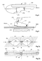
- FIG. 5 shows a clamping device in the area of a kite head.
- Reffseil- and Reffleinen sued not the Reffleinen, but the Reff- and guide rope through the kite head out, contrary to the pictures in FIGS. 3 and 4 ,
- the tug 263 is guided in the region of the kite head by a clamping device 270, which is attached to the kite stick 250.
- Clamping device 270 is designed to clamp both tug lines 263 and reefing lines 262a, b, depending on how far kite 210 is reefed, and thus the position of reefing line 263 and reefing lines 262a, b to the terminal is.
- the clamp 270 includes a tension spring 271 which holds the clamp in a clamped state. That is, in the normal flight condition, the clamp is closed and thus withdrawal of the reef / guide rope 263 from the kite head is not possible. In this way, in the normal flight condition, the guide / guide cable 263 can be used to guide the kite without causing undesirable kite killing.
- the clamp can be opened by manual or automatic actuation of a lever 272. As explained in detail below, this lever can be actuated automatically, in particular, when the kite head is coupled to a mast head on the vessel.
- the clamp 270 Upon actuation of the lever 272, the clamp 270 is released and the guide / guide cable 263 can be pulled out of the kite head. In this way, the reflow lines 262a, b can be pulled out of the kite through the clamp and the kite reefed in this way. Once the refraction is complete, the lever 272 can be released again and the ReffMap be fixed in this way by clamping.
- FIG. 6 shows an alternative embodiment of the clamping device for the Reffleinen or the reff / guide rope.
- the clamping device according to FIG. 8 comprises a fixed mating surface 373 which is provided with a plurality of ribs 374 which increase the friction to the reflec- tors or to the guide / guide cable 362a, b, 363, respectively.
- a pivotable clamping body 375 is arranged, which is pivotally mounted in a rotary joint 376.
- the clamping body 375 is pressed into the clamping position by means of a compression spring 371 and likewise has a multiplicity of ribs 377 on the clamping surface facing the guide / guide cable or the reflec- tors, which increase the friction.
- a Klemmatsleine 378 Adjacent to the articulation point of the compression spring 371 on the clamping lever 375 a Klemmatsleine 378 is attached to the clamp body.
- the clamp release line 378 is deflected and led out of the kite head parallel to the reflow lines 363a, b.
- the clamp body 375 can be pivoted out of the clamping position and consequently the refleel lines 362a, b released to perform the refining.
- This embodiment has the advantage that a cancellation of the clamping effect is also possible by remote control, for example, when a refraction is desired and the kite head is not coupled to a mast head.
- FIGS. 7a and 7b show schematically a vent 80a, b for venting the interior of the kite, which can be variably opened and closed.
- the vent opening is designed as a longitudinal slot and has two mutually parallel longitudinal edges 81, 82.
- longitudinal edges 81, 82 flexible slats are used.
- the slats are firmly connected at three points 83a-c.
- Parallel to the slats extends between the fixed point 83a and the fixed point 83b an opening line with a first opening line portion 84a, which is deflected by a guide roller 85 by 90 ° and is guided to a guide roller 86.
- the first opening line section 84a is deflected by 180 °, so that it runs back to the deflection roller 85a.
- the returning line section is part of a second opening line section 82b, which in turn is deflected by 90 ° on the deflection roller 85 and then extends between the fixed points 83b and 83c.
- the first opening line portion 84a is fixed in the fixed point 83a
- the second opening line portion 84b is fixed in the fixed point 83c, so that the first and second opening line portions 84a, b together represent a line connection between the fixed point 83a and the fixed point 83c, which is deflected at the deflection rollers 85, 86.
- the second deflection roller 86 is connected to a ⁇ réelleszugseil 87.
- this opening tension cable 87 is not tensioned. If the ⁇ réelleszugseil 87 tensioned, as in Figure 7a indicated by an arrow on the opening pull rope, the opening line sections 84a, b are also tensioned and consequently the fixed points 83a, c are pulled in the direction of the fixed point 83b. The slats 81, 82 are thereby deformed and form an eight-shaped opening 80a, b, through which the air located in the interior of the kite can flow.
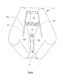
- FIGS. 8 and 9 show a coupling device that can be mounted in the region of a mast head to the top of a mast mounted on a watercraft.
- the mast, mast head and coupling device serve to allow the kite to start and recover. After the start, the Glasseilkraft the kite is transmitted via a distance from the pole arranged Holeddling and the mast is during normal driving without function, so that it can be, for example, telescopically constructed and then retracted.
- FIG. 8 shows the coupling device from the top front.
- the coupling device 90 includes a housing having sidewalls 91 a, b, which laterally delimit a receiving space.
- the recording room is open to the top and to the front.
- To the rear of the receiving space 92 is limited by a stop wall 93.
- the side walls 91a, b converge from top to bottom so that a funnel shape is formed in this direction.
- the side walls 91 a, b are rounded at the front and top edges. Both this rounding and the tapered arrangement of the side walls 91 a, b facilitates the insertion of a kite head into the receiving space 92.
- the coupling device In the rear area behind the stop wall 93, the horizontal and Vertikalverschwenkungsmechanik the coupling device is arranged. This will be described in detail below.
- a locking plate 94 is arranged, which is guided in guide rails 95a, b, which extend horizontally along the side walls 91 a, b.
- the locking plate 94 may be formed along the guide rails 95a, b of FIG FIG. 10 shown locked position in a locked position in which it closes the receiving space 92 from above and thus locks a kite head arranged in the receiving space.
- an opening 96 is arranged, which extends downwards through the coupling device and is arranged so that it directs a guide cable or a guide / guide cable on a guide roller 97, in particular from FIG. 11 can be seen.
- a kite head can be directed into the receiving space 92.
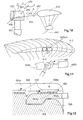
- FIG. 10 FIG. 12 schematically illustrates docking and launching of a kite 410 to a coupling device 490 disposed on a telescoping mast 500.
- the kite 410 approaches with a kite head 492 at the forward end in strong wind in the horizontal direction of the coupling device 490.
- the kite head 452 in this case enters from the front a receiving space 492 a. This movement is guided and supported by a guide cable 463.
- the guide cable 463 is detachably attached to the pull cable 443 in normal flight operation and is removed after the pulling cable has been pulled by the pull cable 443, guided through the opening 496 in the coupling device and can then pull the kite head 452 into the receiving space 492.
- the double arrow marked B indicates the direction in which the kite head 452 is recovered in low wind conditions. In this case, it is necessary to insert the kite head 452 in the receiving space 492 in a direction obliquely from the top front.
- the double arrow marked C indicates the direction in which the kite head 452 is typically started.
- the starting process preferably takes place upwards for the sake of control, i. in a vertical direction of movement.
- FIG. 12 12 shows a cross-sectional side view of coupling device 590 with kite head 552 coupled in.
- Kite head 552 includes a front section 552a and an elongate rear section 552b.
- the elongate rear portion 552b is retracted at the bottom opposite the front portion 552a, so that a step is formed between the front and rear portions 552a, b.
- the lower receiving surface of the receiving space 592 is provided at the front end with a projection 598, which is formed congruent to the step on the kite head 552.
- a locking plate 594 is shown in Figure 14 in two positions.
- Position 594a represents the unlatched position in which the kite head 552 can be moved in and out of the receiving space 592.
- the lock position 594b becomes reached.
- the locking plate 594 is located above the kite head 552, thus preventing the kite head from moving upwardly.
- the stop on the projection 598 with the front kite head portion 552a the kite head is thus locked in the coupling device.
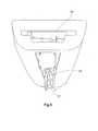
- FIG. 11 schematically shows a kite 610 with two arranged around the central longitudinal axis ventilation openings 620a, b.
- the ventilation openings are arranged in the longitudinal direction of the kite to the left and right of a kite stick (not shown).
- FIG. 11 a coupling device 690 shown.
- the coupling device comprises two cover plates 699a, b attached to the coupling device such that, when the kite 610 is coupled to the coupling device 690, they cover the ventilation openings 620a, b. In this way, further ventilation of the interior of the kite 610 is avoided, thus facilitating the refolding of the kite 610.
- An actuating lever is arranged in the region of the kite head and coupled with a clamping device for the Reffleinen or the reff / guide cable.
- the actuating lever 672 is pivoted when abutted against the mast head by abutting the mast head and releases the clamping of the clamping device.
- FIGS. 13a-c show the mechanical connection device of the coupling device according to the FIGS. 10, 11 on a mast.
- a plate 700 and a plate 701, which is arranged perpendicular to the plate 700, are rigidly attached to the mast.
- a rotation axis 702 is rotatably mounted, which is connected to cantilever arms 704, 705.
- a guide roller 797 is rotatably mounted, which serves for the deflection of the guide cable when guiding the kite head into or out of the receiving space.
- the rotational movement about the axis of rotation 702 is achieved by means of a damper element 706, which is fastened with one end to the plate 700 and with the other End attached to a boom arm 707, which in turn is attached to the boom 704 attached.
- the rotation axis 702 thus enables a pivoting of the coupling device about a vertical axis.
- a pivoting device is arranged, which allows a small pivoting of two boom arms 708, 709 about a horizontal axis.
- This passive pivotability about a horizontal axis allows the kite in the coupled state a certain mobility and thus serves to relieve the kite stick in case of force on the kite, which can be caused for example by gusts of wind or ship movements.
- the kite can be lowered by pivoting about this axis.
Landscapes
- Engineering & Computer Science (AREA)
- Chemical & Material Sciences (AREA)
- Combustion & Propulsion (AREA)
- Mechanical Engineering (AREA)
- Ocean & Marine Engineering (AREA)
- Life Sciences & Earth Sciences (AREA)
- Sustainable Development (AREA)
- Sustainable Energy (AREA)
- Catching Or Destruction (AREA)
- Compositions Of Oxide Ceramics (AREA)
- Manufacture And Refinement Of Metals (AREA)
- Details Of Cameras Including Film Mechanisms (AREA)
- Processing And Handling Of Plastics And Other Materials For Molding In General (AREA)
- Laying Of Electric Cables Or Lines Outside (AREA)
- Toys (AREA)
- Devices For Checking Fares Or Tickets At Control Points (AREA)
- Wind Motors (AREA)
- Transducers For Ultrasonic Waves (AREA)
- Other Liquid Machine Or Engine Such As Wave Power Use (AREA)
- Orthopedics, Nursing, And Contraception (AREA)
- Refinement Of Pig-Iron, Manufacture Of Cast Iron, And Steel Manufacture Other Than In Revolving Furnaces (AREA)
- Adjustment Of The Magnetic Head Position Track Following On Tapes (AREA)
- Input Circuits Of Receivers And Coupling Of Receivers And Audio Equipment (AREA)
Priority Applications (3)
| Application Number | Priority Date | Filing Date | Title |
|---|---|---|---|
| PL11189912T PL2426048T3 (pl) | 2006-08-15 | 2006-08-15 | Aerodynamiczny element profilowany i urządzenie do jego startu i zwijania |
| EP11189912.6A EP2426048B1 (fr) | 2006-08-15 | 2006-08-15 | Élément profilé aérodynamique et dispositif de commencement et rangement pour celui. |
| DK11189912.6T DK2426048T3 (da) | 2006-08-15 | 2006-08-15 | Aerodynamisk profilelement og start- og bjærgningsindretning til dette |
Applications Claiming Priority (4)
| Application Number | Priority Date | Filing Date | Title |
|---|---|---|---|
| PCT/EP2006/008049 WO2008019700A1 (fr) | 2006-08-15 | 2006-08-15 | Dispositif de démarrage et de récupération pour élément profilé aérodynamique et élément profilé aérodynamique |
| EP06776857A EP2054295B1 (fr) | 2006-08-15 | 2006-08-15 | Dispositif de demarrage et de recuperation pour element profile aerodynamique et element profile aerodynamique |
| EP10161062.4A EP2213568B1 (fr) | 2006-08-15 | 2006-08-15 | Dispositif de lancement et de récupération pour un élément profilé aérodynamique |
| EP11189912.6A EP2426048B1 (fr) | 2006-08-15 | 2006-08-15 | Élément profilé aérodynamique et dispositif de commencement et rangement pour celui. |
Related Parent Applications (2)
| Application Number | Title | Priority Date | Filing Date |
|---|---|---|---|
| EP06776857.2 Division | 2006-08-15 | ||
| EP10161062.4 Division | 2010-04-26 |
Publications (3)
| Publication Number | Publication Date |
|---|---|
| EP2426048A2 true EP2426048A2 (fr) | 2012-03-07 |
| EP2426048A3 EP2426048A3 (fr) | 2012-03-21 |
| EP2426048B1 EP2426048B1 (fr) | 2013-07-10 |
Family
ID=38098584
Family Applications (3)
| Application Number | Title | Priority Date | Filing Date |
|---|---|---|---|
| EP11189912.6A Active EP2426048B1 (fr) | 2006-08-15 | 2006-08-15 | Élément profilé aérodynamique et dispositif de commencement et rangement pour celui. |
| EP06776857A Not-in-force EP2054295B1 (fr) | 2006-08-15 | 2006-08-15 | Dispositif de demarrage et de recuperation pour element profile aerodynamique et element profile aerodynamique |
| EP10161062.4A Active EP2213568B1 (fr) | 2006-08-15 | 2006-08-15 | Dispositif de lancement et de récupération pour un élément profilé aérodynamique |
Family Applications After (2)
| Application Number | Title | Priority Date | Filing Date |
|---|---|---|---|
| EP06776857A Not-in-force EP2054295B1 (fr) | 2006-08-15 | 2006-08-15 | Dispositif de demarrage et de recuperation pour element profile aerodynamique et element profile aerodynamique |
| EP10161062.4A Active EP2213568B1 (fr) | 2006-08-15 | 2006-08-15 | Dispositif de lancement et de récupération pour un élément profilé aérodynamique |
Country Status (14)
| Country | Link |
|---|---|
| US (1) | US7287481B1 (fr) |
| EP (3) | EP2426048B1 (fr) |
| JP (1) | JP2010500221A (fr) |
| KR (1) | KR101442277B1 (fr) |
| CN (1) | CN101511671B (fr) |
| AT (1) | ATE465940T1 (fr) |
| AU (1) | AU2006347219B2 (fr) |
| CY (1) | CY1110189T1 (fr) |
| DE (1) | DE502006006875D1 (fr) |
| DK (3) | DK2426048T3 (fr) |
| NZ (1) | NZ573912A (fr) |
| PL (3) | PL2426048T3 (fr) |
| PT (1) | PT2054295E (fr) |
| WO (1) | WO2008019700A1 (fr) |
Families Citing this family (40)
| Publication number | Priority date | Publication date | Assignee | Title |
|---|---|---|---|---|
| DE102004018837A1 (de) * | 2004-04-19 | 2005-11-03 | Skysails Gmbh | Wasserfahrzeug mit einem frei ausfliegenden drachenartigen Windangriffselement als Windantrieb |
| US9521858B2 (en) | 2005-10-21 | 2016-12-20 | Allen Szydlowski | Method and system for recovering and preparing glacial water |
| US9010261B2 (en) | 2010-02-11 | 2015-04-21 | Allen Szydlowski | Method and system for a towed vessel suitable for transporting liquids |
| EP2231470B1 (fr) * | 2007-12-19 | 2011-09-07 | Skysails GmbH & Co. KG | Dispositif de propulsion éolienne aérodynamique ayant des lignes de direction actives et passives et procédé de commande d'un tel dispositif |
| DK2285667T3 (da) * | 2008-05-30 | 2013-01-07 | Skysails Gmbh & Co Kg | Sejl af dragetypen med forbedret linefastgørelse |
| US7775483B2 (en) * | 2008-12-03 | 2010-08-17 | Gaylord G Olson | Launch and recovery system for tethered airborne elements |
| US9371114B2 (en) | 2009-10-15 | 2016-06-21 | Allen Szydlowski | Method and system for a towed vessel suitable for transporting liquids |
| US8924311B2 (en) | 2009-10-15 | 2014-12-30 | World's Fresh Waters Pte. Ltd. | Method and system for processing glacial water |
| US9017123B2 (en) | 2009-10-15 | 2015-04-28 | Allen Szydlowski | Method and system for a towed vessel suitable for transporting liquids |
| WO2011076270A1 (fr) * | 2009-12-22 | 2011-06-30 | Philippe Dubois | Mécanismes de commande de stabilisation et d'orientation pour ailes ou voiles de traction comprenant une aile |
| US11584483B2 (en) | 2010-02-11 | 2023-02-21 | Allen Szydlowski | System for a very large bag (VLB) for transporting liquids powered by solar arrays |
| CN103249945A (zh) * | 2010-08-05 | 2013-08-14 | 侧风能源系统公司 | 使用系留翼面来利用风能的方法和系统 |
| EP2674430A4 (fr) | 2011-02-07 | 2014-07-02 | Daiichi Sankyo Co Ltd | Dérivé de pyrrolidinone contenant un groupe amino |
| DE202011102743U1 (de) | 2011-07-04 | 2012-11-15 | Skysails Gmbh | Vorrichtung zur Steuerung eines gefesselten Flugelements |
| EP3176428A1 (fr) * | 2011-12-18 | 2017-06-07 | X Development LLC | Station terrestre de cerf-volant et système l'utilisant |
| US8888049B2 (en) | 2011-12-18 | 2014-11-18 | Google Inc. | Kite ground station and system using same |
| EP2831410A2 (fr) | 2012-03-27 | 2015-02-04 | E-Kite Holding B.V. | Système d'énergie à cerf-volant |
| CN104379443A (zh) | 2012-05-03 | 2015-02-25 | 天帆有限责任公司 | 气动风能转换装置及控制该装置的方法 |
| EP2844553A1 (fr) | 2012-05-03 | 2015-03-11 | Skysails GmbH | Ensemble mât et procédé de lancement et d'atterrissage d'une aile aérodynamique |
| MX360227B (es) * | 2013-01-16 | 2018-09-19 | Omar Fernandez Gonzalez Jesus | Dispositivo eólico flexible generador de sombra para protección solar. |
| US20150233254A1 (en) * | 2014-02-17 | 2015-08-20 | Edmund Daniel Villarreal | Vented airfoil assemblies |
| CN103786883A (zh) * | 2014-02-23 | 2014-05-14 | 周振文 | 御风筝及其飞行方法 |
| CN104488587B (zh) * | 2014-12-22 | 2016-08-17 | 中国科学院南京地理与湖泊研究所 | 一种生态钵布放装置及布放方法 |
| DE102015111224B4 (de) | 2015-07-10 | 2024-06-13 | Skysails Gmbh | Start- und Bergevorrichtung für einen Zugdrachen |
| FR3068332B1 (fr) * | 2017-06-30 | 2019-07-26 | Ocea | Structure de cerf-volant |
| US10569871B2 (en) * | 2017-09-07 | 2020-02-25 | Maritime Applied Physics Corporation | Apparatus, device and method for automated launch and recovery of a kite |
| EP3453608B1 (fr) | 2017-09-07 | 2020-11-04 | SkySails Power GmbH | Procédé et système d'arrimage d'un élément soumis à l'action du vent |
| CN108001696B (zh) * | 2017-11-29 | 2021-01-01 | 中国航空工业集团公司洛阳电光设备研究所 | 一种机载紧凑型光电吊舱 |
| CN107891960A (zh) * | 2017-12-14 | 2018-04-10 | 浙江海洋大学 | 一种筝帆应急保护机构、筝帆及船舶 |
| CN107878721B (zh) * | 2017-12-14 | 2023-05-05 | 浙江海洋大学 | 一种船用筝帆及船舶 |
| FR3076811B1 (fr) * | 2018-01-16 | 2022-03-18 | Ensta Bretagne | Bateau comportant un cerf-volant |
| NL2020673B1 (en) * | 2018-03-27 | 2019-10-03 | Enevate B V | Airborne wind energy system |
| FR3082185B1 (fr) * | 2018-06-11 | 2020-10-02 | Airseas | Systeme de traction comprenant au moins deux voiles captives avec un mat pourvu de moyens d'accostage distincts dedies chacun a une voile |
| FR3082184B1 (fr) * | 2018-06-11 | 2020-07-03 | Airseas | Systeme comprenant une voile captive et un poste fixe avec des moyens de pliage de la voile au poste fixe |
| FR3120845B1 (fr) * | 2021-03-19 | 2023-03-10 | Airseas | Système de traction à aile captive avec pliage en manche à air |
| FR3120846B1 (fr) * | 2021-03-19 | 2023-12-29 | Airseas | Système de traction à aile captive avec dispositif de saisie des lignes de pliage |
| FR3120847B1 (fr) * | 2021-03-19 | 2023-03-10 | Airseas | Système de traction à aile captive et procédé de déplacement des charriots |
| US12151822B1 (en) * | 2021-09-20 | 2024-11-26 | The United States Of America, As Represented By The Secretary Of The Navy | Geometry adaptable supported parafoil |
| EP4234401A1 (fr) | 2022-02-28 | 2023-08-30 | SkySails Power GmbH | Procédé d'atterrissage d'un système de cerf-volant et système de cerf-volant |
| FR3133833A1 (fr) * | 2022-03-25 | 2023-09-29 | Maloric | Systeme de commande automatique d’une aile de traction |
Citations (2)
| Publication number | Priority date | Publication date | Assignee | Title |
|---|---|---|---|---|
| WO2006027194A1 (fr) | 2004-09-06 | 2006-03-16 | Skysails Gmbh & Co. Kg | Embarcation a element de type cerf-volant |
| WO2006027195A1 (fr) | 2004-09-06 | 2006-03-16 | Skysails Gmbh & Co. Kg | Embarcation a element de type cerf-volant |
Family Cites Families (17)
| Publication number | Priority date | Publication date | Assignee | Title |
|---|---|---|---|---|
| BE884431A (fr) * | 1979-07-19 | 1981-01-23 | Jones Andrew W | Structure de voilure |
| GB2098950A (en) * | 1981-05-21 | 1982-12-01 | British Petroleum Co Plc | Launching tethered sails for marine or other uses |
| US5201482A (en) * | 1991-10-30 | 1993-04-13 | Ream Stanley M | RAM air inflatable gliding wing |
| US5244169A (en) * | 1992-05-15 | 1993-09-14 | Vertigo, Inc. | Inflatable structure paraglider |
| DE19957207A1 (de) * | 1999-11-27 | 2001-05-31 | Gabor Kovacs | Schwimmfähiger Zugschirm |
| DE19961035A1 (de) * | 1999-12-16 | 2001-07-05 | Fly Market Flugsport Zubehoer | Paragleiter |
| AU3624101A (en) * | 2000-02-10 | 2001-08-20 | Peter Robert Lynn | Ram air inflated wing |
| WO2001092102A1 (fr) * | 2000-05-31 | 2001-12-06 | Stephan Wrage | Bateau entraine par energie eolienne |
| DE10109640C1 (de) * | 2001-03-01 | 2002-06-20 | Friedrich Van Helden | Lenkbarer Zugdrachen |
| US20030106479A1 (en) * | 2001-10-09 | 2003-06-12 | Suh Sung J. | Kiting system on a sitting board |
| FR2837166B1 (fr) * | 2002-03-18 | 2004-11-12 | Pascal Vincent Pillon | Structures gonflable segmentees generalement utilisees pour les ailes de traction a structure gonflable |
| AU2003241483A1 (en) * | 2002-05-14 | 2003-11-11 | Nalu Kai Incorporated | Push release loop |
| US6789489B1 (en) * | 2003-06-11 | 2004-09-14 | Jeffrey S. Phipps | Sailboat with gimbaled mast and keel |
| KR200336385Y1 (ko) * | 2003-07-18 | 2003-12-24 | 서성준 | 보드 카이팅을 위한 착석 보드 |
| DE102004018838A1 (de) | 2004-04-19 | 2005-11-03 | Skysails Gmbh | Positionierungsvorrichtung für ein frei ausfliegendes drachenartiges Windangriffselement bei einem Wasserfahrzeug mit Windantrieb |
| DE102004018814A1 (de) * | 2004-04-19 | 2005-11-03 | Skysails Gmbh | Setzsystem für ein ausfliegendes drachenartiges Windangriffselement bei einem Wasserfahrzeug mit Windantrieb |
| US7104504B2 (en) * | 2004-09-24 | 2006-09-12 | Alex Peterson | Inflatable wing with active canopy profile control |
-
2006
- 2006-08-15 EP EP11189912.6A patent/EP2426048B1/fr active Active
- 2006-08-15 WO PCT/EP2006/008049 patent/WO2008019700A1/fr not_active Ceased
- 2006-08-15 PL PL11189912T patent/PL2426048T3/pl unknown
- 2006-08-15 PT PT06776857T patent/PT2054295E/pt unknown
- 2006-08-15 JP JP2009524080A patent/JP2010500221A/ja active Pending
- 2006-08-15 DK DK11189912.6T patent/DK2426048T3/da active
- 2006-08-15 PL PL10161062T patent/PL2213568T3/pl unknown
- 2006-08-15 KR KR1020097003787A patent/KR101442277B1/ko not_active Expired - Fee Related
- 2006-08-15 CN CN2006800556105A patent/CN101511671B/zh not_active Expired - Fee Related
- 2006-08-15 NZ NZ573912A patent/NZ573912A/en not_active IP Right Cessation
- 2006-08-15 EP EP06776857A patent/EP2054295B1/fr not_active Not-in-force
- 2006-08-15 AT AT06776857T patent/ATE465940T1/de active
- 2006-08-15 DK DK10161062.4T patent/DK2213568T3/da active
- 2006-08-15 DE DE502006006875T patent/DE502006006875D1/de active Active
- 2006-08-15 EP EP10161062.4A patent/EP2213568B1/fr active Active
- 2006-08-15 PL PL06776857T patent/PL2054295T3/pl unknown
- 2006-08-15 AU AU2006347219A patent/AU2006347219B2/en not_active Ceased
- 2006-08-15 DK DK06776857.2T patent/DK2054295T3/da active
- 2006-09-29 US US11/529,902 patent/US7287481B1/en active Active - Reinstated
-
2010
- 2010-07-13 CY CY20101100652T patent/CY1110189T1/el unknown
Patent Citations (2)
| Publication number | Priority date | Publication date | Assignee | Title |
|---|---|---|---|---|
| WO2006027194A1 (fr) | 2004-09-06 | 2006-03-16 | Skysails Gmbh & Co. Kg | Embarcation a element de type cerf-volant |
| WO2006027195A1 (fr) | 2004-09-06 | 2006-03-16 | Skysails Gmbh & Co. Kg | Embarcation a element de type cerf-volant |
Also Published As
| Publication number | Publication date |
|---|---|
| DK2213568T3 (da) | 2013-07-15 |
| AU2006347219B2 (en) | 2012-12-06 |
| DE502006006875D1 (de) | 2010-06-10 |
| PL2054295T3 (pl) | 2010-10-29 |
| KR101442277B1 (ko) | 2014-09-22 |
| JP2010500221A (ja) | 2010-01-07 |
| EP2213568A1 (fr) | 2010-08-04 |
| PL2426048T3 (pl) | 2013-12-31 |
| WO2008019700A1 (fr) | 2008-02-21 |
| ATE465940T1 (de) | 2010-05-15 |
| PL2213568T3 (pl) | 2013-09-30 |
| HK1147082A1 (en) | 2011-07-29 |
| EP2426048B1 (fr) | 2013-07-10 |
| CY1110189T1 (el) | 2015-01-14 |
| EP2213568B1 (fr) | 2013-05-01 |
| EP2054295A1 (fr) | 2009-05-06 |
| AU2006347219A1 (en) | 2008-02-21 |
| KR20090038917A (ko) | 2009-04-21 |
| US7287481B1 (en) | 2007-10-30 |
| CN101511671B (zh) | 2013-01-02 |
| EP2426048A3 (fr) | 2012-03-21 |
| NZ573912A (en) | 2012-05-25 |
| DK2054295T3 (da) | 2010-07-26 |
| CN101511671A (zh) | 2009-08-19 |
| DK2426048T3 (da) | 2013-09-08 |
| PT2054295E (pt) | 2010-06-11 |
| HK1129875A1 (zh) | 2009-12-11 |
| EP2054295B1 (fr) | 2010-04-28 |
Similar Documents
| Publication | Publication Date | Title |
|---|---|---|
| EP2054295B1 (fr) | Dispositif de demarrage et de recuperation pour element profile aerodynamique et element profile aerodynamique | |
| DE102018100696B4 (de) | Surfboard mit Wechselakkumulator und Hochdrückmechanismus | |
| DE3011416C2 (de) | Karabinerhaken | |
| DE20107925U1 (de) | Leinensystem zum Steuern eines Kites | |
| DE2619951C2 (de) | Einrichtung zum vorwärtsbewegenden Antreiben des menschlichen Körpers | |
| DE102015111224B4 (de) | Start- und Bergevorrichtung für einen Zugdrachen | |
| DE2933050A1 (de) | Einrichtung zum vorwaertsbewegenden antreiben eines koerpers durch windkraft mittels eines segels | |
| DE2509855A1 (de) | Lamellensegel fuer boote | |
| DE102010028216A1 (de) | Halte- und Steuervorrichtung für einen Lenkdrachen | |
| DE112013002436T5 (de) | Sicherungssystem für einen Zugdrachen mit lösbarem, verstellbarem Stangenstopper | |
| WO2017008924A1 (fr) | Système de sauvetage d'un homme à la mer pour embarcations | |
| DE102018100345A1 (de) | Bemannter Drachen mit variablem Flügelprofil | |
| DE2549393A1 (de) | Deltagleiter | |
| DE202009002826U1 (de) | Sicherheitseinrichtung an der Zugleine großer Lenkdrachen | |
| DE3213254A1 (de) | Segelbrett mit als besonderheit ein reff- und trimmbares rigg | |
| DE3104750A1 (de) | Rigg in tragfluegelform fuer besegelte fahrzeuge | |
| DE102019128097B4 (de) | Steuervorrichtung für eine Drohne | |
| WO2005023631A2 (fr) | Systeme de securite ameliore pour cerf-volant a quatre suspentes | |
| DE2642391A1 (de) | Triebwerk fuer modellflugzeuge | |
| EP4119438A1 (fr) | Dispositif et procédé de protection d'une voile | |
| DE2365104A1 (de) | Flugzeug mit flexiblen fluegeln | |
| EP4417932A1 (fr) | Guidage sécurisé d'un câble sur un sous-marin | |
| DE3842612A1 (de) | Gleitschirm mit hohen gleitzahlen fuer personen und lasten | |
| DE10251284A1 (de) | Trimm - Lande Relaunch -Sicherheits Vorrichtung zum Kitesurfen | |
| DE4205156A1 (de) | Flugzeug-segelfluegel mit variabler auftriebserzeugender flaechengroesse |
Legal Events
| Date | Code | Title | Description |
|---|---|---|---|
| PUAL | Search report despatched |
Free format text: ORIGINAL CODE: 0009013 |
|
| AC | Divisional application: reference to earlier application |
Ref document number: 2213568 Country of ref document: EP Kind code of ref document: P Ref document number: 2054295 Country of ref document: EP Kind code of ref document: P |
|
| AK | Designated contracting states |
Kind code of ref document: A2 Designated state(s): AT BE BG CH CY CZ DE DK EE ES FI FR GB GR HU IE IS IT LI LT LU LV MC NL PL PT RO SE SI SK TR |
|
| PUAI | Public reference made under article 153(3) epc to a published international application that has entered the european phase |
Free format text: ORIGINAL CODE: 0009012 |
|
| AK | Designated contracting states |
Kind code of ref document: A3 Designated state(s): AT BE BG CH CY CZ DE DK EE ES FI FR GB GR HU IE IS IT LI LT LU LV MC NL PL PT RO SE SI SK TR |
|
| RIC1 | Information provided on ipc code assigned before grant |
Ipc: B64C 31/06 20060101ALI20120216BHEP Ipc: B63B 35/79 20060101AFI20120216BHEP Ipc: B63H 9/06 20060101ALI20120216BHEP Ipc: B63B 15/00 20060101ALI20120216BHEP |
|
| 17P | Request for examination filed |
Effective date: 20120921 |
|
| GRAP | Despatch of communication of intention to grant a patent |
Free format text: ORIGINAL CODE: EPIDOSNIGR1 |
|
| GRAS | Grant fee paid |
Free format text: ORIGINAL CODE: EPIDOSNIGR3 |
|
| GRAA | (expected) grant |
Free format text: ORIGINAL CODE: 0009210 |
|
| AC | Divisional application: reference to earlier application |
Ref document number: 2213568 Country of ref document: EP Kind code of ref document: P Ref document number: 2054295 Country of ref document: EP Kind code of ref document: P |
|
| AK | Designated contracting states |
Kind code of ref document: B1 Designated state(s): AT BE BG CH CY CZ DE DK EE ES FI FR GB GR HU IE IS IT LI LT LU LV MC NL PL PT RO SE SI SK TR |
|
| REG | Reference to a national code |
Ref country code: GB Ref legal event code: FG4D Free format text: NOT ENGLISH |
|
| REG | Reference to a national code |
Ref country code: CH Ref legal event code: EP Ref country code: AT Ref legal event code: REF Ref document number: 620805 Country of ref document: AT Kind code of ref document: T Effective date: 20130715 |
|
| REG | Reference to a national code |
Ref country code: CH Ref legal event code: NV Representative=s name: RENTSCH PARTNER AG, CH |
|
| REG | Reference to a national code |
Ref country code: IE Ref legal event code: FG4D Free format text: LANGUAGE OF EP DOCUMENT: GERMAN |
|
| REG | Reference to a national code |
Ref country code: DK Ref legal event code: T3 |
|
| REG | Reference to a national code |
Ref country code: DE Ref legal event code: R096 Ref document number: 502006013013 Country of ref document: DE Effective date: 20130912 |
|
| REG | Reference to a national code |
Ref country code: SE Ref legal event code: TRGR |
|
| PG25 | Lapsed in a contracting state [announced via postgrant information from national office to epo] |
Ref country code: SI Free format text: LAPSE BECAUSE OF FAILURE TO SUBMIT A TRANSLATION OF THE DESCRIPTION OR TO PAY THE FEE WITHIN THE PRESCRIBED TIME-LIMIT Effective date: 20130710 |
|
| REG | Reference to a national code |
Ref country code: NL Ref legal event code: T3 |
|
| REG | Reference to a national code |
Ref country code: LT Ref legal event code: MG4D |
|
| REG | Reference to a national code |
Ref country code: PL Ref legal event code: T3 |
|
| PG25 | Lapsed in a contracting state [announced via postgrant information from national office to epo] |
Ref country code: CY Free format text: LAPSE BECAUSE OF FAILURE TO SUBMIT A TRANSLATION OF THE DESCRIPTION OR TO PAY THE FEE WITHIN THE PRESCRIBED TIME-LIMIT Effective date: 20130814 Ref country code: PT Free format text: LAPSE BECAUSE OF FAILURE TO SUBMIT A TRANSLATION OF THE DESCRIPTION OR TO PAY THE FEE WITHIN THE PRESCRIBED TIME-LIMIT Effective date: 20131111 Ref country code: LT Free format text: LAPSE BECAUSE OF FAILURE TO SUBMIT A TRANSLATION OF THE DESCRIPTION OR TO PAY THE FEE WITHIN THE PRESCRIBED TIME-LIMIT Effective date: 20130710 Ref country code: IS Free format text: LAPSE BECAUSE OF FAILURE TO SUBMIT A TRANSLATION OF THE DESCRIPTION OR TO PAY THE FEE WITHIN THE PRESCRIBED TIME-LIMIT Effective date: 20131110 |
|
| BERE | Be: lapsed |
Owner name: SKYSAILS G.M.B.H. Effective date: 20130831 |
|
| PG25 | Lapsed in a contracting state [announced via postgrant information from national office to epo] |
Ref country code: GR Free format text: LAPSE BECAUSE OF FAILURE TO SUBMIT A TRANSLATION OF THE DESCRIPTION OR TO PAY THE FEE WITHIN THE PRESCRIBED TIME-LIMIT Effective date: 20131011 Ref country code: LV Free format text: LAPSE BECAUSE OF FAILURE TO SUBMIT A TRANSLATION OF THE DESCRIPTION OR TO PAY THE FEE WITHIN THE PRESCRIBED TIME-LIMIT Effective date: 20130710 Ref country code: ES Free format text: LAPSE BECAUSE OF FAILURE TO SUBMIT A TRANSLATION OF THE DESCRIPTION OR TO PAY THE FEE WITHIN THE PRESCRIBED TIME-LIMIT Effective date: 20131021 Ref country code: FI Free format text: LAPSE BECAUSE OF FAILURE TO SUBMIT A TRANSLATION OF THE DESCRIPTION OR TO PAY THE FEE WITHIN THE PRESCRIBED TIME-LIMIT Effective date: 20130710 |
|
| PG25 | Lapsed in a contracting state [announced via postgrant information from national office to epo] |
Ref country code: CY Free format text: LAPSE BECAUSE OF FAILURE TO SUBMIT A TRANSLATION OF THE DESCRIPTION OR TO PAY THE FEE WITHIN THE PRESCRIBED TIME-LIMIT Effective date: 20130710 |
|
| PG25 | Lapsed in a contracting state [announced via postgrant information from national office to epo] |
Ref country code: SK Free format text: LAPSE BECAUSE OF FAILURE TO SUBMIT A TRANSLATION OF THE DESCRIPTION OR TO PAY THE FEE WITHIN THE PRESCRIBED TIME-LIMIT Effective date: 20130710 Ref country code: RO Free format text: LAPSE BECAUSE OF FAILURE TO SUBMIT A TRANSLATION OF THE DESCRIPTION OR TO PAY THE FEE WITHIN THE PRESCRIBED TIME-LIMIT Effective date: 20130710 Ref country code: CZ Free format text: LAPSE BECAUSE OF FAILURE TO SUBMIT A TRANSLATION OF THE DESCRIPTION OR TO PAY THE FEE WITHIN THE PRESCRIBED TIME-LIMIT Effective date: 20130710 Ref country code: MC Free format text: LAPSE BECAUSE OF FAILURE TO SUBMIT A TRANSLATION OF THE DESCRIPTION OR TO PAY THE FEE WITHIN THE PRESCRIBED TIME-LIMIT Effective date: 20130710 Ref country code: EE Free format text: LAPSE BECAUSE OF FAILURE TO SUBMIT A TRANSLATION OF THE DESCRIPTION OR TO PAY THE FEE WITHIN THE PRESCRIBED TIME-LIMIT Effective date: 20130710 |
|
| PLBE | No opposition filed within time limit |
Free format text: ORIGINAL CODE: 0009261 |
|
| STAA | Information on the status of an ep patent application or granted ep patent |
Free format text: STATUS: NO OPPOSITION FILED WITHIN TIME LIMIT |
|
| PG25 | Lapsed in a contracting state [announced via postgrant information from national office to epo] |
Ref country code: BE Free format text: LAPSE BECAUSE OF NON-PAYMENT OF DUE FEES Effective date: 20130831 |
|
| 26N | No opposition filed |
Effective date: 20140411 |
|
| REG | Reference to a national code |
Ref country code: DE Ref legal event code: R097 Ref document number: 502006013013 Country of ref document: DE Effective date: 20140411 |
|
| PG25 | Lapsed in a contracting state [announced via postgrant information from national office to epo] |
Ref country code: LU Free format text: LAPSE BECAUSE OF NON-PAYMENT OF DUE FEES Effective date: 20130815 Ref country code: BG Free format text: LAPSE BECAUSE OF FAILURE TO SUBMIT A TRANSLATION OF THE DESCRIPTION OR TO PAY THE FEE WITHIN THE PRESCRIBED TIME-LIMIT Effective date: 20130710 Ref country code: HU Free format text: LAPSE BECAUSE OF FAILURE TO SUBMIT A TRANSLATION OF THE DESCRIPTION OR TO PAY THE FEE WITHIN THE PRESCRIBED TIME-LIMIT; INVALID AB INITIO Effective date: 20060815 |
|
| REG | Reference to a national code |
Ref country code: FR Ref legal event code: PLFP Year of fee payment: 10 |
|
| PGFP | Annual fee paid to national office [announced via postgrant information from national office to epo] |
Ref country code: NL Payment date: 20150824 Year of fee payment: 10 |
|
| PGFP | Annual fee paid to national office [announced via postgrant information from national office to epo] |
Ref country code: IE Payment date: 20150819 Year of fee payment: 10 Ref country code: CH Payment date: 20150824 Year of fee payment: 10 Ref country code: DK Payment date: 20150825 Year of fee payment: 10 |
|
| PGFP | Annual fee paid to national office [announced via postgrant information from national office to epo] |
Ref country code: SE Payment date: 20150824 Year of fee payment: 10 Ref country code: FR Payment date: 20150824 Year of fee payment: 10 Ref country code: AT Payment date: 20150820 Year of fee payment: 10 Ref country code: PL Payment date: 20150805 Year of fee payment: 10 |
|
| PGFP | Annual fee paid to national office [announced via postgrant information from national office to epo] |
Ref country code: IT Payment date: 20150827 Year of fee payment: 10 |
|
| REG | Reference to a national code |
Ref country code: DE Ref legal event code: R082 Ref document number: 502006013013 Country of ref document: DE Representative=s name: GLAWE DELFS MOLL PARTNERSCHAFT MBB VON PATENT-, DE Ref country code: DE Ref legal event code: R082 Ref document number: 502006013013 Country of ref document: DE |
|
| REG | Reference to a national code |
Ref country code: DE Ref legal event code: R082 Ref document number: 502006013013 Country of ref document: DE Representative=s name: GLAWE DELFS MOLL PARTNERSCHAFT MBB VON PATENT-, DE |
|
| REG | Reference to a national code |
Ref country code: DK Ref legal event code: EBP Effective date: 20160831 |
|
| REG | Reference to a national code |
Ref country code: SE Ref legal event code: EUG |
|
| REG | Reference to a national code |
Ref country code: CH Ref legal event code: PL |
|
| REG | Reference to a national code |
Ref country code: NL Ref legal event code: MM Effective date: 20160901 |
|
| REG | Reference to a national code |
Ref country code: AT Ref legal event code: MM01 Ref document number: 620805 Country of ref document: AT Kind code of ref document: T Effective date: 20160815 |
|
| PG25 | Lapsed in a contracting state [announced via postgrant information from national office to epo] |
Ref country code: CH Free format text: LAPSE BECAUSE OF NON-PAYMENT OF DUE FEES Effective date: 20160831 Ref country code: LI Free format text: LAPSE BECAUSE OF NON-PAYMENT OF DUE FEES Effective date: 20160831 Ref country code: SE Free format text: LAPSE BECAUSE OF NON-PAYMENT OF DUE FEES Effective date: 20160816 |
|
| REG | Reference to a national code |
Ref country code: FR Ref legal event code: ST Effective date: 20170428 |
|
| PG25 | Lapsed in a contracting state [announced via postgrant information from national office to epo] |
Ref country code: AT Free format text: LAPSE BECAUSE OF NON-PAYMENT OF DUE FEES Effective date: 20160815 |
|
| REG | Reference to a national code |
Ref country code: IE Ref legal event code: MM4A |
|
| PG25 | Lapsed in a contracting state [announced via postgrant information from national office to epo] |
Ref country code: NL Free format text: LAPSE BECAUSE OF NON-PAYMENT OF DUE FEES Effective date: 20160901 |
|
| PG25 | Lapsed in a contracting state [announced via postgrant information from national office to epo] |
Ref country code: FR Free format text: LAPSE BECAUSE OF NON-PAYMENT OF DUE FEES Effective date: 20160831 Ref country code: IE Free format text: LAPSE BECAUSE OF NON-PAYMENT OF DUE FEES Effective date: 20160815 Ref country code: DK Free format text: LAPSE BECAUSE OF NON-PAYMENT OF DUE FEES Effective date: 20160831 |
|
| PG25 | Lapsed in a contracting state [announced via postgrant information from national office to epo] |
Ref country code: IT Free format text: LAPSE BECAUSE OF NON-PAYMENT OF DUE FEES Effective date: 20160815 |
|
| PGFP | Annual fee paid to national office [announced via postgrant information from national office to epo] |
Ref country code: TR Payment date: 20150815 Year of fee payment: 10 |
|
| PG25 | Lapsed in a contracting state [announced via postgrant information from national office to epo] |
Ref country code: PL Free format text: LAPSE BECAUSE OF NON-PAYMENT OF DUE FEES Effective date: 20160815 |
|
| REG | Reference to a national code |
Ref country code: DE Ref legal event code: R079 Ref document number: 502006013013 Country of ref document: DE Free format text: PREVIOUS MAIN CLASS: B63B0035790000 Ipc: B63B0032000000 |
|
| PG25 | Lapsed in a contracting state [announced via postgrant information from national office to epo] |
Ref country code: TR Free format text: LAPSE BECAUSE OF NON-PAYMENT OF DUE FEES Effective date: 20160815 |
|
| P01 | Opt-out of the competence of the unified patent court (upc) registered |
Effective date: 20230525 |
|
| PGFP | Annual fee paid to national office [announced via postgrant information from national office to epo] |
Ref country code: DE Payment date: 20250825 Year of fee payment: 20 |
|
| PGFP | Annual fee paid to national office [announced via postgrant information from national office to epo] |
Ref country code: GB Payment date: 20250825 Year of fee payment: 20 |