EP2427309B1 - Procédé et dispositif de fabrication d'un fil à partir d'une pluralité de monofilaments - Google Patents
Procédé et dispositif de fabrication d'un fil à partir d'une pluralité de monofilaments Download PDFInfo
- Publication number
- EP2427309B1 EP2427309B1 EP20100718574 EP10718574A EP2427309B1 EP 2427309 B1 EP2427309 B1 EP 2427309B1 EP 20100718574 EP20100718574 EP 20100718574 EP 10718574 A EP10718574 A EP 10718574A EP 2427309 B1 EP2427309 B1 EP 2427309B1
- Authority
- EP
- European Patent Office
- Prior art keywords
- resin
- individual filaments
- filaments
- nozzle
- composite
- Prior art date
- Legal status (The legal status is an assumption and is not a legal conclusion. Google has not performed a legal analysis and makes no representation as to the accuracy of the status listed.)
- Not-in-force
Links
Images

Classifications
-
- B—PERFORMING OPERATIONS; TRANSPORTING
- B29—WORKING OF PLASTICS; WORKING OF SUBSTANCES IN A PLASTIC STATE IN GENERAL
- B29C—SHAPING OR JOINING OF PLASTICS; SHAPING OF MATERIAL IN A PLASTIC STATE, NOT OTHERWISE PROVIDED FOR; AFTER-TREATMENT OF THE SHAPED PRODUCTS, e.g. REPAIRING
- B29C70/00—Shaping composites, i.e. plastics material comprising reinforcements, fillers or preformed parts, e.g. inserts
- B29C70/04—Shaping composites, i.e. plastics material comprising reinforcements, fillers or preformed parts, e.g. inserts comprising reinforcements only, e.g. self-reinforcing plastics
- B29C70/28—Shaping operations therefor
- B29C70/40—Shaping or impregnating by compression not applied
- B29C70/50—Shaping or impregnating by compression not applied for producing articles of indefinite length, e.g. prepregs, sheet moulding compounds [SMC] or cross moulding compounds [XMC]
- B29C70/52—Pultrusion, i.e. forming and compressing by continuously pulling through a die
- B29C70/521—Pultrusion, i.e. forming and compressing by continuously pulling through a die and impregnating the reinforcement before the die
-
- D—TEXTILES; PAPER
- D06—TREATMENT OF TEXTILES OR THE LIKE; LAUNDERING; FLEXIBLE MATERIALS NOT OTHERWISE PROVIDED FOR
- D06C—FINISHING, DRESSING, TENTERING OR STRETCHING TEXTILE FABRICS
- D06C15/00—Calendering, pressing, ironing, glossing or glazing textile fabrics
-
- B—PERFORMING OPERATIONS; TRANSPORTING
- B29—WORKING OF PLASTICS; WORKING OF SUBSTANCES IN A PLASTIC STATE IN GENERAL
- B29B—PREPARATION OR PRETREATMENT OF THE MATERIAL TO BE SHAPED; MAKING GRANULES OR PREFORMS; RECOVERY OF PLASTICS OR OTHER CONSTITUENTS OF WASTE MATERIAL CONTAINING PLASTICS
- B29B15/00—Pretreatment of the material to be shaped, not covered by groups B29B7/00 - B29B13/00
- B29B15/08—Pretreatment of the material to be shaped, not covered by groups B29B7/00 - B29B13/00 of reinforcements or fillers
- B29B15/10—Coating or impregnating independently of the moulding or shaping step
- B29B15/12—Coating or impregnating independently of the moulding or shaping step of reinforcements of indefinite length
- B29B15/122—Coating or impregnating independently of the moulding or shaping step of reinforcements of indefinite length with a matrix in liquid form, e.g. as melt, solution or latex
- B29B15/125—Coating or impregnating independently of the moulding or shaping step of reinforcements of indefinite length with a matrix in liquid form, e.g. as melt, solution or latex by dipping
-
- B—PERFORMING OPERATIONS; TRANSPORTING
- B29—WORKING OF PLASTICS; WORKING OF SUBSTANCES IN A PLASTIC STATE IN GENERAL
- B29B—PREPARATION OR PRETREATMENT OF THE MATERIAL TO BE SHAPED; MAKING GRANULES OR PREFORMS; RECOVERY OF PLASTICS OR OTHER CONSTITUENTS OF WASTE MATERIAL CONTAINING PLASTICS
- B29B15/00—Pretreatment of the material to be shaped, not covered by groups B29B7/00 - B29B13/00
- B29B15/08—Pretreatment of the material to be shaped, not covered by groups B29B7/00 - B29B13/00 of reinforcements or fillers
- B29B15/10—Coating or impregnating independently of the moulding or shaping step
- B29B15/12—Coating or impregnating independently of the moulding or shaping step of reinforcements of indefinite length
- B29B15/14—Coating or impregnating independently of the moulding or shaping step of reinforcements of indefinite length of filaments or wires
-
- D—TEXTILES; PAPER
- D02—YARNS; MECHANICAL FINISHING OF YARNS OR ROPES; WARPING OR BEAMING
- D02G—CRIMPING OR CURLING FIBRES, FILAMENTS, THREADS, OR YARNS; YARNS OR THREADS
- D02G3/00—Yarns or threads, e.g. fancy yarns; Processes or apparatus for the production thereof, not otherwise provided for
- D02G3/22—Yarns or threads characterised by constructional features, e.g. blending, filament/fibre
- D02G3/36—Cored or coated yarns or threads
-
- D—TEXTILES; PAPER
- D02—YARNS; MECHANICAL FINISHING OF YARNS OR ROPES; WARPING OR BEAMING
- D02G—CRIMPING OR CURLING FIBRES, FILAMENTS, THREADS, OR YARNS; YARNS OR THREADS
- D02G3/00—Yarns or threads, e.g. fancy yarns; Processes or apparatus for the production thereof, not otherwise provided for
- D02G3/22—Yarns or threads characterised by constructional features, e.g. blending, filament/fibre
- D02G3/40—Yarns in which fibres are united by adhesives; Impregnated yarns or threads
-
- D—TEXTILES; PAPER
- D06—TREATMENT OF TEXTILES OR THE LIKE; LAUNDERING; FLEXIBLE MATERIALS NOT OTHERWISE PROVIDED FOR
- D06M—TREATMENT, NOT PROVIDED FOR ELSEWHERE IN CLASS D06, OF FIBRES, THREADS, YARNS, FABRICS, FEATHERS OR FIBROUS GOODS MADE FROM SUCH MATERIALS
- D06M10/00—Physical treatment of fibres, threads, yarns, fabrics or fibrous goods made from such materials, e.g. by ultrasonic waves, corona discharge, irradiation, electric currents or magnetic fields; Physical treatment combined with treatment with chemical compounds or elements
-
- Y—GENERAL TAGGING OF NEW TECHNOLOGICAL DEVELOPMENTS; GENERAL TAGGING OF CROSS-SECTIONAL TECHNOLOGIES SPANNING OVER SEVERAL SECTIONS OF THE IPC; TECHNICAL SUBJECTS COVERED BY FORMER USPC CROSS-REFERENCE ART COLLECTIONS [XRACs] AND DIGESTS
- Y10—TECHNICAL SUBJECTS COVERED BY FORMER USPC
- Y10T—TECHNICAL SUBJECTS COVERED BY FORMER US CLASSIFICATION
- Y10T428/00—Stock material or miscellaneous articles
- Y10T428/23907—Pile or nap type surface or component
- Y10T428/23986—With coating, impregnation, or bond
-
- Y—GENERAL TAGGING OF NEW TECHNOLOGICAL DEVELOPMENTS; GENERAL TAGGING OF CROSS-SECTIONAL TECHNOLOGIES SPANNING OVER SEVERAL SECTIONS OF THE IPC; TECHNICAL SUBJECTS COVERED BY FORMER USPC CROSS-REFERENCE ART COLLECTIONS [XRACs] AND DIGESTS
- Y10—TECHNICAL SUBJECTS COVERED BY FORMER USPC
- Y10T—TECHNICAL SUBJECTS COVERED BY FORMER US CLASSIFICATION
- Y10T428/00—Stock material or miscellaneous articles
- Y10T428/249921—Web or sheet containing structurally defined element or component
-
- Y—GENERAL TAGGING OF NEW TECHNOLOGICAL DEVELOPMENTS; GENERAL TAGGING OF CROSS-SECTIONAL TECHNOLOGIES SPANNING OVER SEVERAL SECTIONS OF THE IPC; TECHNICAL SUBJECTS COVERED BY FORMER USPC CROSS-REFERENCE ART COLLECTIONS [XRACs] AND DIGESTS
- Y10—TECHNICAL SUBJECTS COVERED BY FORMER USPC
- Y10T—TECHNICAL SUBJECTS COVERED BY FORMER US CLASSIFICATION
- Y10T442/00—Fabric [woven, knitted, or nonwoven textile or cloth, etc.]
- Y10T442/30—Woven fabric [i.e., woven strand or strip material]
-
- Y—GENERAL TAGGING OF NEW TECHNOLOGICAL DEVELOPMENTS; GENERAL TAGGING OF CROSS-SECTIONAL TECHNOLOGIES SPANNING OVER SEVERAL SECTIONS OF THE IPC; TECHNICAL SUBJECTS COVERED BY FORMER USPC CROSS-REFERENCE ART COLLECTIONS [XRACs] AND DIGESTS
- Y10—TECHNICAL SUBJECTS COVERED BY FORMER USPC
- Y10T—TECHNICAL SUBJECTS COVERED BY FORMER US CLASSIFICATION
- Y10T442/00—Fabric [woven, knitted, or nonwoven textile or cloth, etc.]
- Y10T442/40—Knit fabric [i.e., knit strand or strip material]
-
- Y—GENERAL TAGGING OF NEW TECHNOLOGICAL DEVELOPMENTS; GENERAL TAGGING OF CROSS-SECTIONAL TECHNOLOGIES SPANNING OVER SEVERAL SECTIONS OF THE IPC; TECHNICAL SUBJECTS COVERED BY FORMER USPC CROSS-REFERENCE ART COLLECTIONS [XRACs] AND DIGESTS
- Y10—TECHNICAL SUBJECTS COVERED BY FORMER USPC
- Y10T—TECHNICAL SUBJECTS COVERED BY FORMER US CLASSIFICATION
- Y10T442/00—Fabric [woven, knitted, or nonwoven textile or cloth, etc.]
- Y10T442/60—Nonwoven fabric [i.e., nonwoven strand or fiber material]
Definitions
- the invention relates to a method for producing a thread which has a plurality of individual filaments. Moreover, the invention relates to a device for producing a thread which has a plurality of individual filaments.
- a disadvantage of the known threads is the fact that textile fabrics produced therefrom in the course of a further processing (woven, knitted or knitted fabrics, scrims, nonwovens, or the like) or in turn made of these textile fabrics in the course of further processing (profiles, sheets, Bars, etc.) are very difficult to calculate in terms of their static and dynamic properties.
- the finite element method FEM fails, which permits a fairly exact numerical determination of the load in a component in many areas of solid state statics with the large computer capacities available today.
- EP 1 094 042 A1 are a plurality of monofilament monofilaments in unidirectional (parallel) orientation, ie without any rotation, passed through a resin bath and then a nozzle to dry when leaving the nozzle as possible over its entire cross-section filled with resin without crosslinking the Resin to bring.
- the invention has for its object to provide a method and an apparatus for producing a thread with which or can produce threads (yarns), which are suitable for further processing into textile fabrics or semi-finished products using their manufacture, which in turn a high strength, a simple numerical predictability of the mechanical load conditions and characterized by a low resin consumption.
- the above object is achieved by a method of the type mentioned in that the individual filaments preferably each spaced from each other endlessly and with a flowable, solvent-containing and crosslinkable by the action of at least one physical size and / or a chemical substance resin are coated, wherein the coated individual filaments are then compacted, so that one of the Single filaments and this coherent surrounding resin existing and gas-entail free composite is formed, from which is expelled in the following during a drying process, the solvent contained in the resin, wherein the then present as a monofilament yarn composite is wound in an uncrosslinked state of the resin, wherein all individual filaments are held in parallel (ie, unidirectional) orientation during all of the above process steps, and further, the individual filaments are heated to a temperature between 50 ° C to 80 ° C prior to coating with the resin.
- the invention is based first of the recognition that the twisting of the individual filaments of a thread, as it is standard and of course used in the prior art, then very disadvantageous if from the twisted thread in further processing steps, a textile fabric (as part of a later, resin-containing composite material) and from this possibly further semifinished products with the addition of resin to be produced.
- the twisting of the individual filaments is in fact at a later joining of a plurality of threads using a flowable resin to a fiber composite very disadvantageous because penetration of the resin in the central regions around the longitudinal axis of the thread is almost impossible because the twisted single filaments the Close the inner area almost tightly and shield it against penetration of the resin. This results in a loss of strength for the thread, because this does not have sufficient cohesion in its interior due to the lack of resin.
- the invention is still based on the additional finding that in the further processing of threads into textile fabrics or semifinished products made therefrom with resin addition, use of threads with hardened resin (as well as the use of twisted threads but not containing resin) is not expedient but excellent bonding of the single filaments in the fabric or semi-finished products made therefrom is achieved when the cross-linking of the resin is not made until the filaments have been formed into the shape they are to have in the final product.
- the threads in the uncrosslinked resin state still have relatively movable individual filaments running parallel to one another, a very good contact with the largest possible contact surfaces results between adjacent threads of a larger structure to be produced therefrom.
- the invention thus teaches to postpone the crosslinking of the resin until, after one or more further process steps, all of which take place after the yarn preparation has been completed, the desired final shape of the structure to be produced is achieved in order to use the binding potential of the resin only when it is present in the finished product Composite between a plurality of threads or the individual filaments contained therein can be achieved.
- the invention thus provides a new semi-finished product "multifilament yarn with uncrosslinked resin" (with unidirectional alignment of the individual filaments), in which the resin, after drying, performs the essential intermediate task of joining the single filament composite into a manageable monofilament thread and during the later to receive the following processing steps in this form.
- the drying of the resin ie, the solvent removal
- the drying of the resin must at least be done so far that the viscosity of the resin on the one hand ensures the cohesion of individual filaments, and on the other hand prevents the coiled thread between adjacent turns or threads on a spool glued and then not is properly reusable for further use.
- the individual filaments are heated to a temperature between 50 ° C to 80 ° C before coating with the resin.
- a particularly simple manner of resin coating is to coat the individual filaments by immersion in a bath of the resin, wherein the individual filaments are preferably drawn continuously through the bath.
- a very uniform resin application can be achieved and there are almost no resin losses due to material that may not reach the filaments in alternative coating methods.
- the volumes of such baths can be kept very small, which is advantageous in a change of the resin material or at standstill.
- the invention further ausgestaltend it is proposed to use for the compaction of the individual filaments at least one nozzle through which the majority of the coated individual filaments is pulled.
- an interior of the nozzle should be frustoconical, so that excess resin is retained in the interior of the nozzle at the outlet of the compacted individual filaments from an opening cross-section of the nozzle.
- a dynamic pressure is generated in the course of the movement of the individual filaments which, on the one hand, permits a good filling of the entire later thread cross-section with resin, in particular also of the central region, thus virtually completely eliminating possible gas components in the later thread cross-section.
- the nozzles are in a bath of the resin.
- the individual filaments should have a diameter in the range between 3 ⁇ m and 30 ⁇ m, preferably between 4 ⁇ m and 20 ⁇ m, more preferably between 6 ⁇ m and 10 ⁇ m, and / or the compacted composite should have a diameter in the range between 3 ⁇ m and 30 ⁇ m.
- the compacted composite has a diameter in the range between 150 ⁇ m and 10 mm, preferably between 200 ⁇ m and 2 mm, more preferably between 250 ⁇ m and 1.0 mm, and / or the dried monofilament thread has a diameter in the range between 120 ⁇ m and 10 mm, preferably between 160 ⁇ m and 1 , 6 mm, more preferably between 220 .mu.m and 0.9 mm.
- the monofilament yarn should be composed of a number of single filaments from the following intervals: 100 to 3,000, preferably 150 to 2,000, more preferably 200 to 1,000.
- the resin has a solvent content, preferably a water content, between 10% and 70%, preferably between 20% and 50%, more preferably between 30% and 40%.
- the solvent can be expelled from the coated and compacted composite by means of convection with positively conveyed air and / or by means of electromagnetic radiation, in particular infrared radiation or microwave radiation.
- the temperature during the drying process should preferably be kept in the range between 70 ° C and 110 ° C, preferably between 80 ° C and 100 ° C, to safely exclude unwanted crosslinking.
- the single filaments are coated to a temperature level between 60 ° C and 70 ° C prior to coating to improve the adhesion of the resin to the single filaments and to reduce the entrainment of air into the resin bath.
- a first type of single filaments may be located in an inner zone of the compacted composite of the individual filaments, while in another outer zone adjoining the inner zone radially outwards another type of single filaments may be present Single filaments is located.
- a thread type which consists of a "soul” and a (first) "coat”
- further radially outward another "coat” in the form of a second outer zone join in which a different type of single filaments than in the first outer zone is arranged.
- threads with optimum properties for different applications can be achieved, e.g. For pure strength optimization, wear optimization, fire protection, thermal insulation, sound insulation o. ⁇ ..
- the boundaries between the respective zones of cylindrical surfaces should be formed coaxially aligned with a thread longitudinal axis are.
- the flow of resin during the coating process is improved, thereby avoiding air entrainment in the resin monofilament composite, when the monofilaments are cleaned prior to coating, especially washed in a bath of cleaning fluid, and / or provided with a resin flow promoting precoat the individual filaments (45, 46, 47) are preferably separated during cleaning.
- the inventive method can be carried out in a particularly simple manner.
- the coating device preferably comprises a container with a bath of the resin, by means of which the majority of the individual filaments can be guided individually.
- the compacting device should comprise at least one nozzle whose interior has a truncated cone shape.
- at least the nozzle is disposed in the resin bath.
- the compacting device has an inner nozzle and an outer nozzle arranged coaxially therewith.
- An annular gap is preferably located between a tip of the inner nozzle and an inner circumferential surface of the external nozzle having a cone-shaped interior.
- a plurality of individual filaments of a first type can be guided through an opening cross-section of the inner nozzle, and a plurality of individual filaments of a second type can be guided through the annular gap between the nozzles.
- a compact composite can be produced (composite composite) having an inner zone of single filaments of the first type and an outer zone of single filaments of the second type.
- composite composite composite composite
- the spaces between all single filaments of both types are completely filled with resin and all individual filaments of both types are parallel in the combination compound.
- the outer nozzle in the axial direction to the inner nozzle slidably and be determined in different positions.
- the preferred proportion of the resin in the total volume of the thread is between 2% and 15%, more preferably between 5% and 12%.
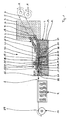
- FIG. 1 1 comprises two unwinding devices A, two feeders 3 and 4 for feeding respectively a plurality of monofilaments of two different types, not illustrated individually, but illustrated only by lines 5 and 6, a cleaning device R, as an essential component Coating device 7, a compacting device 8, a drying device 9 shown only schematically and finally a winding device 10 for winding the monofilament thread 2 on.
- the unwinding devices allow a twist-free unwinding of the bundles of single filaments, so that in particular an over-head unwinding is eliminated.
- the two feeders 3 and 4 are slightly curved tube bodies 11 and 12, through which the individual filaments, which are monofilaments, are guided in isolated form.
- the individual filaments are unrolled by another, not shown, but known from the prior art winding device without rotation.
- both bundles of monofilaments are passed through a bath or curtain of a cleaning liquid (primer) of a cleaning device R before being subsequently pretreated to the coating device.
- the coating device 7 is formed by a container 13, in which a bath of a flowable resin 14 is located, through which pass the respective plurality of individual filaments of the two types. Thus, a dip coating of all individual filaments takes place. Via a connection, not shown, a mirror 15 of the resin bath is kept constant, in particular the continuous consumption of the resin in the thread coating compensated.
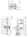
- the compacting device 8 which in the FIGS. 2a to 2c is shown separately in three views, consists of an inner nozzle 16 and a coaxially arranged outer nozzle 17. Both nozzles 16 and 17 are in the Figures 3a, 3b and 4a, 4b again shown in detail in different perspective views.
- the inner nozzle has a frustoconical outer surface 18 and a - having a smaller cone angle - inner lateral surface 19.
- the inner circumferential surface 19 defines an inner space 20 of the inner nozzle 16, wherein in the inner space 20 up to an opening cross section 22 arranged at a tip 21 of the inner nozzle 16, the compaction, i. radial compression, the majority of those individual filaments takes place, which later produce an inner zone of the thread 2.
- the outer nozzle 17 has a stepped cylindrical outer surface 23 and a frusto-conical inner surface whose cone angle is in turn greater than that Cone angle of the outer frusto-conical lateral surface 18 of the inner nozzle 16.
- an outlet cross-section 28 of the outer nozzle 17 is at the end of the compaction process before a monofilament thread 2, which has a relatively dense arrangement of the individual filaments in its cross section, wherein the spaces between the individual filaments are completely filled with resin 14 and have no gas inclusions.
- the outer single filaments wrap around the outer circumferential surface 18 of the inner nozzle 16.
- the outer single filaments form a closed ring which, viewed in cross-section, completely surrounds the individual filaments approximately circular in cross-section which exit from the inner nozzle 16 and form the later inner zone of the filament 2 ,
- the outer cone angle of the inner nozzle 16 is about 1.5 ° to 2.5 °, preferably 2.0 ° and the inner cone angle of the inner nozzle 16 about 10 ° to 15 °, preferably about 12 °.
- the inner cone angle of the outer nozzle is about 15 ° to 20 °, preferably about 18 °.
- the monofilament yarn 2 formed as described above is dried using microwave radiation and / or hot air convection or the like, i. the solvent of the resin 14 formed by water in the present case is removed from the latter, so that the viscosity increases, the adhesive property and thus the cohesion of the individual filaments is improved.
- it only takes place drying in the physical sense and no chemical crosslinking of the monomers of the resin 14th
- the thread 2 After leaving the drying device 9, the thread 2 is stabilized so far and so far has no "sticky" properties more that he on the winding device 10 on corresponding coils 29 can be wound.
- the individual filaments - in the present case both types - are not twisted together at any point of the manufacturing process. Throughout the manufacturing process, the parallel, ie unidirectional, alignment of all single filaments is maintained, as is the case for the finished filament 2 wound on the spool 29.
- FIGS. 1 and FIGS. 2 a to 2 c show that the inner nozzle 16 is fastened to a first nozzle carrier 30.
- the outer nozzle 17 is attached to a second nozzle carrier 31 and screwed with an externally threaded portion 32 in a cooperating internally threaded portion 33 of the nozzle carrier 31.
- a horizontal displacement of the outer nozzle 17 along the double arrow 35 can be achieved.
- both nozzle carriers 30, 31 are screwed to a base plate 36, wherein the base plate 36 is arranged on a bottom surface 37 of the container 13.
- the nozzles 16, 17, the nozzle carrier 30, 31 and the base plate 36 as well as the screws used for connection consist of stainless steel. The same applies to the container 13 and the tubular body 11 and 12 of the feeders 3 and 4.
- the inner nozzle 16 has, following its frustoconical front part, a tubular rear part which adjoins the front part at a step 38. With the rear part, which has an opening cross-section 39, the inner nozzle 16 can be used a correspondingly adapted extended bore portion 40 of a tubular nozzle holder 41, which in turn is connected to the nozzle carrier 30.
- a thread 2 whose inner zone, which is circular in cross-section, consists of approximately 100 to 2000 individual filaments of carbon (carbon).
- An outer zone which is annular in cross-section and arranged around the inner zone, in turn has approximately 100 to 2000 individual filaments.
- These can for example consist of glass or ceramic.
- the diameters of both filament types can be between about 5 ⁇ m and 25 ⁇ m, preferably between about 8 ⁇ m and 20 ⁇ m.
- the individual filaments of one type all have the same diameter, and all filament types may have the same diameter.
- the resin 14 in the present case consists of a silicone resin mixture.
- Particularly suitable is the silicone resin of the company. Wacker Chemie AG, Kunststoff, Germany, which is sold under the name "WS 40".
- the crosslinking of the silicone resin takes place at a later time, when the finished thread 2 is unwound from the bobbin 29 again and processed into a semifinished product or end product (textile fabric or three-dimensional structure) and thus the final shape of the part is fixed.
- the crosslinking temperature is above 140 ° C, preferably a pressure of about up to 500 N / mm 2 is applied.
- the further processing of the uncrosslinked thread 2 is not the subject of the present application.
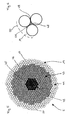
- the alternative thread 2 ' has a three-zone structure with respect to the yarn 2 produced with the device 1.
- An inner zone 42 is surrounded by a first outer zone 43 which is annular in cross-section and which is enclosed in turn radially outwards by a second outer zone 44 of annular cross-section.
- the individual filaments 45 of the inner zone are formed by carbon fibers, the individual filaments 46 of the first outer zone 43 made of basalt and the individual filaments 47 of the second outer zone 44 made of silicone. It should be noted that the representation of the individual filaments 45 to 47 is not to scale with respect to the number present in each zone.
- the thread 2 as a product of the device 1, preferably at least about 100 individual filaments are present in the inner zone 42.
- the two outer zones 43, 44 there are typically correspondingly more, ie between approximately 500 and 1500, depending on the selected layer thicknesses.
- the thread 2 ' like all threads produced by the method according to the invention, is characterized by a very high packing density of the individual filaments 45 to 47 in all three zones.
- Spaces 48 the in FIG. 6 are exemplified by three exemplary selected individual filaments 47, have in cross-section a typical gusset shape (triangle with curved sides).
- contact lines 49 or contact surfaces are thin intermediate layers of resin, whereby the strength of the composite of individual filaments 47 and resin for later crosslinking of the resin is improved.
- resin 14 is also in a limited by the dashed line 50 area around the individual filaments 47 around and also in the formed between adjacent individual filaments 47 gussets 51. Overall, the resin consumption at the inventive method or thread 2 and 2 'minimized.
- Aramid in particular para-aramid monofilament, is used in particular because of the high price, if the strength properties or the ratio of strength and mass is important (aerospace, security technology, etc.).
- Glass fiber is a cost effective material with satisfactory properties. If high temperature resistance is required, ceramic or basalt fibers may be used.
- Abrasion-resistant monofilaments are usually used in the outer zone, those with high tensile strength usually in the inner zone.
Landscapes
- Engineering & Computer Science (AREA)
- Mechanical Engineering (AREA)
- Textile Engineering (AREA)
- Chemical & Material Sciences (AREA)
- Composite Materials (AREA)
- Reinforced Plastic Materials (AREA)
- Laminated Bodies (AREA)
- Treatments For Attaching Organic Compounds To Fibrous Goods (AREA)
- Yarns And Mechanical Finishing Of Yarns Or Ropes (AREA)
- Moulding By Coating Moulds (AREA)
- Treatment Of Fiber Materials (AREA)
- Woven Fabrics (AREA)
- Coating Apparatus (AREA)
- Spinning Methods And Devices For Manufacturing Artificial Fibers (AREA)
- Application Of Or Painting With Fluid Materials (AREA)
- Manufacturing Of Multi-Layer Textile Fabrics (AREA)
Claims (12)
- Procédé de fabrication d'un fil (2, 2') qui possède une pluralité de filaments distincts (45, 46, 47) qui sont enrobés d'une résine (14) fluide, contenant un solvant et pouvant être réticulée par l'action d'au moins un paramètre physique et/ou un produit chimique, les filaments enrobés distincts (45, 46,, 47) étant ensuite compactés de manière à constituer un composite formé des filaments distincts (45, 46, 47) et de la résine (14) y adhérant et exempt d'inclusions gazeuses, composite duquel, pendant un processus de séchage, le solvant contenu dans la résine (14) est expulsé, le composite présent sous forme de fil monofilament (2, 2') étant ensuite enroulé en état non réticulé de la résine (14) et tous les filaments distincts étant maintenus en orientation parallèle pendant toutes les étapes opératoires précédentes, caractérisé en ce que les filaments distincts (45, 46, 47) sont chauffés avant enrobage avec la résine (14) à une température de 50 °C à 80 °C, les filaments distincts (45, 46, 47) étant enrobés en les plongeant dans un bain de résine (14).
- Procédé selon la revendication 1, caractérisé en ce que les filaments distincts (45, 46, 47) sont tirés en continu dans le bain.
- Procédé selon la revendication 1 ou 2, caractérisé en ce que le compactage se fait dans une buse (16, 17) à travers laquelle la pluralité d'éléments enrobés (45, 46, 47) sont tirés, un espace intérieur (20, 25) de la buse (16, 17) étant en forme de tronc conique, de sorte que, à la sortie des filaments distincts (45, 46, 47) compactés d'une section d'ouverture de la buse (16, 17), la résine excédentaire (14) est retenue dans l'espace intérieur (20, 25) de la buse (16, 17).
- Procédé selon une des revendications 1 à 3, caractérisé en ce que les filaments distincts (45, 46, 47) comprennent au moins un des types de filaments suivants :a) filaments de polymères synthétiques, en particulier d'aramide, de préférence de para-aramide,b) filaments de carbone,c) filaments de verre,d) filaments de minéraux, en particulier de basalte,e) filaments de métal (fil), en particulier d'acier.
- Procédé selon une des revendications 1 à 4, caractérisé en ce que les filaments distincts (45, 46, 47) ont un diamètre de l'ordre de 3 µm à 30 µm, de préférence de 4 µ à 20 µm, plus préférentiellement de 6 µm à 10 µm et/ou que le composite compacté a un diamètre de l'ordre de 150 µm à 10 mm, de préférence de 200 µm à 2 mm, plus préférentiellement de 250 µm à 1,0 mm et/ou que le fil monofilament séché a un diamètre de l'ordre de 120 µm à 10 mm, de préférence de 160 µm à 1,6 mm, plus préférentiellement de 200 µm à 0,9 mm.
- Procédé selon une des revendications 1 à 5, caractérisé en ce que le fil monofilament est composé d'un certain nombre de filaments distincts des intervalles suivants : 100 à 3000, de préférence 150 à 2000, plus préférentiellement de 200 à 1000.
- Procédé selon une des revendications 1 à 6, caractérisé en ce que la résine (14) est sélectionnée dans le groupe des types de résines suivants :a) résine de phénol-formaldéhyde,b) résine d'aminoplaste,c) résine époxyde,d) résine de polyester,e) résine d'ABS,f) résine de siliconeou d'un mélange d'au moins deux des types de résines précités.
- Procédé selon une des revendications 1 à 7, caractérisé en ce que la résine (14) présente, après séchage, une proportion de solvant, de préférence une proportion d'eau, comprise entre 10 % et 70 %, de préférence entre 20 % et 50 %, plus préférentiellement entre 30 % et 40 %.
- Procédé selon une des revendications 1 à 8, caractérisé en ce que le solvant est expulsé du composite enrobé et compacté par convection avec de l'air apporté de force et/ou par rayonnement électromagnétique, en particulier rayonnement infrarouge et/ou rayonnement infrarouge et rayonnement de micro-ondes, la température étant maintenue lors du processus de séchage de préférence dans la plage de 70 °C à 110 °C, de préférence de 80 °C à 100 °C.
- Procédé selon une des revendications 1 à 9, caractérisé en ce que les filaments distincts (45, 46, 47), avant enrobage avec la résine (14), sont chauffés à une température de 60 °C à 70 °C.
- Dispositif (1) de fabrication d'un fil (2) qui possède une pluralité de filaments distincts, comprenant- au moins un dispositif d'acheminement (3, 4) pour la pluralité de filaments distincts (45, 46, 47) orientés parallèlement les uns aux autres,- un dispositif d'enrobage (7) à l'aide duquel les filaments distincts peuvent être enrobés au niveau de leurs surfaces d'enveloppe d'une résine fluide (14) contenant un solvant et pouvant être réticulée par l'action d'au moins un paramètre physique et/ou d'un produit chimique,- un dispositif de compactage (8) qui permet de réduire la section transversale occupée par la pluralité de filaments distincts et la résine (14) y adhérant de manière à pouvoir créer un composite formé des filaments distincts et de la résine (14) qui les entoure et exempt d'inclusions gazeuses,- un dispositif de séchage (9) qui permet d'expulser le solvant contenu dans la résine (14) du composite compacté,- un dispositif d'enroulement (10) qui permet d'enrouler le composite séché en minimisant les tensions de manière à ce que les filaments distincts soient disposés sans torsion et- un moyen pour chauffer les filaments distincts (45, 46, 47) à une température de 50 °C à 80 °C en amont du dispositif d'enrobage (7),caractérisé en ce que- le dispositif d'enrobage (7) est un réceptacle (13) contenant un bain de résine (14) dans lequel la pluralité de filaments distincts peuvent être conduits individuellement.
- Dispositif selon la revendication 11, caractérisé en ce que le dispositif de compactage. (8) présente au moins une buse (16, 17) dont l'espace intérieur (20, 25) a une forme de tronc conique.
Applications Claiming Priority (3)
| Application Number | Priority Date | Filing Date | Title |
|---|---|---|---|
| DE200910019500 DE102009019500A1 (de) | 2009-05-04 | 2009-05-04 | Triangel Hybrid Zero Twist Filmament Verbund werkstoff |
| DE102009061031 | 2009-07-29 | ||
| PCT/EP2010/056038 WO2010128048A2 (fr) | 2009-05-04 | 2010-05-04 | Procédé et dispositif de fabrication d'un fil à partir d'une pluralité de monofilaments et fil monofilament ainsi fabriqué |
Publications (2)
| Publication Number | Publication Date |
|---|---|
| EP2427309A2 EP2427309A2 (fr) | 2012-03-14 |
| EP2427309B1 true EP2427309B1 (fr) | 2014-02-19 |
Family
ID=43050548
Family Applications (2)
| Application Number | Title | Priority Date | Filing Date |
|---|---|---|---|
| EP20100719324 Not-in-force EP2427323B9 (fr) | 2009-05-04 | 2010-05-04 | Procédé de fabrication d'un matériau composite renforcé par fibres |
| EP20100718574 Not-in-force EP2427309B1 (fr) | 2009-05-04 | 2010-05-04 | Procédé et dispositif de fabrication d'un fil à partir d'une pluralité de monofilaments |
Family Applications Before (1)
| Application Number | Title | Priority Date | Filing Date |
|---|---|---|---|
| EP20100719324 Not-in-force EP2427323B9 (fr) | 2009-05-04 | 2010-05-04 | Procédé de fabrication d'un matériau composite renforcé par fibres |
Country Status (9)
| Country | Link |
|---|---|
| US (3) | US20120121850A1 (fr) |
| EP (2) | EP2427323B9 (fr) |
| JP (2) | JP5730287B2 (fr) |
| CN (2) | CN102574302B (fr) |
| BR (2) | BRPI1014554A2 (fr) |
| CA (2) | CA2760971C (fr) |
| ES (2) | ES2464122T3 (fr) |
| RU (2) | RU2518476C2 (fr) |
| WO (2) | WO2010128048A2 (fr) |
Families Citing this family (36)
| Publication number | Priority date | Publication date | Assignee | Title |
|---|---|---|---|---|
| CN103142220B (zh) * | 2011-12-06 | 2016-04-27 | 深圳迈瑞生物医疗电子股份有限公司 | 血压袖带 |
| DE102012101295A1 (de) | 2012-02-17 | 2013-08-22 | Lff Composite Technology Gmbh | Faserverbundwerkstoff |
| US9370896B2 (en) | 2013-06-05 | 2016-06-21 | Markforged, Inc. | Methods for fiber reinforced additive manufacturing |
| US9186848B2 (en) | 2013-03-22 | 2015-11-17 | Markforged, Inc. | Three dimensional printing of composite reinforced structures |
| US10953609B1 (en) | 2013-03-22 | 2021-03-23 | Markforged, Inc. | Scanning print bed and part height in 3D printing |
| CA3121870A1 (fr) | 2013-03-22 | 2014-09-25 | Markforged, Inc. | Impression tridimensionnelle |
| US9579851B2 (en) | 2013-03-22 | 2017-02-28 | Markforged, Inc. | Apparatus for fiber reinforced additive manufacturing |
| US9156205B2 (en) * | 2013-03-22 | 2015-10-13 | Markforged, Inc. | Three dimensional printer with composite filament fabrication |
| US11237542B2 (en) | 2013-03-22 | 2022-02-01 | Markforged, Inc. | Composite filament 3D printing using complementary reinforcement formations |
| US9126365B1 (en) | 2013-03-22 | 2015-09-08 | Markforged, Inc. | Methods for composite filament fabrication in three dimensional printing |
| US9186846B1 (en) | 2013-03-22 | 2015-11-17 | Markforged, Inc. | Methods for composite filament threading in three dimensional printing |
| US11981069B2 (en) | 2013-03-22 | 2024-05-14 | Markforged, Inc. | Three dimensional printing of composite reinforced structures |
| US9694544B2 (en) | 2013-03-22 | 2017-07-04 | Markforged, Inc. | Methods for fiber reinforced additive manufacturing |
| KR101821162B1 (ko) * | 2013-07-05 | 2018-01-23 | 무라다기카이가부시끼가이샤 | 실 제조 장치 |
| US10982381B2 (en) | 2014-10-06 | 2021-04-20 | Natural Fiber Welding, Inc. | Methods, processes, and apparatuses for producing welded substrates |
| US10011931B2 (en) | 2014-10-06 | 2018-07-03 | Natural Fiber Welding, Inc. | Methods, processes, and apparatuses for producing dyed and welded substrates |
| SG10201502009XA (en) * | 2015-03-16 | 2016-01-28 | Ha Fee Ho | Pre-Impregnated Composite Material |
| BR112017020808B8 (pt) * | 2015-04-06 | 2024-02-15 | Dupont Nutrition Biosci Aps | Produto de leite fermentado e seu método de produção e uso de uma protease exógena subtilisina, protease serina protease, ou uma metaloprotease |
| US10099435B2 (en) * | 2015-06-04 | 2018-10-16 | Ford Global Technologies, Llc | Method of splitting fiber tows |
| MX2018010421A (es) | 2016-03-25 | 2019-05-20 | Natural Fiber Welding Inc | Metodos, procesos y aparatos para producir sustratos soldados. |
| CN109196149B (zh) | 2016-05-03 | 2021-10-15 | 天然纤维焊接股份有限公司 | 用于生产染色的焊接基质的方法、工艺和设备 |
| CN106435899B (zh) * | 2016-10-09 | 2019-03-29 | 宜宾纬络纺织有限公司 | 一种芯鞘型复合纱及其制备方法 |
| RU2643875C1 (ru) * | 2017-03-16 | 2018-02-06 | Павел Андреевич Еговцев | Композитные профильные элементы с сетчатой структурой (варианты) |
| RU2638335C1 (ru) * | 2017-03-23 | 2017-12-13 | Акционерное общество "ФПГ ЭНЕРГОКОНТРАКТ" | Термостойкий огнестойкий материал |
| CN106978667A (zh) * | 2017-04-24 | 2017-07-25 | 东莞易昌塑胶布业有限公司 | 一种网布制作方法 |
| TWI829660B (zh) | 2017-11-11 | 2024-01-21 | 美商天然纖維焊接股份有限公司 | 紗與熔接紗 |
| FR3085126B1 (fr) | 2018-08-27 | 2020-09-11 | Safran Nacelles | Procede de fabrication d'une preforme composite pour la fabrication d'un panneau composite a geometrie a double courbure |
| DE102019001585A1 (de) | 2019-03-08 | 2020-09-10 | Ralph Funck | Faserverbundstrebe |
| CN109914002B (zh) * | 2019-04-03 | 2022-01-04 | 平湖市三禾染整股份有限公司 | 一种纱线前处理工艺 |
| CH716120A1 (de) * | 2019-04-26 | 2020-10-30 | On Clouds Gmbh | Verfahren zur additiven Fertigung eines textilen Flächenprodukts. |
| WO2021118521A1 (fr) * | 2019-12-09 | 2021-06-17 | Thru Tubing Solutions, Inc. | Dispositifs de bouchage comportant des filaments revêtus d'un matériau gonflable |
| IT202000010243A1 (it) * | 2020-05-07 | 2021-11-07 | Fibre Net Holding S R L | Rete in materiale composito |
| CN114232218A (zh) * | 2021-12-27 | 2022-03-25 | 江西省安秀实业发展有限公司 | 一种包络型弹力无纺布及其制备装置和制备方法 |
| CN115305673A (zh) * | 2022-07-29 | 2022-11-08 | 海宁中创新材料科技有限公司 | 单丝表面涂层机构 |
| CN115583055B (zh) * | 2022-09-29 | 2025-08-15 | 上海电缆研究所有限公司 | 纤维增强复合材料的制造工艺及纤维增强复合材料 |
| WO2025107241A1 (fr) * | 2023-11-23 | 2025-05-30 | 香港纺织及成衣研发中心 | Procédé de préparation de textile sur la base d'une réticulation |
Family Cites Families (36)
| Publication number | Priority date | Publication date | Assignee | Title |
|---|---|---|---|---|
| JPS52120034A (en) * | 1976-03-31 | 1977-10-08 | Nippon Carbon Co Ltd | Gut for racket |
| GB2012623B (en) * | 1978-01-17 | 1982-07-07 | Secr Defence | Impregnation of filamentary material |
| DE2818386C2 (de) * | 1978-04-27 | 1982-03-11 | Fröhlich & Wolff GmbH, 3436 Hessisch-Lichtenau | Garn aus einem multifilen, synthetischen, polymeren Material und Verfahren zur Veredelung eines derartigen Garns |
| DE3038898C2 (de) * | 1980-10-15 | 1985-10-10 | Dyckerhoff & Widmann AG, 8000 München | Verfahren zum Erzeugen eines Korrosionsschutzes bei Litzen aus hochfesten Stahldrähten |
| US4419400A (en) * | 1981-10-26 | 1983-12-06 | Occidental Chemical Corporation | Pultruded reinforced phenolic resin products |
| US4643126A (en) * | 1984-11-21 | 1987-02-17 | The Budd Company | Method and apparatus for impregnating fiber strands |
| NL8501146A (nl) * | 1985-04-19 | 1986-11-17 | Philips Nv | Inrichting voor het bekleden van optische vezels. |
| JPS63275775A (ja) * | 1987-05-01 | 1988-11-14 | 東レ株式会社 | 樹脂コ−テイング繊維糸条の製造方法およびそのコ−テング装置 |
| KR890005310A (ko) * | 1987-09-17 | 1989-05-13 | 나까하라 노부유끼 | 섬유강화 복합수지 인발성형품(引拔成形品) 및 그의 제조방법 |
| US4870814A (en) * | 1988-04-29 | 1989-10-03 | Orscheln Co. | Process for manufacturing corrosion resistant cable |
| US5198281A (en) * | 1989-04-17 | 1993-03-30 | Georgia Tech Research Corporation | Non-woven flexible multiply towpreg fabric |
| JPH0633537B2 (ja) * | 1989-04-19 | 1994-05-02 | 天龍工業株式会社 | 繊維束 |
| JPH04192496A (ja) * | 1990-11-27 | 1992-07-10 | Mitsubishi Gas Chem Co Inc | 積層板類の製造法 |
| US5344689A (en) * | 1991-08-09 | 1994-09-06 | Kabushiki Kaisha Kobe Seiko Sho | Carbon fiber prepreg and carbon fiber reinforced resin composite |
| FR2685249B1 (fr) * | 1991-12-24 | 1994-02-11 | Snecma | Procede de fabrication d'une pale de soufflante en materiau composite et outillage de moulage. |
| JPH0649781A (ja) * | 1992-07-22 | 1994-02-22 | Mitsui Toatsu Chem Inc | 複合ヤーン |
| RU2082610C1 (ru) * | 1993-03-01 | 1997-06-27 | Обнинское научно-производственное объединение "Технология" | Способ изготовления многослойных профильных изделий из полимерных композиционных материалов |
| DE4417836C2 (de) * | 1994-05-20 | 1996-03-28 | Lignotock Gmbh | Verfahren zum Herstellen von Formteilen |
| DE19530020A1 (de) * | 1995-08-16 | 1997-02-20 | Menzolit Fibron Gmbh | Verfahren zum Herstellen eines Compounds aus einem Kunststoff mit fester Fasereinlage |
| ATE299427T1 (de) * | 1996-08-12 | 2005-07-15 | Owens Corning Fiberglass Corp | Chemische behandlung für fasern und drahtbeschichtete verbundwerkstoffstränge zum formen von faserverstärkten thermoplastischen verbundwerkstoffgegenständen |
| US6523578B1 (en) * | 1998-10-20 | 2003-02-25 | The Boeing Company | Composite prepreg material form with improved resistance to core crush and porosity |
| US6062014A (en) * | 1999-01-07 | 2000-05-16 | Yeh; Yueh-Jui | String for a racket |
| EP1094042A1 (fr) * | 1999-10-22 | 2001-04-25 | Art Trading Services SA | Imprégnation de fibres avec des polymères thermoplastiques ou thermodurcissables comme des liquides, comme émulsion ou suspension |
| US6713413B2 (en) * | 2000-01-03 | 2004-03-30 | Freudenberg Nonwovens Limited Partnership | Nonwoven buffing or polishing material having increased strength and dimensional stability |
| JP2003528224A (ja) * | 2000-03-20 | 2003-09-24 | ペー−デー・テク・フィル・ゲゼルシャフト・ミト・ベシュレンクテル・ハフツング・テヒニッシェ・フィラメンテ | ヤーンプレプレグ材の製造方法 |
| KR100358680B1 (ko) * | 2000-04-17 | 2002-10-30 | 주식회사 연산 | 폴의 피복 방법 및 그 방법에 의하여 제조된 폴 |
| US6893524B2 (en) * | 2003-01-24 | 2005-05-17 | Glastic Corporation | Method and apparatus for manufacturing a reinforcement |
| FR2854814A1 (fr) * | 2003-05-15 | 2004-11-19 | Cousin Composites | Corde synthetique pour raquette de tennis |
| JP2005059434A (ja) * | 2003-08-14 | 2005-03-10 | Shinwa Kk | 車輛の座席又はドア内面の表皮材及びその製造方法 |
| GB2409837B (en) * | 2004-01-10 | 2006-09-06 | Hexcel Composites Ltd | Fibre reinforced resin assembly |
| ES2391401T3 (es) * | 2004-03-31 | 2012-11-26 | Toho Tenax Europe Gmbh | Hilo impregnado con una resina epoxídica y su utilización para la producción de una preforma |
| US7527222B2 (en) * | 2004-04-06 | 2009-05-05 | The Boeing Company | Composite barrel sections for aircraft fuselages and other structures, and methods and systems for manufacturing such barrel sections |
| CN1775513A (zh) * | 2005-11-30 | 2006-05-24 | 东华大学 | 微波原位聚合长玻璃纤维增强abs复合材料的制备方法 |
| US7617667B2 (en) * | 2005-12-22 | 2009-11-17 | Pascale Industries, Inc. | Treatment of brittle, high-modulus yarns to yield improved processing characteristics |
| JP4231916B2 (ja) * | 2006-04-28 | 2009-03-04 | 日信工業株式会社 | 炭素繊維複合樹脂材料の製造方法 |
| KR100834974B1 (ko) * | 2007-01-29 | 2008-06-03 | 한국생산기술연구원 | 하이브리드 금속을 이용한 고속 정보통신용 디지털사의 제조방법 및 이에 의하여 제조된 디지털사 |
-
2010
- 2010-05-04 JP JP2012509014A patent/JP5730287B2/ja not_active Expired - Fee Related
- 2010-05-04 RU RU2011149246/04A patent/RU2518476C2/ru not_active IP Right Cessation
- 2010-05-04 CA CA2760971A patent/CA2760971C/fr not_active Expired - Fee Related
- 2010-05-04 CN CN201080027955.6A patent/CN102574302B/zh not_active Expired - Fee Related
- 2010-05-04 EP EP20100719324 patent/EP2427323B9/fr not_active Not-in-force
- 2010-05-04 CA CA2760974A patent/CA2760974C/fr not_active Expired - Fee Related
- 2010-05-04 BR BRPI1014554A patent/BRPI1014554A2/pt not_active IP Right Cessation
- 2010-05-04 ES ES10719324T patent/ES2464122T3/es active Active
- 2010-05-04 ES ES10718574T patent/ES2464365T3/es active Active
- 2010-05-04 RU RU2011149245/04A patent/RU2518378C2/ru not_active IP Right Cessation
- 2010-05-04 WO PCT/EP2010/056038 patent/WO2010128048A2/fr not_active Ceased
- 2010-05-04 EP EP20100718574 patent/EP2427309B1/fr not_active Not-in-force
- 2010-05-04 WO PCT/EP2010/056040 patent/WO2010128049A2/fr not_active Ceased
- 2010-05-04 CN CN201080027957.5A patent/CN102574336B/zh not_active Expired - Fee Related
- 2010-05-04 BR BRPI1013976A patent/BRPI1013976A2/pt not_active IP Right Cessation
- 2010-05-04 JP JP2012509013A patent/JP5744009B2/ja not_active Expired - Fee Related
-
2011
- 2011-11-04 US US13/373,134 patent/US20120121850A1/en not_active Abandoned
- 2011-11-04 US US13/373,136 patent/US8413415B2/en not_active Expired - Fee Related
-
2013
- 2013-11-06 US US14/073,435 patent/US20140304957A1/en not_active Abandoned
Also Published As
| Publication number | Publication date |
|---|---|
| CA2760974A1 (fr) | 2010-11-11 |
| CA2760971A1 (fr) | 2010-11-11 |
| CN102574336B (zh) | 2015-05-20 |
| BRPI1014554A2 (pt) | 2016-04-19 |
| JP2012526166A (ja) | 2012-10-25 |
| US20140304957A1 (en) | 2014-10-16 |
| CN102574302B (zh) | 2015-04-15 |
| RU2518476C2 (ru) | 2014-06-10 |
| RU2011149245A (ru) | 2013-06-10 |
| BRPI1013976A2 (pt) | 2016-04-05 |
| ES2464122T3 (es) | 2014-05-30 |
| WO2010128049A3 (fr) | 2011-02-24 |
| EP2427323B1 (fr) | 2014-02-19 |
| US20120144795A1 (en) | 2012-06-14 |
| EP2427309A2 (fr) | 2012-03-14 |
| CN102574302A (zh) | 2012-07-11 |
| EP2427323A2 (fr) | 2012-03-14 |
| CN102574336A (zh) | 2012-07-11 |
| JP2012526205A (ja) | 2012-10-25 |
| RU2011149246A (ru) | 2013-06-10 |
| CA2760971C (fr) | 2017-03-07 |
| US8413415B2 (en) | 2013-04-09 |
| CA2760974C (fr) | 2017-06-13 |
| WO2010128048A2 (fr) | 2010-11-11 |
| ES2464365T3 (es) | 2014-06-02 |
| RU2518378C2 (ru) | 2014-06-10 |
| WO2010128049A2 (fr) | 2010-11-11 |
| JP5744009B2 (ja) | 2015-07-01 |
| WO2010128048A3 (fr) | 2011-03-24 |
| US20120121850A1 (en) | 2012-05-17 |
| EP2427323B9 (fr) | 2014-11-26 |
| JP5730287B2 (ja) | 2015-06-10 |
Similar Documents
| Publication | Publication Date | Title |
|---|---|---|
| EP2427309B1 (fr) | Procédé et dispositif de fabrication d'un fil à partir d'une pluralité de monofilaments | |
| DE3715681C2 (de) | Verfahren und Vorrichtung zur Herstellung eines kabelförmigen Kunststoff-Verbundkörpers | |
| DE102015210735A1 (de) | Verfahren zur Herstellung eines Faser-Kunststoff-Verbunds, Verfahren zur Herstellung eines Laminats, Faser-Kunststoff-Verbund sowie Enderzeugnis | |
| WO2002066762A1 (fr) | Barre d'armature et son procede de production | |
| EP1042110B1 (fr) | Procede et dispositif pour l'impregnation de fibres | |
| WO2012098122A1 (fr) | Procédé de fabrication d'un dispositif à fibres en forme de flexible d'un élément composite renforcé par fibres et dispositif à fibres en forme de flexible | |
| DE102016210040A1 (de) | Verfahren zum Herstellen eines zumindest bereichsweise profilierten, faserverstärkten Kunststoffprofils, ein profiliertes, faserverstärktes Kunststoffprofil und seine Verwendung | |
| WO2018130561A1 (fr) | Profilé extrudé et procédé de fabrication d'un profilé extrudé | |
| DE102015100386A1 (de) | Bewehrungsstab aus Filamentverbund und Verfahren zu dessen Herstellung | |
| DE102013109170B3 (de) | Faserzuführvorrichtung | |
| EP3142843B1 (fr) | Procédé de production d'un tube d'amortisseur à partir d'un matériau composite renforcé par des fibres pour amortisseur de vibrations | |
| DE2036513C3 (de) | Verfahren zur Herstellung rotationssymmetrischer Hohlkörper aus glasfaserverstärkten Kunststoffen | |
| DE2835401C2 (de) | Verfahren und Vorrichtung zur Herstellung von Hochdruckschläuchen | |
| DE102015209535A1 (de) | Verfahren und Vorrichtung zur Herstellung eines Faserhalbzeugs, Faserhalbzeug und Verfahren zur Herstellung eines faserverstärkten Kunststoffbauteils | |
| EP3038732B1 (fr) | Matériau filtrant, élément filtrant et procédé pour produire un matériau filtrant | |
| DE102011055285B3 (de) | Verfahren zum Herstellen eines Wickelprodukts und Wickelprodukt | |
| DE2304049A1 (de) | Chenille-garn sowie verfahren und vorrichtung zu seiner herstellung | |
| DE102010008633A1 (de) | Herstellungsverfahren eines winkelstarren Körpers | |
| EP1930608B1 (fr) | Cylindre avec une enveloppe tubulaire | |
| DE102014105795A1 (de) | Textiles Flächengebilde | |
| DE1753803A1 (de) | Verfahren zur herstellung eines verstaerkten kunststoffrohres | |
| EP3257663A1 (fr) | Procédé de fabrication de semi-produits pour éléments structuraux composites fibres/plastique | |
| DE102015208221A1 (de) | Verfahren zur Herstellung eines Faser-Kunststoff-Verbunds, Faser-Kunststoff-Verbund sowie Vorrichtung zur Herstellung eines Faser-Kunststoff-Verbunds | |
| DE102021126904A1 (de) | Endlosfaserverstärkter 3D-Druck durch induktives Beheizen | |
| DE102011083649A1 (de) | Verfahren zum Tränken eines endlosen Faserwerkstoffs |
Legal Events
| Date | Code | Title | Description |
|---|---|---|---|
| PUAI | Public reference made under article 153(3) epc to a published international application that has entered the european phase |
Free format text: ORIGINAL CODE: 0009012 |
|
| 17P | Request for examination filed |
Effective date: 20111129 |
|
| AK | Designated contracting states |
Kind code of ref document: A2 Designated state(s): AL AT BE BG CH CY CZ DE DK EE ES FI FR GB GR HR HU IE IS IT LI LT LU LV MC MK MT NL NO PL PT RO SE SI SK SM TR |
|
| DAX | Request for extension of the european patent (deleted) | ||
| 17Q | First examination report despatched |
Effective date: 20120928 |
|
| GRAP | Despatch of communication of intention to grant a patent |
Free format text: ORIGINAL CODE: EPIDOSNIGR1 |
|
| INTG | Intention to grant announced |
Effective date: 20131028 |
|
| GRAS | Grant fee paid |
Free format text: ORIGINAL CODE: EPIDOSNIGR3 |
|
| GRAA | (expected) grant |
Free format text: ORIGINAL CODE: 0009210 |
|
| AK | Designated contracting states |
Kind code of ref document: B1 Designated state(s): AL AT BE BG CH CY CZ DE DK EE ES FI FR GB GR HR HU IE IS IT LI LT LU LV MC MK MT NL NO PL PT RO SE SI SK SM TR |
|
| REG | Reference to a national code |
Ref country code: GB Ref legal event code: FG4D Free format text: NOT ENGLISH |
|
| REG | Reference to a national code |
Ref country code: CH Ref legal event code: EP |
|
| REG | Reference to a national code |
Ref country code: AT Ref legal event code: REF Ref document number: 652720 Country of ref document: AT Kind code of ref document: T Effective date: 20140315 |
|
| REG | Reference to a national code |
Ref country code: DE Ref legal event code: R096 Ref document number: 502010006117 Country of ref document: DE Effective date: 20140403 |
|
| REG | Reference to a national code |
Ref country code: IE Ref legal event code: FG4D Free format text: LANGUAGE OF EP DOCUMENT: GERMAN |
|
| REG | Reference to a national code |
Ref country code: ES Ref legal event code: FG2A Ref document number: 2464365 Country of ref document: ES Kind code of ref document: T3 Effective date: 20140602 |
|
| REG | Reference to a national code |
Ref country code: NL Ref legal event code: VDEP Effective date: 20140219 |
|
| REG | Reference to a national code |
Ref country code: LT Ref legal event code: MG4D |
|
| PG25 | Lapsed in a contracting state [announced via postgrant information from national office to epo] |
Ref country code: LT Free format text: LAPSE BECAUSE OF FAILURE TO SUBMIT A TRANSLATION OF THE DESCRIPTION OR TO PAY THE FEE WITHIN THE PRESCRIBED TIME-LIMIT Effective date: 20140219 Ref country code: IS Free format text: LAPSE BECAUSE OF FAILURE TO SUBMIT A TRANSLATION OF THE DESCRIPTION OR TO PAY THE FEE WITHIN THE PRESCRIBED TIME-LIMIT Effective date: 20140619 Ref country code: NO Free format text: LAPSE BECAUSE OF FAILURE TO SUBMIT A TRANSLATION OF THE DESCRIPTION OR TO PAY THE FEE WITHIN THE PRESCRIBED TIME-LIMIT Effective date: 20140519 |
|
| PG25 | Lapsed in a contracting state [announced via postgrant information from national office to epo] |
Ref country code: FI Free format text: LAPSE BECAUSE OF FAILURE TO SUBMIT A TRANSLATION OF THE DESCRIPTION OR TO PAY THE FEE WITHIN THE PRESCRIBED TIME-LIMIT Effective date: 20140219 Ref country code: PT Free format text: LAPSE BECAUSE OF FAILURE TO SUBMIT A TRANSLATION OF THE DESCRIPTION OR TO PAY THE FEE WITHIN THE PRESCRIBED TIME-LIMIT Effective date: 20140619 Ref country code: SE Free format text: LAPSE BECAUSE OF FAILURE TO SUBMIT A TRANSLATION OF THE DESCRIPTION OR TO PAY THE FEE WITHIN THE PRESCRIBED TIME-LIMIT Effective date: 20140219 Ref country code: CY Free format text: LAPSE BECAUSE OF FAILURE TO SUBMIT A TRANSLATION OF THE DESCRIPTION OR TO PAY THE FEE WITHIN THE PRESCRIBED TIME-LIMIT Effective date: 20140219 Ref country code: NL Free format text: LAPSE BECAUSE OF FAILURE TO SUBMIT A TRANSLATION OF THE DESCRIPTION OR TO PAY THE FEE WITHIN THE PRESCRIBED TIME-LIMIT Effective date: 20140219 |
|
| PG25 | Lapsed in a contracting state [announced via postgrant information from national office to epo] |
Ref country code: HR Free format text: LAPSE BECAUSE OF FAILURE TO SUBMIT A TRANSLATION OF THE DESCRIPTION OR TO PAY THE FEE WITHIN THE PRESCRIBED TIME-LIMIT Effective date: 20140219 Ref country code: LV Free format text: LAPSE BECAUSE OF FAILURE TO SUBMIT A TRANSLATION OF THE DESCRIPTION OR TO PAY THE FEE WITHIN THE PRESCRIBED TIME-LIMIT Effective date: 20140219 |
|
| PG25 | Lapsed in a contracting state [announced via postgrant information from national office to epo] |
Ref country code: DK Free format text: LAPSE BECAUSE OF FAILURE TO SUBMIT A TRANSLATION OF THE DESCRIPTION OR TO PAY THE FEE WITHIN THE PRESCRIBED TIME-LIMIT Effective date: 20140219 Ref country code: RO Free format text: LAPSE BECAUSE OF FAILURE TO SUBMIT A TRANSLATION OF THE DESCRIPTION OR TO PAY THE FEE WITHIN THE PRESCRIBED TIME-LIMIT Effective date: 20140219 Ref country code: EE Free format text: LAPSE BECAUSE OF FAILURE TO SUBMIT A TRANSLATION OF THE DESCRIPTION OR TO PAY THE FEE WITHIN THE PRESCRIBED TIME-LIMIT Effective date: 20140219 Ref country code: CZ Free format text: LAPSE BECAUSE OF FAILURE TO SUBMIT A TRANSLATION OF THE DESCRIPTION OR TO PAY THE FEE WITHIN THE PRESCRIBED TIME-LIMIT Effective date: 20140219 |
|
| REG | Reference to a national code |
Ref country code: DE Ref legal event code: R097 Ref document number: 502010006117 Country of ref document: DE |
|
| PG25 | Lapsed in a contracting state [announced via postgrant information from national office to epo] |
Ref country code: PL Free format text: LAPSE BECAUSE OF FAILURE TO SUBMIT A TRANSLATION OF THE DESCRIPTION OR TO PAY THE FEE WITHIN THE PRESCRIBED TIME-LIMIT Effective date: 20140219 Ref country code: SK Free format text: LAPSE BECAUSE OF FAILURE TO SUBMIT A TRANSLATION OF THE DESCRIPTION OR TO PAY THE FEE WITHIN THE PRESCRIBED TIME-LIMIT Effective date: 20140219 |
|
| PLBE | No opposition filed within time limit |
Free format text: ORIGINAL CODE: 0009261 |
|
| STAA | Information on the status of an ep patent application or granted ep patent |
Free format text: STATUS: NO OPPOSITION FILED WITHIN TIME LIMIT |
|
| PG25 | Lapsed in a contracting state [announced via postgrant information from national office to epo] |
Ref country code: LU Free format text: LAPSE BECAUSE OF FAILURE TO SUBMIT A TRANSLATION OF THE DESCRIPTION OR TO PAY THE FEE WITHIN THE PRESCRIBED TIME-LIMIT Effective date: 20140504 |
|
| REG | Reference to a national code |
Ref country code: CH Ref legal event code: PL |
|
| 26N | No opposition filed |
Effective date: 20141120 |
|
| PG25 | Lapsed in a contracting state [announced via postgrant information from national office to epo] |
Ref country code: LI Free format text: LAPSE BECAUSE OF NON-PAYMENT OF DUE FEES Effective date: 20140531 Ref country code: MC Free format text: LAPSE BECAUSE OF FAILURE TO SUBMIT A TRANSLATION OF THE DESCRIPTION OR TO PAY THE FEE WITHIN THE PRESCRIBED TIME-LIMIT Effective date: 20140219 Ref country code: CH Free format text: LAPSE BECAUSE OF NON-PAYMENT OF DUE FEES Effective date: 20140531 |
|
| REG | Reference to a national code |
Ref country code: IE Ref legal event code: MM4A |
|
| REG | Reference to a national code |
Ref country code: DE Ref legal event code: R097 Ref document number: 502010006117 Country of ref document: DE Effective date: 20141120 |
|
| PG25 | Lapsed in a contracting state [announced via postgrant information from national office to epo] |
Ref country code: IE Free format text: LAPSE BECAUSE OF NON-PAYMENT OF DUE FEES Effective date: 20140504 |
|
| PG25 | Lapsed in a contracting state [announced via postgrant information from national office to epo] |
Ref country code: SI Free format text: LAPSE BECAUSE OF FAILURE TO SUBMIT A TRANSLATION OF THE DESCRIPTION OR TO PAY THE FEE WITHIN THE PRESCRIBED TIME-LIMIT Effective date: 20140219 |
|
| PG25 | Lapsed in a contracting state [announced via postgrant information from national office to epo] |
Ref country code: MT Free format text: LAPSE BECAUSE OF FAILURE TO SUBMIT A TRANSLATION OF THE DESCRIPTION OR TO PAY THE FEE WITHIN THE PRESCRIBED TIME-LIMIT Effective date: 20140219 |
|
| PG25 | Lapsed in a contracting state [announced via postgrant information from national office to epo] |
Ref country code: SM Free format text: LAPSE BECAUSE OF FAILURE TO SUBMIT A TRANSLATION OF THE DESCRIPTION OR TO PAY THE FEE WITHIN THE PRESCRIBED TIME-LIMIT Effective date: 20140219 |
|
| REG | Reference to a national code |
Ref country code: FR Ref legal event code: PLFP Year of fee payment: 7 |
|
| PG25 | Lapsed in a contracting state [announced via postgrant information from national office to epo] |
Ref country code: GR Free format text: LAPSE BECAUSE OF FAILURE TO SUBMIT A TRANSLATION OF THE DESCRIPTION OR TO PAY THE FEE WITHIN THE PRESCRIBED TIME-LIMIT Effective date: 20140520 Ref country code: BG Free format text: LAPSE BECAUSE OF FAILURE TO SUBMIT A TRANSLATION OF THE DESCRIPTION OR TO PAY THE FEE WITHIN THE PRESCRIBED TIME-LIMIT Effective date: 20140219 |
|
| PG25 | Lapsed in a contracting state [announced via postgrant information from national office to epo] |
Ref country code: TR Free format text: LAPSE BECAUSE OF FAILURE TO SUBMIT A TRANSLATION OF THE DESCRIPTION OR TO PAY THE FEE WITHIN THE PRESCRIBED TIME-LIMIT Effective date: 20140219 Ref country code: HU Free format text: LAPSE BECAUSE OF FAILURE TO SUBMIT A TRANSLATION OF THE DESCRIPTION OR TO PAY THE FEE WITHIN THE PRESCRIBED TIME-LIMIT; INVALID AB INITIO Effective date: 20100504 Ref country code: BE Free format text: LAPSE BECAUSE OF FAILURE TO SUBMIT A TRANSLATION OF THE DESCRIPTION OR TO PAY THE FEE WITHIN THE PRESCRIBED TIME-LIMIT Effective date: 20140531 |
|
| PGFP | Annual fee paid to national office [announced via postgrant information from national office to epo] |
Ref country code: ES Payment date: 20160627 Year of fee payment: 7 |
|
| PGFP | Annual fee paid to national office [announced via postgrant information from national office to epo] |
Ref country code: AT Payment date: 20160525 Year of fee payment: 7 |
|
| PGFP | Annual fee paid to national office [announced via postgrant information from national office to epo] |
Ref country code: IT Payment date: 20170523 Year of fee payment: 8 |
|
| PGFP | Annual fee paid to national office [announced via postgrant information from national office to epo] |
Ref country code: GB Payment date: 20170728 Year of fee payment: 8 |
|
| REG | Reference to a national code |
Ref country code: FR Ref legal event code: PLFP Year of fee payment: 8 |
|
| REG | Reference to a national code |
Ref country code: AT Ref legal event code: MM01 Ref document number: 652720 Country of ref document: AT Kind code of ref document: T Effective date: 20170504 |
|
| PG25 | Lapsed in a contracting state [announced via postgrant information from national office to epo] |
Ref country code: AT Free format text: LAPSE BECAUSE OF NON-PAYMENT OF DUE FEES Effective date: 20170504 |
|
| PGFP | Annual fee paid to national office [announced via postgrant information from national office to epo] |
Ref country code: FR Payment date: 20171127 Year of fee payment: 8 |
|
| PG25 | Lapsed in a contracting state [announced via postgrant information from national office to epo] |
Ref country code: MK Free format text: LAPSE BECAUSE OF FAILURE TO SUBMIT A TRANSLATION OF THE DESCRIPTION OR TO PAY THE FEE WITHIN THE PRESCRIBED TIME-LIMIT Effective date: 20140219 |
|
| REG | Reference to a national code |
Ref country code: ES Ref legal event code: FD2A Effective date: 20180629 |
|
| PG25 | Lapsed in a contracting state [announced via postgrant information from national office to epo] |
Ref country code: ES Free format text: LAPSE BECAUSE OF NON-PAYMENT OF DUE FEES Effective date: 20170505 |
|
| PG25 | Lapsed in a contracting state [announced via postgrant information from national office to epo] |
Ref country code: AL Free format text: LAPSE BECAUSE OF FAILURE TO SUBMIT A TRANSLATION OF THE DESCRIPTION OR TO PAY THE FEE WITHIN THE PRESCRIBED TIME-LIMIT Effective date: 20140219 |
|
| GBPC | Gb: european patent ceased through non-payment of renewal fee |
Effective date: 20180504 |
|
| PG25 | Lapsed in a contracting state [announced via postgrant information from national office to epo] |
Ref country code: GB Free format text: LAPSE BECAUSE OF NON-PAYMENT OF DUE FEES Effective date: 20180504 Ref country code: IT Free format text: LAPSE BECAUSE OF NON-PAYMENT OF DUE FEES Effective date: 20180504 Ref country code: FR Free format text: LAPSE BECAUSE OF NON-PAYMENT OF DUE FEES Effective date: 20180531 |
|
| PGFP | Annual fee paid to national office [announced via postgrant information from national office to epo] |
Ref country code: DE Payment date: 20190531 Year of fee payment: 10 |
|
| REG | Reference to a national code |
Ref country code: DE Ref legal event code: R119 Ref document number: 502010006117 Country of ref document: DE |
|
| PG25 | Lapsed in a contracting state [announced via postgrant information from national office to epo] |
Ref country code: DE Free format text: LAPSE BECAUSE OF NON-PAYMENT OF DUE FEES Effective date: 20201201 |