EP2432026A1 - Fotovoltaik-Anlage mit Schutz gegen Stromschlaggefahren im Falle eines Brands, und Sicherheitsschaltkasten für eine solche Anlage - Google Patents
Fotovoltaik-Anlage mit Schutz gegen Stromschlaggefahren im Falle eines Brands, und Sicherheitsschaltkasten für eine solche Anlage Download PDFInfo
- Publication number
- EP2432026A1 EP2432026A1 EP10010036A EP10010036A EP2432026A1 EP 2432026 A1 EP2432026 A1 EP 2432026A1 EP 10010036 A EP10010036 A EP 10010036A EP 10010036 A EP10010036 A EP 10010036A EP 2432026 A1 EP2432026 A1 EP 2432026A1
- Authority
- EP
- European Patent Office
- Prior art keywords
- photovoltaic
- voltage
- panels
- switches
- relays
- Prior art date
- Legal status (The legal status is an assumption and is not a legal conclusion. Google has not performed a legal analysis and makes no representation as to the accuracy of the status listed.)
- Withdrawn
Links
Images


Classifications
-
- H—ELECTRICITY
- H10—SEMICONDUCTOR DEVICES; ELECTRIC SOLID-STATE DEVICES NOT OTHERWISE PROVIDED FOR
- H10F—INORGANIC SEMICONDUCTOR DEVICES SENSITIVE TO INFRARED RADIATION, LIGHT, ELECTROMAGNETIC RADIATION OF SHORTER WAVELENGTH OR CORPUSCULAR RADIATION
- H10F77/00—Constructional details of devices covered by this subclass
- H10F77/95—Circuit arrangements
- H10F77/953—Circuit arrangements for devices having potential barriers
- H10F77/955—Circuit arrangements for devices having potential barriers for photovoltaic devices
-
- H—ELECTRICITY
- H02—GENERATION; CONVERSION OR DISTRIBUTION OF ELECTRIC POWER
- H02J—ELECTRIC POWER NETWORKS; CIRCUIT ARRANGEMENTS OR SYSTEMS FOR SUPPLYING OR DISTRIBUTING ELECTRIC POWER; SYSTEMS FOR STORING ELECTRIC ENERGY
- H02J3/00—Circuit arrangements for AC mains or AC distribution networks
- H02J3/38—Arrangements for feeding a single network from two or more generators or sources in parallel; Arrangements for feeding already energised networks from additional generators or sources in parallel
- H02J3/381—Dispersed generators
-
- H—ELECTRICITY
- H02—GENERATION; CONVERSION OR DISTRIBUTION OF ELECTRIC POWER
- H02J—ELECTRIC POWER NETWORKS; CIRCUIT ARRANGEMENTS OR SYSTEMS FOR SUPPLYING OR DISTRIBUTING ELECTRIC POWER; SYSTEMS FOR STORING ELECTRIC ENERGY
- H02J2101/00—Supply or distribution of decentralised, dispersed or local electric power generation
- H02J2101/20—Dispersed power generation using renewable energy sources
- H02J2101/22—Solar energy
- H02J2101/24—Photovoltaics
-
- Y—GENERAL TAGGING OF NEW TECHNOLOGICAL DEVELOPMENTS; GENERAL TAGGING OF CROSS-SECTIONAL TECHNOLOGIES SPANNING OVER SEVERAL SECTIONS OF THE IPC; TECHNICAL SUBJECTS COVERED BY FORMER USPC CROSS-REFERENCE ART COLLECTIONS [XRACs] AND DIGESTS
- Y02—TECHNOLOGIES OR APPLICATIONS FOR MITIGATION OR ADAPTATION AGAINST CLIMATE CHANGE
- Y02B—CLIMATE CHANGE MITIGATION TECHNOLOGIES RELATED TO BUILDINGS, e.g. HOUSING, HOUSE APPLIANCES OR RELATED END-USER APPLICATIONS
- Y02B10/00—Integration of renewable energy sources in buildings
- Y02B10/10—Photovoltaic [PV]
-
- Y—GENERAL TAGGING OF NEW TECHNOLOGICAL DEVELOPMENTS; GENERAL TAGGING OF CROSS-SECTIONAL TECHNOLOGIES SPANNING OVER SEVERAL SECTIONS OF THE IPC; TECHNICAL SUBJECTS COVERED BY FORMER USPC CROSS-REFERENCE ART COLLECTIONS [XRACs] AND DIGESTS
- Y02—TECHNOLOGIES OR APPLICATIONS FOR MITIGATION OR ADAPTATION AGAINST CLIMATE CHANGE
- Y02E—REDUCTION OF GREENHOUSE GAS [GHG] EMISSIONS, RELATED TO ENERGY GENERATION, TRANSMISSION OR DISTRIBUTION
- Y02E10/00—Energy generation through renewable energy sources
- Y02E10/50—Photovoltaic [PV] energy
- Y02E10/56—Power conversion systems, e.g. maximum power point trackers
Definitions
- a photovoltaic installation includes a number of photovoltaic panels that convert light into electricity.
- Photovoltaic installations are currently mainly on the roofs of dwellings or buildings, either in roof integration or superimposed.
- Each photovoltaic panel is characterized by an electric power and a DC output voltage, also called DC current, typically a relatively low voltage, for example 30 volts.
- Photovoltaic installations are usually connected to the electricity distribution network.
- This transformation is done at the level of the inverter.
- Photovoltaic panels are usually connected in series on an electrical supply cable to connect the photovoltaic panels to the inverter.
- the power cable is powered by 180 Volts DC, which is a potentially dangerous voltage for a person in case of contact with the electrical wires of the cable. power.
- the panels produce electricity and the power cable remains energized, even if the central switch of the network breaker panel is cut.
- the object of the invention is to avoid the above-mentioned drawbacks and to provide a photovoltaic installation which gives greater security to the firefighters.
- firefighters may switch off the switches to isolate the DC power cable from the PV panels.
- the power cable is no longer powered and the maximum DC voltage present in the photovoltaic system is limited to the DC voltage of a single photovoltaic panel in the case of an individual connection or to the resulting DC voltage in case of a connection per group of panels.
- the photovoltaic panels are individually connected to the power cable via a said switch.
- the maximum voltage is then limited to the maximum voltage of each of the individual panels, which is for example 30 Volts DC and which does not constitute a danger in the event of an electrocution.
- the switches are preferably bipolar switches so that the two + and - terminals of the panels can be completely isolated from the power cable.
- the switches are preferably normally open type relays which are connected to a control signal for closing the relays in the event of normal operation of the photovoltaic system, the control signal being able to be switched off in the event of a fire to open the relays. eg via a safety disconnect located near the circuit breaker board.
- the switches are embedded in a sealed housing and optionally sealed in a cured resin to protect the switches from the weather and vandalism.
- the photovoltaic installation can advantageously be provided with a display for displaying the voltage present on the DC supply cable.
- the invention also relates to a security box for a photovoltaic installation as described above which comprises a number of normally open-type relays whose input of each of these relays is provided for the individual connection of a photovoltaic panel or a panel. a group of photovoltaic panels with DC voltage limited to a maximum value and whose outputs are interconnected in series and are provided for connection to a DC power cable and that the relays are provided with a connection for connection to a control signal to close the relays.
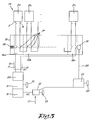
- the installation 1 according to the state of the art represented in the figure 1 is composed of a number of photovoltaic panels 2, including panels with reference 2a, 2b, ... 2n, which are for example mounted on the roof of a building.
- Each panel 2 is characterized by a voltage VDC between the positive terminal 3 and the negative terminal 4 of the panel 2, respectively the voltages VDCa, VDCb, ..., VDCn.
- the photovoltaic panels are connected together in series, that is to say that the negative terminal of a panel 2 is connected via an electrical wire 5 with the positive terminal of the next panel.
- the set of photovoltaic panels 2 connected in series is connected to a power cable 6 with two electric wires 7.
- This cable 6 is connected to an inverter 8 via a disconnector 9 which can isolate the inverter 8 from the power cable 6 by means of a handle 10.
- the inverter 8 is in turn connected to the electricity distribution network 11 via a circuit breaker board 12, which is provided with a handle 13 to be able to cut off the supply of the network 11.
- the power cable 6 is under a voltage VDC which is the sum of the voltages VDCa, VDCb, ... VDCn connected panels.
- the voltage on the cable 6 will be 180 Volt DC.
- the inverter 8 transforms the direct current coming from the power supply cable 6 into a AC current compatible with the standards of the network 11, for example 220 Volt AV, 50 Hz.
- the relatively high voltage on the power cable 6 poses a problem in the event of fire during the day since the cable 6 remains permanently under high voltage as the photovoltaic panels are exposed to daylight.
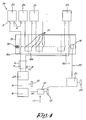
- the installation 14 according to the invention as represented in the figure 2 , comprises a security box 15 which comprises as many bipolar switches 16 as there are photovoltaic panels 2.
- the housing is preferably a sealed housing and the switches 16 are arbitrarily sealed in a resin.
- the photovoltaic panels 2 are connected to the input terminals of the switches 16 in such a way that each of the panels 2 is connected individually to one of the switches 16.
- the output terminals of the switches 17 are connected in series on the DC power cable 6 connected to the disconnector 9 and to the inverter 8 as before.
- the switches 17 are preferably normally open type relays as schematically represented in the figures 2 and 3 , at rest the contacts 17 between the inlet and the outlet are held in the open position by a return spring 18 as in the situation of the figure 3 .
- a safety disconnector 21 makes it possible to cut off the control signal 20 by means of a handle 22 for example in order to be able to open the relays 16 if necessary to isolate the panels 2 of the power cable 6.
- the safety disconnector 21 is preferably located at a location near the inverter 8 and therefore easily accessible for firefighters.
- the installation 14 is optionally provided with a display 23 for displaying the voltage on the DC power cable 6, this display 23 being preferably located near the circuit breaker board 12 of the network 11 and near the safety disconnector 21.
- the safety disconnector 21 is closed to switch the control signal 20 to the coil 19 of the relay-switches 16 to close the contacts 17 of the relays 16 as shown in the situation of the figure 2 .
- the voltage transferred by the cable 6 to the inverter 8 is exactly the same as in the conventional situation of the figure 1 , the panels 2 being connected in series in both cases.
- the fire-fighters can cut off the control signal 20 by actuating the handle 22 of the safety disconnector 22.
- Firefighters can also easily control the absence of any voltage on the display 23.
- the maximum voltage present in this part of the installation 14 is the maximum voltage of each of the panels.
- the maximum voltage is therefore 30 Volt DC, which poses no danger for the firefighters during the extinguishing work since these 30 Volt DC are sufficiently far from the danger threshold of 100 DC Volt.
- relay block with a single control coil 19 can be replaced by individual relays each with its own control coil.
- the control of the switches need not be a command as described, but can alternatively be replaced by manual control; by a remote control; by manual control; by automatic control by means of a fire detector or by means of a smoke detector; or by other types of command.
- the figure 4 shows an alternative connection of the photovoltaic panels on the input of the switches 16 of the housing 15.
- the photovoltaic panels 2a and 2b are grouped in series and connected as such on a single switch 2a, while the other panels 2 are always individually connected to the contactors 16. In this way we can save on the number of switches 16 .
- the resulting voltage of the panel group 2a and 2b on the contactor terminals is VDCa + VDCb, that is to say 60 Volt DC for panels of 30 Volt DC, while the voltage on the terminals of the other contactors 16 is 30 Volt DC.
- the maximum DC voltage in the installation will be 60 Volt DC, which is still far from the danger threshold of 100 Volt DC.
- the installer must look for a situation in which the maximum value of the DC voltage in the photovoltaic installation is 100 Volt DC, or better still 50 DC, or even better 30 Volt DC.
Landscapes
- Engineering & Computer Science (AREA)
- Power Engineering (AREA)
- Photovoltaic Devices (AREA)
Priority Applications (1)
| Application Number | Priority Date | Filing Date | Title |
|---|---|---|---|
| EP10010036A EP2432026A1 (de) | 2010-09-21 | 2010-09-21 | Fotovoltaik-Anlage mit Schutz gegen Stromschlaggefahren im Falle eines Brands, und Sicherheitsschaltkasten für eine solche Anlage |
Applications Claiming Priority (1)
| Application Number | Priority Date | Filing Date | Title |
|---|---|---|---|
| EP10010036A EP2432026A1 (de) | 2010-09-21 | 2010-09-21 | Fotovoltaik-Anlage mit Schutz gegen Stromschlaggefahren im Falle eines Brands, und Sicherheitsschaltkasten für eine solche Anlage |
Publications (1)
| Publication Number | Publication Date |
|---|---|
| EP2432026A1 true EP2432026A1 (de) | 2012-03-21 |
Family
ID=43825243
Family Applications (1)
| Application Number | Title | Priority Date | Filing Date |
|---|---|---|---|
| EP10010036A Withdrawn EP2432026A1 (de) | 2010-09-21 | 2010-09-21 | Fotovoltaik-Anlage mit Schutz gegen Stromschlaggefahren im Falle eines Brands, und Sicherheitsschaltkasten für eine solche Anlage |
Country Status (1)
| Country | Link |
|---|---|
| EP (1) | EP2432026A1 (de) |
Cited By (3)
| Publication number | Priority date | Publication date | Assignee | Title |
|---|---|---|---|---|
| FR3027749A1 (fr) * | 2014-10-23 | 2016-04-29 | Patrice Georges Gaston Antoine Creuzot | Dispositif de mise en securite electrique d'une installation de panneaux photovoltaiques par reduction des tensions electriques |
| JP2016135016A (ja) * | 2015-01-20 | 2016-07-25 | 日東工業株式会社 | 太陽光発電システム |
| CN108867909A (zh) * | 2018-08-09 | 2018-11-23 | 国家能源投资集团有限责任公司 | 光伏系统 |
Citations (8)
| Publication number | Priority date | Publication date | Assignee | Title |
|---|---|---|---|---|
| EP1039361A1 (de) * | 1999-03-24 | 2000-09-27 | Kaneka Corporation | Photovoltaisches Generatorsystem, Verdrahtungsanordnung für photvoltaisches Generatorsystem und Verdrahtungsstruktur dafür |
| US20010023703A1 (en) * | 2000-02-29 | 2001-09-27 | Hiroshi Kondo | Solar power generation apparatus and control method therefor |
| DE202006007613U1 (de) * | 2006-05-11 | 2006-08-17 | Beck, Manfred | Fotovoltaikanlage und Brandschutzsicherung hierfür |
| US20090207543A1 (en) * | 2008-02-14 | 2009-08-20 | Independent Power Systems, Inc. | System and method for fault detection and hazard prevention in photovoltaic source and output circuits |
| EP2101391A2 (de) * | 2008-03-13 | 2009-09-16 | Moeller GmbH | Schutzvorrichtung für Solarpanels |
| US20100139743A1 (en) * | 2009-07-30 | 2010-06-10 | Tigo Energy | Novel System and Method for Addressing Solar Energy Production Capacity Loss Due to Field Buildup Between Cells and Glass and Frame Assembly |
| US20100139734A1 (en) * | 2009-02-05 | 2010-06-10 | Tigo Energy | Systems and Methods for an Enhanced Watchdog in Solar Module Installations |
| WO2010078303A2 (en) * | 2008-12-29 | 2010-07-08 | Atonometrics, Inc. | Electrical safety shutoff system and devices for photovoltaic modules |
-
2010
- 2010-09-21 EP EP10010036A patent/EP2432026A1/de not_active Withdrawn
Patent Citations (8)
| Publication number | Priority date | Publication date | Assignee | Title |
|---|---|---|---|---|
| EP1039361A1 (de) * | 1999-03-24 | 2000-09-27 | Kaneka Corporation | Photovoltaisches Generatorsystem, Verdrahtungsanordnung für photvoltaisches Generatorsystem und Verdrahtungsstruktur dafür |
| US20010023703A1 (en) * | 2000-02-29 | 2001-09-27 | Hiroshi Kondo | Solar power generation apparatus and control method therefor |
| DE202006007613U1 (de) * | 2006-05-11 | 2006-08-17 | Beck, Manfred | Fotovoltaikanlage und Brandschutzsicherung hierfür |
| US20090207543A1 (en) * | 2008-02-14 | 2009-08-20 | Independent Power Systems, Inc. | System and method for fault detection and hazard prevention in photovoltaic source and output circuits |
| EP2101391A2 (de) * | 2008-03-13 | 2009-09-16 | Moeller GmbH | Schutzvorrichtung für Solarpanels |
| WO2010078303A2 (en) * | 2008-12-29 | 2010-07-08 | Atonometrics, Inc. | Electrical safety shutoff system and devices for photovoltaic modules |
| US20100139734A1 (en) * | 2009-02-05 | 2010-06-10 | Tigo Energy | Systems and Methods for an Enhanced Watchdog in Solar Module Installations |
| US20100139743A1 (en) * | 2009-07-30 | 2010-06-10 | Tigo Energy | Novel System and Method for Addressing Solar Energy Production Capacity Loss Due to Field Buildup Between Cells and Glass and Frame Assembly |
Cited By (3)
| Publication number | Priority date | Publication date | Assignee | Title |
|---|---|---|---|---|
| FR3027749A1 (fr) * | 2014-10-23 | 2016-04-29 | Patrice Georges Gaston Antoine Creuzot | Dispositif de mise en securite electrique d'une installation de panneaux photovoltaiques par reduction des tensions electriques |
| JP2016135016A (ja) * | 2015-01-20 | 2016-07-25 | 日東工業株式会社 | 太陽光発電システム |
| CN108867909A (zh) * | 2018-08-09 | 2018-11-23 | 国家能源投资集团有限责任公司 | 光伏系统 |
Similar Documents
| Publication | Publication Date | Title |
|---|---|---|
| EP2320535B1 (de) | Elektrischer Schutzschalter, Stromverteilungsvorrichtung, die mit einem solchen Schutzschalter ausgestattet ist, und Begrenzungsverfahren des Stromflusses | |
| EP1449287B1 (de) | Steuer und schutzmodul eines schaltgeräts | |
| FR2772203A1 (fr) | Dispositif d'interruption electrique comportant un module de communication | |
| EP2643914B1 (de) | System zur isolierung von teilen einer stromversorgungsanordnung | |
| EP3719947B1 (de) | Elektrische schutzverfahren und - systeme | |
| WO2011135239A1 (fr) | Dispositif de sécurité pour panneaux photovoltaiques | |
| EP2390981A1 (de) | Sicherungsvorrichtung einer Anlage zur Erzeugung von elektrischer Energie, und Verfahren zur Umsetzung einer solchen Vorrichtung | |
| FR2959063A1 (fr) | Systeme de coupure d'urgence de la production d'electricite d'origine photovoltaique | |
| FR2946797A1 (fr) | Installation comprenant une pluralite de modules photovoltaique | |
| CH632093A5 (fr) | Circuit de controle de mise a la terre. | |
| EP3832687B1 (de) | In reihe geschaltete zweistufige elektrische schutzvorrichtungen | |
| FR2549287A1 (fr) | Dispositif pour disjoncteur differentiel de maintien de la protection en cas de coupure de neutre | |
| FR3150357A1 (fr) | Système d’alimentation électrique d’un bâtiment | |
| WO2013064666A1 (fr) | Dispositif de securite de panneau photovoltaïque | |
| EP2999084B1 (de) | Elektrische verbindungsvorrichtung für stromquellen-umschalter, und stromquellen-umschalter, der eine solche vorrichtung umfasst | |
| EP2887772B1 (de) | Beleuchtungssystem mit Leuchtdioden, und Leuchte für die Fernbeleuchtung | |
| JPH0993805A (ja) | 防災ブレーカー及び防災ブレーカー付き分電盤 | |
| OA20466A (fr) | Dispositif multifonction permettant d'éclairage automatique en cas d'interruption du courant et permettant de prévention fiable des appareils électroménagers contre la foudre et les fluctuations du courant électrique | |
| FR3152442A1 (fr) | Equipement electrique pour former un reseau d’alimentation electrique local a partir d’un vehicule electrique | |
| FR2970375A1 (fr) | Mise en securite electrique des installations de production d'energie photovoltaique | |
| FR2539560A1 (fr) | Procede et appareil de blocage automatique d'un commutateur de deconnexion de charge pres d'une position defectueuse | |
| FR3015174B1 (fr) | Systeme d'eclairage a diodes electroluminescentes et luminaire distant | |
| FR2704698A1 (fr) | Procédé pour commander l'alimentation d'un équipement électrique, modules pur la mise en Óoeuvre de ce procédé, installation électrique équipée de ces modules, et procédé d'installation correspondant. | |
| EP1203272A1 (de) | ELEKTRISCHES STROMVERSORGUNGSNETZ, INSBESONDERE FüR ÖFFENTLICHE BELEUCHTUNG | |
| EP3244505A1 (de) | Vorrichtung für photovoltaiksystemsicherheit |
Legal Events
| Date | Code | Title | Description |
|---|---|---|---|
| PUAI | Public reference made under article 153(3) epc to a published international application that has entered the european phase |
Free format text: ORIGINAL CODE: 0009012 |
|
| 17P | Request for examination filed |
Effective date: 20111011 |
|
| AK | Designated contracting states |
Kind code of ref document: A1 Designated state(s): AL AT BE BG CH CY CZ DE DK EE ES FI FR GB GR HR HU IE IS IT LI LT LU LV MC MK MT NL NO PL PT RO SE SI SK SM TR |
|
| AX | Request for extension of the european patent |
Extension state: BA ME RS |
|
| 18D | Application deemed to be withdrawn |
Effective date: 20130403 |
|
| RAP1 | Party data changed (applicant data changed or rights of an application transferred) |
Owner name: MS ENERGIES SOCIETE PRIVEE A RESPONSABILITE LIMITE |
|
| 19U | Interruption of proceedings before grant |
Effective date: 20130513 |
|
| 19W | Proceedings resumed before grant after interruption of proceedings |
Effective date: 20210901 |
|
| PUAJ | Public notification under rule 129 epc |
Free format text: ORIGINAL CODE: 0009425 |
|
| 32PN | Public notification |
Free format text: NOTIFICATION ETABLIE CONFORMEMENT A LA REGLE 142 CBE (REPRISE DE LA PROCEDURE CONFORMEMENT A LA REGLE 142 (2) CBE EN DATE DU 17.03.2021) |
|
| STAA | Information on the status of an ep patent application or granted ep patent |
Free format text: STATUS: THE APPLICATION IS DEEMED TO BE WITHDRAWN |
|
| PUAJ | Public notification under rule 129 epc |
Free format text: ORIGINAL CODE: 0009425 |
|
| 32PN | Public notification |
Free format text: CONSTATATION DE LA PERTE D'UN DROIT CONFORMEMENT A LA REGLE 112(1) CBE (OEB FORM 2524 EN DATE DU 21/07/2022) |
|
| R18D | Application deemed to be withdrawn (corrected) |
Effective date: 20220302 |