EP2437130A1 - Steuerungsvorrichtung für Automobilfahrzeug - Google Patents
Steuerungsvorrichtung für Automobilfahrzeug Download PDFInfo
- Publication number
- EP2437130A1 EP2437130A1 EP11182939A EP11182939A EP2437130A1 EP 2437130 A1 EP2437130 A1 EP 2437130A1 EP 11182939 A EP11182939 A EP 11182939A EP 11182939 A EP11182939 A EP 11182939A EP 2437130 A1 EP2437130 A1 EP 2437130A1
- Authority
- EP
- European Patent Office
- Prior art keywords
- vehicle
- travel
- axis
- primary reference
- scheduled area
- Prior art date
- Legal status (The legal status is an assumption and is not a legal conclusion. Google has not performed a legal analysis and makes no representation as to the accuracy of the status listed.)
- Granted
Links
Images






Classifications
-
- G—PHYSICS
- G05—CONTROLLING; REGULATING
- G05D—SYSTEMS FOR CONTROLLING OR REGULATING NON-ELECTRIC VARIABLES
- G05D1/00—Control of position, course, altitude or attitude of land, water, air or space vehicles, e.g. using automatic pilots
- G05D1/02—Control of position or course in two dimensions
- G05D1/021—Control of position or course in two dimensions specially adapted to land vehicles
- G05D1/0259—Control of position or course in two dimensions specially adapted to land vehicles using magnetic or electromagnetic means
- G05D1/0261—Control of position or course in two dimensions specially adapted to land vehicles using magnetic or electromagnetic means using magnetic plots
-
- G—PHYSICS
- G05—CONTROLLING; REGULATING
- G05D—SYSTEMS FOR CONTROLLING OR REGULATING NON-ELECTRIC VARIABLES
- G05D1/00—Control of position, course, altitude or attitude of land, water, air or space vehicles, e.g. using automatic pilots
- G05D1/02—Control of position or course in two dimensions
- G05D1/021—Control of position or course in two dimensions specially adapted to land vehicles
- G05D1/0268—Control of position or course in two dimensions specially adapted to land vehicles using internal positioning means
- G05D1/027—Control of position or course in two dimensions specially adapted to land vehicles using internal positioning means comprising intertial navigation means, e.g. azimuth detector
-
- G—PHYSICS
- G05—CONTROLLING; REGULATING
- G05D—SYSTEMS FOR CONTROLLING OR REGULATING NON-ELECTRIC VARIABLES
- G05D1/00—Control of position, course, altitude or attitude of land, water, air or space vehicles, e.g. using automatic pilots
- G05D1/02—Control of position or course in two dimensions
- G05D1/021—Control of position or course in two dimensions specially adapted to land vehicles
- G05D1/0268—Control of position or course in two dimensions specially adapted to land vehicles using internal positioning means
- G05D1/0272—Control of position or course in two dimensions specially adapted to land vehicles using internal positioning means comprising means for registering the travel distance, e.g. revolutions of wheels
-
- G—PHYSICS
- G05—CONTROLLING; REGULATING
- G05D—SYSTEMS FOR CONTROLLING OR REGULATING NON-ELECTRIC VARIABLES
- G05D1/00—Control of position, course, altitude or attitude of land, water, air or space vehicles, e.g. using automatic pilots
- G05D1/02—Control of position or course in two dimensions
- G05D1/021—Control of position or course in two dimensions specially adapted to land vehicles
- G05D1/0268—Control of position or course in two dimensions specially adapted to land vehicles using internal positioning means
- G05D1/0274—Control of position or course in two dimensions specially adapted to land vehicles using internal positioning means using mapping information stored in a memory device
-
- G—PHYSICS
- G05—CONTROLLING; REGULATING
- G05D—SYSTEMS FOR CONTROLLING OR REGULATING NON-ELECTRIC VARIABLES
- G05D1/00—Control of position, course, altitude or attitude of land, water, air or space vehicles, e.g. using automatic pilots
- G05D1/02—Control of position or course in two dimensions
- G05D1/021—Control of position or course in two dimensions specially adapted to land vehicles
- G05D1/0212—Control of position or course in two dimensions specially adapted to land vehicles with means for defining a desired trajectory
- G05D1/0225—Control of position or course in two dimensions specially adapted to land vehicles with means for defining a desired trajectory involving docking at a fixed facility, e.g. base station or loading bay
Definitions
- the invention relates to a control apparatus for an autonomous operating vehicle, particularly to a control apparatus for a vehicle that autonomously travels to perform work or operation, e.g., mow lawn.
- Japanese Laid-Open Patent Application No. Hei 8(1996)-286738 discloses a technique to embed an electric wire along the border and detect generated magnetic field by a sensor mounted on an operating vehicle, thereby detecting the border. Further, Japanese Patent No. 3467136 ('136) proposes a technique to detect a position of an operating vehicle using GPS signals in addition to the foregoing magnetic induction techniques.
- the techniques in '812 and '738 enable to detect the border of the travel-scheduled area, it is preferable to additionally detect a position of the operating vehicle in the detected area for improving the work efficiency.
- the GPS signal is used in '136 to deal with it, it makes the structure complicated and may lead to the increase in cost, disadvantageously.
- An object of the invention is therefore to overcome the foregoing drawback by providing an apparatus for controlling an autonomous operating vehicle that can detect a border of an operating (travel-scheduled) area and a position of the vehicle in the area with the simple structure.
- the invention provides in the first aspect an apparatus for controlling an autonomous operating vehicle having a prime mover, a driven wheel connected to the prime mover and an operating machine, the vehicle autonomously traveling in a travel-scheduled area to perform operation using the operating machine by driving the prime mover, comprising: a geomagnetic sensor having x-axis, y-axis and z-axis outputs, mounted on the vehicle and responsive to a magnet embedded in the travel-scheduled area; an angular velocity sensor adapted to detect angular velocity generated about z-axis in center of gravity of the vehicle; a wheel speed sensor adapted to produce an output indicative of a wheel speed of the driven wheel of the vehicle; a map information storage adapted to define the travel-scheduled area and store map information including an embedded position of the magnet indicated with an x-y coordinate position; a primary reference direction and position detector adapted to detect a primary reference direction based on the output of the geomagnetic sensor, detect a position of the vehicle relative to the magnet
- the invention provides in the second aspect a method for controlling an autonomous operating vehicle having a prime mover, a driven wheel connected to the prime mover and an operating machine, the vehicle autonomously traveling in a travel-scheduled area to perform operation using the operating machine by driving the prime mover, and further having a geomagnetic sensor having x-axis, y-axis and z-axis outputs, mounted on the vehicle and responsive to a magnet embedded in the travel-scheduled area, an angular velocity sensor adapted to detect angular velocity generated about z-axis in center of gravity of the vehicle, a wheel speed sensor adapted to produce an output indicative of a wheel speed of the driven wheel of the vehicle and a map information storage adapted to define the travel-scheduled area and store map information including an embedded position of the magnet indicated with an x-y coordinate position, comprising the steps of: detecting a primary reference direction based on the output of the geomagnetic sensor, detecting a position of the vehicle relative to the magnet based
- FIG . 1 is an overall schematic view of a control apparatus for an autonomous operating vehicle according to a first embodiment of the invention
- FIG. 2 is a block diagram showing input and output of sensors, an electronic control unit (ECU), electric motors (prime movers), etc., mounted on the vehicle
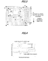
- FIG. 3 is a plan view showing an operating (travel-scheduled) area where the vehicle of FIG. 1 is to be traveled
- FIG. 4 is a waveform diagram showing triaxial outputs of an orientation sensor (geomagnetic sensor) shown in FIG. 1
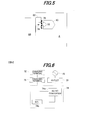
- FIG. 5 is an explanatory view showing charging operation at a charge station shown in FIG. 1
- FIG. 6 is a block diagram showing the configuration of the charge station shown in FIG. 5
- FIG. 5 is an explanatory view of the charge station shown in FIG. 5 .
- FIG. 7 is a block diagram showing the configuration of manipulation equipment used by an operator for the vehicle shown in FIG. 1
- FIG. 8 is a block diagram functionally showing the operation of the apparatus (ECU) shown in FIG. 2
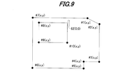
- FIG. 9 is an explanatory view of map information shown in FIG. 8 .
- symbol 10 indicates an autonomous operating vehicle. As shown in FIGs . 1 and 2 , the vehicle 10 is installed with electric motors (prime movers) 12R, 12L for traveling.
- electric motors primary movers
- the motors 12R, 12L are connected to right and left driven wheels 14R, 14L (only the left side shown) attached on the rear side of a chassis 10a of the vehicle 10 and rotates the driven wheels 14R, 14L in the normal (forward traveling) direction or reverse (backward traveling) direction independently of each other.
- Right and left free wheels 16R, 16L are attached on the front side of the chassis 10a of the vehicle 10 through a stay 10b.
- Blades (rotary blades; operating machine) 20 for mowing lawn are attached in the center or thereabout of the chassis 10a.
- the blades 20 are connected to an electric motor 22 for operation to be rotated thereby, and also connected to a blade height adjustment mechanism 24 that can be manually operated by an operator (user).
- the blade height adjustment mechanism 24 is equipped with screws (not shown) to be manually turned by the operator for adjusting the height of the blades 20 from a contact ground GR.
- the chassis 10a is attached with a body frame 10c that covers the motors 12, 22, blades 20 and the like.
- a charging unit (including an AC/DC converter) 26 and a battery 30 are accommodated at the rear of the vehicle 10 and two charging terminals 32 (later shown in FIG. 5 ) are attached to the frame 10c to protrude backward.
- the terminals 32 are connected to the charging unit 26 and the charging unit 26 is connected to the battery 30 through wiring (not shown).
- the battery 30 is connected to the motors 12, 22 through wiring (not shown).
- the vehicle 10 comprises a four-wheel, unmanned, electric lawn-mower vehicle that is, for instance, about 500 millimeters long, 300 millimeters wide and 300 millimeters high and configured to travel within an operating (travel-scheduled) area A shown in FIG. 3 .
- the front and rear ends of the vehicle 10 are attached with ultrasonic sensors 34F, 34R for detecting an obstacle and the frame 10c is attached with a contact sensor 36.
- the contact sensor 36 outputs an ON signal.
- An electronic control unit (ECU) 40 is installed in the center or thereabout of the vehicle 10, more specifically, on a printed-circuit board housed in an ECU housing box 40a.
- the ECU 40 includes a microcomputer having a CPU, ROM, RAM, I/Os, etc.
- An orientation sensor 42 is installed on the board in the ECU housing box 40a in the vicinity of the ECU 40 and generates an output or signal indicative of the primary reference direction on the earth, i.e., the north.
- the orientation sensor 42 comprises a triaxial geomagnetic sensor having outputs mx, my and mz in directions of three axes x, y and z.
- x indicates a traveling direction of the vehicle 10
- y a sideways direction perpendicular to the direction of x
- z a gravitational direction (direction penetrating the plane of paper) perpendicular to the directions of x and y .
- the board in the ECU housing box 40a is also installed near the orientation sensor 42 with a Yaw sensor (angular velocity sensor) 44 that (detects and) produces an output or signal indicative of angular velocity (yaw rate) generated about the z-axis in the center of gravity of the vehicle 10 and with a G sensor (acceleration sensor) 46 that (detects and) produces an output or signal indicative of the longitudinal (traveling) direction acceleration G acting on the vehicle 10.
- Yaw sensor angular velocity sensor
- G sensor acceleration sensor
- a wheel speed sensor 50 is installed near the driven wheel 14 to (detect and) produce an output or signal representing wheel speed thereof.
- a manipulation switch (emergency stop switch) 52 is disposed in the vehicle 10 to be manipulatable by the operator, so that the vehicle 10 is stopped traveling when the switch 52 is turned ON by the operator.
- the outputs of the foregoing ultrasonic sensors 34, contact sensor 36, orientation sensor 42, Yaw sensor 44, G sensor 46, wheel speed sensor 50 and manipulation switch 52 are sent to the ECU 40.
- the upper surface of the frame 10c of the vehicle 10 is widely cut away and a display 54 is installed therein.
- the display 54 is connected to the ECU 40 to show an operation mode, etc., in response to a command sent from the ECU 40.
- a receiving antenna 40b is attached to the ECU housing box 40a and a radio 40c connected to the antenna 40b is installed on the board in the ECU housing box 40a.
- the ECU 40 is connectable with an antitheft authentication device or the like.
- the travel-scheduled area A has a substantially rectangular shape and a house 60, charge station (ST) 62, operating area 64, etc., are arranged therein. Magnetic nails (magnets) 66 are embedded on a border of the travel-scheduled area A and around the house 60.
- the magnetic nails 66 are composed of permanent magnets, such as ferrite for example. Ten magnetic nails 66 of #1 to #10 are embedded on the border of the travel-scheduled area A and the border of the house 60, as illustrated. Since the orientation sensor 42 comprises the geomagnetic sensor, it is responsive to the magnetic nails 66.
- the charge ST 62 is provided in the travel-scheduled area A so that, as shown in FIG. 5 , the vehicle 10 can be stopped and connected to the charge ST 62 through the charging terminals 32 to be charged thereby.
- the charge ST 62 is equipped with a charging device 74 connected to the commercial power source 70 through an electric outlet 72.
- the charging device 74 has an AC/AC converter 74a and an electronic control unit (ECU) 74b controlling the operation of the AC/AC converter 74a, and is connectable to the charging terminals 32 through charging terminals 76.
- ECU electronice control unit
- the voltage of the alternating current coming from the commercial power source 70 through the outlet 72 is appropriately stepped down by the AC/AC converter 74a and, when the vehicle 10 is connected to the charge ST 62 through the charging terminals 32 and 76, the alternating current is supplied to the vehicle 10 and stored in the battery 30 through the charging unit 26.
- Manipulation equipment to be used by the operator for manipulating the vehicle 10 includes a personal computer 80, a radio 82 connected thereto and a remote controller 84, as shown in FIG. 7 .
- the radio 82 and remote controller 84 have transmitting antennas 82a, 84a, respectively, so that they can send operation commands to the ECU 40 through the receiving antenna 40b and radio 40c in the vehicle 10.
- the ECU 40 has a map information storing section 40d that defines or specifies the travel-scheduled area A and stores map information including embedded positions of the magnetic nails 66, etc., indicated with x-y coordinate positions; a primary reference direction and position detecting section 40e that detects a primary reference direction based on the output of the orientation sensor 42, detects a position of the vehicle 10 relative to a specific one of the magnetic nails 66 based on the output of the orientation sensor 42 and detects a position of the vehicle 10 in the travel-scheduled area A based on the detected position and the map information; a direction and distance calculating section 40f that calculates a traveling direction in which the vehicle 10 travels based on the output of the Yaw sensor 44 (and an output of the G sensor 46) and calculates a traveled distance of the vehicle 10 based on the output of the wheel speed sensor 50; a travel and operation (lawnmowing operation) controlling section 40g that controls the operation performed using the blades 20 (operating machine) in the travel
- the direction and distance calculating section 40f calculates the traveling direction based on the angular velocity detected by the Yaw sensor 44 and corrects the calculated traveling direction with the output of the G sensor 46 as necessary.
- the travel and operation controlling section 40g controls the operation of the motors 12 and motor 22 through a motor driver 12a and motor driver 22a, thereby controlling the travel of the vehicle 10.
- the travel and operation controlling section 40g stops the vehicle's traveling.
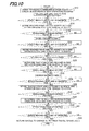
- FIG. 10 is a flowchart showing the foregoing operation of the ECU 40.
- the program begins at S10, in which the travel (lawnmowing operation) of the vehicle 10 is started from the charge ST 62 in accordance with the preset operation program.
- the coordinate position of the charge ST 62 is defined as the origin (0, 0), i.e., the reference position.
- the preset operation program is set so that the vehicle 10 is traveled straight in the direction of the detected primary reference direction, i.e., in the north-south direction, along a designated travel route set in the operating area 64 of the travel-scheduled area A.
- the height of the blades 20 is manually adjusted through the blade height adjustment mechanism 24 by the operator depending on the degree of growth of the lawn in the operating area.
- FIG. 11 is a subroutine flowchart showing the operation.
- a coordinate position (orientation) of a second one of the magnetic nails 66 i.e., the magnetic nail #2 located at the end of the designated travel route is searched from the map information.
- the program proceeds to S102, in which it is determined whether the z-axis output mz of the orientation sensor 42 exceeds a threshold value mzlmt.
- a threshold value mzlmt mzlmt
- the ECU 40 detects the primary reference direction based on the output of the orientation sensor 42, detects a position of the vehicle 10 relative to each of the magnetic nails 66 based on the output of the orientation sensor 42, and detects a position (absolute position) of the vehicle 10 in the travel-scheduled area A based on the detected position and map information.
- absolute position means a position of the vehicle 10 indicated solely with the coordinate position in the travel-scheduled area A.
- the x-axis and y-axis outputs mx, my of the orientation sensor 42 are greatly changed depending on the direction (turning) of the vehicle 10.
- the z-axis output mz is somewhat influenced by a slope in the travel-scheduled area A, the z-axis output mz is apparently not changed depending on the direction (turning) of the vehicle 10. Since magnets having relatively strong magnetic forces are employed as the magnetic nails 66, the embedded positions of the magnetic nails 66 can be detected.
- the inventors found out that it is possible to detect the approach direction of the vehicle 10 to the magnetic nail 66 by, upon appearance of the L-pk of the output mz, searching the peaks, increases and decreases of the x-axis and y-axis outputs.
- the knowledge of found results is shown in FIG. 12 .
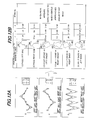
- FIG. 12A is an explanatory view showing the x-axis, y-axis and z-axis outputs with respect to north, south, east and west relative to approach directions (positions) of the vehicle 10 to the magnetic nail 66
- FIG. 12B is an explanatory view showing the approach directions (positions) of the vehicle 10 to the magnetic nail 66.
- L-pk indicates a peak of the sensor output in the minus direction
- U-pk a peak of the sensor output in the plus direction
- Up an increase in the sensor output and Down a decrease in the sensor output.
- the time when the L-pk or U-pk (peak) appears corresponds to the time when the vehicle 10 approaches the magnetic nail 66 the most.
- the threshold value mzlmt is set to a value which enables to determine that the L-pk of the mz output of the orientation sensor 42 appears.
- FIG. 13 is a subroutine flowchart showing the operation.
- the program proceeds to S108, in which the vehicle 10 is moved (or traveled) to above the detected magnetic nail #n (#2). Specifically, the vehicle 10 is moved to above the appropriate magnetic nail 66 so that the position of the vehicle 10 in the travel-scheduled area A is calibrated. In the case where the vehicle 10 is already located above the detected magnetic nail #n, the processing of S108 is omitted.
- the program proceeds to S 14, in which the vehicle 10 is slightly moved to the right side of the magnetic nail #2.
- the program proceeds to S16, in which the point the vehicle 10 is located, including around the point, is defined as an N-side operation edge and the vehicle 10 is turned to the south and traveled straight.
- the control of the motor 22 of the vehicle 10 is explained. Since the right and left driven wheels 14R, 14L are configured so that they can be driven to rotate in the normal and reverse directions through the right and left motors 22R, 22L independently or separately from each other. Consequently, when the motors 22R, 22L are rotated in the normal direction at the same speed, the vehicle 10 is traveled straight, whilst when they are rotated in the normal direction at the different speed, the vehicle 10 is turned to a side of lower rotational speed.
- the program proceeds to S22, in which it is confirmed that the vehicle 10 has reached (or passed) the right side of the magnetic nail #3 and to S24, in which the reached point including around the point is defined as an S-side operation edge and the vehicle 10 is turned to the north and traveled straight toward the N-side operation edge.
- the control apparatus for an autonomous operating vehicle is configured to detect the primary reference direction and the position of the vehicle relative to magnetic nails 66 based on the output of the geomagnetic sensor having x-axis, y-axis and z-axis outputs, mounted on the vehicle 10 and responsive to the magnetic nails 66 embedded in the travel-scheduled area A and the map information, to calculate the traveling direction based on the output of the Yaw sensor 44 and the traveled distance based on the output of the wheel speed sensor 50, and to control the operation performed through the blades 20 in the travel-scheduled area A in accordance with the preset operation program based on the detected primary reference direction, the detected position of the vehicle in the travel-scheduled area A, the calculated traveling direction and the calculated traveled distance.
- FIG. 14 is a flowchart showing the operation of a control apparatus for an autonomous operating vehicle 10 according to a second embodiment of the invention.
- the apparatus according to the second embodiment is configured so that, in the travel control of the vehicle 10, the ECU 40 corrects the traveling direction calculated based on the output of the Yaw sensor 44 with the primary reference direction detected through the processing of S104 in the FIG. 11 flowchart.
- the travel-scheduled area A is not necessarily flat, i.e., could have uneven parts, slopes or slippery parts, and sampling time of the Yaw sensor outputs is limited, they may cause an error in the calculated traveling direction.
- the second embodiment is given to deal with it.
- the program begins in S300, in which a turning command is sent to the motor 12 through the driver 12a and the program proceeds to S302, in which the vehicle 10 is turned by a desired angle (1) (e.g., 30 degrees).
- a desired angle (1) e.g., 30 degrees
- the second embodiment is configured to correct the traveling direction calculated based on the output of the Yaw sensor 44 with the primary reference direction detected through the processing of S104 in the FIG. 11 flowchart.
- the error can be calibrated. Therefore, it becomes possible to control the travel of the vehicle 10 more appropriately, thereby further enhancing the operation performance.
- the remaining configuration as well as the effects is the same as in the first embodiment.
- FIG. 15 is a plan view showing a travel-scheduled area in connection with a control apparatus for an autonomous operating vehicle according to a third embodiment of the invention
- FIG. 16 is a waveform diagram similar to FIG. 4 , but showing magnetic field distortion in outputs of the orientation sensor, which is caused by a device in the travel-scheduled area
- FIG. 17 is a flowchart showing the operation of the ECU 40 of the vehicle 10 according to the third embodiment.
- the program begins in S400, in which the travel (operation) of the vehicle 10 is continued and proceeds to S402, in which it is determined whether a change arises in geomagnetic data detected by the orientation sensor 42.
- the third embodiment is configured to detect the magnetic field variation in the travel-scheduled area A and correct a command value outputted for straight travel based on the detected magnetic field variationf.
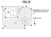
- FIG. 18 is a plan view showing a travel-scheduled area in connection with a control apparatus for an autonomous operating vehicle 10 according to a fourth embodiment of the invention.
- the vehicle's s travel is modified to the extent that the vehicle 10 does not deviate from the operating area 64.
- a command to the motor 12 is changed to make the vehicle 10 travel outward in concentric circles from its straight travel, thereby searching the target magnetic nail 66. After searching it, the position of the vehicle 10 is detected and the operation is continued.
- the operation is stopped and the vehicle 10 is returned to the charge ST 62.
- the absolute position is corrected or calibrated and then the operation is resumed.
- the map information is corrected or calibrated as necessary.
- the fourth embodiment is configured to, when the target magnet nail 66 can not be searched during the vehicle's straight travel, control the operation of the motor 12 to make the vehicle 10 turn or travel in circle.
- the remaining configuration as well as the effects is the same as in the first embodiment.
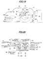
- FIG. 19 is an overall schematic view of a control apparatus for an autonomous operating vehicle 10 according to a fifth embodiment of the invention
- FIG. 20 is a block diagram showing input and output of sensors, etc., mounted on the vehicle
- FIG. 21 is a plan view showing the travel-scheduled area A where the vehicle 10 travels
- FIG. 22 is a block diagram showing the configuration of a charge ST 62.
- the fifth embodiment is configured to lay an area wire (electric wire) 100 along the border of the travel-scheduled area A and install operating area sensors (magnetic sensors) 102F, 102R at the front and rear of the vehicle 10 to detect magnetic field generated along the area wire 100 to recognize the border of the travel-scheduled area A using a known technique disclosed, for example, by '738.
- operating area sensors magnetic sensors
- the charging device 74 of the charge ST 62 includes an area signal generator 74c.
- the area signal generator 74c supplies alternating current to the area wire 100 (i.e., generates an area signal).
- the fifth embodiment is configured to have the area wire 100 and operating area sensors 102, etc., it becomes possible to more reliably detect the border of the travel-scheduled area A.
- the remaining configuration as well as the effects is the same as in the first embodiment.
- an apparatus configured to have an apparatus (ECU 40) and a method for controlling an autonomous operating vehicle (10) having a prime mover (electric motor 12), a driven wheel (14) connected to the prime mover and an operating machine (blades 20), the vehicle autonomously traveling in a travel-scheduled area (A) to perform operation using the operating machine by driving the prime mover, comprising: a geomagnetic sensor (orientation sensor 42) having x-axis, y-axis and z-axis outputs, mounted on the vehicle and responsive to a magnet (magnetic nails 66) embedded in the travel-scheduled area; an angular velocity sensor (Yaw sensor 44) adapted to detect angular velocity generated about z-axis in center of gravity of the vehicle; a wheel speed sensor (50) adapted to produce an output indicative of a wheel speed of the driven wheel of the vehicle; a map information storage (map information storing section 40d) adapted to define the travel-scheduled area and store
- the primary reference direction and position detector (40e) compares the z-axis output of the geomagnetic sensor with a threshold value and detects one of the primary reference direction and the position of the vehicle relative to the magnet in accordance with a result of the comparing.
- the primary reference direction and position detector (40e) detects the position of the vehicle relative to the magnet based on the x-axis, y-axis and z-axis outputs of the geomagnetic sensor when the z-axis output of the geomagnetic sensor exceeds a threshold value (mzlmt).
- the direction and distance calculator (40f) corrects the calculated traveling direction based on the primary reference direction detected by the primary reference direction and position detector.
- the travel and operation controller (40g) controls the prime mover to make straight travel in a direction of the primary reference direction detected by the primary reference direction and position detector when the operation is performed.
- the primary reference direction and position detector (40e) includes a magnetic field variation detector (S406) adapted to detect variation in magnetic field in the travel-scheduled area and corrects a command value outputted for the straight travel based on the magnetic field variation.
- the travel and operation controller (40g) controls the prime mover to turn or travel the vehicle in circle when the magnet has not been searched during the straight travel.
- the prime mover comprises an electric motor, a charge station (62) is provided in the travel-scheduled area to charge the motor, and the charge station is defined as a reference position (origin) in the map information.
- the motor 12 is applied as the prime mover, it may be an internal combustion engine or another prime mover instead.
- the blades 20 for mowing lawn are exemplified as the operating machine, but it should not be limited thereto. Further, other kinds of magnets can be utilized in place of the magnetic nails.
- an apparatus for controlling an autonomous operating vehicle having a prime mover and operating machine it is configured to have a geomagnetic sensor responsive to magnets embedded in the area, detect angular velocity generated about z-axis in center of gravity of the vehicle, detect a wheel speed of the driven wheel, store map information including magnet embedded positions, detect a primary reference direction, detect a vehicle position relative to the magnet and detect a vehicle position in the area (S12, S20, S32), calculate a traveling direction and traveled distance of the vehicle, and control the operation performed through the operating machine in the area in accordance with a preset operation program based on the detected primary reference direction, the detected position of the vehicle in the area, the calculated traveling direction and the calculated traveled distance (S10 to S46).
Landscapes
- Engineering & Computer Science (AREA)
- Radar, Positioning & Navigation (AREA)
- Physics & Mathematics (AREA)
- Remote Sensing (AREA)
- Aviation & Aerospace Engineering (AREA)
- General Physics & Mathematics (AREA)
- Automation & Control Theory (AREA)
- Electromagnetism (AREA)
- Control Of Position, Course, Altitude, Or Attitude Of Moving Bodies (AREA)
Applications Claiming Priority (1)
| Application Number | Priority Date | Filing Date | Title |
|---|---|---|---|
| JP2010222640 | 2010-09-30 |
Publications (2)
| Publication Number | Publication Date |
|---|---|
| EP2437130A1 true EP2437130A1 (de) | 2012-04-04 |
| EP2437130B1 EP2437130B1 (de) | 2013-08-07 |
Family
ID=44677745
Family Applications (1)
| Application Number | Title | Priority Date | Filing Date |
|---|---|---|---|
| EP11182939.6A Active EP2437130B1 (de) | 2010-09-30 | 2011-09-27 | Steuerungsvorrichtung für Automobilfahrzeug |
Country Status (3)
| Country | Link |
|---|---|
| US (1) | US8712623B2 (de) |
| EP (1) | EP2437130B1 (de) |
| JP (1) | JP5712097B2 (de) |
Cited By (2)
| Publication number | Priority date | Publication date | Assignee | Title |
|---|---|---|---|---|
| EP3686706A1 (de) * | 2014-11-07 | 2020-07-29 | F. Robotics Acquisitions Ltd. | Ortungsmoduswechsel für einen haushaltsroboter |
| EP3835907A4 (de) * | 2018-08-08 | 2022-04-20 | Positec Power Tools (Suzhou) Co., Ltd | Selbstmobile vorrichtung, automatisches betriebssystem und steuerungsverfahren dafür |
Families Citing this family (34)
| Publication number | Priority date | Publication date | Assignee | Title |
|---|---|---|---|---|
| CA2806852C (en) * | 2010-08-03 | 2018-09-04 | Fori Automation, Inc. | Sensor system and method for use with an automated guided vehicle (agv) |
| US9218316B2 (en) | 2011-01-05 | 2015-12-22 | Sphero, Inc. | Remotely controlling a self-propelled device in a virtualized environment |
| US9429940B2 (en) | 2011-01-05 | 2016-08-30 | Sphero, Inc. | Self propelled device with magnetic coupling |
| US9114838B2 (en) | 2011-01-05 | 2015-08-25 | Sphero, Inc. | Self-propelled device for interpreting input from a controller device |
| US9090214B2 (en) | 2011-01-05 | 2015-07-28 | Orbotix, Inc. | Magnetically coupled accessory for a self-propelled device |
| US10281915B2 (en) | 2011-01-05 | 2019-05-07 | Sphero, Inc. | Multi-purposed self-propelled device |
| US20120244969A1 (en) | 2011-03-25 | 2012-09-27 | May Patents Ltd. | System and Method for a Motion Sensing Device |
| HK1207455A1 (en) | 2012-05-14 | 2016-01-29 | 斯飞乐有限公司 | Operating a computing device by detecting rounded objects in an image |
| US9827487B2 (en) | 2012-05-14 | 2017-11-28 | Sphero, Inc. | Interactive augmented reality using a self-propelled device |
| US10056791B2 (en) | 2012-07-13 | 2018-08-21 | Sphero, Inc. | Self-optimizing power transfer |
| CN103823464A (zh) * | 2012-11-16 | 2014-05-28 | 苏州宝时得电动工具有限公司 | 自驱动移动装置 |
| EP2939508B1 (de) | 2012-12-28 | 2021-05-19 | Positec Power Tools (Suzhou) Co., Ltd | Automatisiertes mähsystem |
| JP6085883B2 (ja) * | 2013-08-10 | 2017-03-01 | みのる産業株式会社 | 自律走行車 |
| US9829882B2 (en) | 2013-12-20 | 2017-11-28 | Sphero, Inc. | Self-propelled device with center of mass drive system |
| CN103679851B (zh) * | 2013-12-27 | 2016-08-24 | 李德毅 | 一种多传感器数据处理免同步方法及系统 |
| JP2017535279A (ja) | 2014-09-23 | 2017-11-30 | 宝時得科技(中国)有限公司Positec Technology (China) Co.,Ltd. | 自動移動ロボット |
| JP6014192B1 (ja) * | 2015-03-27 | 2016-10-25 | 本田技研工業株式会社 | 無人作業車の制御装置 |
| CN106441296A (zh) * | 2015-08-04 | 2017-02-22 | 中兴通讯股份有限公司 | 运动轨迹记录方法和用户设备 |
| US20170102704A1 (en) * | 2015-10-13 | 2017-04-13 | Delphi Technologies, Inc. | Automated Vehicle Object Detection Device With Level Detection |
| JP6212591B2 (ja) * | 2016-03-31 | 2017-10-11 | 本田技研工業株式会社 | 自律走行作業車の制御装置 |
| JP6212590B2 (ja) * | 2016-03-31 | 2017-10-11 | 本田技研工業株式会社 | 自律走行作業車の制御装置 |
| JP6285979B2 (ja) * | 2016-03-31 | 2018-02-28 | 本田技研工業株式会社 | 充電ステーションおよび自律走行作業車の充電ステーション誘導装置 |
| US11172608B2 (en) | 2016-06-30 | 2021-11-16 | Tti (Macao Commercial Offshore) Limited | Autonomous lawn mower and a system for navigating thereof |
| WO2018000922A1 (en) | 2016-06-30 | 2018-01-04 | Tti (Macao Commercial Offshore) Limited | An autonomous lawn mower and a system for navigating thereof |
| US10696307B2 (en) | 2018-07-10 | 2020-06-30 | Ford Global Technologies, Llc | Anomaly detector for vehicle control signals |
| WO2020156684A1 (en) | 2019-02-01 | 2020-08-06 | Positec Power Tools (Suzhou) Co., Ltd. | Self moving device and magnetic boundary system |
| US20210382498A1 (en) * | 2020-06-09 | 2021-12-09 | Thomas Philip Ramstack | Mobility assist apparatus and method |
| US12296694B2 (en) | 2021-03-10 | 2025-05-13 | Techtronic Cordless Gp | Lawnmowers |
| US12443180B2 (en) | 2021-11-10 | 2025-10-14 | Techtronic Cordless Gp | Robotic lawn mowers |
| AU2023200381A1 (en) | 2022-01-31 | 2023-08-17 | Techtronic Cordless Gp | Robotic garden tool |
| EP4270138A1 (de) | 2022-04-28 | 2023-11-01 | Techtronic Cordless GP | Erzeugung einer virtuellen grenze für ein robotisches gartenwerkzeug |
| US12472611B2 (en) | 2022-05-31 | 2025-11-18 | Techtronic Cordless Gp | Peg driver |
| EP4310621B1 (de) | 2022-07-19 | 2025-02-12 | Techtronic Cordless GP | Anzeige zur steuerung eines robotischen werkzeugs |
| AU2023206123A1 (en) | 2022-07-29 | 2024-02-15 | Techtronic Cordless Gp | Generation of a cryptography key for a robotic garden tool |
Citations (4)
| Publication number | Priority date | Publication date | Assignee | Title |
|---|---|---|---|---|
| JPS60239812A (ja) | 1984-05-14 | 1985-11-28 | Mitsubishi Electric Corp | 移動体の移動領域限定装置 |
| JPH08286738A (ja) | 1995-04-17 | 1996-11-01 | Kubota Corp | 移動車の誘導制御装置 |
| GB2307062A (en) * | 1995-11-07 | 1997-05-14 | Fuji Heavy Ind Ltd | Autonomous vehicle control system |
| US20070150109A1 (en) * | 1998-05-11 | 2007-06-28 | Ehud Peless | Area coverage with an autonomous robot |
Family Cites Families (9)
| Publication number | Priority date | Publication date | Assignee | Title |
|---|---|---|---|---|
| JPH01130207A (ja) * | 1987-11-16 | 1989-05-23 | Fanuc Ltd | 走行ロボットの走行制御方式 |
| US5347456A (en) * | 1991-05-22 | 1994-09-13 | The Regents Of The University Of California | Intelligent roadway reference system for vehicle lateral guidance and control |
| IL113913A (en) * | 1995-05-30 | 2000-02-29 | Friendly Machines Ltd | Navigation method and system |
| JPH0937610A (ja) * | 1995-08-01 | 1997-02-10 | Hitachi Ltd | 無人芝刈り機の運転方式 |
| JP3380098B2 (ja) * | 1995-10-12 | 2003-02-24 | 日本輸送機株式会社 | 無人作業車の自律演算補正方法および自律演算補正装置 |
| JP2002230683A (ja) * | 2001-02-06 | 2002-08-16 | Tdk Corp | 車載用磁気センサ及びそれを備えた車両位置検出装置 |
| US6907336B2 (en) * | 2003-03-31 | 2005-06-14 | Deere & Company | Method and system for efficiently traversing an area with a work vehicle |
| JP2005103678A (ja) * | 2003-09-29 | 2005-04-21 | Toshiba Corp | ロボット装置 |
| JP5130419B2 (ja) * | 2008-05-30 | 2013-01-30 | 国立大学法人宇都宮大学 | 自己位置認識方法及び自己位置認識装置 |
-
2011
- 2011-09-20 JP JP2011204501A patent/JP5712097B2/ja not_active Expired - Fee Related
- 2011-09-22 US US13/240,966 patent/US8712623B2/en active Active
- 2011-09-27 EP EP11182939.6A patent/EP2437130B1/de active Active
Patent Citations (5)
| Publication number | Priority date | Publication date | Assignee | Title |
|---|---|---|---|---|
| JPS60239812A (ja) | 1984-05-14 | 1985-11-28 | Mitsubishi Electric Corp | 移動体の移動領域限定装置 |
| JPH08286738A (ja) | 1995-04-17 | 1996-11-01 | Kubota Corp | 移動車の誘導制御装置 |
| GB2307062A (en) * | 1995-11-07 | 1997-05-14 | Fuji Heavy Ind Ltd | Autonomous vehicle control system |
| JP3467136B2 (ja) | 1995-11-07 | 2003-11-17 | 富士重工業株式会社 | 自律走行車の走行制御装置 |
| US20070150109A1 (en) * | 1998-05-11 | 2007-06-28 | Ehud Peless | Area coverage with an autonomous robot |
Cited By (2)
| Publication number | Priority date | Publication date | Assignee | Title |
|---|---|---|---|---|
| EP3686706A1 (de) * | 2014-11-07 | 2020-07-29 | F. Robotics Acquisitions Ltd. | Ortungsmoduswechsel für einen haushaltsroboter |
| EP3835907A4 (de) * | 2018-08-08 | 2022-04-20 | Positec Power Tools (Suzhou) Co., Ltd | Selbstmobile vorrichtung, automatisches betriebssystem und steuerungsverfahren dafür |
Also Published As
| Publication number | Publication date |
|---|---|
| JP2012094123A (ja) | 2012-05-17 |
| JP5712097B2 (ja) | 2015-05-07 |
| EP2437130B1 (de) | 2013-08-07 |
| US20120083962A1 (en) | 2012-04-05 |
| US8712623B2 (en) | 2014-04-29 |
Similar Documents
| Publication | Publication Date | Title |
|---|---|---|
| EP2437130B1 (de) | Steuerungsvorrichtung für Automobilfahrzeug | |
| EP2437131B1 (de) | Steuerungsvorrichtung für ein autonom arbeitendes Fahrzeug | |
| EP2437132B1 (de) | Steuerungsvorrichtung für Automobilfahrzeug | |
| US10454287B2 (en) | Charging station for utility vehicle | |
| US9876370B2 (en) | Charging station and charging station guide for autonomously navigating utility vehicle | |
| US9483053B2 (en) | Arrangement of area wire for unmanned autonomous operating vehicle and control apparatus of the same | |
| US9888625B2 (en) | Control apparatus for autonomously navigating utility vehicle | |
| US10268206B2 (en) | Control apparatus for utility vehicle | |
| US9063547B2 (en) | Control apparatus of unmanned autonomous operating vehicle | |
| EP2626759B1 (de) | Führungsvorrichtung eines unbemannten autonom betriebenen Fahrzeugs | |
| US12510891B2 (en) | Travel route control of autonomous work vehicle to reduce travel distance | |
| US12130633B2 (en) | Travel route control of autonomous work vehicle |
Legal Events
| Date | Code | Title | Description |
|---|---|---|---|
| PUAI | Public reference made under article 153(3) epc to a published international application that has entered the european phase |
Free format text: ORIGINAL CODE: 0009012 |
|
| 17P | Request for examination filed |
Effective date: 20110927 |
|
| AK | Designated contracting states |
Kind code of ref document: A1 Designated state(s): AL AT BE BG CH CY CZ DE DK EE ES FI FR GB GR HR HU IE IS IT LI LT LU LV MC MK MT NL NO PL PT RO RS SE SI SK SM TR |
|
| AX | Request for extension of the european patent |
Extension state: BA ME |
|
| RIC1 | Information provided on ipc code assigned before grant |
Ipc: G05D 1/02 20060101AFI20130116BHEP |
|
| GRAP | Despatch of communication of intention to grant a patent |
Free format text: ORIGINAL CODE: EPIDOSNIGR1 |
|
| GRAS | Grant fee paid |
Free format text: ORIGINAL CODE: EPIDOSNIGR3 |
|
| GRAA | (expected) grant |
Free format text: ORIGINAL CODE: 0009210 |
|
| AK | Designated contracting states |
Kind code of ref document: B1 Designated state(s): AL AT BE BG CH CY CZ DE DK EE ES FI FR GB GR HR HU IE IS IT LI LT LU LV MC MK MT NL NO PL PT RO RS SE SI SK SM TR |
|
| REG | Reference to a national code |
Ref country code: GB Ref legal event code: FG4D |
|
| REG | Reference to a national code |
Ref country code: CH Ref legal event code: EP Ref country code: AT Ref legal event code: REF Ref document number: 626018 Country of ref document: AT Kind code of ref document: T Effective date: 20130815 |
|
| REG | Reference to a national code |
Ref country code: IE Ref legal event code: FG4D |
|
| REG | Reference to a national code |
Ref country code: DE Ref legal event code: R096 Ref document number: 602011002600 Country of ref document: DE Effective date: 20131002 |
|
| REG | Reference to a national code |
Ref country code: SE Ref legal event code: TRGR |
|
| REG | Reference to a national code |
Ref country code: AT Ref legal event code: MK05 Ref document number: 626018 Country of ref document: AT Kind code of ref document: T Effective date: 20130807 |
|
| REG | Reference to a national code |
Ref country code: NL Ref legal event code: VDEP Effective date: 20130807 |
|
| REG | Reference to a national code |
Ref country code: LT Ref legal event code: MG4D |
|
| PG25 | Lapsed in a contracting state [announced via postgrant information from national office to epo] |
Ref country code: PT Free format text: LAPSE BECAUSE OF FAILURE TO SUBMIT A TRANSLATION OF THE DESCRIPTION OR TO PAY THE FEE WITHIN THE PRESCRIBED TIME-LIMIT Effective date: 20131209 Ref country code: LT Free format text: LAPSE BECAUSE OF FAILURE TO SUBMIT A TRANSLATION OF THE DESCRIPTION OR TO PAY THE FEE WITHIN THE PRESCRIBED TIME-LIMIT Effective date: 20130807 Ref country code: AT Free format text: LAPSE BECAUSE OF FAILURE TO SUBMIT A TRANSLATION OF THE DESCRIPTION OR TO PAY THE FEE WITHIN THE PRESCRIBED TIME-LIMIT Effective date: 20130807 Ref country code: CY Free format text: LAPSE BECAUSE OF FAILURE TO SUBMIT A TRANSLATION OF THE DESCRIPTION OR TO PAY THE FEE WITHIN THE PRESCRIBED TIME-LIMIT Effective date: 20130821 Ref country code: IS Free format text: LAPSE BECAUSE OF FAILURE TO SUBMIT A TRANSLATION OF THE DESCRIPTION OR TO PAY THE FEE WITHIN THE PRESCRIBED TIME-LIMIT Effective date: 20131207 Ref country code: NO Free format text: LAPSE BECAUSE OF FAILURE TO SUBMIT A TRANSLATION OF THE DESCRIPTION OR TO PAY THE FEE WITHIN THE PRESCRIBED TIME-LIMIT Effective date: 20131107 Ref country code: HR Free format text: LAPSE BECAUSE OF FAILURE TO SUBMIT A TRANSLATION OF THE DESCRIPTION OR TO PAY THE FEE WITHIN THE PRESCRIBED TIME-LIMIT Effective date: 20130807 |
|
| PG25 | Lapsed in a contracting state [announced via postgrant information from national office to epo] |
Ref country code: NL Free format text: LAPSE BECAUSE OF FAILURE TO SUBMIT A TRANSLATION OF THE DESCRIPTION OR TO PAY THE FEE WITHIN THE PRESCRIBED TIME-LIMIT Effective date: 20130807 Ref country code: FI Free format text: LAPSE BECAUSE OF FAILURE TO SUBMIT A TRANSLATION OF THE DESCRIPTION OR TO PAY THE FEE WITHIN THE PRESCRIBED TIME-LIMIT Effective date: 20130807 Ref country code: GR Free format text: LAPSE BECAUSE OF FAILURE TO SUBMIT A TRANSLATION OF THE DESCRIPTION OR TO PAY THE FEE WITHIN THE PRESCRIBED TIME-LIMIT Effective date: 20131108 Ref country code: SI Free format text: LAPSE BECAUSE OF FAILURE TO SUBMIT A TRANSLATION OF THE DESCRIPTION OR TO PAY THE FEE WITHIN THE PRESCRIBED TIME-LIMIT Effective date: 20130807 Ref country code: LV Free format text: LAPSE BECAUSE OF FAILURE TO SUBMIT A TRANSLATION OF THE DESCRIPTION OR TO PAY THE FEE WITHIN THE PRESCRIBED TIME-LIMIT Effective date: 20130807 Ref country code: BE Free format text: LAPSE BECAUSE OF FAILURE TO SUBMIT A TRANSLATION OF THE DESCRIPTION OR TO PAY THE FEE WITHIN THE PRESCRIBED TIME-LIMIT Effective date: 20130807 Ref country code: PL Free format text: LAPSE BECAUSE OF FAILURE TO SUBMIT A TRANSLATION OF THE DESCRIPTION OR TO PAY THE FEE WITHIN THE PRESCRIBED TIME-LIMIT Effective date: 20130807 |
|
| PG25 | Lapsed in a contracting state [announced via postgrant information from national office to epo] |
Ref country code: CY Free format text: LAPSE BECAUSE OF FAILURE TO SUBMIT A TRANSLATION OF THE DESCRIPTION OR TO PAY THE FEE WITHIN THE PRESCRIBED TIME-LIMIT Effective date: 20130807 |
|
| PG25 | Lapsed in a contracting state [announced via postgrant information from national office to epo] |
Ref country code: CZ Free format text: LAPSE BECAUSE OF FAILURE TO SUBMIT A TRANSLATION OF THE DESCRIPTION OR TO PAY THE FEE WITHIN THE PRESCRIBED TIME-LIMIT Effective date: 20130807 Ref country code: RO Free format text: LAPSE BECAUSE OF FAILURE TO SUBMIT A TRANSLATION OF THE DESCRIPTION OR TO PAY THE FEE WITHIN THE PRESCRIBED TIME-LIMIT Effective date: 20130807 Ref country code: SK Free format text: LAPSE BECAUSE OF FAILURE TO SUBMIT A TRANSLATION OF THE DESCRIPTION OR TO PAY THE FEE WITHIN THE PRESCRIBED TIME-LIMIT Effective date: 20130807 Ref country code: EE Free format text: LAPSE BECAUSE OF FAILURE TO SUBMIT A TRANSLATION OF THE DESCRIPTION OR TO PAY THE FEE WITHIN THE PRESCRIBED TIME-LIMIT Effective date: 20130807 Ref country code: DK Free format text: LAPSE BECAUSE OF FAILURE TO SUBMIT A TRANSLATION OF THE DESCRIPTION OR TO PAY THE FEE WITHIN THE PRESCRIBED TIME-LIMIT Effective date: 20130807 |
|
| PG25 | Lapsed in a contracting state [announced via postgrant information from national office to epo] |
Ref country code: ES Free format text: LAPSE BECAUSE OF FAILURE TO SUBMIT A TRANSLATION OF THE DESCRIPTION OR TO PAY THE FEE WITHIN THE PRESCRIBED TIME-LIMIT Effective date: 20130807 Ref country code: MC Free format text: LAPSE BECAUSE OF FAILURE TO SUBMIT A TRANSLATION OF THE DESCRIPTION OR TO PAY THE FEE WITHIN THE PRESCRIBED TIME-LIMIT Effective date: 20130807 |
|
| PLBE | No opposition filed within time limit |
Free format text: ORIGINAL CODE: 0009261 |
|
| STAA | Information on the status of an ep patent application or granted ep patent |
Free format text: STATUS: NO OPPOSITION FILED WITHIN TIME LIMIT |
|
| REG | Reference to a national code |
Ref country code: IE Ref legal event code: MM4A |
|
| 26N | No opposition filed |
Effective date: 20140508 |
|
| PG25 | Lapsed in a contracting state [announced via postgrant information from national office to epo] |
Ref country code: IE Free format text: LAPSE BECAUSE OF NON-PAYMENT OF DUE FEES Effective date: 20130927 |
|
| REG | Reference to a national code |
Ref country code: DE Ref legal event code: R097 Ref document number: 602011002600 Country of ref document: DE Effective date: 20140508 |
|
| REG | Reference to a national code |
Ref country code: CH Ref legal event code: PL |
|
| PG25 | Lapsed in a contracting state [announced via postgrant information from national office to epo] |
Ref country code: SM Free format text: LAPSE BECAUSE OF FAILURE TO SUBMIT A TRANSLATION OF THE DESCRIPTION OR TO PAY THE FEE WITHIN THE PRESCRIBED TIME-LIMIT Effective date: 20130807 |
|
| PG25 | Lapsed in a contracting state [announced via postgrant information from national office to epo] |
Ref country code: TR Free format text: LAPSE BECAUSE OF FAILURE TO SUBMIT A TRANSLATION OF THE DESCRIPTION OR TO PAY THE FEE WITHIN THE PRESCRIBED TIME-LIMIT Effective date: 20130807 Ref country code: MT Free format text: LAPSE BECAUSE OF FAILURE TO SUBMIT A TRANSLATION OF THE DESCRIPTION OR TO PAY THE FEE WITHIN THE PRESCRIBED TIME-LIMIT Effective date: 20130807 |
|
| PG25 | Lapsed in a contracting state [announced via postgrant information from national office to epo] |
Ref country code: RS Free format text: LAPSE BECAUSE OF FAILURE TO SUBMIT A TRANSLATION OF THE DESCRIPTION OR TO PAY THE FEE WITHIN THE PRESCRIBED TIME-LIMIT Effective date: 20131107 Ref country code: LI Free format text: LAPSE BECAUSE OF NON-PAYMENT OF DUE FEES Effective date: 20140930 Ref country code: LU Free format text: LAPSE BECAUSE OF NON-PAYMENT OF DUE FEES Effective date: 20130927 Ref country code: BG Free format text: LAPSE BECAUSE OF FAILURE TO SUBMIT A TRANSLATION OF THE DESCRIPTION OR TO PAY THE FEE WITHIN THE PRESCRIBED TIME-LIMIT Effective date: 20130807 Ref country code: MK Free format text: LAPSE BECAUSE OF FAILURE TO SUBMIT A TRANSLATION OF THE DESCRIPTION OR TO PAY THE FEE WITHIN THE PRESCRIBED TIME-LIMIT Effective date: 20130807 Ref country code: HU Free format text: LAPSE BECAUSE OF FAILURE TO SUBMIT A TRANSLATION OF THE DESCRIPTION OR TO PAY THE FEE WITHIN THE PRESCRIBED TIME-LIMIT; INVALID AB INITIO Effective date: 20110927 Ref country code: CH Free format text: LAPSE BECAUSE OF NON-PAYMENT OF DUE FEES Effective date: 20140930 |
|
| REG | Reference to a national code |
Ref country code: FR Ref legal event code: PLFP Year of fee payment: 6 |
|
| REG | Reference to a national code |
Ref country code: FR Ref legal event code: PLFP Year of fee payment: 7 |
|
| REG | Reference to a national code |
Ref country code: FR Ref legal event code: PLFP Year of fee payment: 8 |
|
| PG25 | Lapsed in a contracting state [announced via postgrant information from national office to epo] |
Ref country code: AL Free format text: LAPSE BECAUSE OF FAILURE TO SUBMIT A TRANSLATION OF THE DESCRIPTION OR TO PAY THE FEE WITHIN THE PRESCRIBED TIME-LIMIT Effective date: 20130807 |
|
| PGFP | Annual fee paid to national office [announced via postgrant information from national office to epo] |
Ref country code: IT Payment date: 20190917 Year of fee payment: 9 Ref country code: SE Payment date: 20190910 Year of fee payment: 9 |
|
| REG | Reference to a national code |
Ref country code: DE Ref legal event code: R084 Ref document number: 602011002600 Country of ref document: DE |
|
| REG | Reference to a national code |
Ref country code: GB Ref legal event code: 746 Effective date: 20191219 |
|
| PGFP | Annual fee paid to national office [announced via postgrant information from national office to epo] |
Ref country code: GB Payment date: 20200916 Year of fee payment: 10 |
|
| PG25 | Lapsed in a contracting state [announced via postgrant information from national office to epo] |
Ref country code: SE Free format text: LAPSE BECAUSE OF NON-PAYMENT OF DUE FEES Effective date: 20200928 |
|
| REG | Reference to a national code |
Ref country code: SE Ref legal event code: EUG |
|
| PG25 | Lapsed in a contracting state [announced via postgrant information from national office to epo] |
Ref country code: IT Free format text: LAPSE BECAUSE OF NON-PAYMENT OF DUE FEES Effective date: 20200927 |
|
| GBPC | Gb: european patent ceased through non-payment of renewal fee |
Effective date: 20210927 |
|
| PG25 | Lapsed in a contracting state [announced via postgrant information from national office to epo] |
Ref country code: GB Free format text: LAPSE BECAUSE OF NON-PAYMENT OF DUE FEES Effective date: 20210927 |
|
| PGFP | Annual fee paid to national office [announced via postgrant information from national office to epo] |
Ref country code: FR Payment date: 20220808 Year of fee payment: 12 |
|
| REG | Reference to a national code |
Ref country code: DE Ref legal event code: R079 Ref document number: 602011002600 Country of ref document: DE Free format text: PREVIOUS MAIN CLASS: G05D0001020000 Ipc: G05D0001430000 |
|
| PG25 | Lapsed in a contracting state [announced via postgrant information from national office to epo] |
Ref country code: FR Free format text: LAPSE BECAUSE OF NON-PAYMENT OF DUE FEES Effective date: 20230930 |
|
| PGFP | Annual fee paid to national office [announced via postgrant information from national office to epo] |
Ref country code: DE Payment date: 20250820 Year of fee payment: 15 |