EP2442018A2 - Lampe de véhicule automobile - Google Patents
Lampe de véhicule automobile Download PDFInfo
- Publication number
- EP2442018A2 EP2442018A2 EP11182191A EP11182191A EP2442018A2 EP 2442018 A2 EP2442018 A2 EP 2442018A2 EP 11182191 A EP11182191 A EP 11182191A EP 11182191 A EP11182191 A EP 11182191A EP 2442018 A2 EP2442018 A2 EP 2442018A2
- Authority
- EP
- European Patent Office
- Prior art keywords
- motor vehicle
- pad
- electrically conductive
- carrier
- lamp
- Prior art date
- Legal status (The legal status is an assumption and is not a legal conclusion. Google has not performed a legal analysis and makes no representation as to the accuracy of the status listed.)
- Granted
Links
Images
Classifications
-
- B—PERFORMING OPERATIONS; TRANSPORTING
- B60—VEHICLES IN GENERAL
- B60Q—ARRANGEMENT OF SIGNALLING OR LIGHTING DEVICES, THE MOUNTING OR SUPPORTING THEREOF OR CIRCUITS THEREFOR, FOR VEHICLES IN GENERAL
- B60Q1/00—Arrangement of optical signalling or lighting devices, the mounting or supporting thereof or circuits therefor
- B60Q1/26—Arrangement of optical signalling or lighting devices, the mounting or supporting thereof or circuits therefor the devices being primarily intended to indicate the vehicle, or parts thereof, or to give signals, to other traffic
- B60Q1/2696—Mounting of devices using LEDs
-
- F—MECHANICAL ENGINEERING; LIGHTING; HEATING; WEAPONS; BLASTING
- F21—LIGHTING
- F21S—NON-PORTABLE LIGHTING DEVICES; SYSTEMS THEREOF; VEHICLE LIGHTING DEVICES SPECIALLY ADAPTED FOR VEHICLE EXTERIORS
- F21S41/00—Illuminating devices specially adapted for vehicle exteriors, e.g. headlamps
- F21S41/10—Illuminating devices specially adapted for vehicle exteriors, e.g. headlamps characterised by the light source
- F21S41/19—Attachment of light sources or lamp holders
- F21S41/192—Details of lamp holders, terminals or connectors
-
- F—MECHANICAL ENGINEERING; LIGHTING; HEATING; WEAPONS; BLASTING
- F21—LIGHTING
- F21S—NON-PORTABLE LIGHTING DEVICES; SYSTEMS THEREOF; VEHICLE LIGHTING DEVICES SPECIALLY ADAPTED FOR VEHICLE EXTERIORS
- F21S43/00—Signalling devices specially adapted for vehicle exteriors, e.g. brake lamps, direction indicator lights or reversing lights
- F21S43/10—Signalling devices specially adapted for vehicle exteriors, e.g. brake lamps, direction indicator lights or reversing lights characterised by the light source
- F21S43/19—Attachment of light sources or lamp holders
- F21S43/195—Details of lamp holders, terminals or connectors
-
- F—MECHANICAL ENGINEERING; LIGHTING; HEATING; WEAPONS; BLASTING
- F21—LIGHTING
- F21S—NON-PORTABLE LIGHTING DEVICES; SYSTEMS THEREOF; VEHICLE LIGHTING DEVICES SPECIALLY ADAPTED FOR VEHICLE EXTERIORS
- F21S45/00—Arrangements within vehicle lighting devices specially adapted for vehicle exteriors, for purposes other than emission or distribution of light
- F21S45/10—Protection of lighting devices
-
- H—ELECTRICITY
- H05—ELECTRIC TECHNIQUES NOT OTHERWISE PROVIDED FOR
- H05K—PRINTED CIRCUITS; CASINGS OR CONSTRUCTIONAL DETAILS OF ELECTRIC APPARATUS; MANUFACTURE OF ASSEMBLAGES OF ELECTRICAL COMPONENTS
- H05K1/00—Printed circuits
- H05K1/02—Details
- H05K1/0213—Electrical arrangements not otherwise provided for
- H05K1/0254—High voltage adaptations; Electrical insulation details; Overvoltage or electrostatic discharge protection ; Arrangements for regulating voltages or for using plural voltages
- H05K1/0257—Overvoltage protection
- H05K1/0259—Electrostatic discharge [ESD] protection
-
- H—ELECTRICITY
- H05—ELECTRIC TECHNIQUES NOT OTHERWISE PROVIDED FOR
- H05K—PRINTED CIRCUITS; CASINGS OR CONSTRUCTIONAL DETAILS OF ELECTRIC APPARATUS; MANUFACTURE OF ASSEMBLAGES OF ELECTRICAL COMPONENTS
- H05K1/00—Printed circuits
- H05K1/02—Details
- H05K1/11—Printed elements for providing electric connections to or between printed circuits
- H05K1/117—Pads along the edge of rigid circuit boards, e.g. for pluggable connectors
-
- H—ELECTRICITY
- H05—ELECTRIC TECHNIQUES NOT OTHERWISE PROVIDED FOR
- H05K—PRINTED CIRCUITS; CASINGS OR CONSTRUCTIONAL DETAILS OF ELECTRIC APPARATUS; MANUFACTURE OF ASSEMBLAGES OF ELECTRICAL COMPONENTS
- H05K2201/00—Indexing scheme relating to printed circuits covered by H05K1/00
- H05K2201/03—Conductive materials
- H05K2201/0302—Properties and characteristics in general
- H05K2201/0314—Elastomeric connector or conductor, e.g. rubber with metallic filler
-
- H—ELECTRICITY
- H05—ELECTRIC TECHNIQUES NOT OTHERWISE PROVIDED FOR
- H05K—PRINTED CIRCUITS; CASINGS OR CONSTRUCTIONAL DETAILS OF ELECTRIC APPARATUS; MANUFACTURE OF ASSEMBLAGES OF ELECTRICAL COMPONENTS
- H05K2201/00—Indexing scheme relating to printed circuits covered by H05K1/00
- H05K2201/10—Details of components or other objects attached to or integrated in a printed circuit board
- H05K2201/10007—Types of components
- H05K2201/10106—Light emitting diode [LED]
Definitions
- the invention relates to a motor vehicle lamp according to the preamble of claim 1.
- a motor vehicle light fulfills one or more tasks or functions, such as, for example, a function illuminating the roadway as a headlight, or a signaling function as signal light, such as for indicating the direction of travel or indicating a braking activity, or ensuring visibility the vehicle during the day and / or night, such as in a design as a daytime running light.
- a function illuminating the roadway as a headlight or a signaling function as signal light, such as for indicating the direction of travel or indicating a braking activity, or ensuring visibility the vehicle during the day and / or night, such as in a design as a daytime running light.
- motor vehicle lights are on the vehicle's bow, on the vehicle flanks and / or on the side mirrors and rear lights arranged flashing lights, for example, ambient lighting, marker lights, brake lights, fog lights, reversing lights, and typically high set third brake lights, so-called Central, High-Mounted Braking lights, daytime running lights, headlamps and fog lights used as turning or cornering lights, as well as combinations thereof.
- flashing lights for example, ambient lighting, marker lights, brake lights, fog lights, reversing lights, and typically high set third brake lights, so-called Central, High-Mounted Braking lights, daytime running lights, headlamps and fog lights used as turning or cornering lights, as well as combinations thereof.
- a motor vehicle luminaire essentially comprises a housing, a luminous means arranged therein, optionally a reflector arranged behind the luminous means in the housing and / or an optical element arranged in front of the luminous element, such as a lens, a trough concentrator, eg a parabolic trough (CPC; Parabolic Concentrator) or the like for shaping a defined emission characteristic, as well as a transparent cover protecting the illuminant and optionally the reflector or the optic element against the effects of weathering, in short also referred to as a lens.
- the lens encloses together with the housing a lamp and possibly the reflector receiving the lamp interior.
- an optical disc can be arranged between the illuminant and the lens, which can have a specific structure and / or masking, for example, in order to conceal the luminous means in the case of a clear lens effecting a depth effect for a viewer.
- the housing or the interior of the lamp can be divided into several chambers, each with their own bulbs, possibly reflectors and / or optical discs, and optionally light discs, of which several chambers can be the same or each chamber a different one of the functions described above.
- LEDs used for automotive lights. These consist of at least one light-emitting diode semiconductor chip, short LED chip, as well as at least one, for example, molded by injection molding, the at least one LED chip completely or partially enveloping primary optics. Also, automotive lights are known in which pure LED chips are used without molded primary optics. In the following, therefore, for the sake of simplicity, no distinction is made between light-emitting diode and LED chip and, instead, the term LED is used uniformly for both embodiments, unless explicitly stated otherwise. Outstanding properties of LEDs compared to other, conventional light sources of bulbs are a much longer life and a significantly higher light output with the same power consumption. As a result, and among other things also because of their more compact dimensions can be realized by using LEDs as a light source of light bulbs particularly compact automotive lights, which can be adapted to almost every imaginable installation situation.
- the LEDs are arranged for use as light sources of lamps for motor vehicle lights individually or in groups on at least one provided with conductors for electrical contacting lamp carrier, which is placed in the lamp interior so that the light emitted by the LEDs light loss as possible through the at least one the lamp interior final lens through the motor vehicle light exits.
- the illuminant carrier is one or more flat (2-D) printed circuit boards arranged in the luminaire interior or so-called printed circuit boards (PCBs), in the most complex case a molded circuit carrier (MID, molded) in the form of one or more injection-molded circuit carriers -Interconnect-Device), complex shaped (3-D) and executed with integrated strip conductors bulb carrier with integrated mechanical and electronic function.
- one or more or less complex electronic control circuits may be provided, which may be arranged, for example, on one or more lamp carriers accommodated in the lamp interior.
- a simple example of an electronic control circuit relates to the alignment of different brightnesses of individual LEDs or of LED strands within a group of jointly operated LEDs arranged on one or more illuminant carriers.
- Such an electronic control circuit consists of at least one or more series resistors for adjusting the forward voltage of the LEDs to the electrical system. For example, it is known to sort the LEDs in binning according to forward voltage and intensity. In order to compensate for differences between multiple LED strings, each consisting of serially connected LEDs of the same forward voltage and intensity, and to obtain a homogeneous brightness distribution of the adjacent LED strands of LEDs with different forward voltage and intensity, at least each LED string is connected to a provided another resistor.
- LEDs require a separate failure detection when used as a light source, especially in motor vehicle lights. This is due to the low power consumption of LEDs in general.
- a control unit housed in a motor vehicle is unable to detect a change in power consumption from the on-board network that corresponds to the failure of one or fewer LEDs, since a resultant on-board voltage change is below the on-board voltage fluctuation occurring during normal operation of a motor vehicle.
- An electronic circuit arrangement for failure detection accommodated, for example, in the motor vehicle light detects the failure of one or more light-emitting diodes in the motor vehicle light, e.g. by means of one or more comparators and communicates this to the control unit.
- This electronic circuit arrangement for failure detection can be realized by an example applied to the illuminant carrier electronic control circuit.
- a more or less extensive electronic control circuit designed for the particular LEDs, e.g. be applied to the at least one illuminant carrier.
- the electronic control circuit comprises in the simplest case a series resistor and a protective diode, but depending on the application may also contain substantially more electronic components, such as e.g. Capacitors, ferrites, etc.
- the electrically conductive components are, for example, the metal mass of the metallic or metallized reflector and the conductor tracks of the at least one illuminant carrier.
- ESD electrostatic discharges
- electrical connections between at least some of the electrically conductive components in the luminaire interior of motor vehicle lights, which are required to prevent ESD damage, are produced by direct contacting of the metallic or metallized reflector surface with the aid of a contact clip and an additional cable with a plug in the cable set.
- the invention has for its object to develop a motor vehicle lamp with high protection of housed in the luminaire interior electronic components and / or electronic control circuits and / or LEDs from ESD damage, which can be produced in a time-saving and cost-effective.
- a motor vehicle light is provided with a lamp housing enclosed by a light housing and a final lens this light.
- the interior of the luminaire houses at least one electronic component.
- the at least one component may be part of an electronic circuit, comprise an electronic circuit or be comprised of an electronic circuit.
- the at least one component is arranged on at least one light carrier provided with conductor tracks and electrically contacted with at least some, for example two, of the conductor tracks.
- One or more LEDs are preferably arranged as light sources on the illuminant carrier and also electrically contacted with at least some, for example two, of the conductor tracks. It is important to emphasize that a LED provided as a light source is a previously may represent mentioned electronic component.
- the luminaire interior accommodates at least one electrically conductive surface which is different from the conductor tracks of the at least one luminous means carrier.
- the at least one of the conductor tracks of the at least one light source carrier different, electrically conductive surface can be made electrically conductive for example by a coating, for example by vapor deposition or the like.
- the at least one electrically conductive surface which is different from the conductor tracks of the at least one illuminant carrier preferably comprises a reflective coating provided, for example, for a reflector or forming such a reflector.
- the at least one electrically conductive surface which is different from the conductor tracks of the at least one illuminant carrier may be a reflective coating provided, for example, for a reflector or forming such a reflector.
- the coating provided or forming, for example, for a reflector, in addition to a reflective coating also comprise a e.g. an electrically conductive metallization passivating layer, so the latter is preferably not part of the at least one of the conductor tracks of the at least one illuminant carrier different electrically conductive surface.
- the at least one electrically conductive surface other than the conductor tracks of the at least one illuminant carrier can be the reflective coating of a reflector housed in the luminaire interior, but also a reflective coating forming a reflector on the surface of the luminaire housing facing the luminaire interior ,
- the at least one electrically conductive surface which is different from the conductor tracks of the at least one illuminant carrier can also be the surface of a component of the motor vehicle luminaire manufactured from an electrically conductive material and accommodated in the luminaire interior.
- the at least one of the conductor tracks of the at least one illuminant carrier different electrically conductive surface with at least one conductor of at least one Illuminant carrier in electrical contact.
- the motor vehicle light is characterized by at least one elastic, electrically conductive pad, which produces the electrical contact between the at least one of the conductor tracks of the at least one illuminant carrier different electrically conductive surface and at least one conductor of the at least one illuminant carrier.
- the pad takes care of the electrical contact.
- the pad is designed to be elastic for tolerance compensation and to ensure a permanent electrical contact.
- the pad may be an elastic material surrounded by a conductive sheath.
- the electrically conductive sheath may comprise, for example, a metal foil or a metal mesh.
- the elastic material may be an elastomer and / or a foam and / or sponge.
- the pad may further comprise an electrically conductive adhesive layer applied on at least one side, which serves for the electrically conductive attachment of the pad to at least one conductor track of the illuminant carrier or to the electrical surface different therefrom for establishing electrical contact therebetween.
- the pad may comprise an electrically conductive, elastic material. This can, but does not have to, be surrounded by the wrapping.
- the electrically conductive pad can be an elastic, electrically conductive fleece, which is fastened with electrically conductive adhesive either on at least one of the conductor tracks of the illuminant carrier or on the electrically conductive surface opposite this in the assembled state of the motor vehicle luminaire ,
- the fleece can for example be felt-like made of metal wires.
- the pad is preferably arranged such that during the assembly of the at least one component comprising the at least one electrically conductive surface and the at least one illuminant carrier, the electrical contact is forcibly produced.
- a motor vehicle light is characterized by a cable, staple and plug-free, forcibly producing the electrical contact or forcibly produced electrical contacting of the at least one of the conductor tracks of the at least one illuminant carrier different electrically conductive surface with at least one conductor of the at least one illuminant carrier Joining example of the components lens, luminaire housing, illuminant carrier and possibly reflector of the motor vehicle light.
- the invention preferably forcibly produces the electrical contact between at least one of the conductor tracks of the at least one illuminant carrier different electrically conductive surface in the lamp interior, for. the metallic surface of an optional reflector and e.g. the copper mass of the tracks of the illuminant carrier provides for the purpose of equipotential bonding.
- the invention can be realized in that a provided on the front of a reflector of the motor vehicle light for producing a reflective surface, metallic, electrically conductive coating at one or more locations on a different from the front, preferably from outside the motor vehicle light through the lens is drawn not visible or lying outside the field of view of the reflector, which forms a different from the conductor tracks of the at least one illuminant carrier electrically conductive surface.
- This electrically conductive surface is provided in a region in which, in the assembled state, the motor vehicle light of the illuminant carrier is arranged.
- the electrically conductive pad can be arranged and fixed in an electrically conductive manner on this electrically conductive surface.
- the circuit board When installing the circuit board, it establishes the electrical contact with a conductor track of the illuminant carrier that is opposite the pad.
- the electrically conductive pad on at least one conductor track of the illuminant carrier be arranged electrically conductive and fixed and come into contact with the electrically conductive surface during assembly.
- An advantageous embodiment of the invention provides, for example, that an electrically conductive surface formed for example by a reflector metallization and different from the conductor tracks of the at least one illuminant carrier directly and without the use of an additional cable, a clip or a plug or an electrical connector, i. free of cables, clamps and connectors, forcibly contacted during assembly of the illuminant carrier.
- the at least one electrically conductive surface may be, for example, a metallic or metallized surface, e.g. act of a reflector.
- the light source carrier can be embodied, for example, as a printed circuit board designed, for example, in the form of a printed circuit board (PCB) or as an injection molded circuit carrier produced in MID technology.
- the light source can also be housed at least partially in the interior of the lamp. It is also conceivable that the illuminant carrier forms a part of the luminaire housing, this comprises or is covered by this. For example, the illuminant carrier may be integrated in the luminaire housing.
- the at least one conductor track of the at least one luminous means carrier can be, for example, the copper mass of one or more conductor tracks of the illuminant carrier designed, for example, as a printed circuit board or PCB or as an injection-molded circuit carrier.
- the compulsory production of the electrical contact between the example formed by a metallic or metallized surface such as a reflector electrically conductive surface and formed for example by the copper mass of example designed as a PCB or PCB illuminant carrier is preferably carried out by direct contact with the vaporized surface of the Reflektors and the illuminant carrier during assembly of the motor vehicle light.
- at least one pad made of conductive and elastic material may be arranged by gluing, for example, at a suitable location on the illuminant carrier or on the electrically conductive surface and with the at least one conductor track of the illuminant carrier or be electrically connected to the at least one electrically conductive surface.
- the pad may be made of or include a foamed electrically conductive foam or of a foamed, electrically conductive material.
- the material of the pad is permanently elastic or the pad comprises such a material.
- the pad at least partially from an electrically conductive paste, preferably from a permanently elastic or permanently elastic hardening electrically conductive paste.
- a metallized, permanently elastic material may be used for the pad, e.g. a metallized elastomer, a metallized rubber, or other metallized, rubbery material.
- the pad may at least partially comprise such a material.
- a spring or contact spring for producing the electrical contact.
- the use of one or more pads does not lead to chafing of the electrically conductive surface or the conductor track and thereby also not to release the electrical contact, e.g. over the life of a motor vehicle light away.
- the pad may be attached to the illuminant carrier or to one or more interconnects of the illuminant carrier or to the electrically conductive surface or connected to such an electrically conductive.
- An associated, associated with the pad and cooperating with this contact surface may be provided on the other component.
- the contact surface is at least one electrically conductive surface or with at least one conductor track of the illuminant carrier electrically connected.
- the electrical connection of the pad with an electrically conductive surface or with at least one conductor of the illuminant carrier preferably provides an adhesive bond by means of an electrically conductive adhesive, which may be applied for example in the form of an electrically conductive adhesive layer on one side of the pad.
- an electrically conductive adhesive which may be applied for example in the form of an electrically conductive adhesive layer on one side of the pad.
- At least one of the pad opposite and cooperating with this contact surface can be provided at least one pad associated projection, which pushes the pad in the assembled state of the motor vehicle lamp or cuts into this, to ensure the electrical contact.
- a plurality of projections may be provided per pad.
- Multiple projections cooperating with at least one pad serve to provide redundancy to increase contact safety.
- the pad is preferably connected to a conductor track of the illuminant carrier intended for the electrical operation of at least one light source of the motor vehicle light, e.g. with a grounded or ground conductor.
- the motor vehicle light can be configured, for example, as a motor vehicle tail light or as a daytime running light.
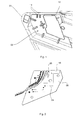
- a motor vehicle light comprises at least one by a in the Fig. 1 . Fig. 3 . Fig. 4, Fig. 5a) and Fig. 5b ) Luminaire housing 01 and a non-illustrated, the lamp housing 01 final lens enclosed luminaire interior 02.
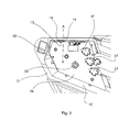
- the luminaire interior 02 accommodates at least one electronic component 03, the at least one in the Fig. 2 . Fig. 3 and Fig. 4 arranged, provided with conductor tracks 04, 05 illuminant carrier 06 is arranged and electrically contacted.
- the at least one component 03 may be part of an electronic circuit, comprise an electronic circuit or be comprised of an electronic circuit.
- one or more LEDs 07 can be arranged and electrically contacted on the illuminant carrier 06 as light sources of at least one light function of the motor vehicle luminaire.
- the LEDs 07 each comprise at least one LED chip.
- they may have an integrally formed, for example by injection molding, the LED chip completely or partially enveloping primary optics.
- the illuminant carrier 06 can, as in the Fig. 2 . Fig. 3 and Fig. 4 shown as a board executed. It is likewise conceivable to design the illuminant carrier 06 as an injection-molded circuit carrier produced in MID technology.
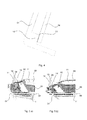
- the lamp interior 02 also houses at least one in the Fig. 5a) and Fig. 5b ), of the conductor tracks 04, 05 of the at least one illuminant carrier 06 different, electrically conductive surface 08.
- the at least one electrically conductive surface 08 is in the Fig. 5a) and Fig. 5b ), in contrast to a dark, electrically non-conductive surface 09 shown there.
- At least one in the Fig. 2 and Fig. 4 illustrated pad 10 made of an elastic, electrically conductive material provides the electrical contact of at least one of the tracks 04, 05 of the at least one illuminant 06 different electrically conductive surface 08 with at least one conductor 04, 05 of at least one illuminant carrier 06.
- the material of the pad 10 for example, be permanently elastic or permanently elastic curing.
- the pad 10 is preferably arranged such that during the assembly of a component comprising at least one electrically conductive surface 08, in this case the luminaire housing 01, and the at least one illuminant carrier 06, the electrical contact is made forcibly.
- the at least one of the conductor tracks 04, 05 of the at least one illuminant carrier 06 different electrically conductive surface 08 includes, for example, a coating.
- the coating is preferably a reflective coating intended for or forming a reflector 11.
- At least one of the conductor tracks 04, 05 of the at least one illuminant carrier 06 different, electrically conductive surface 08 is a one or more reflectors 11 forming ( Fig. 5a, Fig. 5b )), on one or more parts of the lamp interior 02 facing surface 12 ( Fig. 1 ) of the lamp housing 01 attached, reflective coating.
- the surface 12 facing the lamp interior 02 comprises the side of the lamp housing 01 facing the lamp interior 02.
- the pad 10 is preferably connected to the illuminant carrier 06.
- the pad 10 is in electrical contact with at least one conductor track 04, 05 of the illuminant carrier 06.
- the pad 10 is preferably provided with a light source designed for the electrical operation of at least one LED 07, for example Motor vehicle light provided conductor track 04, 05 of the illuminant carrier 06 in electrical connection.
- the pad 10 is adhesively bonded, for example, to the illuminant carrier 06 and / or to at least one conductor track 04, 05 of the illuminant carrier 06.
- the pad 10 may at least one in the Fig. 5a) and 5b ) Contact surface 13 shown to be assigned.
- the contact surface 13 is opposite the pad 10. If the pad 10 is located on the illuminant carrier 06, the contact surface on the electrically conductive surface 08 is located. If the pad 10 is located on the electrically conductive surface 08, the contact surface on the illuminant carrier 06 is located. Depending on whether the pad is on the illuminant carrier 06 or is provided on the electrically conductive surface 08, the contact surface 13 is electrically connected to at least one electrically conductive surface 08 or at least one conductor track 04, 05 of the illuminant carrier 06. In the Fig. 1 to 5 the contact surface with the electrically conductive surface 08 is electrically connected.
- At the pad 10 opposite and cooperating with this contact surface 13 may as in the Fig. 4, Fig. 5a) and Fig. 5b ) shown at least one pad 10 associated projection 14 may be provided.
- the surface of the projection 14 is like the contact surface 13 itself also part of the electrically conductive surface 08.
- the at least one projection 14 presses in the assembled state of the motor vehicle lamp, the pad 10 a ( Fig. 4 ) or cuts into it. As a result, a particularly reliable electrical contact is ensured.
- the invention is particularly industrially applicable in the field of production of motor vehicle lights.
Landscapes
- Engineering & Computer Science (AREA)
- General Engineering & Computer Science (AREA)
- Microelectronics & Electronic Packaging (AREA)
- Mechanical Engineering (AREA)
- Arrangements Of Lighting Devices For Vehicle Interiors, Mounting And Supporting Thereof, Circuits Therefore (AREA)
Priority Applications (1)
| Application Number | Priority Date | Filing Date | Title |
|---|---|---|---|
| SI201130397T SI2442018T1 (sl) | 2010-10-12 | 2011-09-21 | Luč motornega vozila |
Applications Claiming Priority (1)
| Application Number | Priority Date | Filing Date | Title |
|---|---|---|---|
| DE102010048236A DE102010048236A1 (de) | 2010-10-12 | 2010-10-12 | Kraftfahrzeugleuchte |
Publications (3)
| Publication Number | Publication Date |
|---|---|
| EP2442018A2 true EP2442018A2 (fr) | 2012-04-18 |
| EP2442018A3 EP2442018A3 (fr) | 2014-03-26 |
| EP2442018B1 EP2442018B1 (fr) | 2014-11-05 |
Family
ID=44651484
Family Applications (1)
| Application Number | Title | Priority Date | Filing Date |
|---|---|---|---|
| EP11182191.4A Active EP2442018B1 (fr) | 2010-10-12 | 2011-09-21 | Lampe de véhicule automobile |
Country Status (3)
| Country | Link |
|---|---|
| EP (1) | EP2442018B1 (fr) |
| DE (1) | DE102010048236A1 (fr) |
| SI (1) | SI2442018T1 (fr) |
Cited By (2)
| Publication number | Priority date | Publication date | Assignee | Title |
|---|---|---|---|---|
| EP3470729A1 (fr) * | 2017-10-10 | 2019-04-17 | Valeo Iluminacion | Dispositif d'éclairage |
| CN112874430A (zh) * | 2015-02-05 | 2021-06-01 | 法雷奥照明公司 | 用于将光源连接到电源装置的装置 |
Family Cites Families (7)
| Publication number | Priority date | Publication date | Assignee | Title |
|---|---|---|---|---|
| US4223368A (en) * | 1978-09-14 | 1980-09-16 | Dattilo Donald P | Electrostatic discharge protection device |
| US4334259A (en) * | 1980-08-11 | 1982-06-08 | Management Assistance Inc. | Discharge/ground button |
| US5536174A (en) * | 1994-09-29 | 1996-07-16 | Cooper Industries, Inc. | Lamp socket assembly for use with a backplate assembly and method of making same |
| US5796183A (en) * | 1996-01-31 | 1998-08-18 | Nartron Corporation | Capacitive responsive electronic switching circuit |
| JP3162290B2 (ja) * | 1996-04-30 | 2001-04-25 | 株式会社小糸製作所 | 放電バルブを有する車両用灯具 |
| US6156235A (en) * | 1997-11-10 | 2000-12-05 | World Properties, Inc. | Conductive elastomeric foams by in-situ vapor phase polymerization of pyrroles |
| FR2816035B1 (fr) * | 2000-10-30 | 2003-04-11 | Valeo Vision | Projecteur de vehicule automobile a moyens perfectionnes de blindage electromagnetique |
-
2010
- 2010-10-12 DE DE102010048236A patent/DE102010048236A1/de not_active Withdrawn
-
2011
- 2011-09-21 SI SI201130397T patent/SI2442018T1/sl unknown
- 2011-09-21 EP EP11182191.4A patent/EP2442018B1/fr active Active
Non-Patent Citations (1)
| Title |
|---|
| None |
Cited By (2)
| Publication number | Priority date | Publication date | Assignee | Title |
|---|---|---|---|---|
| CN112874430A (zh) * | 2015-02-05 | 2021-06-01 | 法雷奥照明公司 | 用于将光源连接到电源装置的装置 |
| EP3470729A1 (fr) * | 2017-10-10 | 2019-04-17 | Valeo Iluminacion | Dispositif d'éclairage |
Also Published As
| Publication number | Publication date |
|---|---|
| EP2442018A3 (fr) | 2014-03-26 |
| EP2442018B1 (fr) | 2014-11-05 |
| DE102010048236A1 (de) | 2012-04-12 |
| SI2442018T1 (sl) | 2015-04-30 |
Similar Documents
| Publication | Publication Date | Title |
|---|---|---|
| EP2179217B1 (fr) | Dispositif d'éclairage | |
| EP2178722B1 (fr) | Dispositif d'éclairage pour véhicules | |
| DE102009009087A1 (de) | Beleuchtungseinrichtung für ein Kraftfahrzeug | |
| EP3046399A1 (fr) | Mise en contact électrique d'une DELO et lampe de véhicule équipée d'une telle DELO à contact électrique | |
| EP2442018B1 (fr) | Lampe de véhicule automobile | |
| EP2938170A1 (fr) | Support pour diode lumineuse SMD | |
| DE102017217736B4 (de) | Animierbarer Kaskadenlichtleiter | |
| EP3026761A1 (fr) | Connexion enfichable directe destinée à la mise en contact électrique de supports de pistes conductrices souples dans des feux de véhicules | |
| EP2783915B1 (fr) | Procédé de génération d'un signal de diagnostic d'une lampe de véhicule automobile dotée de plusieurs moyens d'éclairage et lampe de véhicule automobile | |
| DE102014221815A1 (de) | Leuchtvorrichtung und Scheinwerfer für ein Kraftfahrzeug | |
| EP2999056A1 (fr) | Fiche de raccordement de mise en contact électrique de supports de pistes conductrices dans des dispositifs d'éclairage de véhicule, en particulier en platine à noyau métallique | |
| EP2664496A1 (fr) | Procédé destiné à la fabrication de lampes de véhicules automobiles | |
| EP2900038B1 (fr) | Agent lumineux et lampe de véhicule automobile équipée de celui-ci | |
| EP2900039B1 (fr) | Ampoule, phare de véhicule automobile équipé de celle-ci et son procédé de fonctionnement | |
| DE102009038523A1 (de) | Leuchtmittel sowie Leuchte | |
| EP2395281B1 (fr) | Lampe de véhicule automobile | |
| EP3553371A1 (fr) | Élément lumineux pour lampes de véhicule automobile comprenant un guide de lumière en forme de plaque et véhicule automobile équipé d'un tel élément lumineux | |
| EP3147554A1 (fr) | Une source lumineuse pour phares de vehicules comprenant delo et son procede de fabrication | |
| EP3193563A1 (fr) | Pour ampoule de feu de vehicule comprenant plusieurs sources lumineuses semi-conductrices et son procede de fonctionnement | |
| EP3677830A1 (fr) | Lampe pour véhicule et procédé de génération d'une surface lumineuse minimale dans une fonction d'éclairage d'une lampe pour véhicule | |
| EP2442627A1 (fr) | Lampe de véhicule automobile | |
| EP3026760A1 (fr) | Connexion enfichable directe destinée à la mise en contact électrique de supports de pistes conductrices souples dans des feux de véhicules | |
| DE102016218677A1 (de) | Beleuchtungsvorrichtung für ein Kraftfahrzeug | |
| EP3309854A1 (fr) | Moyen d'éclairage comprenant une delo pour phare de véhicule | |
| DE102015103037A1 (de) | Leuchtmittel und hiermit ausgestattete Fahrzeugleuchte |
Legal Events
| Date | Code | Title | Description |
|---|---|---|---|
| PUAI | Public reference made under article 153(3) epc to a published international application that has entered the european phase |
Free format text: ORIGINAL CODE: 0009012 |
|
| AK | Designated contracting states |
Kind code of ref document: A2 Designated state(s): AL AT BE BG CH CY CZ DE DK EE ES FI FR GB GR HR HU IE IS IT LI LT LU LV MC MK MT NL NO PL PT RO RS SE SI SK SM TR |
|
| AX | Request for extension of the european patent |
Extension state: BA ME |
|
| PUAL | Search report despatched |
Free format text: ORIGINAL CODE: 0009013 |
|
| AK | Designated contracting states |
Kind code of ref document: A3 Designated state(s): AL AT BE BG CH CY CZ DE DK EE ES FI FR GB GR HR HU IE IS IT LI LT LU LV MC MK MT NL NO PL PT RO RS SE SI SK SM TR |
|
| AX | Request for extension of the european patent |
Extension state: BA ME |
|
| RIC1 | Information provided on ipc code assigned before grant |
Ipc: H05F 3/02 20060101ALI20140218BHEP Ipc: B60Q 1/26 20060101ALI20140218BHEP Ipc: F21S 8/10 20060101AFI20140218BHEP Ipc: H05K 1/02 20060101ALI20140218BHEP Ipc: H05K 1/11 20060101ALI20140218BHEP |
|
| 17P | Request for examination filed |
Effective date: 20140319 |
|
| RBV | Designated contracting states (corrected) |
Designated state(s): AL AT BE BG CH CY CZ DE DK EE ES FI FR GB GR HR HU IE IS IT LI LT LU LV MC MK MT NL NO PL PT RO RS SE SI SK SM TR |
|
| REG | Reference to a national code |
Ref country code: DE Ref legal event code: R079 Ref document number: 502011004871 Country of ref document: DE Free format text: PREVIOUS MAIN CLASS: F21V0017000000 Ipc: F21S0008100000 |
|
| RIC1 | Information provided on ipc code assigned before grant |
Ipc: H05F 3/02 20060101ALI20140502BHEP Ipc: B60Q 1/26 20060101ALI20140502BHEP Ipc: H05K 1/11 20060101ALI20140502BHEP Ipc: F21S 8/10 20060101AFI20140502BHEP Ipc: H05K 1/02 20060101ALI20140502BHEP |
|
| GRAP | Despatch of communication of intention to grant a patent |
Free format text: ORIGINAL CODE: EPIDOSNIGR1 |
|
| INTG | Intention to grant announced |
Effective date: 20140616 |
|
| GRAS | Grant fee paid |
Free format text: ORIGINAL CODE: EPIDOSNIGR3 |
|
| GRAA | (expected) grant |
Free format text: ORIGINAL CODE: 0009210 |
|
| AK | Designated contracting states |
Kind code of ref document: B1 Designated state(s): AL AT BE BG CH CY CZ DE DK EE ES FI FR GB GR HR HU IE IS IT LI LT LU LV MC MK MT NL NO PL PT RO RS SE SI SK SM TR |
|
| REG | Reference to a national code |
Ref country code: GB Ref legal event code: FG4D Free format text: NOT ENGLISH |
|
| REG | Reference to a national code |
Ref country code: CH Ref legal event code: EP |
|
| REG | Reference to a national code |
Ref country code: AT Ref legal event code: REF Ref document number: 694834 Country of ref document: AT Kind code of ref document: T Effective date: 20141115 |
|
| REG | Reference to a national code |
Ref country code: IE Ref legal event code: FG4D Free format text: LANGUAGE OF EP DOCUMENT: GERMAN |
|
| REG | Reference to a national code |
Ref country code: DE Ref legal event code: R096 Ref document number: 502011004871 Country of ref document: DE Effective date: 20141218 |
|
| REG | Reference to a national code |
Ref country code: DE Ref legal event code: R082 Ref document number: 502011004871 Country of ref document: DE Representative=s name: BENNINGER PATENTANWALTSKANZLEI, DE |
|
| REG | Reference to a national code |
Ref country code: NL Ref legal event code: VDEP Effective date: 20141105 |
|
| RAP2 | Party data changed (patent owner data changed or rights of a patent transferred) |
Owner name: ODELO GMBH |
|
| REG | Reference to a national code |
Ref country code: DE Ref legal event code: R081 Ref document number: 502011004871 Country of ref document: DE Owner name: ODELO GMBH, DE Free format text: FORMER OWNER: ODELO GMBH, 71409 SCHWAIKHEIM, DE Effective date: 20150302 Ref country code: DE Ref legal event code: R082 Ref document number: 502011004871 Country of ref document: DE Representative=s name: BENNINGER PATENTANWALTSKANZLEI, DE Effective date: 20150302 |
|
| REG | Reference to a national code |
Ref country code: LT Ref legal event code: MG4D |
|
| PG25 | Lapsed in a contracting state [announced via postgrant information from national office to epo] |
Ref country code: FI Free format text: LAPSE BECAUSE OF FAILURE TO SUBMIT A TRANSLATION OF THE DESCRIPTION OR TO PAY THE FEE WITHIN THE PRESCRIBED TIME-LIMIT Effective date: 20141105 Ref country code: LT Free format text: LAPSE BECAUSE OF FAILURE TO SUBMIT A TRANSLATION OF THE DESCRIPTION OR TO PAY THE FEE WITHIN THE PRESCRIBED TIME-LIMIT Effective date: 20141105 Ref country code: NO Free format text: LAPSE BECAUSE OF FAILURE TO SUBMIT A TRANSLATION OF THE DESCRIPTION OR TO PAY THE FEE WITHIN THE PRESCRIBED TIME-LIMIT Effective date: 20150205 Ref country code: PT Free format text: LAPSE BECAUSE OF FAILURE TO SUBMIT A TRANSLATION OF THE DESCRIPTION OR TO PAY THE FEE WITHIN THE PRESCRIBED TIME-LIMIT Effective date: 20150305 Ref country code: NL Free format text: LAPSE BECAUSE OF FAILURE TO SUBMIT A TRANSLATION OF THE DESCRIPTION OR TO PAY THE FEE WITHIN THE PRESCRIBED TIME-LIMIT Effective date: 20141105 Ref country code: ES Free format text: LAPSE BECAUSE OF FAILURE TO SUBMIT A TRANSLATION OF THE DESCRIPTION OR TO PAY THE FEE WITHIN THE PRESCRIBED TIME-LIMIT Effective date: 20141105 Ref country code: IS Free format text: LAPSE BECAUSE OF FAILURE TO SUBMIT A TRANSLATION OF THE DESCRIPTION OR TO PAY THE FEE WITHIN THE PRESCRIBED TIME-LIMIT Effective date: 20150305 |
|
| PG25 | Lapsed in a contracting state [announced via postgrant information from national office to epo] |
Ref country code: RS Free format text: LAPSE BECAUSE OF FAILURE TO SUBMIT A TRANSLATION OF THE DESCRIPTION OR TO PAY THE FEE WITHIN THE PRESCRIBED TIME-LIMIT Effective date: 20141105 Ref country code: HR Free format text: LAPSE BECAUSE OF FAILURE TO SUBMIT A TRANSLATION OF THE DESCRIPTION OR TO PAY THE FEE WITHIN THE PRESCRIBED TIME-LIMIT Effective date: 20141105 Ref country code: GR Free format text: LAPSE BECAUSE OF FAILURE TO SUBMIT A TRANSLATION OF THE DESCRIPTION OR TO PAY THE FEE WITHIN THE PRESCRIBED TIME-LIMIT Effective date: 20150206 Ref country code: LV Free format text: LAPSE BECAUSE OF FAILURE TO SUBMIT A TRANSLATION OF THE DESCRIPTION OR TO PAY THE FEE WITHIN THE PRESCRIBED TIME-LIMIT Effective date: 20141105 Ref country code: CY Free format text: LAPSE BECAUSE OF FAILURE TO SUBMIT A TRANSLATION OF THE DESCRIPTION OR TO PAY THE FEE WITHIN THE PRESCRIBED TIME-LIMIT Effective date: 20141105 Ref country code: SE Free format text: LAPSE BECAUSE OF FAILURE TO SUBMIT A TRANSLATION OF THE DESCRIPTION OR TO PAY THE FEE WITHIN THE PRESCRIBED TIME-LIMIT Effective date: 20141105 Ref country code: PL Free format text: LAPSE BECAUSE OF FAILURE TO SUBMIT A TRANSLATION OF THE DESCRIPTION OR TO PAY THE FEE WITHIN THE PRESCRIBED TIME-LIMIT Effective date: 20141105 |
|
| PG25 | Lapsed in a contracting state [announced via postgrant information from national office to epo] |
Ref country code: DK Free format text: LAPSE BECAUSE OF FAILURE TO SUBMIT A TRANSLATION OF THE DESCRIPTION OR TO PAY THE FEE WITHIN THE PRESCRIBED TIME-LIMIT Effective date: 20141105 Ref country code: SK Free format text: LAPSE BECAUSE OF FAILURE TO SUBMIT A TRANSLATION OF THE DESCRIPTION OR TO PAY THE FEE WITHIN THE PRESCRIBED TIME-LIMIT Effective date: 20141105 Ref country code: EE Free format text: LAPSE BECAUSE OF FAILURE TO SUBMIT A TRANSLATION OF THE DESCRIPTION OR TO PAY THE FEE WITHIN THE PRESCRIBED TIME-LIMIT Effective date: 20141105 Ref country code: CZ Free format text: LAPSE BECAUSE OF FAILURE TO SUBMIT A TRANSLATION OF THE DESCRIPTION OR TO PAY THE FEE WITHIN THE PRESCRIBED TIME-LIMIT Effective date: 20141105 |
|
| REG | Reference to a national code |
Ref country code: DE Ref legal event code: R097 Ref document number: 502011004871 Country of ref document: DE |
|
| PLBE | No opposition filed within time limit |
Free format text: ORIGINAL CODE: 0009261 |
|
| STAA | Information on the status of an ep patent application or granted ep patent |
Free format text: STATUS: NO OPPOSITION FILED WITHIN TIME LIMIT |
|
| 26N | No opposition filed |
Effective date: 20150806 |
|
| PG25 | Lapsed in a contracting state [announced via postgrant information from national office to epo] |
Ref country code: IT Free format text: LAPSE BECAUSE OF FAILURE TO SUBMIT A TRANSLATION OF THE DESCRIPTION OR TO PAY THE FEE WITHIN THE PRESCRIBED TIME-LIMIT Effective date: 20141105 |
|
| PG25 | Lapsed in a contracting state [announced via postgrant information from national office to epo] |
Ref country code: MC Free format text: LAPSE BECAUSE OF FAILURE TO SUBMIT A TRANSLATION OF THE DESCRIPTION OR TO PAY THE FEE WITHIN THE PRESCRIBED TIME-LIMIT Effective date: 20141105 Ref country code: LU Free format text: LAPSE BECAUSE OF FAILURE TO SUBMIT A TRANSLATION OF THE DESCRIPTION OR TO PAY THE FEE WITHIN THE PRESCRIBED TIME-LIMIT Effective date: 20150921 |
|
| REG | Reference to a national code |
Ref country code: CH Ref legal event code: PL |
|
| GBPC | Gb: european patent ceased through non-payment of renewal fee |
Effective date: 20150921 |
|
| PG25 | Lapsed in a contracting state [announced via postgrant information from national office to epo] |
Ref country code: RO Free format text: LAPSE BECAUSE OF FAILURE TO SUBMIT A TRANSLATION OF THE DESCRIPTION OR TO PAY THE FEE WITHIN THE PRESCRIBED TIME-LIMIT Effective date: 20141105 |
|
| REG | Reference to a national code |
Ref country code: IE Ref legal event code: MM4A |
|
| PG25 | Lapsed in a contracting state [announced via postgrant information from national office to epo] |
Ref country code: GB Free format text: LAPSE BECAUSE OF NON-PAYMENT OF DUE FEES Effective date: 20150921 Ref country code: LI Free format text: LAPSE BECAUSE OF NON-PAYMENT OF DUE FEES Effective date: 20150930 Ref country code: CH Free format text: LAPSE BECAUSE OF NON-PAYMENT OF DUE FEES Effective date: 20150930 Ref country code: IE Free format text: LAPSE BECAUSE OF NON-PAYMENT OF DUE FEES Effective date: 20150921 |
|
| REG | Reference to a national code |
Ref country code: FR Ref legal event code: PLFP Year of fee payment: 6 |
|
| PG25 | Lapsed in a contracting state [announced via postgrant information from national office to epo] |
Ref country code: MT Free format text: LAPSE BECAUSE OF FAILURE TO SUBMIT A TRANSLATION OF THE DESCRIPTION OR TO PAY THE FEE WITHIN THE PRESCRIBED TIME-LIMIT Effective date: 20141105 |
|
| PG25 | Lapsed in a contracting state [announced via postgrant information from national office to epo] |
Ref country code: BG Free format text: LAPSE BECAUSE OF FAILURE TO SUBMIT A TRANSLATION OF THE DESCRIPTION OR TO PAY THE FEE WITHIN THE PRESCRIBED TIME-LIMIT Effective date: 20141105 Ref country code: SM Free format text: LAPSE BECAUSE OF FAILURE TO SUBMIT A TRANSLATION OF THE DESCRIPTION OR TO PAY THE FEE WITHIN THE PRESCRIBED TIME-LIMIT Effective date: 20141105 Ref country code: HU Free format text: LAPSE BECAUSE OF FAILURE TO SUBMIT A TRANSLATION OF THE DESCRIPTION OR TO PAY THE FEE WITHIN THE PRESCRIBED TIME-LIMIT; INVALID AB INITIO Effective date: 20110921 |
|
| PG25 | Lapsed in a contracting state [announced via postgrant information from national office to epo] |
Ref country code: BE Free format text: LAPSE BECAUSE OF NON-PAYMENT OF DUE FEES Effective date: 20150930 |
|
| PG25 | Lapsed in a contracting state [announced via postgrant information from national office to epo] |
Ref country code: TR Free format text: LAPSE BECAUSE OF FAILURE TO SUBMIT A TRANSLATION OF THE DESCRIPTION OR TO PAY THE FEE WITHIN THE PRESCRIBED TIME-LIMIT Effective date: 20141105 |
|
| REG | Reference to a national code |
Ref country code: FR Ref legal event code: PLFP Year of fee payment: 7 |
|
| REG | Reference to a national code |
Ref country code: AT Ref legal event code: MM01 Ref document number: 694834 Country of ref document: AT Kind code of ref document: T Effective date: 20160921 |
|
| REG | Reference to a national code |
Ref country code: DE Ref legal event code: R079 Ref document number: 502011004871 Country of ref document: DE Free format text: PREVIOUS MAIN CLASS: F21S0008100000 Ipc: F21S0043000000 |
|
| PG25 | Lapsed in a contracting state [announced via postgrant information from national office to epo] |
Ref country code: AT Free format text: LAPSE BECAUSE OF NON-PAYMENT OF DUE FEES Effective date: 20160921 |
|
| PG25 | Lapsed in a contracting state [announced via postgrant information from national office to epo] |
Ref country code: MK Free format text: LAPSE BECAUSE OF FAILURE TO SUBMIT A TRANSLATION OF THE DESCRIPTION OR TO PAY THE FEE WITHIN THE PRESCRIBED TIME-LIMIT Effective date: 20141105 |
|
| REG | Reference to a national code |
Ref country code: FR Ref legal event code: PLFP Year of fee payment: 8 |
|
| PG25 | Lapsed in a contracting state [announced via postgrant information from national office to epo] |
Ref country code: AL Free format text: LAPSE BECAUSE OF FAILURE TO SUBMIT A TRANSLATION OF THE DESCRIPTION OR TO PAY THE FEE WITHIN THE PRESCRIBED TIME-LIMIT Effective date: 20141105 |
|
| REG | Reference to a national code |
Ref country code: DE Ref legal event code: R082 Ref document number: 502011004871 Country of ref document: DE Representative=s name: BENNINGER, JOHANNES, DIPL.-ING., DE |
|
| PGFP | Annual fee paid to national office [announced via postgrant information from national office to epo] |
Ref country code: DE Payment date: 20250919 Year of fee payment: 15 |
|
| PGFP | Annual fee paid to national office [announced via postgrant information from national office to epo] |
Ref country code: FR Payment date: 20250922 Year of fee payment: 15 |
|
| PGFP | Annual fee paid to national office [announced via postgrant information from national office to epo] |
Ref country code: SI Payment date: 20250911 Year of fee payment: 15 |