EP2455108A1 - Duftspender - Google Patents
Duftspender Download PDFInfo
- Publication number
- EP2455108A1 EP2455108A1 EP11010182A EP11010182A EP2455108A1 EP 2455108 A1 EP2455108 A1 EP 2455108A1 EP 11010182 A EP11010182 A EP 11010182A EP 11010182 A EP11010182 A EP 11010182A EP 2455108 A1 EP2455108 A1 EP 2455108A1
- Authority
- EP
- European Patent Office
- Prior art keywords
- fragrance
- source
- fan
- wick
- disperser
- Prior art date
- Legal status (The legal status is an assumption and is not a legal conclusion. Google has not performed a legal analysis and makes no representation as to the accuracy of the status listed.)
- Granted
Links
Images








Classifications
-
- A—HUMAN NECESSITIES
- A61—MEDICAL OR VETERINARY SCIENCE; HYGIENE
- A61L—METHODS OR APPARATUS FOR STERILISING MATERIALS OR OBJECTS IN GENERAL; DISINFECTION, STERILISATION OR DEODORISATION OF AIR; CHEMICAL ASPECTS OF BANDAGES, DRESSINGS, ABSORBENT PADS OR SURGICAL ARTICLES; MATERIALS FOR BANDAGES, DRESSINGS, ABSORBENT PADS OR SURGICAL ARTICLES
- A61L9/00—Disinfection, sterilisation or deodorisation of air
- A61L9/015—Disinfection, sterilisation or deodorisation of air using gaseous or vaporous substances, e.g. ozone
- A61L9/02—Disinfection, sterilisation or deodorisation of air using gaseous or vaporous substances, e.g. ozone using substances evaporated in the air by heating or combustion
- A61L9/03—Apparatus therefor
- A61L9/037—Apparatus therefor comprising a wick
-
- A—HUMAN NECESSITIES
- A61—MEDICAL OR VETERINARY SCIENCE; HYGIENE
- A61L—METHODS OR APPARATUS FOR STERILISING MATERIALS OR OBJECTS IN GENERAL; DISINFECTION, STERILISATION OR DEODORISATION OF AIR; CHEMICAL ASPECTS OF BANDAGES, DRESSINGS, ABSORBENT PADS OR SURGICAL ARTICLES; MATERIALS FOR BANDAGES, DRESSINGS, ABSORBENT PADS OR SURGICAL ARTICLES
- A61L9/00—Disinfection, sterilisation or deodorisation of air
- A61L9/015—Disinfection, sterilisation or deodorisation of air using gaseous or vaporous substances, e.g. ozone
- A61L9/02—Disinfection, sterilisation or deodorisation of air using gaseous or vaporous substances, e.g. ozone using substances evaporated in the air by heating or combustion
-
- A—HUMAN NECESSITIES
- A61—MEDICAL OR VETERINARY SCIENCE; HYGIENE
- A61L—METHODS OR APPARATUS FOR STERILISING MATERIALS OR OBJECTS IN GENERAL; DISINFECTION, STERILISATION OR DEODORISATION OF AIR; CHEMICAL ASPECTS OF BANDAGES, DRESSINGS, ABSORBENT PADS OR SURGICAL ARTICLES; MATERIALS FOR BANDAGES, DRESSINGS, ABSORBENT PADS OR SURGICAL ARTICLES
- A61L9/00—Disinfection, sterilisation or deodorisation of air
- A61L9/015—Disinfection, sterilisation or deodorisation of air using gaseous or vaporous substances, e.g. ozone
- A61L9/02—Disinfection, sterilisation or deodorisation of air using gaseous or vaporous substances, e.g. ozone using substances evaporated in the air by heating or combustion
- A61L9/03—Apparatus therefor
- A61L9/035—Apparatus therefor emanating multiple odours
-
- A—HUMAN NECESSITIES
- A61—MEDICAL OR VETERINARY SCIENCE; HYGIENE
- A61L—METHODS OR APPARATUS FOR STERILISING MATERIALS OR OBJECTS IN GENERAL; DISINFECTION, STERILISATION OR DEODORISATION OF AIR; CHEMICAL ASPECTS OF BANDAGES, DRESSINGS, ABSORBENT PADS OR SURGICAL ARTICLES; MATERIALS FOR BANDAGES, DRESSINGS, ABSORBENT PADS OR SURGICAL ARTICLES
- A61L9/00—Disinfection, sterilisation or deodorisation of air
- A61L9/015—Disinfection, sterilisation or deodorisation of air using gaseous or vaporous substances, e.g. ozone
- A61L9/04—Disinfection, sterilisation or deodorisation of air using gaseous or vaporous substances, e.g. ozone using substances evaporated in the air without heating
-
- A—HUMAN NECESSITIES
- A61—MEDICAL OR VETERINARY SCIENCE; HYGIENE
- A61L—METHODS OR APPARATUS FOR STERILISING MATERIALS OR OBJECTS IN GENERAL; DISINFECTION, STERILISATION OR DEODORISATION OF AIR; CHEMICAL ASPECTS OF BANDAGES, DRESSINGS, ABSORBENT PADS OR SURGICAL ARTICLES; MATERIALS FOR BANDAGES, DRESSINGS, ABSORBENT PADS OR SURGICAL ARTICLES
- A61L9/00—Disinfection, sterilisation or deodorisation of air
- A61L9/015—Disinfection, sterilisation or deodorisation of air using gaseous or vaporous substances, e.g. ozone
- A61L9/04—Disinfection, sterilisation or deodorisation of air using gaseous or vaporous substances, e.g. ozone using substances evaporated in the air without heating
- A61L9/042—Disinfection, sterilisation or deodorisation of air using gaseous or vaporous substances, e.g. ozone using substances evaporated in the air without heating with the help of a macromolecular compound as a carrier or diluent
-
- A—HUMAN NECESSITIES
- A61—MEDICAL OR VETERINARY SCIENCE; HYGIENE
- A61L—METHODS OR APPARATUS FOR STERILISING MATERIALS OR OBJECTS IN GENERAL; DISINFECTION, STERILISATION OR DEODORISATION OF AIR; CHEMICAL ASPECTS OF BANDAGES, DRESSINGS, ABSORBENT PADS OR SURGICAL ARTICLES; MATERIALS FOR BANDAGES, DRESSINGS, ABSORBENT PADS OR SURGICAL ARTICLES
- A61L9/00—Disinfection, sterilisation or deodorisation of air
- A61L9/015—Disinfection, sterilisation or deodorisation of air using gaseous or vaporous substances, e.g. ozone
- A61L9/04—Disinfection, sterilisation or deodorisation of air using gaseous or vaporous substances, e.g. ozone using substances evaporated in the air without heating
- A61L9/12—Apparatus, e.g. holders, therefor
- A61L9/122—Apparatus, e.g. holders, therefor comprising a fan
-
- A—HUMAN NECESSITIES
- A61—MEDICAL OR VETERINARY SCIENCE; HYGIENE
- A61L—METHODS OR APPARATUS FOR STERILISING MATERIALS OR OBJECTS IN GENERAL; DISINFECTION, STERILISATION OR DEODORISATION OF AIR; CHEMICAL ASPECTS OF BANDAGES, DRESSINGS, ABSORBENT PADS OR SURGICAL ARTICLES; MATERIALS FOR BANDAGES, DRESSINGS, ABSORBENT PADS OR SURGICAL ARTICLES
- A61L9/00—Disinfection, sterilisation or deodorisation of air
- A61L9/015—Disinfection, sterilisation or deodorisation of air using gaseous or vaporous substances, e.g. ozone
- A61L9/04—Disinfection, sterilisation or deodorisation of air using gaseous or vaporous substances, e.g. ozone using substances evaporated in the air without heating
- A61L9/12—Apparatus, e.g. holders, therefor
- A61L9/127—Apparatus, e.g. holders, therefor comprising a wick
-
- Y—GENERAL TAGGING OF NEW TECHNOLOGICAL DEVELOPMENTS; GENERAL TAGGING OF CROSS-SECTIONAL TECHNOLOGIES SPANNING OVER SEVERAL SECTIONS OF THE IPC; TECHNICAL SUBJECTS COVERED BY FORMER USPC CROSS-REFERENCE ART COLLECTIONS [XRACs] AND DIGESTS
- Y10—TECHNICAL SUBJECTS COVERED BY FORMER USPC
- Y10S—TECHNICAL SUBJECTS COVERED BY FORMER USPC CROSS-REFERENCE ART COLLECTIONS [XRACs] AND DIGESTS
- Y10S261/00—Gas and liquid contact apparatus
- Y10S261/88—Aroma dispensers
-
- Y—GENERAL TAGGING OF NEW TECHNOLOGICAL DEVELOPMENTS; GENERAL TAGGING OF CROSS-SECTIONAL TECHNOLOGIES SPANNING OVER SEVERAL SECTIONS OF THE IPC; TECHNICAL SUBJECTS COVERED BY FORMER USPC CROSS-REFERENCE ART COLLECTIONS [XRACs] AND DIGESTS
- Y10—TECHNICAL SUBJECTS COVERED BY FORMER USPC
- Y10S—TECHNICAL SUBJECTS COVERED BY FORMER USPC CROSS-REFERENCE ART COLLECTIONS [XRACs] AND DIGESTS
- Y10S261/00—Gas and liquid contact apparatus
- Y10S261/88—Aroma dispensers
- Y10S261/89—Electrically heated aroma dispensers
Definitions
- the invention relates to fragrance dispersers, fragrance sources and fragrance containers.
- Fragrance dispersers are used to release one or more fragrances into an enclosed space such as a room.
- the fragrance is held by a fragrance source and released either by natural convection or by forced convection or by heating a wick or pad, for example, holding the fragrance.
- a fragrance disperser comprising a source of fragrance and means for generating a flow of air to release said fragrance.
- fragrance source is a container containing a liquid fragrance.
- the fragrance is released by a convection air current passing across an outlet for the fragrance. It is a problem that this does not provide a directed flow of air.
- a fragrance container comprising a reservoir for receiving a liquid fragrance and an outlet to the reservoir, the outlet defining a path for a flow of air to release fragrance in the reservoir.
- Many fragrance sources are complicated to manufacture including separate containers and wicks.
- a fragrance source comprising a back sheet and a front sheet with a wicking material therebetween the back sheet and the front sheet being joined together along a closed line to define a reservoir for fragrance, a portion of the wicking material being exposable outside the closed line for releasing the fragrance, the join being such as to allow the wicking material to wick fragrance from the reservoir to the exposable portion.
- a fragrance disperser comprising two sources of fragrance, means for dispersing fragrance from said sources and a control system for controlling said dispersing means.
- the fragrance disperser is formed by a housing 10, a fan 11 and a fragrance source 12.
- the housing 10 which may be formed of any suitable material such as metal or plastics, is formed by a back wall 13, a side wall 14 and a front cover 15 (seen in Figure 3 ).
- the back wall 13 is generally rectangular with parallel side edges 16 interconnected at one end by a straight lower end edge 17 and at the other end by a generally semi-circular end edge 18.
- the side wall 14 extends around the side edges 16 and the semi-circular upper end edge 18.
- the portion of the side wall 14 extending around the upper end edge 18 has an interior surface 19 (see Figures 1 and 2 ) formed by two-part spirals that meet at the apex of the end edge 18 and increase in radius from that point.
- This portion of the housing contains the fan 11 which is connected to a motor 21 by a drive shaft 22 (see Figure 3 ).
- the motor 21 is connected to, and controlled by, a control board 23 mounted on the back wall 13.
- the fragrance source 12 is also carried by the back wall 13 below the fan 11. The construction of this fragrance source 12 will be described in more detail below.
- the front of the housing 10 is closed by the front cover 15 seen in Figures 3 and 4 .
- the cover 15 has generally the same shape as the back wall 13 but is provided with an air inlet 26 aligned with the fan 11.
- the cover is provided with an inwardly slanted wall 27 and a central divider 28.
- the wall 27 and the divider 28 form a pair of side-by-side ducts 29a,29b that converge as they extend away from the fan 11 and terminate in respective outlets one of which is shown at 30 in Figure 3 .
- the position of the divider 28 in relation to the fragrance source 12 will be discussed below.
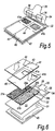
- the fragrance source 12 is shown in more detail in Figures 5 and 6 .
- the fragrance source 12 comprises a back sheet 31 which is of generally rectangular shape and may be formed, for example, from a plastics laminate.
- the back sheet 31 is provided with a lateral fold line 32 which divides the back sheet 31 into a main portion 33 and a flap 34.
- the end of the flap 34 is provided with a tab 35 and the surface of the flap on the inner side of the fold line 32 is provided with two adhesive frames 36 whose function will be described below.
- First and second strips 37a,37b of wick material are placed on the inner surface of the main portion 33 of the back sheet 31.
- Each strip of wick material 37a,37b is of elongate rectangular shape provided towards one end with a pair of inwardly directed registering notches 39a,39b whose function will be described below.
- the first and second strips 37a,37b are arranged side-by-side and parallel to one another.
- the first and second strips 37a,37b are covered by a front sheet 40 that may also be of a plastics laminate and is the same size as the main portion 33 of the back sheet 31.
- the front sheet 40 is formed towards one edge with two windows 41a,41b. Each window is in register with a respective shorter portion of an associated one of the first and second strips 37a,37b between the notches 39a,39b and the adjacent end of the associated strip 37a,37b.
- the front sheet 40 may be formed in one-piece with the back sheet 31, extending from the edge of the back sheet 31 opposite the fold line 32.
- the front sheet 40 when not formed in one-piece with the back sheet, is then connected to the back sheet along lines 42,43,44 by, for example, welding or gluing.
- the first connection line 42 is a rectangular line extending around the peripheries of the main portion 33 and the front sheet 40 and thus forms a closed chamber between these parts 33,40.
- the second connection line 43 is a longitudinal line which extends along the gap between the first and second strips 37a,37b thus sub-dividing the main chamber to form separate chambers each containing a respective strip 37a,37b.
- the third connection line 44 is a lateral line extending between the side edges of the main portion 33 and the front sheet 40 with the line 44 extending into the notches 39a,39b and being interrupted between the notches 39a,39b.
- each sub-chamber containing an associated strip 37a,37b is divided into a larger portion and a smaller portion separated by a neck with the smaller portion underlying an associated window 41a,41b.
- each larger portion of each sub-chamber is filled with a respective different liquid fragrance.
- the flap 34 is folded over the windows 41a,41b with the adhesive frames 36 sealing around the peripheries of the windows 41a,41b to close the windows 41a,41b.
- a source of electric power 45 This may be a flat dry cell battery.
- the fragrance source 12 is opened by pulling the tab 35 to open the peelable seal formed by the adhesive frames 36.
- the fragrance source 12 is then mounted in the housing 10 as briefly described above.
- the windows 41a,41b are, as seen in Figures 1 and 2 , adjacent the outlets 30 with the divider 28 extending along the longitudinal connecting line 43 so that each window 41a,41b is in a respective duct 29a,29b.
- Each fragrance wicks to the associated window 41a,41b at a rate controlled both by the characteristics of the strips 37a,37b and the gaps between the notches 39a,39b.
- the source of electric power 45 includes contacts which connect the source of electric power 45 to the control system 23 for the motor 21 of the fan 11.
- the motor 21 operates when connected to the source of electric power 45 and the fan 11 rotates in, for example, the clockwise direction shown in Figure 1 .
- This produces an air flow through the duct 29a associated with the first window 41a and so conveys the associated fragrance to the surrounding atmosphere.
- the convergence of the duct 29a towards the associated outlet 30 increases the speed of the air as it passes across the window 41a.
- control system 23 After a period of time, the control system 23 reverses the direction of rotation of the fan 11 so that it rotates in an anti-clockwise direction as shown in Figure 2 . The effect of this is to pass air along the duct 29b and across the window 41b so releasing the associated fragrance through the outlet 30 into the surrounding atmosphere.
- T1 is the time for which the fan 11 rotates in, for example, the clockwise direction. This time is designed to allow the concentration of the first fragrance to reach a maximum.
- the dwell period T2 is designed to allow the first fragrance to disperse before the second fragrance is emitted.
- T3 is the time for which the fan rotates in, for example, an anti-clockwise direction to emit the second fragrance and allow it to reach a maximum and T4 is the dwell period that allows the second fragrance to disperse.
- T4 is the dwell period that allows the second fragrance to disperse.
- the time for which each wick is inactive allows the fragrance to wick to the associated window for immediate evaporation when the wick becomes active. As will be seen, these intervals need not be equal.
- fragrances may be varied depending on the fragrance.
- There is a known phenomenon called olfactory fatigue where, after a time a person smelling a fragrance at a stable concentration becomes unaware of the smell. This time varies from fragrance to fragrance and the intervals mentioned above may be adjusted in accordance with those times. In addition, the time intervals may be able to be manually adjusted by the user. Further, the control system could be programmed to accommodate small or large rooms or to provide a booster fragrance on demand.
- the timing may be altered for different sized rooms in a number of different ways. For example, for a larger sized room, it may be desirable to increase the on times T1, T3 for fragrances 1 and 2 whilst leaving the off times T2, T4 (the dwell periods) unchanged. Alternatively, the cycle could be altered by leaving the on times T1, T3 unchanged but shortening the dwell periods T2, T4. Another possibility is to increase both the on and off times whilst keeping the on/off ratio unchanged. Similarly for smaller rooms it may be desirable to reduce the on times T1, T3 only, or to increase the dwell periods T2, T4 only, or to shorten both whilst maintaining the same ratio.
- the fragrance source 12 When the fragrance source 12 is finished, it can be replaced by a new fragrance source 12 on an associated source of electric power 45.
- the power of the source 45 is matched to the volume of fragrance so that when the power of the source is running low the amount of fragrance remaining is also running low.
- the control system 23 may monitor battery power and provide an indication when the power is running low so providing an indication that the fragrance is close to exhaustion and requires replacement.
- the indication may be a visual indication provided, for example, by an LED on the housing 10.
- a second form of fragrance source for use with the fragrance disperser of Figures 1 and 2 is shown in Figures 8 and 9 .
- the second fragrance source 46 is formed by a rectangular back sheet 47 which may be of a plastics laminate and a similar shaped front sheet 48 of the same material.
- Two valve inserts 49a,49b are also provided.
- Each valve insert 49a,49b is formed by a short section of tube 50a,50b and a pair of diametrically opposed outwardly extending wings 51a,51b.
- Each tube 50a,50b contains a pierceable seal (not shown).
- the back sheet 47 is placed beneath the front sheet 48 with the valve inserts 49a,49b spaced apart along registering edges of the sheets 47,48.
- the sheets 47,48 are then connected together along lines 53,54 by, for example, welding or gluing.
- the first line 53 extends around the peripheries of the back sheet 47 and the front sheet 48 and also connects to the wings 51a,51b and the tubes 50a,50b of the valve inserts 49a,49b.
- the second line 54 is a longitudinal line extending between the edge of the sheets 47,48 including the valve inserts 49a,49b and the opposite edge.
- the back sheet 47 and the front sheet 48 thus form between them a chamber which is sub-divided by the longitudinal line into two sub-chambers. Each chamber contains an associated different liquid fragrance.
- the second fragrance source 46 also includes two inserts 55a,55b.
- Each insert 55a,55b is formed by a generally rectangular area of wick material and an elongate capillary connector 57a,57b projecting from the associated wick material 56a,56b.
- each capillary connector 57a,57b is inserted through an associated seal of a valve insert 49a,49b to reach the fragrances in the sub-chambers.
- the fragrances pass along the capillary connectors 57a,57b to the associated wick materials 56a,56b where they evaporate.
- the second fragrance source 46 may be mounted and used with the fragrance disperser as described above with reference to Figures 1 to 4 .
- the second form of fragrance disperser has parts common to the fragrance disperser of Figures 1 to 4 . Those parts will be given the same reference numerals as the corresponding parts in Figures 1 to 4 and will not be described in detail.
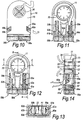
- the fragrance is supplied by two containers 58a,58b.
- Each container 58a,58b is connected to the housing 10 in a manner to be described below and includes a projecting wick 59a,59b received in an associated shaped duct 60a,60b formed in the housing 10.
- Each container 58a,58b is formed with a neck 61a,61b surrounding a mouth 62a,62b. Each neck has an outwardly directing flange 63a,63b and the associated wick 59a,59b extends out of each mouth 62a,62b.
- the housing is formed at the lower end edge 17 with two apertures 64a,64b each for receiving the neck 61 of the associated container 58a,58b. As seen particularly in Figure 14 , each aperture 64a,64b includes a retention mechanism for holding the associated container 58a,58b connected to the housing 10.
- the retention mechanism is formed by an inwardly directed projection 65 that extends under the flange 63a,63b of the associated container 58a,58b and a peg 66 that retracts against a spring 67 as the neck 61a,61b is pushed into the associated aperture 64a,64b to allow the flange 63a,63b to pass the peg 66 and then is forced outwardly by the spring 67 to engage behind the flange 63a,63b to hold the associated container 58a,58b in position.
- Each shaped duct 60a,60b extends from a respective side of the fan 11 initially in a direction tangential to the fan 11. Then, as seen in Figure 14 the duct 60a,60b turns through 90° to terminate in an outlet 68a,68b on the cover 15. As seen in Figures 11, 12 and 14 , each wick 59a,59b extends along the associated duct 60a,60b to terminate adjacent the periphery of the fan 11.
- the fan 11 is associated with a shutter 69 which is carried on the drive shaft 22 and includes an arcuate wall 70.
- the second fragrance disperser described above with reference to Figures 10 to 14 operates broadly as described above with reference to Figures 1 to 4 .
- Air from the fan passes along one or other of the shaped ducts 60a,60b and evaporates fragrance from the associated wick 59a,59b which then passes out of the associated outlet 68a,68b into the surrounding atmosphere.
- the shape of the duct 60a,60b ensures that air from the fan 11 does not pass simply axially along the wicks 59a,59b. Rather, the shape of the ducts 60a,60b results in a circumferential flow of air around the wicks 59a,59b. This results in more efficient evaporation of fragrance from the wicks 59a,59b.
- Power for the motor 21 is provided from an external power supply such as a battery (not shown) or a source of mains power.
- the housing 10 is provided with three control buttons 111,112,113.
- the timing protocol is altered to be suitable for smaller rooms.
- Pressing the button 112 alters the timing protocol to be suitable for larger rooms.
- Pressing the button 113 alters the timing protocol for a set limited period of time. For that limited period of time, the volume of fragrance emitted is increased. This provides a boost of fragrance.
- the speed of the fan 11 could be increased or decreased to alter the volume of fragrance emitted. This could be achieved by the varying power supplied to the motor.
- each duct opening 68a,68b is controlled by a respective shutter assembly 210a,210b.
- Each assembly 210a,210b comprises a shutter 211a,211b to which is connected a peg 212a,212b which is slidably movable in a vertical slot 213a,213b in the front cover 15 of the disperser, such that when the peg 212a,212b is at the top of the slot 213a,213b the shutter is in a fully open position and the duct opening 68a,68b is a maximum size, and when the peg is at the bottom of the slot the shutter is in a fully closed position and the duct opening is a minimum size. This may correspond to completely closing off the duct opening 68a,68b.
- Each shutter assembly 210a,210b may be controlled independently to control the relative volumes of each fragrance emitted.
- both shutters 211a,211b are shown in the fully open position, and the respective pegs 212a,212b can be seen at the top of each respective associated slot 213a,213b.
- the right-hand shutter assembly 210a is shown in an intermediate position, the shutter 211a partially restricting the associated duct opening 68a to reduce the volume of fragrance emitted from the associated container 58a.
- the left-hand shutter assembly 210b is in the fully open position.
- a greater proportion of fragrance will be emitted from container 58b than from container 58a.
- each shutter assembly is adjusted manually by means of the respective peg 212a,212b.
- the shutters 211a,211b may be controlled electronically, in which case the pegs 212a,212b and the slots 213a,213b may be disposed of.
- each wick cover assembly 220a,220b comprises a cap 221a,221b, a cover 222a,222b and a slider 223a,223b.
- the cap 221a,221b is substantially cylindrical and is mounted on the upper surface of the associated wick 59a,59b and includes at its lower end an annular shoulder 224.
- the cover 222a,222b is substantially cylindrical and includes at each of its upper and lower ends an inwardly projecting annular lip 225 and 226 respectively.
- the slider 223a,223b is also substantially cylindrical and includes at its upper end an annular shoulder 227 and near its lower end and a horizontally projecting peg 228a,228b.
- the peg 228a,228b is slidably movable in a vertical slot (not shown) in the side wall 14 of the disperser.
- the slider 223a,223b is slidably mounted on the associated wick 59a,59b and is connected to the cover 222a,222b in the region of the annular shoulder 227 of the slider and the lower annular lip 226 of the cover.
- the cover 222a,222b is slid over the cap 221a,221b by virtue of a corresponding sliding movement of the slider 223a,223b over the wick 59a,59b, which is, in turn, controlled manually by sliding the associated peg 228a,228b within its associated slot.
- the cover 222a,222b and the slider 223a,223b could alternatively be combined as a single part.
- the slider 223a,223b In a first position, corresponding to that shown for both wick cover assemblies 220a,220b in Figure 18 and for the right-hand wick cover assembly 220a in Figure 19 , the slider 223a,223b is in an upper position in which the annular shoulder 227 of the slider 223a,223b abuts the annular shoulder 224 of the cap 221a,221b. In this position, the cover 222a,222b substantially entirely overlaps the cap 221a,221b, and the associated wick 59a,59b is thus exposed to a maximum extent.
- the slider 223b In a second position, corresponding to that shown for the left-hand wick cover assembly 220b in Figure 19 , the slider 223b is in a lower position in which the upper lip 225 of the cover 222b abuts the annular shoulder 224 of the cap 221b. In this position, the cover 222b extends beyond the cap 221b and covers a portion of the wick 59b. In this second position, the wick is thus exposed to a minimum extent, and for a given fan speed or a given time for which the fan 11 is operational, a lesser proportion of fragrance will be emitted than when the wick cover assembly 220a,220b is in the first position, by virtue of the reduced exposed wick surface area.
- the sliders 223a,223b may be positioned intermediate the first and second positions, and each is independently controllable to control the relative volumes of fragrance emitted from each respective container 58a,58b.
- control of the wick cover assemblies 220a,220b need not be manual. Indeed, it may be automatic, or electronic, in either case there being no need for the provision of the pegs 228a,228b and their associated slots in the side wall 14.
- the disperser of Figures 10 to 14 may be modified so that the operation of the disperser is varied in accordance with information derived from the associated containers 58a,58b. Parts common to Figures 20 and 21 on the one hand and to Figures 10 to 14 on the other hand are given the same reference numerals and are not described in detail.
- the flange 63a,63b on the neck 61a,61b of each container 58a,58b is provided with a peg 109.
- the peg 109 engages an associated microswitch 110.
- the microswitch 110 passes a signal to the control system 23 that modifies the operation of the control system 23. For example, when a signal is received from the microswitch, the relevant cycle times may be altered in comparison with the cycle times when the peg 109 is absent.
- the container may include a readable microchip or bar code that provides information to the control system 23 for adjusting the operation of the fan 11.
- the shutter 69 comprises a generally fiusto-conical portion 71 with the narrower end closed by an end wall 72.
- the drive shaft 22 passes through this end wall and is coaxial with the axis of the frusto-conical portion 71.
- a peripheral flange 73 extends outwardly of and around the wider end of the frusto-conical portion 71 and the wall 70 extends around a portion of this flange 73.
- the diametrically opposite portion of the flange 73 may be thickened so that the shutter 69 is in static balance around the drive shaft 22.
- the shutter 69 may be rotated only by the air flow generated by the fan 11.
- the fan 11 When the fan 11 is rotating in an anti-clockwise direction, there will be a corresponding anti-clockwise flow of air and, due to the balance of the shutter 69, this may be sufficient to rotate the shutter to the position shown in Figure 11 .
- the fan 11 rotates in a clockwise direction, there is a corresponding clockwise rotation of air which moves the shutter 69 to the position shown in Figure 12 .
- a felt washer 74 and a crimped washer 75 are provided on the drive shaft 22 between the end wall 72 of the shutter 69 and a mounting boss 76 of the fan 11 which is connected to drive shaft 22.
- the rotational movement of the fan 11 is transmitted frictionally by the washer 74, 75 to the shutter 69 so rotating the shutter 69 in the same sense as the fan.
- the arrangement works in whichever direction the motor 21 is rotated.
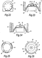
- the fan 11 carries a first clutch part 77 shown in Figure 25 .
- This clutch part 77 includes three arcuate arms 78 which, as the fan 11 rotates, move from the full line position shown in Figure 25 outwardly to the dotted line position shown in that Figure.
- the shutter 69 includes a second clutch part 79 (see Figure 26 ) which includes three outwardly directed equi-angularly spaced projections 80. When the arms 78 are in the full line position shown in Figure 25 , they engage these projections 80 so locking the first and second clutch parts 77,79 together and thus rotating the shutter 69 with the fan 11.
- the arms 78 move to the dotted line position shown in Figure 25 where they are disengaged from the projections 80 so allowing the fan 11 to rotate independently of the shutter 69 with the shutter 69 being maintained in position by air flow (and possibly friction).
- the third fragrance disperser has parts common with the second fragrance disperser of Figures 10 to 14 . Those common parts will be given the same reference numerals and their construction and operation will not be described in detail.
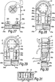
- the third fragrance disperser includes two fragrance sources 81a,81b in which the wick is surrounded by an outlet formed by part of the source.
- each fragrance source 81a,81b includes a container 82a,82b holding a liquid fragrance and including an integral outlet 83a,83b.
- Each outlet 83a,83b is formed at its end remote from the container 82a,82b with an entrance 84a,84b and, at a point in the outlet 83a,83b adjacent the associated container 82a,82b, each outlet 83a,83b is formed with an exit 85a,85b (see Figure 30 ). As seen in Figures 27 and 30 , these exits 85a,85b are aligned with respective apertures 86a,86b in the cover 15 of the housing 10.
- Each outlet 83a,83b contains an upper portion of an elongate strip shaped wick 87a,87b whose lower end is immersed in the fragrance in the container 82a,82b.
- Each outlet is a snap fit in an associated shaped duct 60a,60b of the housing 10.
- rotation of the fan 11 in a clockwise direction produces an air flow which is forced through the first duct 60a and enters the entrance 84a of the outlet 83a of the associated fragrance source 81a.
- the air then passes over and around the wick 87a releasing fragrance which then passes through the exit 85a and through the aperture 86a of the cover 15 to the surrounding atmosphere.
- Anti-clockwise rotation of the fan 11 produces, as seen in Figure 25 , a flow of air through the entrance 84b of the outlet 83b, past the associated wick 87b and then through the exit 85b and the cover aperture 86b.
- the cover apertures 86a,86b may be provided with respective shutter assemblies as described above with reference to Figures 16 and 17 .
- fragrance source 81a,81b When a fragrance source 81a,81b is empty, it can be replaced by a fresh fragrance source.
- the wick 87a,87b is packaged within and protected by the outlet 83a,83b.
- the air duct is part of the fragrance source 81a,81b and is thus a consumable.
- Each wick 87a, 87b may be provided with a wick cover assembly similar to those described above with reference to Figures 18 and 19 , but adapted for consumable fragrance sources.
- the fragrance source is formed by a container 88 comprising a reservoir 89 and an outlet 90.
- the parts may be formed from any suitable material such as a plastics material or glass.
- the outlet 90 is formed at its end remote from the reservoir 89 with an entrance 91 and, at a point in the outlet 90 adjacent the reservoir 89, the outlet 90 is formed with an exit 92.
- a wick 93 leads from the reservoir 89 and terminates in the outlet 90 adjacent the entrance 91.
- the reservoir 89 contains a fragrance.
- a shaped cap 94 covers the outlet 90.
- This container 88 can be used with the fragrance disperser of Figures 27 to 31 .
- the cap 94 is removed and the outlet 90 inserted into the housing 10. Air is then passed through the outlet 90 via the entrance 91 as described above. The air then leaves via the exit 92.
- fragrance sources 81a,81b when mounted on the housing 10, the fragrance sources 81a,81b are side-by-side. It will be appreciated that these two fragrance sources 81a,81b, may contain different fragrances. Not all pairs of fragrances are perceived by the nose as being complementary and it is plainly desirable to avoid combinations that are perceived as non-complementary.
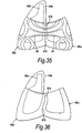
- a first container 88a is provided with a surface pattern 95 that forms a continuous pattern with a corresponding pattern 96 on the second container 88b, with the pattern being continuous across the junction between adjacent side surfaces 97a,97b of the containers 88a,88b.
- These containers 88a,88b are arranged to contain complementary fragrances (i.e. fragrances that are complementary in an olfactory sense) and any container containing a non-complementary fragrance has a different pattern which does not match the pattern of either of the containers in Figure 30 .
- one side surface 97a of one container 88a has a non-planar shape which is complementary with a non-planar shape of the side surface 97b of the other container 88b containing a complementary fragrance so that the side surfaces 97a,97b interlock when the containers 88a,88b are placed side-by-side in the housing 10.
- Containers holding non-complementary fragrances are provided with different side surface configurations and so will not be able to interlock and will thus not be able to be used.
- a fourth form of fragrance disperser is formed by a housing 98 including a chamber having an inner wall 99 formed as a spiral of increasing radius and leading to an outlet 100 extending tangentially from the wall 99.
- a fan 101 is mounted in the housing 98 and is driven by a motor (not shown).
- the outlet contains a fragrance source 102 which may be formed by a half of the fragrance source described above with reference to Figures 5 and 6 .
- the window 41a lies within the outlet 100 and rotation of the fan passes air across the window 41a to evaporate the fragrance.
- the fan 101 rotates in one direction only and so can be designed to be of high efficiency.
- the motor is controlled by a manually operated switch to give fragrance on demand.
- the motor is powered by a source of electric power of the kind described above with reference to Figures 5 and 6 .
- FIG. 38 A variation of this embodiment is shown in Figure 38 . Parts common to Figure 37 and to Figure 38 are given the same reference numerals and are not described in detail.
- the fragrance source is identical to the fragrance source of Figures 5 and 6 with both windows 41a,41b being within the outlet 100.
- the two fragrances in the fragrance source are chosen to combine at the point of dispersion to give a desired single fragrance. This arrangement is particularly useful where the desired fragrance is formed of components that degrade if kept together. By combining them only at the point of dispersion, this degradation is avoided.
- the fragrance source of Figures 8 and 9 could also be used with either of these embodiments.
- the size of the window 41a, 41b may be controlled by an arrangement similar to that described above with reference to Figures 16 and 17 .
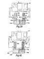
- a fifth form of fragrance disperser includes two sources of fragrance 103a,103b.
- Each source 103a,103b includes a container 104a,104b and an associated wick 105a, 105b projecting from the associated container 104a,104b.
- Each wick 105a,105b is surrounded by an associated heater 106a,106b.
- Each heater 106a,106b is connected to a control board 107 which in turn is connected to an external power supply (not shown). The control board passes current to the heaters 106a,106b in accordance with a predetermined programme.
- control board may be arranged to provide a cycle of evaporation similar to that shown in Figure 7 .
- controls may be provided for different timing protocols as described above with reference to Figure 15 .
- varying the power supply varies the temperature of the heater and thus the volume of fragrance evaporated.
- FIG. 40 An alternative arrangement is shown in Figure 40 . Parts common to Figures 39 and 40 are given the same reference numerals and are not described in detail.
- the heaters 106a,106b are omitted and the wicks 108a,108b are formed of or include an electrically conductive material which is connected to the control board 107. Accordingly, when electrical current is supplied to either wick 108a,108b, the temperature of the wick is raised to evaporate fragrance.
- any of the fragrance dispersers described above with reference to Figures 1 to 4 or 10 to 19 or 27 to 31 may be mounted on a wall.
- the cover 15 is continuous with the air inlet 26 omitted.
- an air inlet 114 is provided on the back wall 13.
- an electrical connector 115 projects from the back wall 13 and includes pins, one of which is shown at 116 received in an electrical socket on a vertical surface 117 such as a wall to support the fragrance disperser and provide electrical power.
- the location of the air inlet 114 is a safety feature since it prevents, for example, fingers being inserted into the path of the fan 11.
Landscapes
- Health & Medical Sciences (AREA)
- Epidemiology (AREA)
- Life Sciences & Earth Sciences (AREA)
- Animal Behavior & Ethology (AREA)
- General Health & Medical Sciences (AREA)
- Public Health (AREA)
- Veterinary Medicine (AREA)
- Disinfection, Sterilisation Or Deodorisation Of Air (AREA)
- Packaging Of Annular Or Rod-Shaped Articles, Wearing Apparel, Cassettes, Or The Like (AREA)
- Structures Of Non-Positive Displacement Pumps (AREA)
Applications Claiming Priority (2)
| Application Number | Priority Date | Filing Date | Title |
|---|---|---|---|
| GBGB0123851.8A GB0123851D0 (en) | 2001-10-04 | 2001-10-04 | Dispersing fragrances |
| EP02770068A EP1432456B1 (de) | 2001-10-04 | 2002-10-04 | Duftspender |
Related Parent Applications (2)
| Application Number | Title | Priority Date | Filing Date |
|---|---|---|---|
| EP02770068.1 Division | 2002-10-04 | ||
| EP02770068A Division EP1432456B1 (de) | 2001-10-04 | 2002-10-04 | Duftspender |
Publications (2)
| Publication Number | Publication Date |
|---|---|
| EP2455108A1 true EP2455108A1 (de) | 2012-05-23 |
| EP2455108B1 EP2455108B1 (de) | 2017-08-23 |
Family
ID=9923242
Family Applications (3)
| Application Number | Title | Priority Date | Filing Date |
|---|---|---|---|
| EP11010181.3A Expired - Lifetime EP2455107B1 (de) | 2001-10-04 | 2002-10-04 | Duftspender |
| EP02770068A Expired - Lifetime EP1432456B1 (de) | 2001-10-04 | 2002-10-04 | Duftspender |
| EP11010182.1A Expired - Lifetime EP2455108B1 (de) | 2001-10-04 | 2002-10-04 | Duftspender |
Family Applications Before (2)
| Application Number | Title | Priority Date | Filing Date |
|---|---|---|---|
| EP11010181.3A Expired - Lifetime EP2455107B1 (de) | 2001-10-04 | 2002-10-04 | Duftspender |
| EP02770068A Expired - Lifetime EP1432456B1 (de) | 2001-10-04 | 2002-10-04 | Duftspender |
Country Status (6)
| Country | Link |
|---|---|
| US (8) | US7344123B2 (de) |
| EP (3) | EP2455107B1 (de) |
| JP (4) | JP4638147B2 (de) |
| ES (3) | ES2645789T3 (de) |
| GB (1) | GB0123851D0 (de) |
| WO (1) | WO2003028775A1 (de) |
Families Citing this family (147)
| Publication number | Priority date | Publication date | Assignee | Title |
|---|---|---|---|---|
| US20040028551A1 (en) * | 2000-07-27 | 2004-02-12 | Kvietok Frank Andrej | Methods for emitting volatile compositions |
| US20040033171A1 (en) | 2000-07-27 | 2004-02-19 | The Procter & Gamble Company | Systems and devices for emitting volatile compositions |
| US8061628B1 (en) | 2000-07-27 | 2011-11-22 | The Procter & Gamble Company | Systems and devices for emitting volatile compositions |
| GB0123851D0 (en) * | 2001-10-04 | 2001-11-28 | Pankhurst Design & Development | Dispersing fragrances |
| US7469844B2 (en) * | 2002-11-08 | 2008-12-30 | S.C. Johnson & Son, Inc. | Diffusion device and method of diffusing |
| ATE352324T1 (de) * | 2002-11-12 | 2007-02-15 | Givaudan Sa | Elektrisch betriebene vorrichtung zur abgabe von verdampfbaren stoffen |
| US8460609B1 (en) | 2003-02-28 | 2013-06-11 | American Covers, Inc. | Vent stick air freshener with grip head |
| US7540473B2 (en) | 2003-03-21 | 2009-06-02 | S.C. Johnson & Son, Inc. | Dispensing system for a volatile liquid |
| GB2401047B (en) * | 2003-04-28 | 2006-03-15 | Carbonate Ltd | Fragrance dispersers |
| GB0410194D0 (en) * | 2004-05-07 | 2004-06-09 | Givaudan Sa | Apparatus |
| EP1595552B1 (de) * | 2004-05-10 | 2008-06-25 | Sara Lee/DE N.V. | Lufterfrischungsgerät für Autos |
| US7389943B2 (en) * | 2004-06-30 | 2008-06-24 | S.C. Johnson & Son, Inc. | Electromechanical apparatus for dispensing volatile substances with single dispensing mechanism and cartridge for holding multiple receptacles |
| US7426799B2 (en) * | 2004-06-30 | 2008-09-23 | S.C. Johnson & Son, Inc. | Air freshener with frame and refill holder |
| US7607250B2 (en) * | 2004-06-30 | 2009-10-27 | S.C. Johnson & Son, Inc. | Air freshener with picture frame |
| US7441360B2 (en) | 2004-06-30 | 2008-10-28 | S.C. Johnson & Son, Inc. | Air freshener with picture frame |
| US20060002102A1 (en) * | 2004-06-30 | 2006-01-05 | Leonard Stephen B | Volatile material dispensing system with illuminating device |
| US7382975B2 (en) * | 2004-09-14 | 2008-06-03 | Zobele Espana, S.A. | Evaporator device for active substances with fan |
| KR20110116183A (ko) | 2004-10-12 | 2011-10-25 | 에스.씨. 존슨 앤드 선, 인코포레이티드 | 소형의 스프레이 기구 |
| US8061562B2 (en) | 2004-10-12 | 2011-11-22 | S.C. Johnson & Son, Inc. | Compact spray device |
| WO2006084921A1 (es) | 2005-02-03 | 2006-08-17 | Zobele España, S.A. | Difusor de sustancias volátiles multifragancia |
| GB2423930A (en) * | 2005-03-11 | 2006-09-13 | Reckitt Benckiser | Emanation or fragrancing device |
| US7589340B2 (en) * | 2005-03-31 | 2009-09-15 | S.C. Johnson & Son, Inc. | System for detecting a container or contents of the container |
| KR20080009685A (ko) * | 2005-04-12 | 2008-01-29 | 에스.씨. 존슨 앤드 선, 인코포레이티드 | 확산기구 및 확산방법 |
| US7622073B2 (en) * | 2005-04-12 | 2009-11-24 | S.C. Johnson & Son, Inc. | Apparatus for and method of dispensing active materials |
| US20060231641A1 (en) * | 2005-04-14 | 2006-10-19 | Hirotaka Uchiyama | Devices with anti-leak features for delivering volatile materials |
| US20060233538A1 (en) * | 2005-04-14 | 2006-10-19 | Tollens Fernando R | Energized systems and devices for delivering volatile materials |
| US20070025888A1 (en) * | 2005-08-01 | 2007-02-01 | Gupte Anil J | Diffuser |
| US8685330B2 (en) | 2005-10-31 | 2014-04-01 | American Covers, Inc. | Air freshener flower with vent stick |
| GB2432789B (en) * | 2005-12-01 | 2011-08-10 | Sara Lee De Nv | Fragrance delivery system |
| US7841586B1 (en) * | 2005-12-23 | 2010-11-30 | Humid-EZE, Inc. | Humidification apparatus and method of manufacture and use |
| US7665238B2 (en) * | 2006-04-03 | 2010-02-23 | S.C. Johnson & Son, Inc. | Air freshener with holder |
| US7523577B2 (en) * | 2006-04-03 | 2009-04-28 | S.C. Johnson & Son, Inc. | Air freshener with holder |
| US7493028B2 (en) | 2006-04-04 | 2009-02-17 | Group Dekko, Inc. | Multiple bottle evaporative diffuser |
| US7651666B2 (en) * | 2006-04-20 | 2010-01-26 | S.C. Johnson & Son, Inc. | Air treatment device with reservoir refill |
| US20070257383A1 (en) * | 2006-05-05 | 2007-11-08 | Kelvin Chan | Wearable Self-Contained Personal Humidifier |
| GB0608919D0 (en) * | 2006-05-08 | 2006-06-14 | Givaudan Sa | Device |
| US7734159B2 (en) * | 2006-08-31 | 2010-06-08 | S.C. Johnson & Son, Inc. | Dispersion device for dispersing multiple volatile materials |
| EP1902736A1 (de) * | 2006-09-19 | 2008-03-26 | Sara Lee/DE N.V. | Lufterfrischer zum Verströmen zweier Düfte |
| DE102006061825A1 (de) * | 2006-12-21 | 2008-06-26 | Behr Gmbh & Co. Kg | Beduftungssystem, insbesondere für ein Kraftfahrzeug |
| DE102008011174B4 (de) * | 2007-02-26 | 2020-06-04 | Mahle International Gmbh | Bedufungsvorrichtung, insbesondere für ein Kraftfahrzeug |
| US20080232964A1 (en) * | 2007-03-19 | 2008-09-25 | Lawrence Edward Thomasson | Daisy fan |
| US20120315161A1 (en) * | 2007-03-19 | 2012-12-13 | Lawrence Edward Thomasson | Portable mechanical fan |
| FR2918316B1 (fr) * | 2007-07-02 | 2014-06-27 | Valeo Systemes Thermiques | Dispositif de diffusion d'agent volatil muni d'un pulseur pour vehicule automobile |
| FR2919504B1 (fr) | 2007-08-01 | 2010-01-01 | Marcel Jean | Dispositif de parfumage d'ambiance permettant de choisir entre au moins deux fragrances differentes, ou de les melanger pour en obtenir une nouvelle |
| DE102007045160A1 (de) * | 2007-09-20 | 2009-04-02 | Behr Gmbh & Co. Kg | Beduftungssystem, insbesondere für ein Kraftfahrzeug |
| AU2008330105A1 (en) | 2007-11-26 | 2009-06-04 | S.C. Johnson & Son, Inc. | Volatile material dispensing system |
| US8320751B2 (en) * | 2007-12-20 | 2012-11-27 | S.C. Johnson & Son, Inc. | Volatile material diffuser and method of preventing undesirable mixing of volatile materials |
| USD584809S1 (en) | 2008-02-04 | 2009-01-13 | S. C. Johnson & Son, Inc. | Dispensing device |
| JP5121060B2 (ja) * | 2008-05-28 | 2013-01-16 | フマキラー株式会社 | 送風式薬剤放散装置 |
| JP5121061B2 (ja) * | 2008-06-17 | 2013-01-16 | フマキラー株式会社 | 送風式薬剤放散装置 |
| US20100044468A1 (en) * | 2008-06-26 | 2010-02-25 | Momentum Industries, Llc | Device for distributing volatile fluids in air |
| DE102008032612A1 (de) * | 2008-07-11 | 2010-01-14 | Behr Gmbh & Co. Kg | Duftmittelvorratsvorrichtung |
| DE102008032615A1 (de) * | 2008-07-11 | 2010-01-14 | Behr Gmbh & Co. Kg | Duftmittelvorratsvorrichtung |
| US20100065659A1 (en) * | 2008-09-16 | 2010-03-18 | Bill Nguyen | Air pop dancing light air freshener |
| US8293172B2 (en) * | 2008-09-29 | 2012-10-23 | S.C. Johnson & Son, Inc. | Method of dispensing a volatile material |
| US8197762B2 (en) * | 2008-09-29 | 2012-06-12 | S.C. Johnson & Son, Inc. | Method of dispensing a volatile material |
| WO2010079486A1 (en) * | 2009-01-08 | 2010-07-15 | Scentcom, Ltd. | Method and apparatus for computer controlled scent delivery |
| US9453652B2 (en) | 2009-01-09 | 2016-09-27 | S. C. Johnson & Son, Inc. | Fragrance dispenser |
| USD598531S1 (en) | 2009-01-27 | 2009-08-18 | American Covers, Inc. | Single scent air freshener |
| US8851396B2 (en) * | 2009-01-27 | 2014-10-07 | American Covers, Inc. | Dual scent air freshener with manual combiner |
| USD607983S1 (en) | 2009-01-27 | 2010-01-12 | American Covers, Inc. | Dual scent air freshener with manual combiner |
| EP2429844B1 (de) * | 2009-05-12 | 2020-03-25 | The Procter and Gamble Company | Spender für flüchtige zusammensetzungen |
| CA2762488C (en) * | 2009-05-21 | 2013-12-10 | S. C. Johnson & Son, Inc. | Methods of dispensing two or more volatile materials |
| US8412030B2 (en) * | 2009-08-26 | 2013-04-02 | S.C. Johnson & Son, Inc. | Method and apparatus for dispensing a fragrance |
| MX2012003412A (es) * | 2009-09-21 | 2012-04-30 | Johnson & Son Inc S C | Metodo para emitir un material volatil desde un difusor. |
| BR112012008596B1 (pt) * | 2009-10-13 | 2019-03-19 | Philip Morris Products S.A. | Dispositivo para renovação de ar e métodos para a geração de material vaporizado e geração pulsante repetida do mesmo |
| US8662409B2 (en) * | 2009-10-26 | 2014-03-04 | S.C. Johnson & Son, Inc. | Multi-layered active ingredient dispenser |
| US8485454B1 (en) | 2009-12-30 | 2013-07-16 | American Covers, Inc. | Rotatable and adjustable air freshener |
| BR112012018894A2 (pt) | 2010-01-29 | 2016-04-12 | Procter & Gamble | copolímeros de polidimetilsiloxano-poliéter lineares como grupos amino e/ou amônio quaternário e uso dos mesmos |
| DE102010001350A1 (de) | 2010-01-29 | 2011-08-04 | Evonik Goldschmidt GmbH, 45127 | Neuartige lineare Polydimethylsiloxan-Polyether-Copolymere mit Amino- und/oder quaternären Ammoniumgruppen und deren Verwendung |
| WO2011119557A2 (en) * | 2010-03-26 | 2011-09-29 | The Procter & Gamble Company | Kit and method for removing hair |
| USD639923S1 (en) | 2010-04-15 | 2011-06-14 | S.C. Johnson & Son, Inc. | Dispensing device |
| US9770524B2 (en) | 2010-07-16 | 2017-09-26 | S. C. Johnson & Son, Inc. | Volatile material dispenser and method of attaching a refill or refills to same |
| US9962516B2 (en) | 2010-09-09 | 2018-05-08 | University Of Florida Research Foundation, Incorporated | Context-sensitive flow interrupter and drainage outflow optimization system |
| GB201015168D0 (en) * | 2010-09-10 | 2010-10-27 | Slade Brian P | Volatile material dispenser, and dispensing screen thereof |
| US9717814B2 (en) | 2010-10-01 | 2017-08-01 | S. C. Johnson & Son, Inc. | Dispensing device |
| USD660950S1 (en) | 2010-10-29 | 2012-05-29 | American Covers, Inc. | Air freshener diffuser with air tunnel |
| US8673223B1 (en) | 2010-10-29 | 2014-03-18 | American Covers, Inc. | Fan powered air freshener automobile visor clip |
| USD640359S1 (en) | 2010-10-29 | 2011-06-21 | American Covers, Inc. | Vent stick air freshener with grip head |
| US8251299B1 (en) | 2010-10-29 | 2012-08-28 | American Covers, Inc. | Screw top air freshener |
| USD640358S1 (en) | 2010-10-29 | 2011-06-21 | American Covers, Inc. | Screw top air freshener |
| US8662480B1 (en) | 2010-10-29 | 2014-03-04 | American Covers, Inc. | Fan powered air freshener automobile power outlet |
| USD662580S1 (en) * | 2010-12-14 | 2012-06-26 | Conopco Inc. | Spray dispenser refill |
| US8490846B1 (en) | 2011-01-10 | 2013-07-23 | American Covers, Inc. | Frictional holding pad with inclined grip |
| EP2667902A2 (de) | 2011-01-26 | 2013-12-04 | Scentcom Ltd. | Duftstofferzeugende vorrichtung |
| US8517351B2 (en) | 2011-04-28 | 2013-08-27 | S.C. Johnson & Son, Inc. | Centrifugal fan device |
| US8807538B2 (en) | 2011-04-28 | 2014-08-19 | S.C. Johnson & Son, Inc. | Centrifugal fan device |
| USD659818S1 (en) | 2011-04-28 | 2012-05-15 | S.C. Johnson & Son, Inc. | Dispenser |
| US8939435B2 (en) | 2011-06-03 | 2015-01-27 | Microlin, Llc | Device for delivery of volatile liquids to gaseous environment utilizing a gas generating cell |
| CA143436S (en) * | 2011-06-20 | 2012-06-21 | Reckitt & Colman Overseas | Refill for an air freshener device |
| USD688364S1 (en) * | 2011-07-19 | 2013-08-20 | Frederick A. Gammon | Air freshener device |
| USD661790S1 (en) | 2011-07-25 | 2012-06-12 | Majerowski Amelia H | Cover for a dispenser |
| US8881945B2 (en) | 2011-09-19 | 2014-11-11 | S.C. Johnson & Son, Inc. | Spray dispenser |
| US9155811B1 (en) | 2011-12-02 | 2015-10-13 | American Covers, Inc. | Packaged vent stick air freshener with custom head |
| US9144621B1 (en) | 2012-01-10 | 2015-09-29 | American Covers, Inc. | Air freshener canister with pull top |
| USD676949S1 (en) * | 2012-01-17 | 2013-02-26 | Star Brite Distributing, Inc. | Disinfectant distributor |
| US8622246B2 (en) | 2012-02-13 | 2014-01-07 | Ecolab Usa Inc. | Fluid reservoir docking station |
| US20130320574A1 (en) * | 2012-05-18 | 2013-12-05 | The Yankee Candle Company, Inc. | Aerodynamic formula dispersing apparatus |
| US8807540B2 (en) | 2012-06-12 | 2014-08-19 | S.C. Johnson & Son, Inc. | Fan-based volatile material dispensing system |
| USD706140S1 (en) | 2012-06-25 | 2014-06-03 | Mary Kay Inc. | Bottles |
| EP2890410B1 (de) | 2012-08-28 | 2017-05-17 | S.C. Johnson & Son, Inc. | Verfahren zur alternativen emission zweier oder mehrerer flüchtiger materialien |
| USD691254S1 (en) * | 2012-09-05 | 2013-10-08 | Reckitt & Colman (Overseas) Limited | Air freshener refill |
| US9108782B2 (en) | 2012-10-15 | 2015-08-18 | S.C. Johnson & Son, Inc. | Dispensing systems with improved sensing capabilities |
| US9205165B2 (en) | 2012-10-22 | 2015-12-08 | S.C. Johnson & Son, Inc. | Volatile material dispensing system having an adjustable diffusion apparatus |
| US9138502B2 (en) | 2012-10-23 | 2015-09-22 | American Covers, Inc. | Air freshener with decorative insert |
| US9042712B2 (en) | 2012-10-23 | 2015-05-26 | American Covers, Inc. | Heated air freshener for 12V receptacle |
| USD689181S1 (en) | 2012-10-23 | 2013-09-03 | American Covers, Inc. | Air freshener container |
| US9399080B2 (en) | 2012-10-23 | 2016-07-26 | American Covers, Inc. | Heated air freshener with power port for 12v receptacle |
| USD684675S1 (en) | 2012-10-23 | 2013-06-18 | American Covers, Inc. | Dual axis vent rod air freshener |
| US9726395B2 (en) | 2012-11-20 | 2017-08-08 | Scott David Hammer | Air freshening system and method |
| US9726199B2 (en) | 2013-03-15 | 2017-08-08 | Scott David Hammer | Air freshening system and method |
| USD711521S1 (en) | 2013-04-15 | 2014-08-19 | American Covers, Inc. | Skull on dog tag shaped air freshener |
| USD727749S1 (en) | 2013-05-02 | 2015-04-28 | Mary Kay Inc. | Bottles |
| USD705413S1 (en) * | 2013-05-06 | 2014-05-20 | Zobele Holdings S.P.A. | Air freshener |
| USD702336S1 (en) * | 2013-05-06 | 2014-04-08 | Zobele Holding Spa | Air freshener |
| KR102187220B1 (ko) * | 2013-08-09 | 2020-12-04 | 서울바이오시스 주식회사 | 분기가능한 공기 배관을 구비하는 공기 정화 장치 |
| US9149031B2 (en) | 2013-09-13 | 2015-10-06 | S.C. Johnson & Son, Inc. | Portable area repellent device |
| US10378558B2 (en) | 2013-09-13 | 2019-08-13 | S.C. Johnson & Son, Inc. | Air treatment chemical dispenser having angled dispersion of chemicals |
| US9327045B2 (en) * | 2013-10-22 | 2016-05-03 | American Covers, Inc. | Air freshener with porous membrane with leak pad and adjustable opening |
| US9352062B2 (en) | 2013-10-30 | 2016-05-31 | S.C. Johnson & Son, Inc. | Wearable chemical dispenser |
| US10220109B2 (en) | 2014-04-18 | 2019-03-05 | Todd H. Becker | Pest control system and method |
| CN106456820B (zh) | 2014-04-18 | 2018-05-25 | T·A·康罗伊 | 包括液位传感器的扩散器网络的方法和系统 |
| US9352064B2 (en) | 2014-06-05 | 2016-05-31 | S. C. Johnson & Son, Inc. | Wearable chemical dispenser |
| US10940279B2 (en) | 2014-07-01 | 2021-03-09 | Jennifer K. Keener | Aromatherapy device |
| US9925351B2 (en) * | 2014-07-01 | 2018-03-27 | Jennifer K. Keener | Aromatherapy device |
| WO2016019074A1 (en) | 2014-07-30 | 2016-02-04 | Georgia-Pacific Consumer Products Lp | Air freshener dispensers, cartridges therefor, systems, and methods |
| US20160309701A1 (en) * | 2015-03-30 | 2016-10-27 | James DeHaven | Heated Animal Scent Dispenser |
| KR20180041658A (ko) * | 2015-06-10 | 2018-04-24 | 피프스 스크린 디지털 인코퍼레이티드 | 향기 카트리지 및 챔버 확산 시스템 |
| US10345016B2 (en) | 2016-04-04 | 2019-07-09 | B/E Aerospace, Inc. | Air treatment module |
| DE102016211491A1 (de) * | 2016-06-27 | 2017-12-28 | Ford Global Technologies, Llc | Verfahren zum Betreiben eines Heizungs-, Lüftungs- und Klimaanlagen-Systems eines Fahrzeugs |
| CN117860941A (zh) * | 2016-06-30 | 2024-04-12 | 索尼公司 | 香水保持器构件以及香味提供装置 |
| US10675373B2 (en) * | 2016-07-27 | 2020-06-09 | Newmarket Concepts, Llc | Fragrance dispenser having a disposable piezoelectric cartridge with a snap-in bottle containing aromatic liquid |
| CN109789232A (zh) | 2016-08-03 | 2019-05-21 | T·H·贝克利 | 联网气味扩散装置的方法和系统 |
| US11097601B2 (en) * | 2016-08-17 | 2021-08-24 | Merrium Patterson | Scent warmer |
| US10764963B2 (en) | 2016-10-07 | 2020-09-01 | S. C. Johnson & Son, Inc. | Volatile material dispenser |
| WO2018122350A1 (en) * | 2016-12-29 | 2018-07-05 | Airparfum Timeless, S.L. | Perfume testers |
| CN111032096A (zh) * | 2017-09-15 | 2020-04-17 | 索尼公司 | 香料保持结构、制造香料保持结构的方法及香味提供装置 |
| CN111511410B (zh) * | 2018-01-18 | 2022-10-11 | 宝洁公司 | 将挥发性组合物递送到空气中的方法 |
| USD912794S1 (en) | 2018-08-01 | 2021-03-09 | Fresh Products, Inc. | Air freshener |
| USD900291S1 (en) | 2018-08-06 | 2020-10-27 | Fresh Products, Inc. | Air freshener |
| US12036846B2 (en) | 2019-02-08 | 2024-07-16 | Henkel Ag & Co. Kgaa | System for distributing volatile substance with base unit and self-sealing removable capsule |
| CN212098347U (zh) | 2020-02-20 | 2020-12-08 | 上海延锋金桥汽车饰件系统有限公司 | 用于车辆内部的香味分配装置 |
| CN110081544A (zh) * | 2019-05-29 | 2019-08-02 | 深圳市景欣泰家居用品有限公司 | 一种空气加湿器 |
| US12458722B1 (en) | 2020-02-27 | 2025-11-04 | Fresh Products, Inc. | Systems, method, and devices for dispensing volatile liquids |
| CN116615625A (zh) * | 2020-12-16 | 2023-08-18 | 特洛依海伦有限公司 | 蒸发式加湿器 |
| CN114056775B (zh) * | 2021-11-18 | 2023-03-24 | 山东迈得新材料有限公司 | 一种3d打印用钴铬合金粉存放装置 |
| TWI807890B (zh) * | 2022-06-29 | 2023-07-01 | 和碩聯合科技股份有限公司 | 香氛裝置 |
Citations (6)
| Publication number | Priority date | Publication date | Assignee | Title |
|---|---|---|---|---|
| US4998671A (en) * | 1989-10-20 | 1991-03-12 | The Drackett Company | Multiple compartment flexible package |
| DE4131613A1 (de) * | 1991-09-23 | 1993-03-25 | Globol Gmbh | Verdunstungsvorrichtung |
| EP0722742A2 (de) * | 1994-12-23 | 1996-07-24 | Globol GmbH | Behälter zur Aufnahme von Wirkstoffen wie Duftstoffen, Insektiziden oder dergleichen |
| WO1998047772A2 (en) * | 1997-04-24 | 1998-10-29 | Unifill International A/G | Methods and apparatus and units produced by the same |
| US5857620A (en) * | 1997-07-14 | 1999-01-12 | The Scott Fetzer Company | Liquid dispenser with integral wick/emanator assembly |
| US6254065B1 (en) * | 1997-07-11 | 2001-07-03 | Cws International Ag | Evaporation dispenser having a control timer for timed release of a volatile substance from an evaporation chamber |
Family Cites Families (202)
| Publication number | Priority date | Publication date | Assignee | Title |
|---|---|---|---|---|
| US1109567A (en) * | 1913-04-24 | 1914-09-01 | William C Clifford | Humidifier. |
| GB484035A (en) | 1937-05-07 | 1938-04-29 | Blyth & Platt Ltd | Improvements in or relating to holders for volatile disinfectants and like substances |
| US2878061A (en) * | 1957-10-22 | 1959-03-17 | Puro Co Inc | Moth preventive and deodorant dispensers |
| US3613994A (en) | 1969-06-23 | 1971-10-19 | Richard E Goodman | Vapor-dispensing device |
| DE2351979C2 (de) * | 1973-10-17 | 1985-03-21 | Fa. J. Eberspächer, 7300 Esslingen | Reaktor für die Nachverbrennung von brennbaren Bestandteilen in Abgasen von Brennkraftmaschinen |
| FR2328087A1 (fr) | 1975-10-16 | 1977-05-13 | Tournade Francois | Appareil pour le traitement en continu des colonnes de vide-ordures, des gaines d'aeration et des descentes de linge |
| US4067692A (en) | 1976-06-10 | 1978-01-10 | Farris Richard W | Odor control device |
| JPS53158551U (de) * | 1977-05-16 | 1978-12-12 | ||
| FR2409928A1 (fr) * | 1977-11-28 | 1979-06-22 | Paco Rabanne Parfums Sa | Dispositif de conditionnement de liquide tel que parfum |
| NZ191657A (en) * | 1978-10-18 | 1983-09-30 | Georgia Pacific Corp | Air freshener dispenser |
| US4294778A (en) | 1978-10-18 | 1981-10-13 | Georgia-Pacific Corporation | Evaporative dispenser |
| US4396557A (en) * | 1979-08-13 | 1983-08-02 | Georgia-Pacific Corporation | Evaporative dispenser |
| JPS5742438Y2 (de) | 1980-07-11 | 1982-09-18 | ||
| US4301095A (en) | 1980-08-18 | 1981-11-17 | Product Enterprise, Inc. | Air freshener dispenser |
| CA1160318A (en) * | 1981-01-23 | 1984-01-10 | Yasuyuki Mori | Aromatic odorant emitting device |
| US4695434A (en) | 1982-08-27 | 1987-09-22 | Donald Spector | Aroma-generating unit |
| US4629604A (en) | 1983-03-21 | 1986-12-16 | Donald Spector | Multi-aroma cartridge player |
| US4603030A (en) * | 1984-09-20 | 1986-07-29 | Mccarthy Robert E | Scent-Emitting Systems |
| DE3765149D1 (de) | 1986-03-27 | 1990-10-31 | Firmenich & Cie | Automatische vorrichtung zur zerstreuung von desinfizierenden daempfen. |
| JPH0686362B2 (ja) * | 1986-05-29 | 1994-11-02 | フマキラ−株式会社 | 薬剤の加熱蒸散方法 |
| EG18025A (en) | 1986-07-18 | 1993-06-30 | Sumitomo Chemical Co | A method for killing insects by heating fumigation |
| AU594495B2 (en) | 1986-09-02 | 1990-03-08 | Fumakilla Limited | Heat fumigation apparatus |
| JPS63100048U (de) * | 1986-12-17 | 1988-06-29 | ||
| US4840770A (en) * | 1987-02-24 | 1989-06-20 | Seco Industries, Inc. | Odor control product dispenser |
| CA1318285C (en) * | 1987-06-10 | 1993-05-25 | Hiroji Machida | Method for supplying aromas, apparatus therefore and facilities provided with same |
| FR2617384B1 (fr) * | 1987-06-30 | 1989-12-08 | Lux Colette Solange | Article destine a contenir un echantillon d'une substance odorante |
| US4798935A (en) | 1987-07-08 | 1989-01-17 | Environmental Fragrance Technologies, Ltd. | Driver circuit |
| JPH01186423A (ja) | 1988-01-20 | 1989-07-25 | Shimizu Corp | 車室への香り供給方法 |
| JPH0718294Y2 (ja) | 1988-02-10 | 1995-05-01 | アース製薬株式会社 | 加熱蒸散器 |
| ES1004915Y (es) | 1988-03-04 | 1989-04-01 | Cooper-Zeltia, S.A. | Dispositivo para vaporizar sustancias termicamente vaporizables. |
| JPH01140956U (de) * | 1988-03-22 | 1989-09-27 | ||
| JPH01176439U (de) * | 1988-05-30 | 1989-12-15 | ||
| US4905112A (en) | 1988-06-24 | 1990-02-27 | Rhodes Steven W | Scent cassette |
| JPH02126855A (ja) | 1988-11-07 | 1990-05-15 | Nippon Chem Kogyo Kk | 芳香器 |
| JPH02209147A (ja) | 1989-02-07 | 1990-08-20 | Shimizu Corp | 超音波式香り発生装置 |
| JPH0511867Y2 (de) * | 1989-03-28 | 1993-03-25 | ||
| US4959087A (en) | 1989-06-14 | 1990-09-25 | James Kappernaros | Air conditioning system filter with variable rate scent release |
| US5234162A (en) | 1989-09-13 | 1993-08-10 | Ecolab Inc. | Air freshener device cartridge |
| US5342584A (en) | 1989-09-13 | 1994-08-30 | Ecolab Inc. | Air freshener device and cartridge with battery |
| US5050798A (en) | 1989-09-13 | 1991-09-24 | Ecolab Inc. | Static air freshener device and cartridge |
| US5038972A (en) | 1989-09-26 | 1991-08-13 | Technical Concepts, Inc. | Metered aerosol fragrance dispensing mechanism |
| IT1231085B (it) | 1989-09-29 | 1991-11-12 | Zobele Ind Chim | Apparecchio per tenere lontano dalle persone insetti volatili, in particolare zanzare e procedimento di fabbricazione. |
| US5381916A (en) * | 1990-03-28 | 1995-01-17 | Strawder; Glenn G. | Modular receptacles |
| DE4033926A1 (de) | 1990-03-29 | 1991-10-02 | Peter Wohland | Vorrichtung zur abgabe von fluechtigen stoffen an die umgebungsluft |
| US5259062A (en) * | 1990-04-24 | 1993-11-02 | Pelko Electric Corporation | Air treatment apparatus utilizing interchangeable cartridges |
| US5175791A (en) | 1990-05-07 | 1992-12-29 | Technical Concepts, L.P. | Fragrance diffuser having stepped power levels |
| US5115975A (en) | 1990-07-24 | 1992-05-26 | Lynndon Shilling | Dispenser device and cartridge for volatile substance with rate control for volatilization thereof |
| GB2247623A (en) | 1990-09-05 | 1992-03-11 | Secto Co Ltd | Volatile liquid dispenser powered by rechargeable battery and solar cell charge |
| US5105133A (en) | 1990-09-14 | 1992-04-14 | Yang Tai Her | Multiple mode perfumer |
| FR2670568B1 (fr) | 1990-12-18 | 1993-05-28 | Parant Jean Pierre | Dispositif pour le traitement de l'air de locaux. |
| NL9100089A (nl) | 1991-01-17 | 1992-08-17 | Sara Lee De Nv | Verdamper met gecombineerde continu- en instantactieve werking. |
| US5158191A (en) | 1991-03-01 | 1992-10-27 | Plastic Processing Corporation | Dual bottle container having a dual outlet cap |
| JP2577904Y2 (ja) * | 1991-03-07 | 1998-08-06 | エステー化学株式会社 | 複合容器 |
| US5178327A (en) | 1991-08-02 | 1993-01-12 | Summit Products, Inc. | Air freshener |
| EP0538527A1 (de) | 1991-10-25 | 1993-04-28 | Sano - Bruno's Enterprises Ltd. | Elektrischer Verdampfer mit zweifacher Funktion für Tabletten |
| DE4135796A1 (de) | 1991-10-30 | 1993-05-06 | Goetz-Ulrich London Gb Wittek | Verfahren und vorrichtung fuer die ereignisbezogene oder szenengenaue duftdarbietung bei cinematographischen auffuehrungen und dergleichen |
| US5212672A (en) | 1991-11-20 | 1993-05-18 | Loisch Julius A | Timing control apparatus |
| JPH05146498A (ja) * | 1991-11-27 | 1993-06-15 | Hayase & Co:Kk | 消臭装置及び消臭方法 |
| US5222186A (en) | 1991-12-06 | 1993-06-22 | Globol Gmbh | Electrical apparatus for vaporizing of active substances |
| US5167877A (en) * | 1991-12-10 | 1992-12-01 | Pai Wen Chung | Air purifier with perfume dispensing control |
| JPH0719169B2 (ja) * | 1992-04-17 | 1995-03-06 | 株式会社豊田中央研究所 | 発香器のゆらぎ駆動装置 |
| US5314669A (en) | 1992-06-15 | 1994-05-24 | Randy Hamilton | Method and apparatus for dispensing a scent into the air |
| US5242111A (en) | 1992-08-13 | 1993-09-07 | John Nakoneczny | Wick type liquid dispensing device for the slow controlled dispensing and diffusion of liquids over an extended period of time |
| FR2695305B3 (fr) | 1992-09-07 | 1995-01-13 | France Assessoires Automobiles | Diffuseur de parfum pour véhicule. |
| EP0664919B1 (de) | 1992-10-16 | 1997-05-14 | TEBBE, Gerold | Aufzeichnungsträger und gerät zum erzeugen von tönen und/oder bildern |
| US5324490A (en) * | 1992-11-02 | 1994-06-28 | Eftichios Van Vlahakis | Deodorant container and perfumed stable gel assembly and method of manufacture |
| US5521357A (en) | 1992-11-17 | 1996-05-28 | Heaters Engineering, Inc. | Heating device for a volatile material with resistive film formed on a substrate and overmolded body |
| JPH06207304A (ja) | 1993-01-12 | 1994-07-26 | Sekisui Chem Co Ltd | アートフラワー形香り発生装置 |
| CN2166101Y (zh) | 1993-04-20 | 1994-05-25 | 卜冠华 | 香料溶剂气体产生装置 |
| US5439100A (en) * | 1993-05-04 | 1995-08-08 | The Dial Corp. | Packaging system for dispensing cartridge for volatiles |
| GB2279010A (en) | 1993-06-18 | 1994-12-21 | Kuan Hua Pu | A Device for selectively generating perfume gas |
| US5434386A (en) | 1993-09-01 | 1995-07-18 | Holmes Products Corp. | Electric circuit having a heater element and a night light |
| US5321669A (en) | 1993-09-03 | 1994-06-14 | Richard Thayer | Aromatic alarm clock system |
| US5449117A (en) | 1993-10-04 | 1995-09-12 | Technical Concepts, L.P. | Apparatus and method for controllably dispensing drops of liquid |
| US5370829A (en) * | 1993-10-15 | 1994-12-06 | Waterbury Companies, Inc. | Apparatus for inducing air flow past a cartridge containing a vaporizable substance |
| JP3526599B2 (ja) * | 1993-12-24 | 2004-05-17 | エステー化学株式会社 | 感熱性揮散調節構造体 |
| US5727186A (en) | 1994-02-01 | 1998-03-10 | The Boc Group Plc | Simulation apparatus and gas dispensing device used in conjunction therewith |
| FR2717392B1 (fr) * | 1994-03-16 | 1996-06-07 | Prodifa Sarl | Diffuseur dynamique d'une substance telle qu'un parfum. |
| JPH07289624A (ja) * | 1994-04-21 | 1995-11-07 | Haatec:Kk | コーヒー香り発生器 |
| US6141496A (en) | 1994-06-06 | 2000-10-31 | The Erie Ceramic Arts Company | Electrically heated air fresheners |
| IT234344Y1 (it) | 1994-06-28 | 2000-03-09 | Falp Srl | Apparecchio per la vaporizzazione di soluzioni insetticide o simili |
| US6234455B1 (en) * | 1994-06-30 | 2001-05-22 | Gotz-Ulrich Wittek | Device and process for delivering substances for dispersal in the air |
| DE4430291C2 (de) | 1994-08-26 | 1996-07-25 | Steinel Gmbh & Co Kg | Vorrichtung zum Verdunsten eines flüssigen Wirkstoffs |
| DE4433954C2 (de) | 1994-09-23 | 1996-07-11 | Bayer Ag | Langzeitverdampfer mit Docht |
| JPH08155021A (ja) * | 1994-12-06 | 1996-06-18 | Japan Energy Corp | 香料発散器 |
| GB9501065D0 (en) | 1995-01-18 | 1995-03-08 | Kennedy Eng Holding David | Air freshener unit and cartridge therefor and method of dispensing air freshening vapour |
| US5577630A (en) * | 1995-02-02 | 1996-11-26 | Thiokol Corporation | Composite conformable pressure vessel |
| US5565148A (en) | 1995-03-16 | 1996-10-15 | Minnesota Mining And Manufacturing Company | Device for selectively providing a multiplicity of aromas |
| DE29504734U1 (de) | 1995-03-20 | 1996-07-18 | Perycut-Chemie AG, Zürich | Verdampfervorrichtung |
| US5772074A (en) | 1995-03-31 | 1998-06-30 | Waterbury Companies, Inc. | Device and method for indicating the dispensing of a predetermined amount of a material |
| IT1280407B1 (it) | 1995-04-06 | 1998-01-20 | Falp Srl | Apparecchio per la vaporizzazione di soluzioni insetticide o simili |
| US5898475A (en) | 1995-06-19 | 1999-04-27 | Martin; David A. | Precision fragrance dispenser apparatus |
| US5591409A (en) | 1995-08-15 | 1997-01-07 | Watkins; Carl J. | Providing aromas |
| US5647053A (en) | 1995-10-11 | 1997-07-08 | S. C. Johnson & Son, Inc. | Vapor dipensing device |
| US5725472A (en) | 1995-12-18 | 1998-03-10 | Weathers; Lawrence R. | Psychotherapy apparatus and method for the inputting and shaping new emotional physiological and cognitive response patterns in patients |
| GB9525954D0 (en) | 1995-12-19 | 1996-02-21 | Johnson & Son Inc S C | Device for dispensing volatile material |
| TW541316B (en) * | 1995-12-21 | 2003-07-11 | Astrazeneca Ab | Prodrugs of thrombin inhibitors |
| BR9601523A (pt) | 1996-04-09 | 1998-03-24 | De Sousa Mauricio Araujo | Processo e aparelho para aromatização programada de ambientes |
| IT1287235B1 (it) | 1996-04-19 | 1998-08-04 | Michelin Lausarot Elisa | Elettroemanatore multiplo per resine |
| US5724256A (en) | 1996-06-10 | 1998-03-03 | International Business Machines Corporation | Computer controlled olfactory mixer and dispenser for use in multimedia computer applications |
| AU6460996A (en) * | 1996-06-21 | 1998-01-14 | Prodifa | Dynamic sprayer for an odoriferous substance with low energy consumption |
| US5949522A (en) | 1996-07-03 | 1999-09-07 | Manne; Joseph S. | Multimedia linked scent delivery system |
| US5805768A (en) | 1996-07-08 | 1998-09-08 | Bunny Moon Enterprises | Aroma therapy diffuser |
| JP3638201B2 (ja) | 1996-09-17 | 2005-04-13 | 株式会社リコー | 制御型芳香出力装置および芳香シート |
| GB9622354D0 (en) | 1996-10-28 | 1997-01-08 | Culmstock Ltd | Method and apparatus incorporating air modifying agents |
| US5887118A (en) | 1997-02-12 | 1999-03-23 | Motorola, Inc. | Olfactory card |
| US5899381A (en) | 1997-02-21 | 1999-05-04 | Ceramatec, Inc. | Electrochemical device for delivery of volatile substances |
| US6123935A (en) * | 1997-04-14 | 2000-09-26 | S. C. Johnson & Son, Inc. | Air freshener dispenser device with disposable heat-activated cartridge |
| US5945094A (en) * | 1997-04-14 | 1999-08-31 | S. C. Johnson & Son, Inc. | Disposable plug-in dispenser for use with air freshener and the like |
| JPH10314290A (ja) * | 1997-05-20 | 1998-12-02 | Yamaha Motor Co Ltd | 芳香発生装置 |
| EP0882459A1 (de) | 1997-06-03 | 1998-12-09 | Ramon Bolos Bru | Klimaanlage |
| US6335770B1 (en) | 1997-07-22 | 2002-01-01 | Lg. Philips Lcd Co., Ltd. | In-plane switching mode LCD with specific arrangement of common bus line, data electrode, and common electrode |
| JP4010604B2 (ja) * | 1997-07-31 | 2007-11-21 | アース製薬株式会社 | 芳香剤の揮散調節方法 |
| AU8678098A (en) | 1997-08-06 | 1999-03-01 | Illinois Institute Of Technology | Apparatus for generating odor upon electronic signal demand |
| US5884808A (en) * | 1997-08-21 | 1999-03-23 | Technical Concepts, L.P. | Material dispensing method and apparatus having display feature |
| ES2133115B1 (es) | 1997-10-01 | 2000-02-16 | Perex Agorreta Francisco J | Dispositivo reproductor o sintetizador de olores y aromas. |
| GB2330308B (en) | 1997-10-15 | 2002-08-21 | Arriva Fragrances Ltd | Ventilation system air fragrancing/conditioning unit |
| US6672129B1 (en) | 1997-10-22 | 2004-01-06 | Microfab Technologies, Inc. | Method for calibrating a sensor for measuring concentration of odors |
| US6390453B1 (en) | 1997-10-22 | 2002-05-21 | Microfab Technologies, Inc. | Method and apparatus for delivery of fragrances and vapors to the nose |
| IT1295645B1 (it) | 1997-10-27 | 1999-05-24 | Falp Srl | Apparecchio per l'elettroemanazione di principi attivi. |
| JPH11137151A (ja) | 1997-11-07 | 1999-05-25 | Yoshitoshi Okuno | 電気殺虫器 |
| JP2968505B2 (ja) | 1998-01-14 | 1999-10-25 | 亮一 赤星 | 芳香器 |
| US6039212A (en) | 1998-02-20 | 2000-03-21 | Ccl Industries Inc. | Aerosol dispenser |
| US6279836B1 (en) | 1998-03-02 | 2001-08-28 | Ecolab Inc. | Portable unit and wall unit dispensers and method of dispensing with timer |
| GB2337203B (en) | 1998-05-12 | 2002-12-24 | Dudley Ind Ltd | Air freshener |
| ITMI981276A1 (it) | 1998-06-05 | 1999-12-05 | Zobele Ind Chim | Vaporizzatore elettrico di insetticidi o profumi in formulazioni liquide con dispositivo di regolazione della intensita' di |
| US6024783A (en) | 1998-06-09 | 2000-02-15 | International Business Machines Corporation | Aroma sensory stimulation in multimedia |
| US6136277A (en) | 1998-08-12 | 2000-10-24 | Nardini; Joseph | Fragrance dispersion system |
| WO2000012143A1 (en) | 1998-08-28 | 2000-03-09 | Aroma Technology Limited | Odor dispensing device and odor dispensing cartridge |
| RU2134052C1 (ru) | 1998-10-07 | 1999-08-10 | Нерушай Сергей Алексеевич | Способ аэрозольного нанесения парфюмерных жидкостей и устройство для его осуществления |
| GB2347860B (en) | 1998-10-15 | 2003-03-12 | Pankhurst Design & Development | Air freshener |
| JP2000140081A (ja) * | 1998-11-06 | 2000-05-23 | Photo Kogei:Kk | エッセンシャルオイル放香機 |
| US6053738A (en) | 1999-02-17 | 2000-04-25 | Ivey, Jr.; Ellwood G. | Sense-simile transmission machine |
| US6231032B1 (en) | 1999-02-17 | 2001-05-15 | Ellwood G. Ivey, Jr. | Sense-simile transmission machine having a rotating cylinder with cartridges for dispensing substances onto a reciprocating carrier |
| US6196218B1 (en) | 1999-02-24 | 2001-03-06 | Ponwell Enterprises Ltd | Piezo inhaler |
| CN1153630C (zh) | 1999-03-05 | 2004-06-16 | 约翰逊父子公司 | 振动液体雾化器及其操作方法 |
| HK1043690A1 (zh) * | 1999-03-12 | 2002-09-20 | Microscent, Llc. | 用於局部传输有气味浮质的方法和装置 |
| US6169852B1 (en) | 1999-04-20 | 2001-01-02 | The Hong Kong University Of Science & Technology | Rapid vapor generator |
| IT1310384B1 (it) | 1999-05-27 | 2002-02-13 | Falp Srl | Apparecchiatura per l'elettroemanazione, particolarmente per liquidideodoranti, insetticidi e simili. |
| FR2794039B1 (fr) | 1999-05-27 | 2002-05-03 | Osmooze Sa | Dispositif de formation, de deplacement et de diffusion de petites quantites calibrees de liquides |
| DE10013570A1 (de) | 1999-06-11 | 2000-12-14 | Wella Ag | Verfahren zur Vermittlung eines bestimmten Geruchseindrucks auf eine Person sowie eine Vorrichtung zur Durchführung des Verfahrens |
| FR2795348B1 (fr) * | 1999-06-22 | 2001-09-14 | Osmooze Sa | Dispositif programmable de diffusion de pics d'odeurs |
| GB9916755D0 (en) | 1999-07-17 | 1999-09-15 | Reckitt & Colmann Prod Ltd | Improvements in or relating to organic compositions |
| US6569387B1 (en) | 1999-08-10 | 2003-05-27 | S.C. Johnson & Son, Inc. | Dual function dispenser |
| BR0014251B1 (pt) | 1999-09-24 | 2011-12-13 | dispositivo elétrico para evaporar um lìquido volátil. | |
| US6267297B1 (en) * | 1999-10-12 | 2001-07-31 | Waterbury Companies, Inc. | Programmable dispenser |
| JP2001103899A (ja) * | 1999-10-13 | 2001-04-17 | Fumakilla Ltd | 薬剤拡散装置 |
| AU3331700A (en) * | 1999-10-29 | 2001-05-08 | E. One Co., Ltd. | Scent diffusion apparatus and method thereof |
| ES1044854Y (es) | 1999-11-04 | 2000-11-16 | Vidal Maria Jose Arias | Ambientador electrico para automovil. |
| DE19955035C1 (de) | 1999-11-16 | 2001-08-09 | David & Baader Dbk Spezfab | Vorrichtung zur Verbreitung von Düften im Innenraum eines Kraftfahrzeuges |
| EP1108437A1 (de) * | 1999-12-17 | 2001-06-20 | Firmenich Sa | Vorrichtung für die Diffusion von Aroma |
| ES2219988T3 (es) | 1999-12-18 | 2004-12-01 | C.T.R., Consultoria, Tecnica E Representacoes Lda | Dispositivo para vaporizar sustancia volatiles, especialmente insecticidas y/o perfumes. |
| GB2357973A (en) | 2000-01-07 | 2001-07-11 | Reckitt & Colmann Prod Ltd | A vapour release device |
| CA2337738C (en) | 2000-02-25 | 2008-05-13 | The Dial Corporation | Variable temperature vaporizer |
| US6792199B2 (en) | 2000-02-25 | 2004-09-14 | The Dial Corporation | Variable temperature vaporizer |
| GB0005222D0 (en) | 2000-03-06 | 2000-04-26 | Reckitt & Colmann Prod Ltd | Device |
| JP4507340B2 (ja) | 2000-03-07 | 2010-07-21 | 住友化学株式会社 | 加熱蒸散害虫防除方法 |
| US6478440B1 (en) | 2000-03-10 | 2002-11-12 | S.C. Johnson & Son, Inc. | Night light air freshener |
| US20010045432A1 (en) | 2000-04-12 | 2001-11-29 | Kim Jeoung Su | Segmented fluid containers |
| JP5327416B2 (ja) | 2000-05-26 | 2013-10-30 | 株式会社シームス | 匂い発生方法と匂い発生装置 |
| US6542442B2 (en) | 2000-05-31 | 2003-04-01 | David A. Kaslon | Scent emitting device |
| US6654664B1 (en) | 2000-06-14 | 2003-11-25 | Multisen Technology, Inc. | Multimedia and scent storage medium and playback apparatus |
| US6602475B1 (en) | 2000-06-14 | 2003-08-05 | Multisen Technology, Inc. | Multimedia and scent storage medium and playback apparatus having electrostatic scent release |
| US6556272B1 (en) | 2000-06-14 | 2003-04-29 | Multisen Technology, Inc. | Multimedia and scent storage medium and playback apparatus |
| US20030107139A1 (en) | 2000-07-10 | 2003-06-12 | Wohrle Gregory Drew | Scent delivery system |
| US6619559B2 (en) * | 2000-07-10 | 2003-09-16 | Gregory D. Wohrle | Scent delivery system |
| US6783117B2 (en) * | 2000-07-10 | 2004-08-31 | Gregory D. Wohrle | Scent delivery system |
| US20040028551A1 (en) | 2000-07-27 | 2004-02-12 | Kvietok Frank Andrej | Methods for emitting volatile compositions |
| US20040265164A1 (en) | 2000-07-27 | 2004-12-30 | The Procter & Gamble Company | Methods, devices, compositions, and systems for improved scent delivery |
| US20020068009A1 (en) | 2000-12-04 | 2002-06-06 | Christophe Laudamiel-Pellet | System and methods for dispensing scents into the environment, and for providing scent-containing articles of manufacture |
| US20040033171A1 (en) | 2000-07-27 | 2004-02-19 | The Procter & Gamble Company | Systems and devices for emitting volatile compositions |
| US20020068010A1 (en) | 2000-12-04 | 2002-06-06 | The Procter & Gamble Company | Articles, systems, and methods for dispensing volatile materials into the environment |
| US6581915B2 (en) | 2000-07-27 | 2003-06-24 | The Procter & Gamble Company | Dispensing device for dispensing scents |
| US20020066798A1 (en) | 2000-12-04 | 2002-06-06 | Christophe Laudamiel-Pellet | Multiple scent-containing article of manufacture with theme |
| ATE339971T1 (de) | 2000-07-27 | 2006-10-15 | Procter & Gamble | Hergestellter artikel mit mehrfachduft |
| IT1318769B1 (it) | 2000-08-17 | 2003-09-10 | Zobele Ind Chim | Emanatore portatile a combustione di sostanze insetticide o profumatea bassa tensione di vapore e ricarica combustibile per detto emanatore |
| CA2425304A1 (en) | 2000-10-09 | 2003-04-08 | The Dial Corporation | Porous wick for liquid vaporizers |
| US6518915B2 (en) | 2000-11-15 | 2003-02-11 | Geophysical Survey Systems, Inc. | Impulse radar security system |
| US20020114744A1 (en) | 2000-11-16 | 2002-08-22 | Dah-Shiarn Chiao | Multimedia and scent storage cartridge design having electrostatic scent release and methods for using same |
| US20030206834A1 (en) | 2000-11-16 | 2003-11-06 | Chiao Dahshiarn | Replaceable scent and multimedia storage medium for use with a playback apparatus having electrostatic scents release |
| US20050147523A1 (en) | 2000-12-04 | 2005-07-07 | Christophe Laudamiel-Pellet | Articles, systems, and methods for dispensing volatile materials into the environment |
| US7160515B2 (en) | 2000-12-05 | 2007-01-09 | The Procter & Gamble Company | Volatile material-containing article |
| US7691336B2 (en) | 2000-12-05 | 2010-04-06 | The Procter & Gamble Company | Devices and systems for dispensing volatile materials |
| US20040007787A1 (en) | 2000-12-05 | 2004-01-15 | The Procter & Gamble Company | Articles, systems, and methods for dispensing volatile materials |
| US6501906B2 (en) | 2000-12-18 | 2002-12-31 | C.T.R. Consultoria Tecnica E Representacoes Lda | Evaporation device for volatile substances |
| EP1247446B1 (de) | 2001-04-05 | 2007-01-03 | C.T.R., Consultoria, Técnica e Representaçoes Lda | Vorrichtung zum Verdampfen von flüchtigen Substanzen, insbesondere von Insektiziden und/oder Duftstoffen |
| US6501052B2 (en) | 2000-12-22 | 2002-12-31 | Chrysalis Technologies Incorporated | Aerosol generator having multiple heating zones and methods of use thereof |
| US6379242B1 (en) | 2001-01-12 | 2002-04-30 | Larry E. Wiseman, Sr. | Automatic scent dispensing system |
| US6511531B1 (en) | 2001-01-26 | 2003-01-28 | Hmi Industries, Inc. | Room air filtering and freshening device |
| US7431901B2 (en) | 2001-02-02 | 2008-10-07 | The Procter & Gamble Company | Apparatus and method for deodorizing confined air spaces which utilize baking soda |
| US6471193B2 (en) * | 2001-02-05 | 2002-10-29 | Jacqueline M. Cole Warren | Automated odor modifier |
| ATE275821T1 (de) | 2001-04-05 | 2004-10-15 | C T R Consultoria Tecnica E Re | Vorrichtung zum verdampfen von flüchtigen substanzen, insbesondere von insektiziden und/oder duftstoffen |
| EP1249163A1 (de) | 2001-04-09 | 2002-10-16 | Zelnova, S.A. | Thermischer Verdampfer für eine flüssige Formulierung mit einem flüchtigen Wirkstoff |
| US6502762B2 (en) | 2001-05-31 | 2003-01-07 | Paul L. Tuttobene, Jr. | Programmable scent emitter |
| US7132084B1 (en) | 2001-06-07 | 2006-11-07 | Pende, Inc. | Candle warmer |
| US6592104B2 (en) | 2001-07-30 | 2003-07-15 | Larry R. Cox | Scent dispenser and method |
| US20030026728A1 (en) | 2001-08-02 | 2003-02-06 | Avram Vlad Iorgulescu | Substance and microclimate simulator |
| GB0123851D0 (en) | 2001-10-04 | 2001-11-28 | Pankhurst Design & Development | Dispersing fragrances |
| GB0215145D0 (en) * | 2002-07-01 | 2002-08-07 | Reckitt Benckiser Uk Ltd | Electrical heated vapour dispensing apparatus |
| US20040033067A1 (en) * | 2002-08-16 | 2004-02-19 | He Mengtao Pete | Methods and apparatus for a controllable vapor-dispensing device |
| US7249719B2 (en) * | 2002-08-30 | 2007-07-31 | The Dial Corporation | Method and apparatus for a multiple source vapor-dispensing device |
| US20060018786A1 (en) | 2004-07-20 | 2006-01-26 | Jc Candle Company, Inc. | Multi-compartment container for use in producing an aroma |
-
2001
- 2001-10-04 GB GBGB0123851.8A patent/GB0123851D0/en not_active Ceased
-
2002
- 2002-10-04 ES ES11010182.1T patent/ES2645789T3/es not_active Expired - Lifetime
- 2002-10-04 ES ES02770068T patent/ES2401080T3/es not_active Expired - Lifetime
- 2002-10-04 EP EP11010181.3A patent/EP2455107B1/de not_active Expired - Lifetime
- 2002-10-04 US US10/491,718 patent/US7344123B2/en not_active Expired - Lifetime
- 2002-10-04 WO PCT/GB2002/004520 patent/WO2003028775A1/en not_active Ceased
- 2002-10-04 EP EP02770068A patent/EP1432456B1/de not_active Expired - Lifetime
- 2002-10-04 ES ES11010181T patent/ES2727249T3/es not_active Expired - Lifetime
- 2002-10-04 JP JP2003532103A patent/JP4638147B2/ja not_active Expired - Lifetime
- 2002-10-04 EP EP11010182.1A patent/EP2455108B1/de not_active Expired - Lifetime
-
2008
- 2008-02-08 US US12/028,117 patent/US7926792B2/en not_active Expired - Fee Related
- 2008-02-08 US US12/028,144 patent/US7841587B2/en not_active Expired - Fee Related
- 2008-02-08 US US12/028,071 patent/US20080191370A1/en not_active Abandoned
- 2008-02-08 US US12/028,096 patent/US7708256B2/en not_active Expired - Fee Related
-
2009
- 2009-06-04 US US12/478,012 patent/US7748687B2/en not_active Expired - Fee Related
- 2009-06-09 JP JP2009138568A patent/JP2009213913A/ja active Pending
- 2009-06-09 JP JP2009138305A patent/JP2009213912A/ja active Pending
- 2009-06-09 JP JP2009138226A patent/JP2009213911A/ja active Pending
- 2009-10-21 US US12/582,887 patent/US8632059B2/en not_active Expired - Fee Related
-
2010
- 2010-03-09 US US12/720,126 patent/US8074970B2/en not_active Expired - Fee Related
Patent Citations (6)
| Publication number | Priority date | Publication date | Assignee | Title |
|---|---|---|---|---|
| US4998671A (en) * | 1989-10-20 | 1991-03-12 | The Drackett Company | Multiple compartment flexible package |
| DE4131613A1 (de) * | 1991-09-23 | 1993-03-25 | Globol Gmbh | Verdunstungsvorrichtung |
| EP0722742A2 (de) * | 1994-12-23 | 1996-07-24 | Globol GmbH | Behälter zur Aufnahme von Wirkstoffen wie Duftstoffen, Insektiziden oder dergleichen |
| WO1998047772A2 (en) * | 1997-04-24 | 1998-10-29 | Unifill International A/G | Methods and apparatus and units produced by the same |
| US6254065B1 (en) * | 1997-07-11 | 2001-07-03 | Cws International Ag | Evaporation dispenser having a control timer for timed release of a volatile substance from an evaporation chamber |
| US5857620A (en) * | 1997-07-14 | 1999-01-12 | The Scott Fetzer Company | Liquid dispenser with integral wick/emanator assembly |
Also Published As
| Publication number | Publication date |
|---|---|
| US8632059B2 (en) | 2014-01-21 |
| WO2003028775A1 (en) | 2003-04-10 |
| US7708256B2 (en) | 2010-05-04 |
| GB0123851D0 (en) | 2001-11-28 |
| US20050001337A1 (en) | 2005-01-06 |
| US20080193339A1 (en) | 2008-08-14 |
| ES2727249T3 (es) | 2019-10-15 |
| US7926792B2 (en) | 2011-04-19 |
| WO2003028775A9 (en) | 2004-03-25 |
| EP2455107B1 (de) | 2019-02-27 |
| EP2455107A1 (de) | 2012-05-23 |
| JP4638147B2 (ja) | 2011-02-23 |
| JP2009213911A (ja) | 2009-09-24 |
| US20100163639A1 (en) | 2010-07-01 |
| US20090236439A1 (en) | 2009-09-24 |
| US8074970B2 (en) | 2011-12-13 |
| US7841587B2 (en) | 2010-11-30 |
| EP2455108B1 (de) | 2017-08-23 |
| US7344123B2 (en) | 2008-03-18 |
| US7748687B2 (en) | 2010-07-06 |
| ES2401080T3 (es) | 2013-04-16 |
| JP2009213913A (ja) | 2009-09-24 |
| US20080190935A1 (en) | 2008-08-14 |
| US20080191370A1 (en) | 2008-08-14 |
| US20100038443A1 (en) | 2010-02-18 |
| US20080128925A1 (en) | 2008-06-05 |
| ES2645789T3 (es) | 2017-12-07 |
| JP2005503894A (ja) | 2005-02-10 |
| EP1432456A1 (de) | 2004-06-30 |
| EP1432456B1 (de) | 2012-12-12 |
| JP2009213912A (ja) | 2009-09-24 |
Similar Documents
| Publication | Publication Date | Title |
|---|---|---|
| EP2455107A1 (de) | Duftspender | |
| US7070172B2 (en) | Method and device for the evaporation of volatile substances through a membrane | |
| US8048379B2 (en) | Multi cartridge air freshener | |
| JP3252389U (ja) | 芳香分注装置のためのカートリッジ | |
| EP2113259A2 (de) | Duftstoffspender | |
| US9833530B2 (en) | Volatile material dispenser having a faceplate | |
| KR20200043137A (ko) | 아로마 디퓨저가 구비되는 가습기 | |
| JP2005061758A (ja) | 給水装置及びそれを備えた加湿器 | |
| KR200338558Y1 (ko) | 향 발산 장치 | |
| US20250082810A1 (en) | Device for evaporating volatile substances | |
| JP2842221B2 (ja) | 加湿器 | |
| KR0121558Y1 (ko) | 방향제 및 탈취제 발산기 | |
| WO2020154777A1 (pt) | Dispositivo eletromecânico sem fio para demonstração de múltiplas fragrâncias ou aromas | |
| JP2005061753A (ja) | 加湿器 |
Legal Events
| Date | Code | Title | Description |
|---|---|---|---|
| PUAI | Public reference made under article 153(3) epc to a published international application that has entered the european phase |
Free format text: ORIGINAL CODE: 0009012 |
|
| AC | Divisional application: reference to earlier application |
Ref document number: 1432456 Country of ref document: EP Kind code of ref document: P |
|
| AK | Designated contracting states |
Kind code of ref document: A1 Designated state(s): AT BE BG CH CY CZ DE DK EE ES FI FR GB GR IE IT LI LU MC NL PT SE SK TR |
|
| 17P | Request for examination filed |
Effective date: 20121123 |
|
| 17Q | First examination report despatched |
Effective date: 20160418 |
|
| REG | Reference to a national code |
Ref country code: DE Ref legal event code: R079 Ref document number: 60249053 Country of ref document: DE Free format text: PREVIOUS MAIN CLASS: A61L0009120000 Ipc: A61L0009020000 |
|
| RIC1 | Information provided on ipc code assigned before grant |
Ipc: A61L 9/12 20060101ALI20170131BHEP Ipc: A61L 9/04 20060101ALI20170131BHEP Ipc: A61L 9/03 20060101ALI20170131BHEP Ipc: A61L 9/02 20060101AFI20170131BHEP |
|
| GRAP | Despatch of communication of intention to grant a patent |
Free format text: ORIGINAL CODE: EPIDOSNIGR1 |
|
| INTG | Intention to grant announced |
Effective date: 20170314 |
|
| GRAS | Grant fee paid |
Free format text: ORIGINAL CODE: EPIDOSNIGR3 |
|
| GRAA | (expected) grant |
Free format text: ORIGINAL CODE: 0009210 |
|
| AC | Divisional application: reference to earlier application |
Ref document number: 1432456 Country of ref document: EP Kind code of ref document: P |
|
| AK | Designated contracting states |
Kind code of ref document: B1 Designated state(s): AT BE BG CH CY CZ DE DK EE ES FI FR GB GR IE IT LI LU MC NL PT SE SK TR |
|
| REG | Reference to a national code |
Ref country code: GB Ref legal event code: FG4D |
|
| REG | Reference to a national code |
Ref country code: CH Ref legal event code: EP |
|
| REG | Reference to a national code |
Ref country code: AT Ref legal event code: REF Ref document number: 920639 Country of ref document: AT Kind code of ref document: T Effective date: 20170915 |
|
| REG | Reference to a national code |
Ref country code: IE Ref legal event code: FG4D |
|
| REG | Reference to a national code |
Ref country code: DE Ref legal event code: R096 Ref document number: 60249053 Country of ref document: DE |
|
| REG | Reference to a national code |
Ref country code: FR Ref legal event code: PLFP Year of fee payment: 16 |
|
| REG | Reference to a national code |
Ref country code: ES Ref legal event code: FG2A Ref document number: 2645789 Country of ref document: ES Kind code of ref document: T3 Effective date: 20171207 |
|
| REG | Reference to a national code |
Ref country code: NL Ref legal event code: MP Effective date: 20170823 |
|
| REG | Reference to a national code |
Ref country code: AT Ref legal event code: MK05 Ref document number: 920639 Country of ref document: AT Kind code of ref document: T Effective date: 20170823 |
|
| PG25 | Lapsed in a contracting state [announced via postgrant information from national office to epo] |
Ref country code: AT Free format text: LAPSE BECAUSE OF FAILURE TO SUBMIT A TRANSLATION OF THE DESCRIPTION OR TO PAY THE FEE WITHIN THE PRESCRIBED TIME-LIMIT Effective date: 20170823 Ref country code: FI Free format text: LAPSE BECAUSE OF FAILURE TO SUBMIT A TRANSLATION OF THE DESCRIPTION OR TO PAY THE FEE WITHIN THE PRESCRIBED TIME-LIMIT Effective date: 20170823 Ref country code: SE Free format text: LAPSE BECAUSE OF FAILURE TO SUBMIT A TRANSLATION OF THE DESCRIPTION OR TO PAY THE FEE WITHIN THE PRESCRIBED TIME-LIMIT Effective date: 20170823 Ref country code: NL Free format text: LAPSE BECAUSE OF FAILURE TO SUBMIT A TRANSLATION OF THE DESCRIPTION OR TO PAY THE FEE WITHIN THE PRESCRIBED TIME-LIMIT Effective date: 20170823 |
|
| PG25 | Lapsed in a contracting state [announced via postgrant information from national office to epo] |
Ref country code: BG Free format text: LAPSE BECAUSE OF FAILURE TO SUBMIT A TRANSLATION OF THE DESCRIPTION OR TO PAY THE FEE WITHIN THE PRESCRIBED TIME-LIMIT Effective date: 20171123 Ref country code: GR Free format text: LAPSE BECAUSE OF FAILURE TO SUBMIT A TRANSLATION OF THE DESCRIPTION OR TO PAY THE FEE WITHIN THE PRESCRIBED TIME-LIMIT Effective date: 20171124 |
|
| PG25 | Lapsed in a contracting state [announced via postgrant information from national office to epo] |
Ref country code: DK Free format text: LAPSE BECAUSE OF FAILURE TO SUBMIT A TRANSLATION OF THE DESCRIPTION OR TO PAY THE FEE WITHIN THE PRESCRIBED TIME-LIMIT Effective date: 20170823 Ref country code: CZ Free format text: LAPSE BECAUSE OF FAILURE TO SUBMIT A TRANSLATION OF THE DESCRIPTION OR TO PAY THE FEE WITHIN THE PRESCRIBED TIME-LIMIT Effective date: 20170823 |
|
| REG | Reference to a national code |
Ref country code: DE Ref legal event code: R097 Ref document number: 60249053 Country of ref document: DE |
|
| PG25 | Lapsed in a contracting state [announced via postgrant information from national office to epo] |
Ref country code: SK Free format text: LAPSE BECAUSE OF FAILURE TO SUBMIT A TRANSLATION OF THE DESCRIPTION OR TO PAY THE FEE WITHIN THE PRESCRIBED TIME-LIMIT Effective date: 20170823 Ref country code: MC Free format text: LAPSE BECAUSE OF FAILURE TO SUBMIT A TRANSLATION OF THE DESCRIPTION OR TO PAY THE FEE WITHIN THE PRESCRIBED TIME-LIMIT Effective date: 20170823 Ref country code: EE Free format text: LAPSE BECAUSE OF FAILURE TO SUBMIT A TRANSLATION OF THE DESCRIPTION OR TO PAY THE FEE WITHIN THE PRESCRIBED TIME-LIMIT Effective date: 20170823 |
|
| REG | Reference to a national code |
Ref country code: CH Ref legal event code: PL |
|
| PLBE | No opposition filed within time limit |
Free format text: ORIGINAL CODE: 0009261 |
|
| STAA | Information on the status of an ep patent application or granted ep patent |
Free format text: STATUS: NO OPPOSITION FILED WITHIN TIME LIMIT |
|
| REG | Reference to a national code |
Ref country code: IE Ref legal event code: MM4A |
|
| PG25 | Lapsed in a contracting state [announced via postgrant information from national office to epo] |
Ref country code: LU Free format text: LAPSE BECAUSE OF NON-PAYMENT OF DUE FEES Effective date: 20171004 Ref country code: LI Free format text: LAPSE BECAUSE OF NON-PAYMENT OF DUE FEES Effective date: 20171031 Ref country code: CH Free format text: LAPSE BECAUSE OF NON-PAYMENT OF DUE FEES Effective date: 20171031 |
|
| 26N | No opposition filed |
Effective date: 20180524 |
|
| REG | Reference to a national code |
Ref country code: BE Ref legal event code: MM Effective date: 20171031 |
|
| PG25 | Lapsed in a contracting state [announced via postgrant information from national office to epo] |
Ref country code: BE Free format text: LAPSE BECAUSE OF NON-PAYMENT OF DUE FEES Effective date: 20171031 |
|
| REG | Reference to a national code |
Ref country code: FR Ref legal event code: PLFP Year of fee payment: 17 |
|
| PG25 | Lapsed in a contracting state [announced via postgrant information from national office to epo] |
Ref country code: IE Free format text: LAPSE BECAUSE OF NON-PAYMENT OF DUE FEES Effective date: 20171004 |
|
| PG25 | Lapsed in a contracting state [announced via postgrant information from national office to epo] |
Ref country code: CY Free format text: LAPSE BECAUSE OF NON-PAYMENT OF DUE FEES Effective date: 20170823 |
|
| PG25 | Lapsed in a contracting state [announced via postgrant information from national office to epo] |
Ref country code: TR Free format text: LAPSE BECAUSE OF FAILURE TO SUBMIT A TRANSLATION OF THE DESCRIPTION OR TO PAY THE FEE WITHIN THE PRESCRIBED TIME-LIMIT Effective date: 20170823 |
|
| PG25 | Lapsed in a contracting state [announced via postgrant information from national office to epo] |
Ref country code: PT Free format text: LAPSE BECAUSE OF FAILURE TO SUBMIT A TRANSLATION OF THE DESCRIPTION OR TO PAY THE FEE WITHIN THE PRESCRIBED TIME-LIMIT Effective date: 20170823 |
|
| PGFP | Annual fee paid to national office [announced via postgrant information from national office to epo] |
Ref country code: ES Payment date: 20201105 Year of fee payment: 19 Ref country code: FR Payment date: 20201029 Year of fee payment: 19 Ref country code: GB Payment date: 20201007 Year of fee payment: 19 Ref country code: IT Payment date: 20201029 Year of fee payment: 19 |
|
| PGFP | Annual fee paid to national office [announced via postgrant information from national office to epo] |
Ref country code: DE Payment date: 20201221 Year of fee payment: 19 |
|
| REG | Reference to a national code |
Ref country code: DE Ref legal event code: R119 Ref document number: 60249053 Country of ref document: DE |
|
| GBPC | Gb: european patent ceased through non-payment of renewal fee |
Effective date: 20211004 |
|
| PG25 | Lapsed in a contracting state [announced via postgrant information from national office to epo] |
Ref country code: GB Free format text: LAPSE BECAUSE OF NON-PAYMENT OF DUE FEES Effective date: 20211004 Ref country code: DE Free format text: LAPSE BECAUSE OF NON-PAYMENT OF DUE FEES Effective date: 20220503 |
|
| PG25 | Lapsed in a contracting state [announced via postgrant information from national office to epo] |
Ref country code: FR Free format text: LAPSE BECAUSE OF NON-PAYMENT OF DUE FEES Effective date: 20211031 |
|
| PG25 | Lapsed in a contracting state [announced via postgrant information from national office to epo] |
Ref country code: IT Free format text: LAPSE BECAUSE OF NON-PAYMENT OF DUE FEES Effective date: 20211004 |
|
| REG | Reference to a national code |
Ref country code: ES Ref legal event code: FD2A Effective date: 20230202 |
|
| PG25 | Lapsed in a contracting state [announced via postgrant information from national office to epo] |
Ref country code: ES Free format text: LAPSE BECAUSE OF NON-PAYMENT OF DUE FEES Effective date: 20211005 |