EP2455497A1 - Verfahren zur herstellung eines elektromagnetischen stahlblechs mit ausgerichteter körnung - Google Patents
Verfahren zur herstellung eines elektromagnetischen stahlblechs mit ausgerichteter körnung Download PDFInfo
- Publication number
- EP2455497A1 EP2455497A1 EP10799829A EP10799829A EP2455497A1 EP 2455497 A1 EP2455497 A1 EP 2455497A1 EP 10799829 A EP10799829 A EP 10799829A EP 10799829 A EP10799829 A EP 10799829A EP 2455497 A1 EP2455497 A1 EP 2455497A1
- Authority
- EP
- European Patent Office
- Prior art keywords
- mass
- temperature
- content
- steel strips
- annealing
- Prior art date
- Legal status (The legal status is an assumption and is not a legal conclusion. Google has not performed a legal analysis and makes no representation as to the accuracy of the status listed.)
- Granted
Links
Images





Classifications
-
- C—CHEMISTRY; METALLURGY
- C21—METALLURGY OF IRON
- C21D—MODIFYING THE PHYSICAL STRUCTURE OF FERROUS METALS; GENERAL DEVICES FOR HEAT TREATMENT OF FERROUS OR NON-FERROUS METALS OR ALLOYS; MAKING METAL MALLEABLE, e.g. BY DECARBURISATION OR TEMPERING
- C21D8/00—Modifying the physical properties of ferrous metals or ferrous alloys by deformation combined with, or followed by, heat treatment
- C21D8/12—Modifying the physical properties of ferrous metals or ferrous alloys by deformation combined with, or followed by, heat treatment during manufacturing of articles with special electromagnetic properties
- C21D8/1216—Modifying the physical properties of ferrous metals or ferrous alloys by deformation combined with, or followed by, heat treatment during manufacturing of articles with special electromagnetic properties characterised by the working steps
- C21D8/1222—Hot rolling
-
- C—CHEMISTRY; METALLURGY
- C21—METALLURGY OF IRON
- C21D—MODIFYING THE PHYSICAL STRUCTURE OF FERROUS METALS; GENERAL DEVICES FOR HEAT TREATMENT OF FERROUS OR NON-FERROUS METALS OR ALLOYS; MAKING METAL MALLEABLE, e.g. BY DECARBURISATION OR TEMPERING
- C21D8/00—Modifying the physical properties of ferrous metals or ferrous alloys by deformation combined with, or followed by, heat treatment
- C21D8/12—Modifying the physical properties of ferrous metals or ferrous alloys by deformation combined with, or followed by, heat treatment during manufacturing of articles with special electromagnetic properties
- C21D8/1216—Modifying the physical properties of ferrous metals or ferrous alloys by deformation combined with, or followed by, heat treatment during manufacturing of articles with special electromagnetic properties characterised by the working steps
- C21D8/1233—Cold rolling
-
- C—CHEMISTRY; METALLURGY
- C21—METALLURGY OF IRON
- C21D—MODIFYING THE PHYSICAL STRUCTURE OF FERROUS METALS; GENERAL DEVICES FOR HEAT TREATMENT OF FERROUS OR NON-FERROUS METALS OR ALLOYS; MAKING METAL MALLEABLE, e.g. BY DECARBURISATION OR TEMPERING
- C21D8/00—Modifying the physical properties of ferrous metals or ferrous alloys by deformation combined with, or followed by, heat treatment
- C21D8/12—Modifying the physical properties of ferrous metals or ferrous alloys by deformation combined with, or followed by, heat treatment during manufacturing of articles with special electromagnetic properties
- C21D8/1244—Modifying the physical properties of ferrous metals or ferrous alloys by deformation combined with, or followed by, heat treatment during manufacturing of articles with special electromagnetic properties characterised by the heat treatment
- C21D8/1255—Modifying the physical properties of ferrous metals or ferrous alloys by deformation combined with, or followed by, heat treatment during manufacturing of articles with special electromagnetic properties characterised by the heat treatment with diffusion of elements, e.g. decarburising, nitriding
-
- C—CHEMISTRY; METALLURGY
- C21—METALLURGY OF IRON
- C21D—MODIFYING THE PHYSICAL STRUCTURE OF FERROUS METALS; GENERAL DEVICES FOR HEAT TREATMENT OF FERROUS OR NON-FERROUS METALS OR ALLOYS; MAKING METAL MALLEABLE, e.g. BY DECARBURISATION OR TEMPERING
- C21D8/00—Modifying the physical properties of ferrous metals or ferrous alloys by deformation combined with, or followed by, heat treatment
- C21D8/12—Modifying the physical properties of ferrous metals or ferrous alloys by deformation combined with, or followed by, heat treatment during manufacturing of articles with special electromagnetic properties
- C21D8/1244—Modifying the physical properties of ferrous metals or ferrous alloys by deformation combined with, or followed by, heat treatment during manufacturing of articles with special electromagnetic properties characterised by the heat treatment
- C21D8/1261—Modifying the physical properties of ferrous metals or ferrous alloys by deformation combined with, or followed by, heat treatment during manufacturing of articles with special electromagnetic properties characterised by the heat treatment following hot rolling
-
- C—CHEMISTRY; METALLURGY
- C21—METALLURGY OF IRON
- C21D—MODIFYING THE PHYSICAL STRUCTURE OF FERROUS METALS; GENERAL DEVICES FOR HEAT TREATMENT OF FERROUS OR NON-FERROUS METALS OR ALLOYS; MAKING METAL MALLEABLE, e.g. BY DECARBURISATION OR TEMPERING
- C21D8/00—Modifying the physical properties of ferrous metals or ferrous alloys by deformation combined with, or followed by, heat treatment
- C21D8/12—Modifying the physical properties of ferrous metals or ferrous alloys by deformation combined with, or followed by, heat treatment during manufacturing of articles with special electromagnetic properties
- C21D8/1277—Modifying the physical properties of ferrous metals or ferrous alloys by deformation combined with, or followed by, heat treatment during manufacturing of articles with special electromagnetic properties involving a particular surface treatment
- C21D8/1283—Application of a separating or insulating coating
-
- C—CHEMISTRY; METALLURGY
- C22—METALLURGY; FERROUS OR NON-FERROUS ALLOYS; TREATMENT OF ALLOYS OR NON-FERROUS METALS
- C22C—ALLOYS
- C22C38/00—Ferrous alloys, e.g. steel alloys
- C22C38/002—Ferrous alloys, e.g. steel alloys containing In, Mg, or other elements not provided for in one single group C22C38/001 - C22C38/60
-
- C—CHEMISTRY; METALLURGY
- C22—METALLURGY; FERROUS OR NON-FERROUS ALLOYS; TREATMENT OF ALLOYS OR NON-FERROUS METALS
- C22C—ALLOYS
- C22C38/00—Ferrous alloys, e.g. steel alloys
- C22C38/02—Ferrous alloys, e.g. steel alloys containing silicon
-
- C—CHEMISTRY; METALLURGY
- C22—METALLURGY; FERROUS OR NON-FERROUS ALLOYS; TREATMENT OF ALLOYS OR NON-FERROUS METALS
- C22C—ALLOYS
- C22C38/00—Ferrous alloys, e.g. steel alloys
- C22C38/04—Ferrous alloys, e.g. steel alloys containing manganese
-
- C—CHEMISTRY; METALLURGY
- C22—METALLURGY; FERROUS OR NON-FERROUS ALLOYS; TREATMENT OF ALLOYS OR NON-FERROUS METALS
- C22C—ALLOYS
- C22C38/00—Ferrous alloys, e.g. steel alloys
- C22C38/06—Ferrous alloys, e.g. steel alloys containing aluminium
-
- C—CHEMISTRY; METALLURGY
- C22—METALLURGY; FERROUS OR NON-FERROUS ALLOYS; TREATMENT OF ALLOYS OR NON-FERROUS METALS
- C22C—ALLOYS
- C22C38/00—Ferrous alloys, e.g. steel alloys
- C22C38/60—Ferrous alloys, e.g. steel alloys containing lead, selenium, tellurium, or antimony, or more than 0.04% by weight of sulfur
-
- C—CHEMISTRY; METALLURGY
- C23—COATING METALLIC MATERIAL; COATING MATERIAL WITH METALLIC MATERIAL; CHEMICAL SURFACE TREATMENT; DIFFUSION TREATMENT OF METALLIC MATERIAL; COATING BY VACUUM EVAPORATION, BY SPUTTERING, BY ION IMPLANTATION OR BY CHEMICAL VAPOUR DEPOSITION, IN GENERAL; INHIBITING CORROSION OF METALLIC MATERIAL OR INCRUSTATION IN GENERAL
- C23C—COATING METALLIC MATERIAL; COATING MATERIAL WITH METALLIC MATERIAL; SURFACE TREATMENT OF METALLIC MATERIAL BY DIFFUSION INTO THE SURFACE, BY CHEMICAL CONVERSION OR SUBSTITUTION; COATING BY VACUUM EVAPORATION, BY SPUTTERING, BY ION IMPLANTATION OR BY CHEMICAL VAPOUR DEPOSITION, IN GENERAL
- C23C8/00—Solid state diffusion of only non-metal elements into metallic material surfaces; Chemical surface treatment of metallic material by reaction of the surface with a reactive gas, leaving reaction products of surface material in the coating, e.g. conversion coatings, passivation of metals
- C23C8/06—Solid state diffusion of only non-metal elements into metallic material surfaces; Chemical surface treatment of metallic material by reaction of the surface with a reactive gas, leaving reaction products of surface material in the coating, e.g. conversion coatings, passivation of metals using gases
- C23C8/08—Solid state diffusion of only non-metal elements into metallic material surfaces; Chemical surface treatment of metallic material by reaction of the surface with a reactive gas, leaving reaction products of surface material in the coating, e.g. conversion coatings, passivation of metals using gases only one element being applied
- C23C8/24—Nitriding
- C23C8/26—Nitriding of ferrous surfaces
-
- H—ELECTRICITY
- H01—ELECTRIC ELEMENTS
- H01F—MAGNETS; INDUCTANCES; TRANSFORMERS; SELECTION OF MATERIALS FOR THEIR MAGNETIC PROPERTIES
- H01F1/00—Magnets or magnetic bodies characterised by the magnetic materials therefor; Selection of materials for their magnetic properties
- H01F1/01—Magnets or magnetic bodies characterised by the magnetic materials therefor; Selection of materials for their magnetic properties of inorganic materials
- H01F1/03—Magnets or magnetic bodies characterised by the magnetic materials therefor; Selection of materials for their magnetic properties of inorganic materials characterised by their coercivity
- H01F1/12—Magnets or magnetic bodies characterised by the magnetic materials therefor; Selection of materials for their magnetic properties of inorganic materials characterised by their coercivity of soft-magnetic materials
- H01F1/14—Magnets or magnetic bodies characterised by the magnetic materials therefor; Selection of materials for their magnetic properties of inorganic materials characterised by their coercivity of soft-magnetic materials metals or alloys
- H01F1/16—Magnets or magnetic bodies characterised by the magnetic materials therefor; Selection of materials for their magnetic properties of inorganic materials characterised by their coercivity of soft-magnetic materials metals or alloys in the form of sheets
-
- C—CHEMISTRY; METALLURGY
- C21—METALLURGY OF IRON
- C21D—MODIFYING THE PHYSICAL STRUCTURE OF FERROUS METALS; GENERAL DEVICES FOR HEAT TREATMENT OF FERROUS OR NON-FERROUS METALS OR ALLOYS; MAKING METAL MALLEABLE, e.g. BY DECARBURISATION OR TEMPERING
- C21D2201/00—Treatment for obtaining particular effects
- C21D2201/05—Grain orientation
-
- C—CHEMISTRY; METALLURGY
- C21—METALLURGY OF IRON
- C21D—MODIFYING THE PHYSICAL STRUCTURE OF FERROUS METALS; GENERAL DEVICES FOR HEAT TREATMENT OF FERROUS OR NON-FERROUS METALS OR ALLOYS; MAKING METAL MALLEABLE, e.g. BY DECARBURISATION OR TEMPERING
- C21D2211/00—Microstructure comprising significant phases
- C21D2211/004—Dispersions; Precipitations
Definitions
- the present invention relates to a manufacturing method of a grain-oriented electrical steel sheet suitable for an iron core or the like of an electrical apparatus.
- a grain-oriented electrical steel sheet is a soft magnetic material, and is used for an iron core or the like of an electrical apparatus such as a transformer.
- Si In the grain-oriented electrical steel sheet, Si of about 7 mass% or less is contained.
- Crystal grains of the grain-oriented electrical steel sheet are highly integrated in the ⁇ 110 ⁇ 001> orientation by Miller indices. The orientation of the crystal grains is controlled by utilizing a catastrophic grain growth phenomenon called secondary recrystallization.
- the inhibitor has a function to preferentially grow, in the primary recrystallization structure, the crystal grains in the ⁇ 110 ⁇ 001> orientation and suppress growth of the other crystal grains.
- the present invention has an object to provide a manufacturing method of a grain-oriented electrical steel sheet capable of manufacturing a grain-oriented electrical steel sheet having a high magnetic flux density industrially stably.
- a manufacturing method of a grain-oriented electrical steel sheet includes: at a predetermined temperature, heating a silicon steel material containing Si: 0.8 mass% to 7 mass%, acid-soluble Al: 0.01 mass% to 0.065 mass%, N: 0.004 mass% to 0.012 mass%, Mn: 0.05 mass% to 1 mass%, and B: 0.0005 mass% to 0.0080 mass%, the silicon steel material further containing at least one element selected from a group consisting of S and Se being 0.003 mass% to 0.015 mass% in total amount, a C content being 0.085 mass% or less, and a balance being composed of Fe and inevitable impurities; hot rolling the heated silicon steel material so as to obtain a hot-rolled steel strip; annealing the hot-rolled steel strip so as to obtain an annealed steel strip; cold rolling the annealed steel strip one time or more so as to obtain a cold-rolled steel strip; decarburization annealing the cold-rolled steel strip so as to
- [Mn] represents a Mn content (mass%) of the silicon steel material
- [S] represents an S content (mass%) of the silicon steel material
- [Se] represents a Se content (mass%) of the silicon steel material
- [B] represents a B content (mass%) of the silicon steel material
- [N] represents an N content (mass%) of the silicon steel material
- B asBN represents an amount of B (mass%) that has precipitated as BN, in the hot-rolled steel strip
- S asMnS represents
- the nitriding treatment is performed under a condition that an N content [N] of a steel strip obtained after the nitriding treatment satisfies inequation (8) below.
- N represents the N content (mass%) of the steel strip obtained after the nitriding treatment
- [Al] represents an acid-soluble Al content (mass%) of the steel strip obtained after the nitriding treatment
- [Ti] represents a Ti content (mass%) of the steel strip obtained after the nitriding treatment.
- the nitriding treatment is performed under a condition that an N content [N] of a steel strip obtained after the nitriding treatment satisfies inequation (9) below.
- N N ⁇ 2 / 3 Al + 14 / 11 B + 14 / 47 Ti
- [N] represents the N content (mass%) of the steel strip obtained after the nitriding treatment
- [Al] represents an acid-soluble Al content (mass%) of the steel strip obtained after the nitriding treatment
- [Ti] represents a Ti content (mass%) of the steel strip obtained after the nitriding treatment.
- BN precipitate compositely on MnS and/or MnSe appropriately and to form appropriate inhibitors, so that a high magnetic flux density can be obtained. Further, these processes can be executed industrially stably.
- Fig. 1 is a flow chart showing the manufacturing method of the grain-oriented electrical steel sheet.
- step S1 a silicon steel material (slab) having a predetermined composition containing B is heated to a predetermined temperature, and in step S2, hot rolling of the heated silicon steel material is performed.
- a hot-rolled steel strip is obtained.
- step S3 annealing of the hot-rolled steel strip is performed to normalize a structure in the hot-rolled steel strip and to adjust precipitation of inhibitors.
- step S4 cold rolling of the annealed steel strip is performed.
- the cold rolling may be performed only one time, or may also be performed a plurality of times with intermediate annealing being performed therebetween.
- a cold-rolled steel strip is obtained.
- the intermediate annealing it is also possible to omit the annealing of the hot-rolled steel strip before the cold rolling to perform the annealing (step S3) in the intermediate annealing. That is, the annealing (step S3) may be performed on the hot-rolled steel strip, or may also be performed on a steel strip obtained after being cold rolled one time and before being cold rolled finally.
- step S5 decarburization annealing of the cold-rolled steel strip is performed.
- decarburization annealing primary recrystallization occurs.
- a decarburization-annealed steel strip is obtained.
- step S6 an annealing separating agent containing MgO (magnesia) as its main component is coated on the surface of the decarburization-annealed steel strip and finish annealing is performed.
- finish annealing secondary recrystallization occurs, and a glass film containing forsterite as its main component is formed on the surface of the steel strip and is purified.
- a secondary recrystallization structure arranged in the Goss orientation is obtained.
- a finish-annealed steel strip is obtained.
- a nitriding treatment in which a nitrogen amount of the steel strip is increased is performed (step S7).
- the grain-oriented electrical steel sheet can be obtained.
- the silicon steel material there is used one containing Si: 0.8 mass% to 7 mass%, acid-soluble ⁇ 1: 0.01 mass% to 0.065 mass%, N: 0.004 mass% to 0.012 mass%, and Mn: 0.05 mass% to 1 mass%, and further containing predetermined amounts of S and/or Se, and B, a C content being 0.085 mass% or less, and a balance being composed of Fe and inevitable impurities.
- the present inventors found that it is important to adjust conditions of slab heating (step S1) and the hot rolling (step S2) to then generate precipitates in a form effective as inhibitors in the hot-rolled steel strip.
- the present inventors found that when B in the silicon steel material precipitates mainly as BN precipitates compositely on MnS and/or MnSe by adjusting the conditions of the slab heating and the hot rolling, the inhibitors are thermally stabilized and grains of a grain structure of the primary recrystallization are homogeneously arranged. Then, the present inventors obtained the knowledge capable of manufacturing the grain-oriented electrical steel sheet having a good magnetic property stably, and completed the present invention.
- cooling water was jetted onto the hot-rolled steel strips to then let the hot-rolled steel strips cool down to 550°C, and thereafter the hot-rolled steel strips were cooled down in the atmosphere.
- annealing of the hot-rolled steel strips was performed.
- cold rolling was performed, and thereby cold-rolled steel strips each having a thickness of 0.22 mm were obtained.
- the cold-rolled steel strips were heated at a speed of 15°C/s, and were subjected to decarburization annealing at a temperature of 840°C, and thereby decarburization-annealed steel strips were obtained.
- the decarburization-annealed steel strips were annealed in an ammonia containing atmosphere to increase nitrogen in the steel strips up to 0.022 mass%.
- an annealing separating agent containing MgO as its main component was coated on the steel strips and finish annealing was performed. In this manner, various samples were manufactured.
- a relationship between precipitates in the hot-rolled steel strip and a magnetic property after the finish annealing was examined.
- a result of the examination is illustrated in Fig. 2 .
- the horizontal axis indicates a value (mass%) obtained by converting a precipitation amount of MnS into an amount of S
- the vertical axis indicates a value (mass%) obtained by converting a precipitation amount of BN into B.
- the horizontal axis corresponds to an amount of S that has precipitated as MnS (mass%).
- white circles each indicate that a magnetic flux density B8 was 1.88 T or more
- black squares each indicate that the magnetic flux density B8 was less than 1.88 T.
- the magnetic flux density B8 was low. This indicates that secondary recrystallization was unstable.
- a relationship between an amount of B that has not precipitated as BN and the magnetic property after the finish annealing was examined.
- a result of the examination is illustrated in Fig. 3 .
- the horizontal axis indicates a B content (mass%)
- the vertical axis indicates the value (mass%) obtained by converting the precipitation amount of BN into B.
- white circles each indicate that the magnetic flux density B8 was 1.88 T or more
- black squares each indicate that the magnetic flux density B8 was less than 1.88 T.
- the magnetic flux density B8 was low. This indicates that the secondary recrystallization was unstable.
- a relationship between a condition of the hot rolling and the magnetic property after the finish annealing was examined.
- a result of the examination is illustrated in Fig. 4 and Fig. 5 .
- the horizontal axis indicates a Mn content (mass%) and the vertical axis indicates a temperature (°C) of slab heating at the time of hot rolling.
- the horizontal axis indicates the B content (mass%) and the vertical axis indicates the temperature (°C) of the slab heating at the time of hot rolling.
- white circles each indicate that the magnetic flux density B8 was 1.88 T or more, and black squares each indicate that the magnetic flux density B8 was less than 1.88 T.
- T ⁇ 1 14855 / 6.82 - log Mn ⁇ S - 273
- T ⁇ 3 16000 / 5.92 - log B ⁇ N - 273
- [Mn] represents the Mn content (mass%)
- [S] represents an S content (mass%)
- [B] represents the B content (mass%)
- [N] represents an N content (mass%).
- a precipitation temperature zone of BN is 800°C to 1000°C .
- the present inventors examined a finish temperature of the finish rolling in the hot rolling.
- the finish temperature of the finish rolling means the temperature of the hot-rolled steel strip after the final rolling among a plurality of times of rolling.
- various silicon steel slabs containing Si: 3.3 mass%, C: 0.06 mass%, acid-soluble Al: 0.027 mass%, N: 0.008 mass%, Mn: 0.1 mass%, S: 0.007 mass%, and B: 0.001 mass% to 0.004 mass%, and a balance being composed of Fe and inevitable impurities were obtained.
- the silicon steel slabs were heated at a temperature of 1150°C and were subjected to hot rolling.
- hot rolling rough rolling was performed at 1050°C and then finish rolling was performed at 1020°C to 900°C, and thereby hot-rolled steel strips each having a thickness of 2.3 mm were obtained.
- cooling water was jetted onto the hot-rolled steel strips to then let the hot-rolled steel strips cool down to 550°C, and thereafter the hot-rolled steel strips were cooled down in the atmosphere.
- annealing of the hot-rolled steel strips was performed.
- cold rolling was performed, and thereby cold-rolled steel strips each having a thickness of 0.22 mm were obtained.
- the cold-rolled steel strips were heated at a rate of 15°C/s, and were subjected to decarburization annealing at a temperature of 840°C, and thereby decarburization-annealed steel strips were obtained.
- the decarburization-annealed steel strips were annealed in an ammonia containing atmosphere to increase nitrogen in the steel strips up to 0.022 mass%.
- an annealing separating agent containing MgO as its main component was coated on the steel strips and finish annealing was performed. In this manner, various samples were manufactured.
- a relationship between the finish temperature of the finish rolling in the hot rolling and a magnetic property after the finish annealing was examined.
- a result of the examination is illustrated in Fig. 6 .
- the horizontal axis indicates a B content (mass%)
- the vertical axis indicates a finish temperature Tf of the finish rolling.
- white circles each indicate that the magnetic flux density B8 was 1.91 T or more
- black squares each indicate that the magnetic flux density B8 was less than 1.91 T.
- the finish temperature Tf of the finish rolling satisfies inequation (4) below, the high magnetic flux density B8 is obtained. This is conceivably because by controlling the finish temperature Tf of the finish rolling, the precipitation of BN was further promoted.
- Tf 1000 - 10000 ⁇ B
- cooling water was jetted onto the hot-rolled steel strips to then let the hot-rolled steel strips cool down to 550°C, and thereafter the hot-rolled steel strips were cooled down in the atmosphere.
- annealing of the hot-rolled steel strips was performed.
- cold rolling was performed, and thereby cold-rolled steel strips each having a thickness of 0.22 mm were obtained.
- the cold-rolled steel strips were heated at a rate of 15°C/s, and were subjected to decarburization annealing at a temperature of 850°C, and thereby decarburization-annealed steel strips were obtained.
- the decarburization-annealed steel strips were annealed in an ammonia containing atmosphere to increase nitrogen in the steel strips up to 0.023 mass%.
- an annealing separating agent containing MgO as its main component was coated on the steel strips and finish annealing was performed. In this manner, various samples were manufactured.
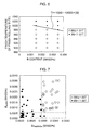
- a relationship between precipitates in the hot-rolled steel strip and a magnetic property after the finish annealing was examined.
- a result of the examination is illustrated in Fig. 7 .
- the horizontal axis indicates a value (mass%) obtained by converting a precipitation amount of MnSe into an amount of Se
- the vertical axis indicates a value (mass%) obtained by converting a precipitation amount of BN into B.
- the horizontal axis corresponds to an amount of Se that has precipitated as MnSe (mass%).
- white circles each indicate that the magnetic flux density B8 was 1.88 T or more
- black squares each indicate that the magnetic flux density B8 was less than 1.88 T.
- the magnetic flux density B8 was low. This indicates that secondary recrystallization was unstable.
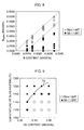
- a relationship between an amount of B that has not precipitated as BN and the magnetic property after the finish annealing was examined.
- a result of the examination is illustrated in Fig. 8 .
- the horizontal axis indicates a B content (mass%)
- the vertical axis indicates the value (mass%) obtained by converting the precipitation amount of BN into B.
- white circles each indicate that the magnetic flux density B8 was 1.88 T or more
- black squares each indicate that the magnetic flux density B8 was less than 1.88 T.
- the magnetic flux density B8 was low. This indicates that the secondary recrystallization was unstable.
- a relationship between a condition of the hot rolling and the magnetic property after the finish annealing was examined.
- a result of the examination is illustrated in Fig. 9 and Fig. 10 .
- the horizontal axis indicates a Mn content (mass%) and the vertical axis indicates a temperature (°C) of slab heating at the time of hot rolling.
- the horizontal axis indicates the B content (mass%) and the vertical axis indicates the temperature (°C) of the slab heating at the time of hot rolling.
- white circles each indicate that the magnetic flux density B8 was 1.88 T or more, and black squares each indicate that the magnetic flux density B8 was less than 1.88 T.
- Fig. 9 indicates a solution temperature T2 (°C) of MnSe expressed by equation (2) below, and a curve in Fig. 10 indicates the solution temperature T3 (°C) of BN expressed by equation (3).
- Fig. 9 it turned out that in the samples in which the slab heating is performed at a temperature determined according to the Mn content or lower, the high magnetic flux density B8 is obtained. Further, it also turned out that the temperature approximately agrees with the solution temperature T2 of MnSe. Further, as illustrated in Fig. 10 , it also turned out that in the samples in which the slab heating is performed at a temperature determined according to the B content or lower, the high magnetic flux density B8 is obtained. Further, it also turned out that the temperature approximately agrees with the solution temperature T3 of BN.
- a precipitation temperature zone of BN is 800°C to 1000°C.
- the present inventors examined a finish temperature of the finish rolling in the hot rolling.
- various silicon steel slabs containing Si: 3.3 mass%, C: 0.06 mass%, acid-soluble Al: 0.028 mass%, N: 0.007 mass%, Mn: 0.1 mass%, Se: 0.007 mass%, and B: 0.001 mass% to 0.004 mass%, and a balance being composed of Fe and inevitable impurities were obtained.
- the silicon steel slabs were heated at a temperature of 1150°C and were subjected to hot rolling.
- rough rolling was performed at 1050°C and then finish rolling was performed at 1020°C to 900°C, and thereby hot-rolled steel strips each having a thickness of 2.3 mm were obtained.
- cooling water was jetted onto the hot-rolled steel strips to then let the hot-rolled steel strips cool down to 550°C, and thereafter the hot-rolled steel strips were cooled down in the atmosphere.
- annealing of the hot-rolled steel strips was performed.
- cold rolling was performed, and thereby cold-rolled steel strips each having a thickness of 0.22 mm were obtained.
- the cold-rolled steel strips were heated at a rate of 15°C/s, and were subjected to decarburization annealing at a temperature of 850°C, and thereby decarburization-annealed steel strips were obtained.
- the decarburization-annealed steel strips were annealed in an ammonia containing atmosphere to increase nitrogen in the steel strips up to 0.023 mass%.
- an annealing separating agent containing MgO as its main component was coated on the steel strips and finish annealing was performed. In this manner, various samples were manufactured.
- a relationship between the finish temperature of the finish rolling in the hot rolling and a magnetic property after the finish annealing was examined.
- a result of the examination is illustrated in Fig. 11 .
- the horizontal axis indicates a B content (mass%)
- the vertical axis indicates the finish temperature Tf of the finish rolling.
- white circles each indicate that the magnetic flux density B8 was 1.91 T or more
- black squares each indicate that the magnetic flux density B8 was less than 1.91 T.
- the finish temperature Tf of the finish rolling satisfies ineqation (4), the high magnetic flux density B8 is obtained. This is conceivably because by controlling the finish temperature Tf of the finish rolling, the precipitation of BN was further promoted.
- cooling water was jetted onto the hot-rolled steel strips to then let the hot-rolled steel strips cool down to 550°C, and thereafter the hot-rolled steel strips were cooled down in the atmosphere.
- annealing of the hot-rolled steel strips was performed.
- cold rolling was performed, and thereby cold-rolled steel strips each having a thickness of 0.22 mm were obtained.
- the cold-rolled steel strips were heated at a rate of 15°C/s, and were subjected to decarburization annealing at a temperature of 850°C, and thereby decarburization-annealed steel strips were obtained.
- the decarburization-annealed steel strips were annealed in an ammonia containing atmosphere to increase nitrogen in the steel strips up to 0.021 mass%.
- an annealing separating agent containing MgO as its main component was coated on the steel strips and finish annealing was performed. In this manner, various samples were manufactured.
- a relationship between precipitates in the hot-rolled steel strip and a magnetic property after the finish annealing was examined.
- a result of the examination is illustrated in Fig. 12 .
- the horizontal axis indicates the sum (mass%) of a value obtained by converting a precipitation amount of MnS into an amount of S and a value obtained by multiplying a value obtained by converting a precipitation amount of MnSe into an amount of Se by 0.5
- the vertical axis indicates a value (mass%) obtained by converting a precipitation amount of BN into B.
- white circles each indicate that the magnetic flux density B8 was 1.88 T or more
- black squares each indicate that the magnetic flux density B8 was less than 1.88 T.
- the magnetic flux density B8 was low. This indicates that secondary recrystallization was unstable.
- a relationship between an amount of B that has not precipitated as BN and the magnetic property after the finish annealing was examined.
- a result of the examination is illustrated in Fig. 13 .
- the horizontal axis indicates a B content (mass%)
- the vertical axis indicates the value (mass%) obtained by converting the precipitation amount of BN into B.
- white circles each indicate that the magnetic flux density B8 was 1.88 T or more
- black squares each indicate that the magnetic flux density B8 was less than 1.88 T.
- the magnetic flux density B8 was low. This indicates that the secondary recrystallization was unstable.
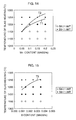
- Fig. 14 a relationship between a condition of the hot rolling and the magnetic property after the finish annealing was examined.
- a result of the examination is illustrated in Fig. 14 and Fig. 15 .
- the horizontal axis indicates a Mn content (mass%) and the vertical axis indicates a temperature (°C) of slab heating at the time of hot rolling.
- the horizontal axis indicates the B content (mass%) and the vertical axis indicates the temperature (°C) of the slab heating at the time of hot rolling.
- white circles each indicate that the magnetic flux density B8 was 1.88 T or more, and black squares each indicate that the magnetic flux density B8 was less than 1.88 T.
- a curve in Fig. 15 indicates the solution temperature T3 (°C) of BN expressed by equation (3).
- the high magnetic flux density B8 is obtained in the samples in which the slab heating is performed at a temperature determined according to the Mn content or lower. Further, it also turned out that the temperature approximately agrees with the solution temperature T1 of MnS and the solution temperature T2 of MnSe. Further, as illustrated in Fig.
- the slab heating is performed at a temperature determined according to the B content or lower, the high magnetic flux density B8 is obtained. Further, it also turned out that the temperature approximately agrees with the solution temperature T3 of BN. That is, it turned out that it is effective to perform the slab heating in a temperature zone where MnS, MnSe, and BN are not completely solid-dissolved.
- a precipitation temperature zone of BN is 800°C to 1000°C.
- the present inventors examined a finish temperature of the finish rolling in the hot rolling.
- various silicon steel slabs containing Si: 3.3 mass%, C: 0.06 mass%, acid-soluble Al: 0.026 mass%, N: 0.009 mass%, Mn: 0.1 mass%, S: 0.005 mass%, Se: 0.007 mass%, and B: 0.001 mass% to 0.004 mass%, and a balance being composed of Fe and inevitable impurities were obtained.
- the silicon steel slabs were heated at a temperature of 1150°C and were subjected to hot rolling.
- hot rolling rough rolling was performed at 1050°C and then finish rolling was performed at 1020°C to 900°C, and thereby hot-rolled steel strips each having a thickness of 2.3 mm were obtained. Then, cooling water was jetted onto the hot-rolled steel strips to then let the hot-rolled steel strips cool down to 550°C, and thereafter the hot-rolled steel strips were cooled down in the atmosphere. Subsequently, annealing of the hot-rolled steel strips was performed. Next, cold rolling was performed, and thereby cold-rolled steel strips each having a thickness of 0.22 mm were obtained.
- the cold-rolled steel strips were heated at a rate of 15°C/s, and were subjected to decarburization annealing at a temperature of 850°C, and thereby decarburization-annealed steel strips were obtained.
- the decarburization-annealed steel strips were annealed in an ammonia containing atmosphere to increase nitrogen in the steel strips up to 0.021 mass%.
- an annealing separating agent containing MgO as its main component was coated on the steel strips and finish annealing was performed. In this manner, various samples were manufactured.
- a relationship between the finish temperature of the finish rolling in the hot rolling and a magnetic property after the finish annealing was examined.
- a result of the examination is illustrated in Fig. 16 .
- the horizontal axis indicates a B content (mass%)
- the vertical axis indicates the finish temperature Tf of the finish rolling.
- white circles each indicate that the magnetic flux density B8 was 1.91 T or more
- black squares each indicate that the magnetic flux density B8 was less than 1.91 T.
- the finish temperature Tf of the finish rolling satisfies inequation (4), the high magnetic flux density B8 is obtained. This is conceivably because by controlling the finish temperature Tf of the finish rolling, the precipitation of BN was further promoted.
- B in a solid solution state is likely to segregate in grain boundaries, and BN that has precipitated independently after the hot rolling is often fine.
- B in a solid solution state and fine BN suppress grain growth at the time of primary recrystallization as strong inhibitors in a low-temperature zone where the decarburization annealing is performed, and in a high-temperature zone where the finish annealing is performed, B in a solid solution state and fine BN do not function as inhibitors locally, thereby turning the grain structure into a mixed grain structure with coarse grains.
- the low-temperature zone primary recrystallized grains are small, so that the magnetic flux density of the grain-oriented electrical steel sheet is reduced.
- the grain structure is turned into the mixed grain structure with coarse grains, so that the secondary recrystallization becomes unstable.
- the silicon steel material used in this embodiment contains Si: 0.8 mass% to 7 mass%, acid-soluble Al: 0.01 mass% to 0.065 mass%, N: 0.004 mass% to 0.012 mass%, Mn: 0.05 mass% to 1 mass%, S and Se: 0.003 mass% to 0.015 mass% in total amount, and B: 0.0005 mass% to 0.0080 mass%, and a C content being 0.085 mass% or less, and a balance being composed of Fe and inevitable impurities.
- the Si increases electrical resistance to reduce a core loss.
- the Si content is set to 7 mass% or less, and is preferably 4.5 mass% or less, and is more preferably 4 mass% or less.
- the Si content is set to 0.8 mass% or more, and is preferably 2 mass% or more, and is more preferably 2.5 mass% or more.
- the C is an element effective for controlling the primary recrystallization structure, but adversely affects the magnetic property.
- the decarburization annealing is performed (step S5) before the finish annealing (step S6).
- the C content exceeds 0.085 mass%, a time taken for the decarburization annealing becomes long, and productivity in industrial production is impaired.
- the C content is set to 0.85 mass% or less, and is preferably 0.07 mass% or less.
- a content of acid-soluble Al falls within a range of 0.01 masses to 0.065 mass%, the secondary recrystallization is stabilized.
- the content of acid-soluble Al is set to be not less than 0.01 mass% nor more than 0.065 mass%.
- the content of acid-soluble Al is preferably 0.02 mass% or more, and is more preferably 0.025 mass% or more.
- the content of acid-soluble Al is preferably 0.04 mass% or less, and is more preferably 0.03 mass% or less.
- the B content bonds to N to precipitate compositely on MnS or MnSe as BN and functions as an inhibitor.
- the B content is set to be not less than 0.0005 mass% nor more than 0.0080 mass%.
- the B content is preferably 0.001% or more, and is more preferably 0.0015% or more.
- the B content is preferably 0.0040% or less, and is more preferably 0.0030% or less.
- an N content is set to 0.004 mass% or more, and is preferably 0.006 mass% or more, and is more preferably 0.007 mass% or more.
- the N content exceeds 0.012 mass%, a hole called a blister occurs in the steel strip at the time of cold rolling.
- the N content is set to 0.012 mass% or less, and is preferably 0.010 mass% or less, and is more preferably 0.009 mass% or less.
- Mn, S and Se produce MnS and MnSe to be a nucleus on which BN precipitates compositely, and composite precipitates function as an inhibitor.
- the Mn content is set to be not less than 0.05 mass% nor more than 1 mass%.
- the Mn content is preferably 0.08 mass% or more, and is more preferably 0.09 mass% or more.
- the Mn content is preferably 0.50 mass% or less, and is more preferably 0.2 mass% or less.
- the content of S and Se is set to be not less than 0.003 mass% nor more than 0.015 mass% in total amount.
- inequation (10) below is preferably satisfied.
- S or Se may be contained in the silicon steel material, or both S and Se may also be contained in the silicon steel material. In the case when both S and Se are contained, it is possible to promote the precipitation of BN more stably and to improve the magnetic property stably.
- Ti forms coarse TiN to affect the precipitation amounts of BN and (Al, Si)N functioning as an inhibitor.
- a Ti content exceeds 0.004 mass%, the good magnetic property is not easily obtained.
- the Ti content is preferably 0.004 mass% or less.
- one or more element(s) selected from a group consisting of Cr, Cu, Ni, P, Mo, Sn, Sb, and Bi may also be contained in the silicon steel material in ranges below.
- Cr improves an oxide layer formed at the time of decarburization annealing, and is effective for forming the glass film made by reaction of the oxide layer and MgO being the main component of the annealing separating agent at the time of finish annealing.
- the Cr content may be set to 0.3 mass% or less.
- Cu increases specific resistance to reduce a core loss.
- a Cu content exceeds 0.4 mass%, the effect is saturated. Further, a surface flaw called “copper scab” is sometimes caused at the time of hot rolling.
- the Cu content may be set to 0.4 mass% or less.
- Ni increases specific resistance to reduce a core loss. Further, Ni controls a metallic structure of the hot-rolled steel strip to improve the magnetic property. However, when a Ni content exceeds 1 mass%, the secondary recrystallization becomes unstable. Thus, the Ni content may be set to 1 mass% or less.
- P increases specific resistance to reduce a core loss.
- a P content exceeds 0.5 mass%, a fracture occurs easily at the time of cold rolling due to embrittlement.
- the P content may be set to 0.5 mass% or less.
- Mo improves a surface property at the time of hot rolling. However, when a Mo content exceeds 0.1 mass%, the effect is saturated. Thus, the Mo content may be set to 0.1 mass% or less.
- Sn and Sb are grain boundary segregation elements.
- the silicon steel material used in this embodiment contains Al, so that there is sometimes a case that Al is oxidized by moisture released from the annealing separating agent depending on the condition of the finish annealing. In this case, variations in inhibitor strength occur depending on the position in the grain-oriented electrical steel sheet, and the magnetic property also sometimes varies.
- the oxidation of Al can be suppressed. That is, Sn and Sb suppress the oxidation of Al to suppress the variations in the magnetic property.
- the oxide layer is not easily formed at the time of decarburization annealing, and thereby the formation of the glass film made by the reaction of the oxide layer and MgO being the main component of the annealing separating agent at the time of finish annealing becomes insufficient. Further, the decarburization is noticeably prevented.
- the content of Sn and Sb may be set to 0.3 mass% or less in total amount.
- Bi stabilizes precipitates such as sulfides to strengthen the function as an inhibitor.
- the Bi content may be set to 0.01 mass% or less.
- the silicon steel material (slab) having the above-described components may be manufactured in a manner that, for example, steel is melted in a converter, an electric furnace, or the like, and the molten steel is subjected to a vacuum degassing treatment according to need, and next is subjected to continuous casting. Further, the silicon steel material may also be manufactured in a manner that in place of the continuous casting, an ingot is made to then be bloomed.
- the thickness of the silicon steel slab is set to, for example, 150 mm to 350 mm, and is preferably set to 220 mm to 280 mm. Further, what is called a thin slab having a thickness of 30 mm to 70 mm may also be manufactured. In the case when the thin slab is manufactured, the rough rolling performed when obtaining the hot-rolled steel strip may be omitted.
- the slab heating is performed (step S1), and the hot rolling (step S2) is performed.
- the conditions of the slab heating and the hot rolling are set such that BN is made to precipitate compositely on MnS and/or MnSe, and that the precipitation amounts of BN, MnS, and MnSe in the hot-rolled steel strip satisfy inequations (5) to (7) below.
- B asBN represents the amount of B that has precipitated as BN (mass%)
- SaSMns represents the amount of S that has precipitated as MnS (mass%)
- Se asMnSe represents the amount of Se that has precipitated as MnSe (mass%).
- a precipitation amount and a solid solution amount of B are controlled such that inequation (5) and inequation (6) are satisfied.
- a certain amount or more of BN is made to precipitate in order to secure an amount of the inhibitors. Further, in the case when the amount of solid-dissolved B is large, there is sometimes a case that unstable fine precipitates are formed in the subsequent processes to adversely affect the primary recrystallization structure.
- MnS and MnSe each function as a nucleus on which BN precipitates compositely.
- the precipitation amounts of MnS and MnSe are controlled such that inequation (7) is satisfied.
- inequation (5) and inequation (7) are derived from Fig. 2 , Fig. 7 , and Fig. 12 . It is found that in the case when B asBN is 0.0005 mass% or more and S asMnS is 0.002 mass% or more, the good magnetic flux density, being the magnetic flux density B8 of 1.88 T or more, is obtained from Fig. 2 . Similarly, it is found that in the case when B asBN is 0.0005 mass% or more and Se asMnSe is 0.004 mass% or more, the good magnetic flux density, being the magnetic flux density B8 of 1.88 T or more, is obtained from Fig. 7 .
- the temperature of the slab heating (step S1) is set so as to satisfy the following conditions.
- the solution temperatures T1 and T2 approximately agree with the upper limit of the slab heating temperature capable of obtaining the magnetic flux density B8 of 1.88 or more.
- the solution temperature T3 approximately agrees with the upper limit of the slab heating temperature capable of obtaining the magnetic flux density B8 of 1.88 or more.
- the temperature of the slab heating is more preferably set so as to satisfy the following conditions as well. This is to make a preferable amount of MnS or MnSe precipitate during the slab heating.
- the slab heating is preferably performed at the temperature T1 and/or the temperature T2 or lower, and at the temperature T3 or lower. Further, if the temperature of the slab heating is the temperature T4 or T5 or lower, a preferable amount of MnS or MnSe precipitates during the slab heating, and thus it becomes possible to make BN precipitate compositely on MnS or MnSe to form effective inhibitors easily.
- the finish temperature Tf of the finish rolling in the hot rolling is set such that inequation (4) below is satisfied. This is to promote the precipitation of BN. Tf ⁇ 1000 - 10000 ⁇ B
- the condition expressed in inequation (4) approximately agrees with the condition capable of obtaining the magnetic flux density B8 of 1.91 T or more.
- the finish temperature Tf of the finish rolling is preferably set to 800°C or higher in terms of the precipitation of BN.
- the annealing of the hot-rolled steel strip is performed (step S3).
- the cold rolling is performed (step S4).
- the cold rolling may be performed only one time, or may also be performed a plurality of times with the intermediate annealing being performed therebetween.
- the final cold rolling rate is preferably set to 80% or more. This is to develop a good primary recrystallization aggregate structure.
- the decarburization annealing is performed (step S5).
- C contained in the steel strip is removed.
- the decarburization annealing is performed in a moist atmosphere, for example. Further, the decarburization annealing is preferably performed at a time such that, for example, a grain diameter obtained by the primary recrystallization becomes 15 ⁇ m or more in a temperature zone of 770°C to 950°C. This is to obtain the good magnetic property.
- the coating of the annealing separating agent and the finish annealing are performed (step S6). As a result, the grains oriented in the ⁇ 110 ⁇ 001> orientation preferentially grow by the secondary recrystallization.
- the nitriding treatment is performed between start of the decarburization annealing and occurrence of the secondary recrystallization in the finish annealing (step S7). This is to form an inhibitor of (Al, Si)N.
- the nitriding treatment may be performed during the decarburization annealing (step S5), or may also be performed during the finish annealing (step S6). In the case when the nitriding treatment is performed during the decarburization annealing, the annealing may be performed in an atmosphere containing a gas having nitriding capability such as ammonia, for example.
- the nitriding treatment may be performed during a heating zone or a soaking zone in a continuous annealing furnace, or the nitriding treatment may also be performed at a stage after the soaking zone.
- a powder having nitriding capability such as MnN, for example, may be added to the annealing separating agent.
- step S7 it is desirable to adjust the degree of nitriding in the nitriding treatment (step S7) and to adjust the compositions of (Al, Si)N in the steel strip after the nitriding treatment.
- the degree of nitriding is preferably controlled so as to satisfy inequation (8) below, and the degree of nitriding is more preferably controlled so as to satisfy inequation (9) below.
- Inequation (8) and inequation (9) indicate an amount of N that is preferable to fix B as BN effective as an inhibitor and an amount of N that is preferable to fix Al as AlN or (Al, Si)N effective as an inhibitor.
- [N] represents an N content (mass%) of a steel strip obtained after the nitriding treatment
- [Al] represents an acid-soluble Al content (mass%) of the steel strip obtained after the nitriding treatment
- [B] represents a B content (mass%) of the steel strip obtained after the nitriding treatment
- [Ti] represents a Ti content (mass%) of the steel strip obtained after the nitriding treatment.
- the method of the finish annealing is also not limited in particular.
- the inhibitors are strengthened by BN, so that a heating rate in a temperature range of 1000°C to 1100°C is preferably set to 15°C/h or less in a heating process of the finish annealing. Further, in place of controlling the heating rate, it is also effective to perform isothermal annealing in which the steel strip is maintained in the temperature range of 1000°C to 1100°C for 10 hours or longer.
- the finish temperature Tf is necessary to be 980°C or lower based on inequation (4). Then, as listed in Table 4, in Examples No. 4A to 4C each satisfying the condition, the good magnetic flux density was obtained, but in Comparative Example No. 4D not satisfying the condition, the magnetic flux density was low.
- decarburization annealing was performed in a moist atmosphere gas at 830°C for 100 seconds, and thereby decarburization-annealed steel strips were obtained.
- the decarburization-annealed steel strips were annealed in an ammonia containing atmosphere to increase nitrogen in the steel strips up to 0.024 mass%.
- an annealing separating agent containing MgO as its main component was coated on the steel strips, and the steel strips were heated up to 1000°C at a rate of 15°C/h, and further were heated up to 1200°C at a rate listed in Table 6 (5°C/h to 30°C/h) and were finish annealed.
- a magnetic property (the magnetic flux density B8) was measured. A result of the measurement is listed in Table 6.
- Example No. 6A to No. 6C the heating rate in a temperature range of 1000°C to 1100°C was set to 15°C/h or less, so that the particularly good magnetic flux density was obtained.
- Example No. 6D the heating rate in the temperature range exceeded 15°C/h, so that the magnetic flux density was slightly lower than those in Examples No. 6A to No. 6C.
- Example No. 7A the steel strip was heated up to 1200°C at a rate of 15°C/h and was finish annealed. Further, in Examples No. 7B to No.
- the steel strips were heated up to a temperature listed in Table 7 (1000°C to 1150°C) at a rate of 30°C/h and were kept for 10 hours at the temperature, and thereafter were heated up to 1200°C at a rate of 30°C/h and were finish annealed. Then, similarly to the fourth experiment, a magnetic property (the magnetic flux density B8) was measured. A result of the measurement is listed in Table 7.
- Example No. 7A the heating rate in a temperature range of 1000°C to 1100°C was set to 15°C/h or less, so that the particularly good magnetic flux density was obtained. Further, in Examples No. 7B to 7D, the steel strips were kept in the temperature range of 1000°C to 1100°C for 10 hours, so that the particularly good magnetic flux density was obtained. On the other hand, in Example No. 7E, the temperature at which the steel strip was kept for 10 hours exceeded 1100°C, so that the magnetic flux density was slightly lower than those in Examples No. 7A to No. 7D.
- the decarburization-annealed steel strips were annealed in an ammonia containing atmosphere to increase nitrogen in the steel strips up to 0.022 mass%.
- an annealing separating agent containing MgO as its main component was coated on the steel strips, and the steel strips were heated up to 1200°C at a rate of 15°C/h and were finish annealed.
- a magnetic property (the magnetic flux density B8) was measured. A result of the measurement is listed in Table 10.
- Example No. 10A decarburization annealing was performed in a moist atmosphere gas at 830°C for 100 seconds, and thereby a decarburization-annealed steel strip was obtained.
- Example No. 10B decarburization annealing was performed in a moist atmosphere gas at 830°C for 100 seconds, and further annealing was performed in an ammonia containing atmosphere, and thereby a decarburization-annealed steel strip having an N content of 0.021 mass% was obtained.
- Example No. 10B decarburization annealing was performed in a moist atmosphere gas at 830°C for 100 seconds, and further annealing was performed in an ammonia containing atmosphere, and thereby a decarburization-annealed steel strip having an N content of 0.021 mass% was obtained.
- decarburization annealing was performed in a moist atmosphere gas at 860°C for 100 seconds, and thereby a decarburization-annealed steel strip having an N content of 0.021 mass% was obtained. In this manner, three types of the decarburization-annealed steel strips were obtained.
- Example No. 10B in which the nitriding treatment was performed after the decarburization annealing
- Example No. 10C in which the nitriding treatment was performed during the decarburization annealing
- the magnetic flux density was low.
- the numerical value in the section of "NITRIDING TREATMENT" of Comparative Example No. 10A in Table 11 is a value obtained from the composition of the decarburization-annealed steel strip.
- the finish temperature Tf is necessary to be 980°C or lower based on inequation (4). Then, as listed in Table 15, in Examples No. 14A to 14C each satisfying the condition, the good magnetic flux density was obtained, but in Comparative Example No. 14D not satisfying the condition, the magnetic flux density was low.
- Example No. 15C and No. 15D in which an N content after the nitriding treatment satisfied the relation of inequation (8) and the relation of inequation (9), the particularly good magnetic flux density was obtained.
- Example No. 15B in which an N content after the nitriding treatment satisfied the relation of inequation (8) but did not satisfy the relation of inequation (9), the magnetic flux density was slightly lower than those in Examples No. 15C and No. 15D.
- Example No. 15A in which an N content after the nitriding treatment did not satisfy the relation of inequation (8) and the relation of inequation (9), the magnetic flux density was slightly lower than that in Example No. 15B.
- decarburization annealing was performed in a moist atmosphere gas at 840°C for 100 seconds, and thereby decarburization-annealed steel strips were obtained.
- the decarburization-annealed steel strips were annealed in an ammonia containing atmosphere to increase nitrogen in the steel strips up to 0.024 mass%.
- an annealing separating agent containing MgO as its main component was coated on the steel strips, and the steel strips were heated up to 1000°C at a rate of 15°C/h, and further were heated up to 1200°C at a rate listed in Table 17 (5°C/h to 30°C/h) and were finish annealed.
- a magnetic property (the magnetic flux density B8) was measured. A result of the measurement is listed in Table 17.
- Example No. 16A to No. 16C the heating rate in a temperature range of 1000°C to 1100°C was set to 15°C/h or less, so that the particularly good magnetic flux density was obtained.
- Example No. 16D the heating rate in the temperature range exceeded 15°C/h, so that the magnetic flux density was slightly lower than those in Examples No. 16A to No. 16C.
- Example No. 17A the steel strip was heated up to 1200°C at a rate of 15°C/h and was finish annealed. Further, in Examples No. 17B to No.
- the steel strips were heated up to a temperature listed in Table 18 (1000°C to 1150°C) at a rate of 30°C/h and were kept for 10 hours at the temperature, and thereafter were heated up to 1200°C at a rate of 30°C/h and were finish annealed. Then, similarly to the fourth experiment, a magnetic property (the magnetic flux density B8) was measured. A result of the measurement is listed in Table 18.
- Example No. 17A the heating rate in a temperature range of 1000°C to 1100°C was set to 15°C/h or less, so that the particularly good magnetic flux density was obtained. Further, in Examples No. 17B to 17D, the steel strips were kept in the temperature range of 1000°C to 1100°C for 10 hours, so that the particularly good magnetic flux density was obtained. On the other hand, in Example No. 17E, the temperature at which the steel strip was kept for 10 hours exceeded 1100°C, so that the magnetic flux density was slightly lower than those in Examples No. 17A to No. 17D.
- the decarburization-annealed steel strips were annealed in an ammonia containing atmosphere to increase nitrogen in the steel strips up to 0.022 mass%.
- an annealing separating agent containing MgO as its main component was coated on the steel strips, and the steel strips were heated up to 1200°C at a rate of 15°C/h and were finish annealed.
- a magnetic property (the magnetic flux density B8) was measured. A result of the measurement is listed in Table 21.
- Example No. 20A decarburization annealing was performed in a moist atmosphere gas at 830°C for 100 seconds, and thereby a decarburization-annealed steel strip was obtained.
- Example No. 20B decarburization annealing was performed in a moist atmosphere gas at 830°C for 100 seconds, and further annealing was performed in an ammonia containing atmosphere, and thereby a decarburization-annealed steel strip having an N content of 0.023 mass% was obtained.
- Example No. 20B decarburization annealing was performed in a moist atmosphere gas at 830°C for 100 seconds, and further annealing was performed in an ammonia containing atmosphere, and thereby a decarburization-annealed steel strip having an N content of 0.023 mass% was obtained.
- decarburization annealing was performed in a moist atmosphere gas at 860°C for 100 seconds, and thereby a decarburization-annealed steel strip having an N content of 0.023 mass% was obtained. In this manner, three types of the decarburization-annealed steel strips were obtained.
- Example No. 20B in which the nitriding treatment was performed after the decarburization annealing
- Example No. 20C in which the nitriding treatment was performed during the decarburization annealing
- the magnetic flux density was low.
- the numerical value in the section of "NITRIDING TREATMENT" of Comparative Example No. 20A in Table 22 is a value obtained from the composition of the decarburization-annealed steel strip.
- the finish temperature Tf is necessary to be 980°C or lower based on inequation (4). Then, as listed in Table 26, in Examples No. 24A to 24C each satisfying the condition, the good magnetic flux density was obtained, but in Comparative Example No. 24D not satisfying the condition, the magnetic flux density was low.
- Example No. 26A to No. 26C the heating rate in a temperature range of 1000°C to 1100°C was set to 15°C/h or less, so that the particularly good magnetic flux density was obtained.
- Example No. 26D the heating rate in the temperature range exceeded 15°C/h, so that the magnetic flux density was slightly lower than those in Examples No. 26A to No. 26C.
- Example No. 27A the steel strip was heated up to 1200°C at a rate of 15°C/h and was finish annealed. Further, in Examples No.
- the steel strips were heated up to a temperature listed in Table 29 (1000°C to 1150°C) at a rate of 30°C/h and were kept for 10 hours at the temperature, and thereafter were heated up to 1200°C at a rate of 30°C/h and were finish annealed. Then, similarly to the fourth experiment, a magnetic property (the magnetic flux density B8) was measured. A result of the measurement is listed in Table 29.
- Example No. 27A the heating rate in a temperature range of 1000°C to 1100°C was set to 15°C/h or less, so that the particularly good magnetic flux density was obtained. Further, in Examples No. 27B to 27D, the steel strips were kept in the temperature range of 1000°C to 1100°C for 10 hours, so that the particularly good magnetic flux density was obtained. On the other hand, in Example No. 27E, the temperature at which the steel strip was kept for 10 hours exceeded 1100°C, so that the magnetic flux density was slightly lower than those in Examples No. 27A to No. 27D.
- the decarburization-annealed steel strips were annealed in an ammonia containing atmosphere to increase nitrogen in the steel strips up to 0.023 mass%.
- an annealing separating agent containing MgO as its main component was coated on the steel strips, and the steel strips were heated up to 1200°C at a rate of 15°C/h and were finish annealed.
- a magnetic property (the magnetic flux density B8) was measured. A result of the measurement is listed in Table 32.
- Example No. 30A decarburization annealing was performed in a moist atmosphere gas at 830°C for 100 seconds, and thereby a decarburization-annealed steel strip was obtained.
- Example No. 30B decarburization annealing was performed in a moist atmosphere gas at 830°C for 100 seconds, and further annealing was performed in an ammonia containing atmosphere, and thereby a decarburization-annealed steel strip having an N content of 0.022 mass% was obtained.
- Example No. 30B decarburization annealing was performed in a moist atmosphere gas at 830°C for 100 seconds, and further annealing was performed in an ammonia containing atmosphere, and thereby a decarburization-annealed steel strip having an N content of 0.022 mass% was obtained.
- decarburization annealing was performed in a moist atmosphere gas at 860°C for 100 seconds, and thereby a decarburization-annealed steel strip having an N content of 0.022 mass% was obtained. In this manner, three types of the decarburization-annealed steel strips were obtained.
- Example No. 30B in which the nitriding treatment was performed after the decarburization annealing
- Example No. 30C in which the nitriding treatment was performed during the decarburization annealing
- the magnetic flux density was low.
- the numerical value in the section of "NITRIDING TREATMENT" of Comparative Example No. 30A in Table 33 is a value obtained from the composition of the decarburization-annealed steel strip.
- the present invention can be utilized in, for example, an industry of manufacturing electrical steel sheets and an industry in which electrical steel sheets are used.
Landscapes
- Chemical & Material Sciences (AREA)
- Engineering & Computer Science (AREA)
- Mechanical Engineering (AREA)
- Organic Chemistry (AREA)
- Metallurgy (AREA)
- Materials Engineering (AREA)
- Physics & Mathematics (AREA)
- Thermal Sciences (AREA)
- Crystallography & Structural Chemistry (AREA)
- Manufacturing & Machinery (AREA)
- Electromagnetism (AREA)
- Chemical Kinetics & Catalysis (AREA)
- Dispersion Chemistry (AREA)
- Power Engineering (AREA)
- Manufacturing Of Steel Electrode Plates (AREA)
- Soft Magnetic Materials (AREA)
- Solid-Phase Diffusion Into Metallic Material Surfaces (AREA)
Priority Applications (1)
| Application Number | Priority Date | Filing Date | Title |
|---|---|---|---|
| PL10799829T PL2455497T3 (pl) | 2009-07-13 | 2010-07-13 | Sposób wytwarzania blachy cienkiej ze stali elektrotechnicznej o ziarnach zorientowanych |
Applications Claiming Priority (4)
| Application Number | Priority Date | Filing Date | Title |
|---|---|---|---|
| JP2009165011 | 2009-07-13 | ||
| JP2009165058 | 2009-07-13 | ||
| JP2010013247 | 2010-01-25 | ||
| PCT/JP2010/061818 WO2011007771A1 (ja) | 2009-07-13 | 2010-07-13 | 方向性電磁鋼板の製造方法 |
Publications (3)
| Publication Number | Publication Date |
|---|---|
| EP2455497A1 true EP2455497A1 (de) | 2012-05-23 |
| EP2455497A4 EP2455497A4 (de) | 2017-07-05 |
| EP2455497B1 EP2455497B1 (de) | 2019-01-30 |
Family
ID=43449378
Family Applications (1)
| Application Number | Title | Priority Date | Filing Date |
|---|---|---|---|
| EP10799829.6A Active EP2455497B1 (de) | 2009-07-13 | 2010-07-13 | Herstellungsverfahren eines kornorientierten elektrostahlblechs |
Country Status (9)
| Country | Link |
|---|---|
| US (1) | US8366836B2 (de) |
| EP (1) | EP2455497B1 (de) |
| JP (1) | JP4709949B2 (de) |
| KR (1) | KR101351149B1 (de) |
| CN (1) | CN102471818B (de) |
| BR (1) | BR112012000800B1 (de) |
| PL (1) | PL2455497T3 (de) |
| RU (1) | RU2499846C2 (de) |
| WO (1) | WO2011007771A1 (de) |
Cited By (2)
| Publication number | Priority date | Publication date | Assignee | Title |
|---|---|---|---|---|
| EP2664689A4 (de) * | 2011-01-12 | 2014-07-30 | Nippon Steel & Sumitomo Metal Corp | Kornorientiertes magnetisches stahlblech und herstellungsverfahren dafür |
| RU2594543C1 (ru) * | 2012-08-30 | 2016-08-20 | Баошан Айрон Энд Стил Ко., Лтд. | Текстурированная кремнистая сталь с высокой магнитной индукцией и способ ее производства |
Families Citing this family (19)
| Publication number | Priority date | Publication date | Assignee | Title |
|---|---|---|---|---|
| EP2455497B1 (de) | 2009-07-13 | 2019-01-30 | Nippon Steel & Sumitomo Metal Corporation | Herstellungsverfahren eines kornorientierten elektrostahlblechs |
| KR101351712B1 (ko) * | 2009-07-17 | 2014-01-14 | 신닛테츠스미킨 카부시키카이샤 | 방향성 전자기 강판의 제조 방법 |
| JP2012144776A (ja) * | 2011-01-12 | 2012-08-02 | Nippon Steel Corp | 方向性電磁鋼板の製造方法 |
| JP2012144777A (ja) * | 2011-01-12 | 2012-08-02 | Nippon Steel Corp | 電磁鋼板素材及び方向性電磁鋼板の製造方法 |
| KR101756606B1 (ko) | 2013-09-26 | 2017-07-10 | 제이에프이 스틸 가부시키가이샤 | 방향성 전기 강판의 제조 방법 |
| CN103695791B (zh) * | 2013-12-11 | 2015-11-18 | 武汉钢铁(集团)公司 | 一种高磁感取向硅钢及生产方法 |
| BR112018005469B1 (pt) * | 2015-09-28 | 2021-08-31 | Nippon Steel Corporation | Chapa de aço elétrico com grão orientado, chapa de aço laminada a quente para chapa de aço elétrico com grão orientado e seus métodos de produção |
| US11466338B2 (en) | 2018-01-25 | 2022-10-11 | Nippon Steel Corporation | Grain oriented electrical steel sheet |
| RU2740749C1 (ru) * | 2018-01-25 | 2021-01-20 | Ниппон Стил Корпорейшн | Лист из электротехнической стали с ориентированной зеренной структурой |
| CN110093486B (zh) * | 2018-01-31 | 2021-08-17 | 宝山钢铁股份有限公司 | 一种耐消除应力退火的低铁损取向硅钢的制造方法 |
| PL3913100T3 (pl) | 2019-01-16 | 2024-01-29 | Nippon Steel Corporation | Blacha cienka ze stali elektrotechnicznej o ziarnach zorientowanych |
| WO2020188783A1 (ja) * | 2019-03-20 | 2020-09-24 | 日本製鉄株式会社 | 無方向性電磁鋼板およびその製造方法 |
| KR102709639B1 (ko) * | 2019-09-19 | 2024-09-26 | 닛폰세이테츠 가부시키가이샤 | 방향성 전자 강판 |
| JP7338511B2 (ja) * | 2020-03-03 | 2023-09-05 | Jfeスチール株式会社 | 方向性電磁鋼板の製造方法 |
| KR20230094748A (ko) * | 2021-12-21 | 2023-06-28 | 주식회사 포스코 | 방향성 전기강판 및 이의 제조방법 |
| EP4474494A4 (de) | 2022-04-04 | 2025-07-30 | Nippon Steel Corp | Kornorientiertes elektromagnetisches stahlblech und herstellungsverfahren dafür |
| US20250154631A1 (en) | 2022-04-04 | 2025-05-15 | Nippon Steel Corporation | Grain-oriented electrical steel sheet and method of production of same |
| JP7836392B2 (ja) | 2022-10-04 | 2026-03-26 | 日本製鉄株式会社 | 方向性電磁鋼板およびその製造方法 |
| JP7659219B2 (ja) | 2022-10-04 | 2025-04-09 | 日本製鉄株式会社 | 方向性電磁鋼板およびその製造方法 |
Family Cites Families (34)
| Publication number | Priority date | Publication date | Assignee | Title |
|---|---|---|---|---|
| JPS5113469B2 (de) | 1972-10-13 | 1976-04-28 | ||
| US3905843A (en) | 1974-01-02 | 1975-09-16 | Gen Electric | Method of producing silicon-iron sheet material with boron addition and product |
| US3905842A (en) | 1974-01-07 | 1975-09-16 | Gen Electric | Method of producing silicon-iron sheet material with boron addition and product |
| JPS57207114A (en) * | 1981-06-16 | 1982-12-18 | Nippon Steel Corp | Manufacture of anisotropic electric steel plate |
| JPS6240315A (ja) | 1985-08-15 | 1987-02-21 | Nippon Steel Corp | 磁束密度の高い一方向性珪素鋼板の製造方法 |
| JPH0686631B2 (ja) | 1988-05-11 | 1994-11-02 | 新日本製鐵株式会社 | 磁束密度の高い一方向性電磁鋼板の製造方法 |
| JPH0686630B2 (ja) | 1987-11-20 | 1994-11-02 | 新日本製鐵株式会社 | 磁束密度の高い一方向性珪素鋼板の製造方法 |
| EP0321695B1 (de) | 1987-11-20 | 1993-07-21 | Nippon Steel Corporation | Verfahren zur Herstellung von kornorientierten Elektrostahlblechen mit hoher Flussdichte |
| US5186762A (en) | 1989-03-30 | 1993-02-16 | Nippon Steel Corporation | Process for producing grain-oriented electrical steel sheet having high magnetic flux density |
| JPH0689404B2 (ja) | 1989-03-30 | 1994-11-09 | 新日本製鐵株式会社 | 磁束密度の高い一方向性電磁鋼板の製造方法 |
| JP2782086B2 (ja) | 1989-05-29 | 1998-07-30 | 新日本製鐵株式会社 | 磁気特性、皮膜特性ともに優れた一方向性電磁鋼板の製造方法 |
| RU2041268C1 (ru) * | 1991-10-25 | 1995-08-09 | Армко Инк. | Способ получения высококремнистой электротехнической стали |
| KR960006448B1 (ko) * | 1992-08-05 | 1996-05-16 | 가와사끼 세이데쓰 가부시끼가이샤 | 저철손 방향성 전자강판의 제조방법 |
| RU2096516C1 (ru) * | 1996-01-10 | 1997-11-20 | Акционерное общество "Новолипецкий металлургический комбинат" | Сталь кремнистая электротехническая и способ ее обработки |
| JP3674183B2 (ja) * | 1996-10-11 | 2005-07-20 | Jfeスチール株式会社 | 方向性電磁鋼板の製造方法 |
| JP3415377B2 (ja) * | 1996-11-13 | 2003-06-09 | Jfeスチール株式会社 | 極めて鉄損の低い高磁束密度方向性電磁鋼板の製造方法 |
| US5885371A (en) | 1996-10-11 | 1999-03-23 | Kawasaki Steel Corporation | Method of producing grain-oriented magnetic steel sheet |
| KR100440994B1 (ko) | 1996-10-21 | 2004-10-21 | 제이에프이 스틸 가부시키가이샤 | 방향성전자강판및그제조방법 |
| JPH1150153A (ja) | 1997-08-01 | 1999-02-23 | Nippon Steel Corp | 磁束密度が極めて高い方向性電磁鋼板の製造方法 |
| JP3357603B2 (ja) | 1998-05-21 | 2002-12-16 | 川崎製鉄株式会社 | 極めて鉄損の低い高磁束密度方向性電磁鋼板の製造方法 |
| KR19990088437A (ko) | 1998-05-21 | 1999-12-27 | 에모또 간지 | 철손이매우낮은고자속밀도방향성전자강판및그제조방법 |
| JP4653266B2 (ja) | 1998-10-22 | 2011-03-16 | 新日本製鐵株式会社 | 一方向性電磁鋼板の製造方法 |
| JP2000282142A (ja) | 1999-03-29 | 2000-10-10 | Nippon Steel Corp | 一方向性電磁鋼板の製造方法 |
| KR100359622B1 (ko) * | 1999-05-31 | 2002-11-07 | 신닛뽄세이테쯔 카부시키카이샤 | 고자장 철손 특성이 우수한 고자속밀도 일방향성 전자 강판 및 그의 제조방법 |
| JP3488181B2 (ja) | 1999-09-09 | 2004-01-19 | 新日本製鐵株式会社 | 磁気特性に優れた一方向性電磁鋼板の製造方法 |
| EP1162280B1 (de) * | 2000-06-05 | 2013-08-07 | Nippon Steel & Sumitomo Metal Corporation | Verfahren zur Herstellung eines kornorientierten Elektrobleches mit ausgezeichneten magnetischen Eigenschaften |
| JP4585144B2 (ja) * | 2001-05-22 | 2010-11-24 | 新日本製鐵株式会社 | 磁気特性の優れた一方向性電磁鋼板の製造方法 |
| CN100381598C (zh) * | 2004-12-27 | 2008-04-16 | 宝山钢铁股份有限公司 | 一种取向硅钢及其生产方法和装置 |
| BRPI0712010B1 (pt) * | 2006-05-24 | 2014-10-29 | Nippon Steel & Sumitomo Metal Corp | Métodos de produção de uma chapa de aço elétrico com grãos orientados |
| KR101062127B1 (ko) * | 2006-05-24 | 2011-09-02 | 신닛뽄세이테쯔 카부시키카이샤 | 자속 밀도가 높은 방향성 전자기 강판의 제조 방법 |
| CN101358273B (zh) * | 2008-09-05 | 2010-12-01 | 首钢总公司 | 一种低温取向电工钢的生产方法 |
| EP2455497B1 (de) | 2009-07-13 | 2019-01-30 | Nippon Steel & Sumitomo Metal Corporation | Herstellungsverfahren eines kornorientierten elektrostahlblechs |
| KR101351712B1 (ko) * | 2009-07-17 | 2014-01-14 | 신닛테츠스미킨 카부시키카이샤 | 방향성 전자기 강판의 제조 방법 |
| JP6245285B2 (ja) | 2015-03-30 | 2017-12-13 | Jfeスチール株式会社 | 人工浅場又は干潟 |
-
2010
- 2010-07-13 EP EP10799829.6A patent/EP2455497B1/de active Active
- 2010-07-13 WO PCT/JP2010/061818 patent/WO2011007771A1/ja not_active Ceased
- 2010-07-13 BR BR112012000800-5A patent/BR112012000800B1/pt active IP Right Grant
- 2010-07-13 JP JP2010540969A patent/JP4709949B2/ja active Active
- 2010-07-13 RU RU2012101110/02A patent/RU2499846C2/ru active
- 2010-07-13 US US13/381,294 patent/US8366836B2/en active Active
- 2010-07-13 CN CN2010800314899A patent/CN102471818B/zh active Active
- 2010-07-13 PL PL10799829T patent/PL2455497T3/pl unknown
- 2010-07-13 KR KR1020127000903A patent/KR101351149B1/ko active Active
Non-Patent Citations (1)
| Title |
|---|
| See references of WO2011007771A1 * |
Cited By (4)
| Publication number | Priority date | Publication date | Assignee | Title |
|---|---|---|---|---|
| EP2664689A4 (de) * | 2011-01-12 | 2014-07-30 | Nippon Steel & Sumitomo Metal Corp | Kornorientiertes magnetisches stahlblech und herstellungsverfahren dafür |
| US10208372B2 (en) | 2011-01-12 | 2019-02-19 | Nippon Steel & Sumitomo Metal Corporation | Grain-oriented electrical steel sheet and manufacturing method thereof |
| RU2594543C1 (ru) * | 2012-08-30 | 2016-08-20 | Баошан Айрон Энд Стил Ко., Лтд. | Текстурированная кремнистая сталь с высокой магнитной индукцией и способ ее производства |
| EP2891728A4 (de) * | 2012-08-30 | 2016-08-31 | Baoshan Iron & Steel | Kornorientierter siliciumstahl mit hoher magnetischer induktion und herstellungsverfahren dafür |
Also Published As
| Publication number | Publication date |
|---|---|
| US20120103474A1 (en) | 2012-05-03 |
| RU2012101110A (ru) | 2013-08-20 |
| EP2455497A4 (de) | 2017-07-05 |
| CN102471818A (zh) | 2012-05-23 |
| WO2011007771A1 (ja) | 2011-01-20 |
| RU2499846C2 (ru) | 2013-11-27 |
| JP4709949B2 (ja) | 2011-06-29 |
| JPWO2011007771A1 (ja) | 2012-12-27 |
| US8366836B2 (en) | 2013-02-05 |
| KR20120030140A (ko) | 2012-03-27 |
| BR112012000800A2 (pt) | 2016-02-23 |
| BR112012000800B1 (pt) | 2021-10-05 |
| CN102471818B (zh) | 2013-10-09 |
| PL2455497T3 (pl) | 2019-07-31 |
| KR101351149B1 (ko) | 2014-01-14 |
| EP2455497B1 (de) | 2019-01-30 |
Similar Documents
| Publication | Publication Date | Title |
|---|---|---|
| EP2455497A1 (de) | Verfahren zur herstellung eines elektromagnetischen stahlblechs mit ausgerichteter körnung | |
| EP2455498B1 (de) | Verfahren zur herstellung eines kornorientierten magnetischen stahlblechs | |
| JP3172439B2 (ja) | 高い体積抵抗率を有する粒子方向性珪素鋼およびその製造法 | |
| EP2330223B1 (de) | Verfahren zur herstellung eines kornorientierten elektrostahlblechs | |
| EP3243921B1 (de) | Nichtorientiertes elektromagnetisches stahlblech und verfahren zur herstellung davon | |
| EP2578706B1 (de) | Verfahren zur herstellung eines kornorientierten elektrostahlblechs | |
| JP6844125B2 (ja) | 方向性電磁鋼板の製造方法 | |
| EP2876173A1 (de) | Verfahren zur herstellung kornorientierter elektrobleche | |
| JP2013100602A (ja) | 高透磁率方向性電磁鋼材 | |
| EP2418294B1 (de) | Verfahren zum behandeln von stahl für ein kornorientiertes elektrostahlblech und herstellungsverfahren für ein kornorientiertes elektrostahlblech | |
| EP2537947A1 (de) | Herstellungsverfahren für ein kornorientiertes elektromagnetisches stahlblech | |
| JP4598702B2 (ja) | 磁気特性が優れた高Si含有方向性電磁鋼板の製造方法 | |
| JP2022509864A (ja) | 方向性電磁鋼板およびその製造方法 | |
| JP2021509149A (ja) | 方向性電磁鋼板およびその製造方法 | |
| JP7736157B2 (ja) | 無方向性電磁鋼板とその製造方法 | |
| JP7037657B2 (ja) | 方向性電磁鋼板およびその製造方法 | |
| JP2005002401A (ja) | 無方向性電磁鋼板の製造方法 | |
| JP4283533B2 (ja) | 一方向性電磁鋼板の製造方法 | |
| JP2012144776A (ja) | 方向性電磁鋼板の製造方法 | |
| EP4455342A1 (de) | Kornorientiertes elektrostahlblech und herstellungsverfahren dafür | |
| EP4265767A1 (de) | Kornorientiertes elektrostahlblech und herstellungsverfahren dafür | |
| CN104302801A (zh) | 冲裁加工导致的铁损特性劣化较小的无方向性电磁钢板 |
Legal Events
| Date | Code | Title | Description |
|---|---|---|---|
| PUAI | Public reference made under article 153(3) epc to a published international application that has entered the european phase |
Free format text: ORIGINAL CODE: 0009012 |
|
| 17P | Request for examination filed |
Effective date: 20120209 |
|
| AK | Designated contracting states |
Kind code of ref document: A1 Designated state(s): AL AT BE BG CH CY CZ DE DK EE ES FI FR GB GR HR HU IE IS IT LI LT LU LV MC MK MT NL NO PL PT RO SE SI SK SM TR |
|
| DAX | Request for extension of the european patent (deleted) | ||
| RAP1 | Party data changed (applicant data changed or rights of an application transferred) |
Owner name: NIPPON STEEL & SUMITOMO METAL CORPORATION |
|
| RA4 | Supplementary search report drawn up and despatched (corrected) |
Effective date: 20170608 |
|
| RIC1 | Information provided on ipc code assigned before grant |
Ipc: C21D 8/12 20060101AFI20170601BHEP Ipc: B21B 3/02 20060101ALI20170601BHEP Ipc: H01F 1/16 20060101ALI20170601BHEP Ipc: C22C 38/00 20060101ALI20170601BHEP Ipc: C22C 38/60 20060101ALI20170601BHEP Ipc: C22C 38/02 20060101ALI20170601BHEP Ipc: C22C 38/06 20060101ALI20170601BHEP Ipc: C22C 38/04 20060101ALI20170601BHEP Ipc: C23C 8/26 20060101ALI20170601BHEP |
|
| GRAP | Despatch of communication of intention to grant a patent |
Free format text: ORIGINAL CODE: EPIDOSNIGR1 |
|
| STAA | Information on the status of an ep patent application or granted ep patent |
Free format text: STATUS: GRANT OF PATENT IS INTENDED |
|
| INTG | Intention to grant announced |
Effective date: 20180803 |
|
| GRAS | Grant fee paid |
Free format text: ORIGINAL CODE: EPIDOSNIGR3 |
|
| GRAA | (expected) grant |
Free format text: ORIGINAL CODE: 0009210 |
|
| STAA | Information on the status of an ep patent application or granted ep patent |
Free format text: STATUS: THE PATENT HAS BEEN GRANTED |
|
| AK | Designated contracting states |
Kind code of ref document: B1 Designated state(s): AL AT BE BG CH CY CZ DE DK EE ES FI FR GB GR HR HU IE IS IT LI LT LU LV MC MK MT NL NO PL PT RO SE SI SK SM TR |
|
| REG | Reference to a national code |
Ref country code: GB Ref legal event code: FG4D |
|
| REG | Reference to a national code |
Ref country code: CH Ref legal event code: EP |
|
| REG | Reference to a national code |
Ref country code: AT Ref legal event code: REF Ref document number: 1093318 Country of ref document: AT Kind code of ref document: T Effective date: 20190215 |
|
| REG | Reference to a national code |
Ref country code: IE Ref legal event code: FG4D |
|
| REG | Reference to a national code |
Ref country code: DE Ref legal event code: R096 Ref document number: 602010056873 Country of ref document: DE |
|
| REG | Reference to a national code |
Ref country code: DE Ref legal event code: R082 Ref document number: 602010056873 Country of ref document: DE Representative=s name: VOSSIUS & PARTNER PATENTANWAELTE RECHTSANWAELT, DE Ref country code: DE Ref legal event code: R081 Ref document number: 602010056873 Country of ref document: DE Owner name: NIPPON STEEL CORPORATION, JP Free format text: FORMER OWNER: NIPPON STEEL & SUMITOMO METAL CORPORATION, TOKYO, JP |
|
| REG | Reference to a national code |
Ref country code: LT Ref legal event code: MG4D |
|
| REG | Reference to a national code |
Ref country code: NL Ref legal event code: MP Effective date: 20190130 |
|
| RAP2 | Party data changed (patent owner data changed or rights of a patent transferred) |
Owner name: NIPPON STEEL CORPORATION |
|
| PG25 | Lapsed in a contracting state [announced via postgrant information from national office to epo] |
Ref country code: FI Free format text: LAPSE BECAUSE OF FAILURE TO SUBMIT A TRANSLATION OF THE DESCRIPTION OR TO PAY THE FEE WITHIN THE PRESCRIBED TIME-LIMIT Effective date: 20190130 Ref country code: NO Free format text: LAPSE BECAUSE OF FAILURE TO SUBMIT A TRANSLATION OF THE DESCRIPTION OR TO PAY THE FEE WITHIN THE PRESCRIBED TIME-LIMIT Effective date: 20190430 Ref country code: ES Free format text: LAPSE BECAUSE OF FAILURE TO SUBMIT A TRANSLATION OF THE DESCRIPTION OR TO PAY THE FEE WITHIN THE PRESCRIBED TIME-LIMIT Effective date: 20190130 Ref country code: SE Free format text: LAPSE BECAUSE OF FAILURE TO SUBMIT A TRANSLATION OF THE DESCRIPTION OR TO PAY THE FEE WITHIN THE PRESCRIBED TIME-LIMIT Effective date: 20190130 Ref country code: PT Free format text: LAPSE BECAUSE OF FAILURE TO SUBMIT A TRANSLATION OF THE DESCRIPTION OR TO PAY THE FEE WITHIN THE PRESCRIBED TIME-LIMIT Effective date: 20190530 Ref country code: LT Free format text: LAPSE BECAUSE OF FAILURE TO SUBMIT A TRANSLATION OF THE DESCRIPTION OR TO PAY THE FEE WITHIN THE PRESCRIBED TIME-LIMIT Effective date: 20190130 Ref country code: NL Free format text: LAPSE BECAUSE OF FAILURE TO SUBMIT A TRANSLATION OF THE DESCRIPTION OR TO PAY THE FEE WITHIN THE PRESCRIBED TIME-LIMIT Effective date: 20190130 |
|
| REG | Reference to a national code |
Ref country code: AT Ref legal event code: MK05 Ref document number: 1093318 Country of ref document: AT Kind code of ref document: T Effective date: 20190130 |
|
| PG25 | Lapsed in a contracting state [announced via postgrant information from national office to epo] |
Ref country code: LV Free format text: LAPSE BECAUSE OF FAILURE TO SUBMIT A TRANSLATION OF THE DESCRIPTION OR TO PAY THE FEE WITHIN THE PRESCRIBED TIME-LIMIT Effective date: 20190130 Ref country code: HR Free format text: LAPSE BECAUSE OF FAILURE TO SUBMIT A TRANSLATION OF THE DESCRIPTION OR TO PAY THE FEE WITHIN THE PRESCRIBED TIME-LIMIT Effective date: 20190130 Ref country code: GR Free format text: LAPSE BECAUSE OF FAILURE TO SUBMIT A TRANSLATION OF THE DESCRIPTION OR TO PAY THE FEE WITHIN THE PRESCRIBED TIME-LIMIT Effective date: 20190501 Ref country code: IS Free format text: LAPSE BECAUSE OF FAILURE TO SUBMIT A TRANSLATION OF THE DESCRIPTION OR TO PAY THE FEE WITHIN THE PRESCRIBED TIME-LIMIT Effective date: 20190530 Ref country code: BG Free format text: LAPSE BECAUSE OF FAILURE TO SUBMIT A TRANSLATION OF THE DESCRIPTION OR TO PAY THE FEE WITHIN THE PRESCRIBED TIME-LIMIT Effective date: 20190430 |
|
| PG25 | Lapsed in a contracting state [announced via postgrant information from national office to epo] |
Ref country code: DK Free format text: LAPSE BECAUSE OF FAILURE TO SUBMIT A TRANSLATION OF THE DESCRIPTION OR TO PAY THE FEE WITHIN THE PRESCRIBED TIME-LIMIT Effective date: 20190130 Ref country code: EE Free format text: LAPSE BECAUSE OF FAILURE TO SUBMIT A TRANSLATION OF THE DESCRIPTION OR TO PAY THE FEE WITHIN THE PRESCRIBED TIME-LIMIT Effective date: 20190130 Ref country code: RO Free format text: LAPSE BECAUSE OF FAILURE TO SUBMIT A TRANSLATION OF THE DESCRIPTION OR TO PAY THE FEE WITHIN THE PRESCRIBED TIME-LIMIT Effective date: 20190130 Ref country code: IT Free format text: LAPSE BECAUSE OF FAILURE TO SUBMIT A TRANSLATION OF THE DESCRIPTION OR TO PAY THE FEE WITHIN THE PRESCRIBED TIME-LIMIT Effective date: 20190130 Ref country code: CZ Free format text: LAPSE BECAUSE OF FAILURE TO SUBMIT A TRANSLATION OF THE DESCRIPTION OR TO PAY THE FEE WITHIN THE PRESCRIBED TIME-LIMIT Effective date: 20190130 Ref country code: AL Free format text: LAPSE BECAUSE OF FAILURE TO SUBMIT A TRANSLATION OF THE DESCRIPTION OR TO PAY THE FEE WITHIN THE PRESCRIBED TIME-LIMIT Effective date: 20190130 Ref country code: SK Free format text: LAPSE BECAUSE OF FAILURE TO SUBMIT A TRANSLATION OF THE DESCRIPTION OR TO PAY THE FEE WITHIN THE PRESCRIBED TIME-LIMIT Effective date: 20190130 |
|
| REG | Reference to a national code |
Ref country code: DE Ref legal event code: R097 Ref document number: 602010056873 Country of ref document: DE |
|
| PG25 | Lapsed in a contracting state [announced via postgrant information from national office to epo] |
Ref country code: SM Free format text: LAPSE BECAUSE OF FAILURE TO SUBMIT A TRANSLATION OF THE DESCRIPTION OR TO PAY THE FEE WITHIN THE PRESCRIBED TIME-LIMIT Effective date: 20190130 |
|
| PLBE | No opposition filed within time limit |
Free format text: ORIGINAL CODE: 0009261 |
|
| STAA | Information on the status of an ep patent application or granted ep patent |
Free format text: STATUS: NO OPPOSITION FILED WITHIN TIME LIMIT |
|
| PG25 | Lapsed in a contracting state [announced via postgrant information from national office to epo] |
Ref country code: AT Free format text: LAPSE BECAUSE OF FAILURE TO SUBMIT A TRANSLATION OF THE DESCRIPTION OR TO PAY THE FEE WITHIN THE PRESCRIBED TIME-LIMIT Effective date: 20190130 |
|
| 26N | No opposition filed |
Effective date: 20191031 |
|
| PG25 | Lapsed in a contracting state [announced via postgrant information from national office to epo] |
Ref country code: SI Free format text: LAPSE BECAUSE OF FAILURE TO SUBMIT A TRANSLATION OF THE DESCRIPTION OR TO PAY THE FEE WITHIN THE PRESCRIBED TIME-LIMIT Effective date: 20190130 Ref country code: MC Free format text: LAPSE BECAUSE OF FAILURE TO SUBMIT A TRANSLATION OF THE DESCRIPTION OR TO PAY THE FEE WITHIN THE PRESCRIBED TIME-LIMIT Effective date: 20190130 |
|
| REG | Reference to a national code |
Ref country code: CH Ref legal event code: PL |
|
| PG25 | Lapsed in a contracting state [announced via postgrant information from national office to epo] |
Ref country code: TR Free format text: LAPSE BECAUSE OF FAILURE TO SUBMIT A TRANSLATION OF THE DESCRIPTION OR TO PAY THE FEE WITHIN THE PRESCRIBED TIME-LIMIT Effective date: 20190130 |
|
| REG | Reference to a national code |
Ref country code: BE Ref legal event code: MM Effective date: 20190731 |
|
| PG25 | Lapsed in a contracting state [announced via postgrant information from national office to epo] |
Ref country code: LU Free format text: LAPSE BECAUSE OF NON-PAYMENT OF DUE FEES Effective date: 20190713 Ref country code: BE Free format text: LAPSE BECAUSE OF NON-PAYMENT OF DUE FEES Effective date: 20190731 Ref country code: CH Free format text: LAPSE BECAUSE OF NON-PAYMENT OF DUE FEES Effective date: 20190731 Ref country code: LI Free format text: LAPSE BECAUSE OF NON-PAYMENT OF DUE FEES Effective date: 20190731 |
|
| PG25 | Lapsed in a contracting state [announced via postgrant information from national office to epo] |
Ref country code: IE Free format text: LAPSE BECAUSE OF NON-PAYMENT OF DUE FEES Effective date: 20190713 |
|
| PG25 | Lapsed in a contracting state [announced via postgrant information from national office to epo] |
Ref country code: CY Free format text: LAPSE BECAUSE OF FAILURE TO SUBMIT A TRANSLATION OF THE DESCRIPTION OR TO PAY THE FEE WITHIN THE PRESCRIBED TIME-LIMIT Effective date: 20190130 |
|
| PG25 | Lapsed in a contracting state [announced via postgrant information from national office to epo] |
Ref country code: MT Free format text: LAPSE BECAUSE OF FAILURE TO SUBMIT A TRANSLATION OF THE DESCRIPTION OR TO PAY THE FEE WITHIN THE PRESCRIBED TIME-LIMIT Effective date: 20190130 Ref country code: HU Free format text: LAPSE BECAUSE OF FAILURE TO SUBMIT A TRANSLATION OF THE DESCRIPTION OR TO PAY THE FEE WITHIN THE PRESCRIBED TIME-LIMIT; INVALID AB INITIO Effective date: 20100713 |
|
| PG25 | Lapsed in a contracting state [announced via postgrant information from national office to epo] |
Ref country code: MK Free format text: LAPSE BECAUSE OF FAILURE TO SUBMIT A TRANSLATION OF THE DESCRIPTION OR TO PAY THE FEE WITHIN THE PRESCRIBED TIME-LIMIT Effective date: 20190130 |
|
| PGFP | Annual fee paid to national office [announced via postgrant information from national office to epo] |
Ref country code: GB Payment date: 20240530 Year of fee payment: 15 |
|
| PGFP | Annual fee paid to national office [announced via postgrant information from national office to epo] |
Ref country code: PL Payment date: 20250528 Year of fee payment: 16 |
|
| PGFP | Annual fee paid to national office [announced via postgrant information from national office to epo] |
Ref country code: FR Payment date: 20250610 Year of fee payment: 16 |
|
| PGFP | Annual fee paid to national office [announced via postgrant information from national office to epo] |
Ref country code: DE Payment date: 20250528 Year of fee payment: 16 |
|
| GBPC | Gb: european patent ceased through non-payment of renewal fee |
Effective date: 20250713 |
|
| PG25 | Lapsed in a contracting state [announced via postgrant information from national office to epo] |
Ref country code: GB Free format text: LAPSE BECAUSE OF NON-PAYMENT OF DUE FEES Effective date: 20250713 |