EP2455687A2 - Außenwärmetauscher und Wärmepumpe mit diesem Wärmetauscher - Google Patents
Außenwärmetauscher und Wärmepumpe mit diesem Wärmetauscher Download PDFInfo
- Publication number
- EP2455687A2 EP2455687A2 EP11189705A EP11189705A EP2455687A2 EP 2455687 A2 EP2455687 A2 EP 2455687A2 EP 11189705 A EP11189705 A EP 11189705A EP 11189705 A EP11189705 A EP 11189705A EP 2455687 A2 EP2455687 A2 EP 2455687A2
- Authority
- EP
- European Patent Office
- Prior art keywords
- coating material
- heat exchanger
- coated
- fins
- heat pump
- Prior art date
- Legal status (The legal status is an assumption and is not a legal conclusion. Google has not performed a legal analysis and makes no representation as to the accuracy of the status listed.)
- Granted
Links
- 239000011248 coating agent Substances 0.000 claims abstract description 88
- 238000000576 coating method Methods 0.000 claims abstract description 88
- 239000000463 material Substances 0.000 claims abstract description 87
- XLYOFNOQVPJJNP-UHFFFAOYSA-N water Substances O XLYOFNOQVPJJNP-UHFFFAOYSA-N 0.000 claims abstract description 69
- 239000003507 refrigerant Substances 0.000 claims abstract description 62
- 230000002940 repellent Effects 0.000 claims abstract description 49
- 239000005871 repellent Substances 0.000 claims abstract description 49
- 238000009833 condensation Methods 0.000 claims description 12
- 230000005494 condensation Effects 0.000 claims description 12
- XAGFODPZIPBFFR-UHFFFAOYSA-N aluminium Chemical compound [Al] XAGFODPZIPBFFR-UHFFFAOYSA-N 0.000 claims description 5
- 229910052782 aluminium Inorganic materials 0.000 claims description 5
- 238000010438 heat treatment Methods 0.000 description 32
- 238000010257 thawing Methods 0.000 description 24
- 238000001816 cooling Methods 0.000 description 5
- 230000005540 biological transmission Effects 0.000 description 4
- 230000004048 modification Effects 0.000 description 3
- 238000012986 modification Methods 0.000 description 3
- 108010053481 Antifreeze Proteins Proteins 0.000 description 2
- 230000002528 anti-freeze Effects 0.000 description 2
- 230000003111 delayed effect Effects 0.000 description 2
- 229910000838 Al alloy Inorganic materials 0.000 description 1
- 240000008100 Brassica rapa Species 0.000 description 1
- RYGMFSIKBFXOCR-UHFFFAOYSA-N Copper Chemical compound [Cu] RYGMFSIKBFXOCR-UHFFFAOYSA-N 0.000 description 1
- 238000009825 accumulation Methods 0.000 description 1
- 229910052802 copper Inorganic materials 0.000 description 1
- 239000010949 copper Substances 0.000 description 1
- 230000000694 effects Effects 0.000 description 1
- 238000001704 evaporation Methods 0.000 description 1
- 230000008020 evaporation Effects 0.000 description 1
Images


Classifications
-
- F—MECHANICAL ENGINEERING; LIGHTING; HEATING; WEAPONS; BLASTING
- F25—REFRIGERATION OR COOLING; COMBINED HEATING AND REFRIGERATION SYSTEMS; HEAT PUMP SYSTEMS; MANUFACTURE OR STORAGE OF ICE; LIQUEFACTION SOLIDIFICATION OF GASES
- F25B—REFRIGERATION MACHINES, PLANTS OR SYSTEMS; COMBINED HEATING AND REFRIGERATION SYSTEMS; HEAT PUMP SYSTEMS
- F25B39/00—Evaporators; Condensers
-
- F—MECHANICAL ENGINEERING; LIGHTING; HEATING; WEAPONS; BLASTING
- F28—HEAT EXCHANGE IN GENERAL
- F28F—DETAILS OF HEAT-EXCHANGE AND HEAT-TRANSFER APPARATUS, OF GENERAL APPLICATION
- F28F1/00—Tubular elements; Assemblies of tubular elements
- F28F1/10—Tubular elements and assemblies thereof with means for increasing heat-transfer area, e.g. with fins, with projections, with recesses
- F28F1/12—Tubular elements and assemblies thereof with means for increasing heat-transfer area, e.g. with fins, with projections, with recesses the means being only outside the tubular element
- F28F1/24—Tubular elements and assemblies thereof with means for increasing heat-transfer area, e.g. with fins, with projections, with recesses the means being only outside the tubular element and extending transversely
- F28F1/32—Tubular elements and assemblies thereof with means for increasing heat-transfer area, e.g. with fins, with projections, with recesses the means being only outside the tubular element and extending transversely the means having portions engaging further tubular elements
-
- F—MECHANICAL ENGINEERING; LIGHTING; HEATING; WEAPONS; BLASTING
- F28—HEAT EXCHANGE IN GENERAL
- F28F—DETAILS OF HEAT-EXCHANGE AND HEAT-TRANSFER APPARATUS, OF GENERAL APPLICATION
- F28F13/00—Arrangements for modifying heat-transfer, e.g. increasing, decreasing
- F28F13/18—Arrangements for modifying heat-transfer, e.g. increasing, decreasing by applying coatings, e.g. radiation-absorbing, radiation-reflecting; by surface treatment, e.g. polishing
- F28F13/182—Arrangements for modifying heat-transfer, e.g. increasing, decreasing by applying coatings, e.g. radiation-absorbing, radiation-reflecting; by surface treatment, e.g. polishing especially adapted for evaporator or condenser surfaces
-
- F—MECHANICAL ENGINEERING; LIGHTING; HEATING; WEAPONS; BLASTING
- F28—HEAT EXCHANGE IN GENERAL
- F28F—DETAILS OF HEAT-EXCHANGE AND HEAT-TRANSFER APPARATUS, OF GENERAL APPLICATION
- F28F19/00—Preventing the formation of deposits or corrosion, e.g. by using filters or scrapers
- F28F19/006—Preventing deposits of ice
-
- F—MECHANICAL ENGINEERING; LIGHTING; HEATING; WEAPONS; BLASTING
- F28—HEAT EXCHANGE IN GENERAL
- F28F—DETAILS OF HEAT-EXCHANGE AND HEAT-TRANSFER APPARATUS, OF GENERAL APPLICATION
- F28F21/00—Constructions of heat-exchange apparatus characterised by the selection of particular materials
- F28F21/08—Constructions of heat-exchange apparatus characterised by the selection of particular materials of metal
- F28F21/081—Heat exchange elements made from metals or metal alloys
- F28F21/084—Heat exchange elements made from metals or metal alloys from aluminium or aluminium alloys
-
- F—MECHANICAL ENGINEERING; LIGHTING; HEATING; WEAPONS; BLASTING
- F28—HEAT EXCHANGE IN GENERAL
- F28F—DETAILS OF HEAT-EXCHANGE AND HEAT-TRANSFER APPARATUS, OF GENERAL APPLICATION
- F28F2245/00—Coatings; Surface treatments
- F28F2245/02—Coatings; Surface treatments hydrophilic
-
- F—MECHANICAL ENGINEERING; LIGHTING; HEATING; WEAPONS; BLASTING
- F28—HEAT EXCHANGE IN GENERAL
- F28F—DETAILS OF HEAT-EXCHANGE AND HEAT-TRANSFER APPARATUS, OF GENERAL APPLICATION
- F28F2245/00—Coatings; Surface treatments
- F28F2245/04—Coatings; Surface treatments hydrophobic
-
- Y—GENERAL TAGGING OF NEW TECHNOLOGICAL DEVELOPMENTS; GENERAL TAGGING OF CROSS-SECTIONAL TECHNOLOGIES SPANNING OVER SEVERAL SECTIONS OF THE IPC; TECHNICAL SUBJECTS COVERED BY FORMER USPC CROSS-REFERENCE ART COLLECTIONS [XRACs] AND DIGESTS
- Y10—TECHNICAL SUBJECTS COVERED BY FORMER USPC
- Y10S—TECHNICAL SUBJECTS COVERED BY FORMER USPC CROSS-REFERENCE ART COLLECTIONS [XRACs] AND DIGESTS
- Y10S165/00—Heat exchange
- Y10S165/51—Heat exchange having heat exchange surface treatment, adjunct or enhancement
- Y10S165/512—Coated heat transfer surface
- Y10S165/514—Hydrophilic/hydrophobic coating
Definitions
- This relates to a heat exchanger and a heat pump having the same and, more particularly, to an outdoor heat exchanger including a hydrophilic coating and a water repellent coating, and a heat pump having the same.
- a heat pump is a device which includes a compressor, a condensation heat exchanger, an expansion mechanism, and an evaporation heat exchanger. Such a heat pump may be used to cool or heat an indoor area and/or to supply hot water.
- a heat pump having an outdoor heat exchanger as embodied and broadly described herein may includes a compressor compressing a refrigerant; an outdoor heat exchanger heat-exchanging the refrigerant with outdoor air; an indoor heat exchanger heat-exchanging the refrigerant with indoor air or a heating medium; and an expansion mechanism installed between the outdoor heat exchanger and the indoor heat exchanger to expand the refrigerant, wherein the outdoor heat exchanger includes a refrigerant tube in which the refrigerant passes and one or more fins coupled with the refrigerant tube, one face of each of the pins is coated with a water repellent coating material and the other face thereof is coated with a hydrophilic coating material, and an area coated with the water repellent coating material among the areas in contact with air is larger than an area coated with the hydrophilic coating material.
- Each of the fins may include a plate body portion in contact with outdoor air and a collar protruded in a cylindrical shape from the plate body portion and having an inner circumferential face in contact with the refrigerant tube and an outer circumferential face in contact with outdoor air.
- the outer circumferential face of the collar may be coated with the water repellent coating material.
- the inner circumferential face of the collar may be coated with the hydrophilic coating material.
- a face of the plate body portion, among both faces of the plate body portion, extending to be perpendicular to the outer circumferential face of the collar may be coated with the water repellent coating material, and a face of the plate body portion, among the both faces of the plate body portion, extending to be perpendicular to the inner circumferential face of the collar may be coated with the hydrophilic coating material.
- the area of the fins coated with the water repellent coating material may exceed 0.5 times and smaller than 0.6 times the area of the fins in contact with outdoor air.
- the fins may be coupled with the refrigerant tube such that they are separated in a lengthwise direction of the refrigerant tube, and the hydrophilic coating material coated on any one of the plurality of fins may face the water repellent coating material coated on any the other of the plurality of fins.
- the water repellent coating material and the hydrophilic coating material may be alternately positioned in a direction perpendicular to a direction in which outdoor air flows.
- the fins may be made of an aluminum material.
- the water repellent coating material may be a coating material making a contact angle of condensation water generated on a surface of the water repellent coating material exceed 90° and smaller than 150°.
- the hydrophilic coating material may be a coating material making a contact angle of condensation water generated on a surface of the hydrophilic coating material exceed 0° and smaller than 30°.
- water repellent coating material is coated on the face of the collar in contact with air, concentration of frost on the collar may be minimized and defrosting can be quickly performed.
- the defrosting operation duration may be minimized while lengthening a heating operation duration.
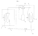
- FIG. 1 is a schematic view of a heat pump according to an embodiment as broadly described herein;
- FIG. 2 is an enlarged view of a section of an outdoor heat exchanger of the heat pump shown in FIG. 1 ;
- FIG. 3 is a graph of a heating operation duration with a respect to a ratio of hydrophilic coating and water repellent coating of the heat pump shown in FIGs. 1 and 2 ;
- FIG. 4 is a graph of a defrosting operation duration with respect to a ratio of hydrophilic coating and water repellent coating of the heat pump shown in FIGs. 1 and 2 ;
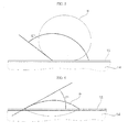
- FIG. 5 is an enlarged side view of condensation water generated on a water repellent coated fin of the heat pump shown in FIGs. 1 and 2 ;
- FIG. 6 is an enlarged side view of condensation water generated on a hydrophilic coated fin of the heat pump shown in FIGS. 1 and 2 .
- a heat pump as embodied and broadly described herein may include a compressor 2 for compressing a refrigerant, and an outdoor heat exchanger 4 for heat-exchanging a refrigerant with outdoor air.
- the outdoor heat exchanger 4 allows a refrigerant to be heat-exchanged with outdoor air flowing due to operation of an outdoor fan 5 to thus condense or evaporate the refrigerant.
- the heat pump may include an indoor heat exchanger 6 allowing a refrigerant to be heat-exchanged with indoor air, or heat-exchanged with a heating medium such as an anti-freeze solution, water, or the like.
- the heat pump may be configured as a heat pump type air-conditioner and/or a heat pump type hot water supply device.
- a heat pump type air-conditioner indoor air is heat-exchanged with the refrigerant in the indoor heat exchanger 6 and then discharged into an indoor area to change an indoor temperature.
- a heating medium such as water, an anti-freeze solution, or the like, may be heat-exchanged with a refrigerant in the indoor heat exchanger 6 so as to be used for supplying hot water.
- the indoor-heat exchanger 6 includes a refrigerant tube allowing a refrigerant to pass therethrough and a fin-tube heat exchanger including one or more fins coupled with the refrigerant tube, whereby indoor air is in contact with the fin-tube heat exchanger so as to be heat-exchanged with a refrigerant.
- the indoor heat-exchanger 6 heat-exchanges indoor air flowing due to operation of an indoor fan 7 with a refrigerant that passes through therein to condense or evaporate the refrigerant.
- the indoor heat exchanger 6 is configured as a dual-pipe heat exchanger, a plate type heat exchanger, or a shell-tube type heat exchanger including a first flow path allowing the refrigerant to pass therethrough and a second flow path allowing a heating medium to pass therethrough, in which the refrigerant in the first flow path and the heating medium in the second flow path are heat-exchanged with a heat transmission member interposed therebetween, and in this case, the heating medium, passing through the second flow path, is heat-exchanged with the refrigerant through the heat transmission member.
- the indoor heat exchanger 6 may be connected with a reservoir (or hot water tank) in which the heating medium is accommodated, through a heating medium circulation flow path, and as the heating medium flowing from the reservoir (or hot water tank) passes through the second flow path of the indoor heat exchanger 6, the refrigerant is evaporated or condensed.
- the heat pump includes an expansion mechanism 8 installed between the indoor heat exchanger 6 and the outdoor heat exchanger 4 to expand a refrigerant.
- the heat pump further includes a flow path switch 10 for allowing the refrigerant to circulate from the outdoor heat exchanger 4, to the expansion mechanism 8, and then to the indoor heat exchanger 6, or from the compressor 2, to the indoor heat exchanger 6, then to the expansion mechanism 8, and then to the outdoor heat exchanger 4.
- the flow path switch 10 may be one 4-way valve that changes a flow direction of the refrigerant, or a plurality of switching valves that change the flow direction of the refrigerant. In the following description, it is assumed that one 4-way valve is used to change the flow direction of the refrigerant.
- the heat pump may include an outdoor unit O including the compressor 2, the outdoor heat exchanger 4, the outdoor fan 5, the expansion mechanism 8, and the flow path switch 10, and an indoor unit I including the indoor heat exchanger 6 and the indoor fan 7.
- the heat pump may perform a cooling operation and a heating operation. In alternative embodiments, the heat pump may perform the cooling operation, the heating operation, and a defrosting operation, or may perform the heating operation and the defrosting operation.
- the cooling operation is performed to cool a heating medium or indoor air using the indoor heat exchanger 6.
- the refrigerant compressed in the compressor 2 flows to the outdoor heat exchanger 4, sequentially passes through the expansion mechanism 8 and the indoor heat exchanger 6, and then, is returned to the compressor 2.
- the heating operation is performed to heat the heating medium or indoor air.
- the refrigerant compressed in the compressor 2 flows to the indoor heat exchanger 6, sequentially passes through the expansion mechanism 8 and the outdoor heat exchanger 4, and then is returned to the compressor 2.
- the defrosting operation is performed to eliminate frost generated at the outdoor heat exchanger 4 by directing compressed refrigerant to the outdoor heat exchanger 4.
- the refrigerant compressed in the compressor 2 flows to the outdoor heat exchanger 4, sequentially passes through the expansion mechanism 8 and the indoor heat exchanger 6, and then is returned to the compressor 2.
- a portion of the compressed refrigerant may pass through a portion of the flow path of the outdoor heat exchanger 4 to partially defrost the outdoor heat exchanger 4, and the remaining compressed refrigerant may sequentially pass through the indoor heat exchanger 6 and the expansion mechanism 8, pass through the remaining portion of the flow path of the outdoor heat exchanger 4, and then, may be returned to the compressor 2.
- the defrosting operation When a defrosting condition is met while the heating operation is being performed, the defrosting operation is performed. Thereafter, when a defrosting complete condition is met, the operation may be returned to the heating operation again.
- the defrosting condition may include, for example, an accumulation of a predetermined amount of operation time of the heat pump in the heating operation, an outdoor temperature, a suction overheat degree, and the like, which triggers the need for defrosting setting conditions.
- the defrosting complete condition may include, for example, a predetermined amount of time during which the heat pump has been operated in the defrosting operation, the outdoor temperature, the suction overheat degree, and the like, which indicates that defrosting is complete and the defrosting operation may be terminated.
- the flow path switch 10 directs the refrigerant compressed in the compressor 2 to the outdoor heat exchanger 4, and when the defrosting condition is met, the flow path switch 10 directs the refrigerant compressed in the compressor 2 to the indoor heat exchanger 6, and thereafter, when the heat pump is returned to the heating operation, the flow path switch 10 directs the compressed refrigerant compressed in the compressor 2 to the outdoor heat exchanger 4.
- the outdoor heat exchanger 4 may be configured as a fin-tube heat exchanger including a refrigerant tube 12 allowing a refrigerant to pass therethrough and one or more fins 14 coupled to the refrigerant tube 12. Outdoor air is heat-exchanged with the refrigerant through the one or more fins 14 and the refrigerant rube 12. Both water repellent coating material 16 and hydrophilic coating material 18 may be coated on the fins 14 of the outdoor heat exchanger 4.
- the water repellent coating material 16 is coated on one surface of the fins 14 and the hydrophilic coating material 18 is coated on the other surface of the fins 14 (i.e., a surface opposite the surface on which the water repellent coating material is coated).
- frost growth on the surface of the fins 14 may be delayed and a heating operation duration, without the need for a defrosting operation, may be lengthened.
- frost melt during the defrosting operation may be more quickly accomplished, and a duration of the defrosting operation may be shortened.
- the fins 14 may be coated with both the hydrophilic coating material 18 and the water repellent coating material 16 such that frost growth may be delayed and any accumulated frost may be defrosted within a shortened amount of time.
- a duration of the heating operation may be affected as shown in FIG. 3 and a duration of the defrosting operation may be affected as shown in FIG. 4 .
- the area of the fins 14 coated with the water repellent coating material 16 may be larger than the area coated with the hydrophilic coating material 18. In certain embodiments, the area of the fins 14 coated with the water repellent coating material 16 may be greater 0.5 times and less than 0.6 times the area of the fins 14 that is exposed to/is in contact with air.
- the area of the fins 14 coated with the water repellent coating material 16 is less than 0.5 times the area that is in contact with air, a corresponding duration of the heating operation may be too short, and when the area of the fins 14 coated with the water repellent coating material 16 is greater 0.6 times the area in contact with air, the duration of the heating operation duration may be lengthened, but in this case, the duration of the defrosting operation duration would also be lengthened.
- the area of the fins 14 coated with the water repellent coating material 16 is greater than 0.5 times but less than 0.6 times the area in contact with air.
- Each of the fins 14 include a plate body 22 having two opposite faces thereof in contact with outdoor air and a collar 24 that protrudes in a cylindrical shape from the plate body 22 and coupled with the refrigerant tube 12.
- Both faces of the plate body 22 may form outdoor air contact surfaces, and one of the two faces may be coated with the water repellent coating material 16 and the other may be coated with the hydrophilic coating material 18.
- An inner circumferential surface A of the collar 24 may contact the refrigerant tube 12, and an outer circumferential face B of the collar 24 may make contact with outdoor air.
- the inner circumferential face A of the collar 24 may be coated with the hydrophilic coating material 18 and the outer circumferential face B of the collar 24 may be coated with the water repellent coating material 16.
- the two opposite faces C and D of the plate body 22 may include one face D that extends outward from and is perpendicular to the outer circumferential face B of the collar 24 and which may be coated with the water repellent coating material 16.
- the opposite face C of the of the plate body 22 may be coated with the hydrophilic coating material 18, and may extend from and be perpendicular to the inner circumferential face A of the collar 24.
- a plurality of fins 14 may be coupled to the refrigerant tube 12 along a length of the refrigerant tube 12, separated from each other by a predetermined interval.
- the collars 24 are coupled with the plurality of fins 14 and are arranged along the refrigerant tube 12 such that the collars 24 protrude in the same direction, and are arranged such that the water repellent coating material 16 and the hydrophilic coating material 18 may be positioned in order of water repellent coating material 16 ⁇ hydrophilic coating material 18 ⁇ water repellent coating material 16 ⁇ hydrophilic coating material 18 in a direction perpendicular to the flow of outdoor air.
- the hydrophilic coating material 18 coated on any one of the plurality of fins 14 is positioned to face the water repellent coating material 16 coated on any of the other of the plurality of fins 14, in particular, an adjacent fin 14, and condensation water between the fins 14 may be quickly discharged along the hydrophilic coating material 18.
- FIG. 5 is an enlarged side view of condensation water generated on a water repellent coated surface of a fin of a heat pump as embodied and broadly described herein
- FIG. 6 is an enlarged side view of condensation water generated on a hydrophilic coated surface of a fin of a heat pump as embodied and broadly described herein.
- the fins 14 of the outdoor heat exchanger 4 may be made of an aluminum material which may be relatively low-priced compared with a copper material.
- an aluminum material may include, for example, an aluminum alloy.
- the water repellent coating material 16 may be a coating material that meets the condition in which a contact angle E° of condensation water W generated on the surface of the water repellent coating material 16 is greater than about 90° and is less than about 150° and the hydrophilic coating material 18 may be a coating material that meets the condition in which a contact angle F° of condensation water W is greater than about 0° and is less than about 30°.
- An outdoor heat exchanger and a heat pump having the same are provided a heating operation duration may be lengthened and heating performance may be enhanced.
- any reference in this specification to "one embodiment,” “an embodiment,” “example embodiment,” etc. means that a particular feature, structure, or characteristic described in connection with the embodiment is included in at least one embodiment of the invention.
- the appearances of such phrases in various places in the specification are not necessarily all referring to the same embodiment.
Landscapes
- Engineering & Computer Science (AREA)
- Physics & Mathematics (AREA)
- Thermal Sciences (AREA)
- Mechanical Engineering (AREA)
- General Engineering & Computer Science (AREA)
- Geometry (AREA)
- Other Air-Conditioning Systems (AREA)
- Heat-Pump Type And Storage Water Heaters (AREA)
- Heat-Exchange Devices With Radiators And Conduit Assemblies (AREA)
Applications Claiming Priority (1)
| Application Number | Priority Date | Filing Date | Title |
|---|---|---|---|
| KR1020100115643A KR20120054321A (ko) | 2010-11-19 | 2010-11-19 | 히트 펌프 |
Publications (3)
| Publication Number | Publication Date |
|---|---|
| EP2455687A2 true EP2455687A2 (de) | 2012-05-23 |
| EP2455687A3 EP2455687A3 (de) | 2015-09-30 |
| EP2455687B1 EP2455687B1 (de) | 2017-08-30 |
Family
ID=45440097
Family Applications (1)
| Application Number | Title | Priority Date | Filing Date |
|---|---|---|---|
| EP11189705.4A Not-in-force EP2455687B1 (de) | 2010-11-19 | 2011-11-18 | Außenwärmetauscher und Wärmepumpe mit diesem Wärmetauscher |
Country Status (4)
| Country | Link |
|---|---|
| US (1) | US20120125030A1 (de) |
| EP (1) | EP2455687B1 (de) |
| KR (1) | KR20120054321A (de) |
| CN (1) | CN102538297B (de) |
Cited By (2)
| Publication number | Priority date | Publication date | Assignee | Title |
|---|---|---|---|---|
| EP2626654A3 (de) * | 2012-02-10 | 2015-01-14 | LG Electronics, Inc. | Wärmepumpe |
| EP3379192A4 (de) * | 2015-11-20 | 2019-07-17 | UACJ Corporation | Vorbeschichteten rippe und wärmetauscher |
Families Citing this family (9)
| Publication number | Priority date | Publication date | Assignee | Title |
|---|---|---|---|---|
| JP5932597B2 (ja) * | 2012-10-11 | 2016-06-08 | 三菱電機株式会社 | 熱交換器及びその製造方法、並びに該熱交換器を備えた空気調和機 |
| KR20140096706A (ko) * | 2013-01-29 | 2014-08-06 | 한라비스테온공조 주식회사 | 증발기 |
| US10107509B2 (en) * | 2014-11-21 | 2018-10-23 | Mitsubishi Electric Corporation | System and method for controlling an outdoor air conditioner |
| WO2017179399A1 (ja) * | 2016-04-15 | 2017-10-19 | 三菱電機株式会社 | 熱交換器 |
| JP6471824B2 (ja) * | 2017-03-31 | 2019-02-20 | ダイキン工業株式会社 | 熱交換器および空気調和装置 |
| JP2019016709A (ja) * | 2017-07-07 | 2019-01-31 | 富士通株式会社 | 冷却装置、排気浄化装置及び自動車 |
| CN114127503A (zh) * | 2019-07-20 | 2022-03-01 | 尼蓝宝股份有限公司 | 热交换器及其系统 |
| US20230121635A1 (en) * | 2021-10-14 | 2023-04-20 | Amulaire Thermal Technology, Inc. | Immersion heat dissipation structure having macroscopic fin structure and immersion heat dissipation structure having fin structure |
| WO2026079626A1 (ko) * | 2024-10-11 | 2026-04-16 | 삼성전자주식회사 | 열 교환기 및 이를 포함하는 냉장고 |
Family Cites Families (25)
| Publication number | Priority date | Publication date | Assignee | Title |
|---|---|---|---|---|
| US4434844A (en) * | 1981-05-15 | 1984-03-06 | Daikin Kogyo Co., Ltd. | Cross-fin coil type heat exchanger |
| JPS60117098A (ja) * | 1983-11-28 | 1985-06-24 | Furukawa Alum Co Ltd | 熱交換器のフイン用プレコ−トアルミ薄板 |
| JPS60205194A (ja) * | 1984-03-28 | 1985-10-16 | Tokai Kinzoku Kk | 熱交換器のフイン材 |
| JPS62235477A (ja) * | 1986-04-03 | 1987-10-15 | Showa Alum Corp | アルミニウムの親水性皮膜形成剤 |
| US4741393A (en) * | 1987-07-24 | 1988-05-03 | Jw Aluminum Company | Heat exchanger with coated fins |
| US5181558A (en) * | 1990-11-13 | 1993-01-26 | Matsushita Refrigeration Company | Heat exchanger |
| JP2689358B2 (ja) * | 1991-02-18 | 1997-12-10 | 株式会社ゼクセル | 熱交換器 |
| JPH04371796A (ja) * | 1991-06-19 | 1992-12-24 | Matsushita Refrig Co Ltd | 熱交換器 |
| JPH06117788A (ja) * | 1992-10-02 | 1994-04-28 | Matsushita Refrig Co Ltd | 熱交換器 |
| JPH06331293A (ja) * | 1993-05-24 | 1994-11-29 | Matsushita Refrig Co Ltd | フィンアンドチューブ型熱交換器 |
| JPH08152287A (ja) * | 1994-11-29 | 1996-06-11 | Sanyo Electric Co Ltd | 熱交換器 |
| DE19617437A1 (de) * | 1996-05-02 | 1997-11-06 | Hermann Muecher Gmbh | Elastomere Ringraumdichtung |
| JPH112497A (ja) * | 1997-06-13 | 1999-01-06 | Furukawa Electric Co Ltd:The | 熱交換器 |
| JP2000074588A (ja) * | 1998-08-31 | 2000-03-14 | Toshiba Corp | 空気調和機用フィンチューブ型熱交換器 |
| JP2001201288A (ja) * | 2000-01-18 | 2001-07-27 | Matsushita Refrig Co Ltd | 空気調和機のフィンアンドチューブ型熱交換器 |
| US6742370B2 (en) * | 2002-03-28 | 2004-06-01 | Carrier Corporation | High fin density coil design utilizing precoated fin stock |
| KR20040017768A (ko) * | 2002-08-23 | 2004-02-27 | 엘지전자 주식회사 | 열교환기의 응축수 배출장치 |
| JP3767611B2 (ja) * | 2004-04-28 | 2006-04-19 | ダイキン工業株式会社 | 吸着熱交換器 |
| JP2006046694A (ja) * | 2004-07-30 | 2006-02-16 | Daikin Ind Ltd | 冷凍装置 |
| CN101031771A (zh) * | 2004-09-30 | 2007-09-05 | 贝洱两合公司 | 热交换器及冷却增压空气的方法 |
| JP4506609B2 (ja) * | 2005-08-08 | 2010-07-21 | 三菱電機株式会社 | 空気調和機及び空気調和機の製造方法 |
| WO2007108386A1 (ja) * | 2006-03-23 | 2007-09-27 | Matsushita Electric Industrial Co., Ltd. | フィンチューブ型熱交換器、熱交換器用フィンおよびヒートポンプ装置 |
| JP2009235338A (ja) * | 2008-03-28 | 2009-10-15 | Mitsubishi Electric Corp | コーティング組成物、熱交換器、空気調和機 |
| JP2010065916A (ja) * | 2008-09-10 | 2010-03-25 | Hitachi Cable Ltd | 熱交換器及びその製造方法 |
| CN201575646U (zh) * | 2009-10-20 | 2010-09-08 | 珠海格力电器股份有限公司 | 换热器 |
-
2010
- 2010-11-19 KR KR1020100115643A patent/KR20120054321A/ko not_active Ceased
-
2011
- 2011-11-17 US US13/298,335 patent/US20120125030A1/en not_active Abandoned
- 2011-11-18 CN CN201110378687.9A patent/CN102538297B/zh not_active Expired - Fee Related
- 2011-11-18 EP EP11189705.4A patent/EP2455687B1/de not_active Not-in-force
Non-Patent Citations (1)
| Title |
|---|
| None |
Cited By (2)
| Publication number | Priority date | Publication date | Assignee | Title |
|---|---|---|---|---|
| EP2626654A3 (de) * | 2012-02-10 | 2015-01-14 | LG Electronics, Inc. | Wärmepumpe |
| EP3379192A4 (de) * | 2015-11-20 | 2019-07-17 | UACJ Corporation | Vorbeschichteten rippe und wärmetauscher |
Also Published As
| Publication number | Publication date |
|---|---|
| KR20120054321A (ko) | 2012-05-30 |
| EP2455687A3 (de) | 2015-09-30 |
| CN102538297A (zh) | 2012-07-04 |
| US20120125030A1 (en) | 2012-05-24 |
| CN102538297B (zh) | 2014-12-03 |
| EP2455687B1 (de) | 2017-08-30 |
Similar Documents
| Publication | Publication Date | Title |
|---|---|---|
| EP2455687A2 (de) | Außenwärmetauscher und Wärmepumpe mit diesem Wärmetauscher | |
| CN109154460B (zh) | 层叠型集管、热交换器和空调装置 | |
| US20150107286A1 (en) | Heat pump | |
| US20180100659A1 (en) | Heat exchanger and air-conditioning apparatus | |
| US20130284416A1 (en) | Heat exchanger and air conditioner | |
| EP2626654A2 (de) | Wärmepumpe | |
| CN205425529U (zh) | 翅片管式热交换器以及具备它的制冷循环装置 | |
| US20200217588A1 (en) | Heat exchanger and refrigeration cycle apparatus | |
| JP6701371B2 (ja) | 熱交換器及び冷凍サイクル装置 | |
| JP6847229B2 (ja) | 熱交換器、及び冷凍サイクル装置 | |
| CN110741216B (zh) | 热交换器、制冷循环装置及空调机 | |
| JP7112053B2 (ja) | 熱交換器及びそれを用いた冷凍サイクル装置 | |
| CN114641663A (zh) | 热交换器及制冷循环装置 | |
| KR20150010826A (ko) | 공기조화기 및 이중관 열교환기 | |
| JPWO2017017789A1 (ja) | 熱交換器及び冷凍サイクル装置 | |
| JP5627635B2 (ja) | 空気調和機 | |
| US20210108864A1 (en) | Heat exchanger, heat exchanger unit, and refrigeration cycle apparatus | |
| JP6692495B2 (ja) | 熱交換器及び冷凍サイクル装置 | |
| JP2004271113A (ja) | 熱交換器 | |
| JP2006046695A (ja) | 冷凍装置 | |
| CN107850358B (zh) | 热交换器及制冷循环装置 | |
| WO2018185824A1 (ja) | 熱交換器および冷凍サイクル装置 | |
| JPH10274493A (ja) | 熱交換器 | |
| JP5864030B1 (ja) | 熱交換器、及び、この熱交換器を備えた冷凍サイクル装置 | |
| WO2012098915A1 (ja) | 熱交換器および空気調和機 |
Legal Events
| Date | Code | Title | Description |
|---|---|---|---|
| PUAI | Public reference made under article 153(3) epc to a published international application that has entered the european phase |
Free format text: ORIGINAL CODE: 0009012 |
|
| 17P | Request for examination filed |
Effective date: 20111214 |
|
| AK | Designated contracting states |
Kind code of ref document: A2 Designated state(s): AL AT BE BG CH CY CZ DE DK EE ES FI FR GB GR HR HU IE IS IT LI LT LU LV MC MK MT NL NO PL PT RO RS SE SI SK SM TR |
|
| AX | Request for extension of the european patent |
Extension state: BA ME |
|
| PUAL | Search report despatched |
Free format text: ORIGINAL CODE: 0009013 |
|
| AK | Designated contracting states |
Kind code of ref document: A3 Designated state(s): AL AT BE BG CH CY CZ DE DK EE ES FI FR GB GR HR HU IE IS IT LI LT LU LV MC MK MT NL NO PL PT RO RS SE SI SK SM TR |
|
| AX | Request for extension of the european patent |
Extension state: BA ME |
|
| RIC1 | Information provided on ipc code assigned before grant |
Ipc: F25B 39/00 20060101AFI20150824BHEP |
|
| RBV | Designated contracting states (corrected) |
Designated state(s): AL AT BE BG CH CY CZ DE DK EE ES FI FR GB GR HR HU IE IS IT LI LT LU LV MC MK MT NL NO PL PT RO RS SE SI SK SM TR |
|
| GRAP | Despatch of communication of intention to grant a patent |
Free format text: ORIGINAL CODE: EPIDOSNIGR1 |
|
| INTG | Intention to grant announced |
Effective date: 20170315 |
|
| GRAS | Grant fee paid |
Free format text: ORIGINAL CODE: EPIDOSNIGR3 |
|
| GRAA | (expected) grant |
Free format text: ORIGINAL CODE: 0009210 |
|
| AK | Designated contracting states |
Kind code of ref document: B1 Designated state(s): AL AT BE BG CH CY CZ DE DK EE ES FI FR GB GR HR HU IE IS IT LI LT LU LV MC MK MT NL NO PL PT RO RS SE SI SK SM TR |
|
| REG | Reference to a national code |
Ref country code: GB Ref legal event code: FG4D |
|
| REG | Reference to a national code |
Ref country code: CH Ref legal event code: EP |
|
| REG | Reference to a national code |
Ref country code: AT Ref legal event code: REF Ref document number: 923943 Country of ref document: AT Kind code of ref document: T Effective date: 20170915 |
|
| REG | Reference to a national code |
Ref country code: IE Ref legal event code: FG4D |
|
| REG | Reference to a national code |
Ref country code: DE Ref legal event code: R096 Ref document number: 602011041037 Country of ref document: DE |
|
| REG | Reference to a national code |
Ref country code: FR Ref legal event code: PLFP Year of fee payment: 7 |
|
| REG | Reference to a national code |
Ref country code: NL Ref legal event code: MP Effective date: 20170830 |
|
| REG | Reference to a national code |
Ref country code: LT Ref legal event code: MG4D |
|
| REG | Reference to a national code |
Ref country code: AT Ref legal event code: MK05 Ref document number: 923943 Country of ref document: AT Kind code of ref document: T Effective date: 20170830 |
|
| PG25 | Lapsed in a contracting state [announced via postgrant information from national office to epo] |
Ref country code: FI Free format text: LAPSE BECAUSE OF FAILURE TO SUBMIT A TRANSLATION OF THE DESCRIPTION OR TO PAY THE FEE WITHIN THE PRESCRIBED TIME-LIMIT Effective date: 20170830 Ref country code: AT Free format text: LAPSE BECAUSE OF FAILURE TO SUBMIT A TRANSLATION OF THE DESCRIPTION OR TO PAY THE FEE WITHIN THE PRESCRIBED TIME-LIMIT Effective date: 20170830 Ref country code: LT Free format text: LAPSE BECAUSE OF FAILURE TO SUBMIT A TRANSLATION OF THE DESCRIPTION OR TO PAY THE FEE WITHIN THE PRESCRIBED TIME-LIMIT Effective date: 20170830 Ref country code: SE Free format text: LAPSE BECAUSE OF FAILURE TO SUBMIT A TRANSLATION OF THE DESCRIPTION OR TO PAY THE FEE WITHIN THE PRESCRIBED TIME-LIMIT Effective date: 20170830 Ref country code: HR Free format text: LAPSE BECAUSE OF FAILURE TO SUBMIT A TRANSLATION OF THE DESCRIPTION OR TO PAY THE FEE WITHIN THE PRESCRIBED TIME-LIMIT Effective date: 20170830 Ref country code: NO Free format text: LAPSE BECAUSE OF FAILURE TO SUBMIT A TRANSLATION OF THE DESCRIPTION OR TO PAY THE FEE WITHIN THE PRESCRIBED TIME-LIMIT Effective date: 20171130 |
|
| PG25 | Lapsed in a contracting state [announced via postgrant information from national office to epo] |
Ref country code: BG Free format text: LAPSE BECAUSE OF FAILURE TO SUBMIT A TRANSLATION OF THE DESCRIPTION OR TO PAY THE FEE WITHIN THE PRESCRIBED TIME-LIMIT Effective date: 20171130 Ref country code: GR Free format text: LAPSE BECAUSE OF FAILURE TO SUBMIT A TRANSLATION OF THE DESCRIPTION OR TO PAY THE FEE WITHIN THE PRESCRIBED TIME-LIMIT Effective date: 20171201 Ref country code: ES Free format text: LAPSE BECAUSE OF FAILURE TO SUBMIT A TRANSLATION OF THE DESCRIPTION OR TO PAY THE FEE WITHIN THE PRESCRIBED TIME-LIMIT Effective date: 20170830 Ref country code: LV Free format text: LAPSE BECAUSE OF FAILURE TO SUBMIT A TRANSLATION OF THE DESCRIPTION OR TO PAY THE FEE WITHIN THE PRESCRIBED TIME-LIMIT Effective date: 20170830 Ref country code: RS Free format text: LAPSE BECAUSE OF FAILURE TO SUBMIT A TRANSLATION OF THE DESCRIPTION OR TO PAY THE FEE WITHIN THE PRESCRIBED TIME-LIMIT Effective date: 20170830 Ref country code: IS Free format text: LAPSE BECAUSE OF FAILURE TO SUBMIT A TRANSLATION OF THE DESCRIPTION OR TO PAY THE FEE WITHIN THE PRESCRIBED TIME-LIMIT Effective date: 20171230 |
|
| PG25 | Lapsed in a contracting state [announced via postgrant information from national office to epo] |
Ref country code: NL Free format text: LAPSE BECAUSE OF FAILURE TO SUBMIT A TRANSLATION OF THE DESCRIPTION OR TO PAY THE FEE WITHIN THE PRESCRIBED TIME-LIMIT Effective date: 20170830 |
|
| PG25 | Lapsed in a contracting state [announced via postgrant information from national office to epo] |
Ref country code: DK Free format text: LAPSE BECAUSE OF FAILURE TO SUBMIT A TRANSLATION OF THE DESCRIPTION OR TO PAY THE FEE WITHIN THE PRESCRIBED TIME-LIMIT Effective date: 20170830 Ref country code: PL Free format text: LAPSE BECAUSE OF FAILURE TO SUBMIT A TRANSLATION OF THE DESCRIPTION OR TO PAY THE FEE WITHIN THE PRESCRIBED TIME-LIMIT Effective date: 20170830 Ref country code: RO Free format text: LAPSE BECAUSE OF FAILURE TO SUBMIT A TRANSLATION OF THE DESCRIPTION OR TO PAY THE FEE WITHIN THE PRESCRIBED TIME-LIMIT Effective date: 20170830 Ref country code: CZ Free format text: LAPSE BECAUSE OF FAILURE TO SUBMIT A TRANSLATION OF THE DESCRIPTION OR TO PAY THE FEE WITHIN THE PRESCRIBED TIME-LIMIT Effective date: 20170830 |
|
| PG25 | Lapsed in a contracting state [announced via postgrant information from national office to epo] |
Ref country code: SM Free format text: LAPSE BECAUSE OF FAILURE TO SUBMIT A TRANSLATION OF THE DESCRIPTION OR TO PAY THE FEE WITHIN THE PRESCRIBED TIME-LIMIT Effective date: 20170830 Ref country code: SK Free format text: LAPSE BECAUSE OF FAILURE TO SUBMIT A TRANSLATION OF THE DESCRIPTION OR TO PAY THE FEE WITHIN THE PRESCRIBED TIME-LIMIT Effective date: 20170830 Ref country code: IT Free format text: LAPSE BECAUSE OF FAILURE TO SUBMIT A TRANSLATION OF THE DESCRIPTION OR TO PAY THE FEE WITHIN THE PRESCRIBED TIME-LIMIT Effective date: 20170830 Ref country code: EE Free format text: LAPSE BECAUSE OF FAILURE TO SUBMIT A TRANSLATION OF THE DESCRIPTION OR TO PAY THE FEE WITHIN THE PRESCRIBED TIME-LIMIT Effective date: 20170830 |
|
| REG | Reference to a national code |
Ref country code: DE Ref legal event code: R097 Ref document number: 602011041037 Country of ref document: DE |
|
| REG | Reference to a national code |
Ref country code: DE Ref legal event code: R119 Ref document number: 602011041037 Country of ref document: DE |
|
| PG25 | Lapsed in a contracting state [announced via postgrant information from national office to epo] |
Ref country code: MC Free format text: LAPSE BECAUSE OF FAILURE TO SUBMIT A TRANSLATION OF THE DESCRIPTION OR TO PAY THE FEE WITHIN THE PRESCRIBED TIME-LIMIT Effective date: 20170830 |
|
| PLBE | No opposition filed within time limit |
Free format text: ORIGINAL CODE: 0009261 |
|
| STAA | Information on the status of an ep patent application or granted ep patent |
Free format text: STATUS: NO OPPOSITION FILED WITHIN TIME LIMIT |
|
| GBPC | Gb: european patent ceased through non-payment of renewal fee |
Effective date: 20171130 |
|
| PG25 | Lapsed in a contracting state [announced via postgrant information from national office to epo] |
Ref country code: CH Free format text: LAPSE BECAUSE OF NON-PAYMENT OF DUE FEES Effective date: 20171130 Ref country code: LI Free format text: LAPSE BECAUSE OF NON-PAYMENT OF DUE FEES Effective date: 20171130 |
|
| 26N | No opposition filed |
Effective date: 20180531 |
|
| PG25 | Lapsed in a contracting state [announced via postgrant information from national office to epo] |
Ref country code: LU Free format text: LAPSE BECAUSE OF NON-PAYMENT OF DUE FEES Effective date: 20171118 Ref country code: SI Free format text: LAPSE BECAUSE OF FAILURE TO SUBMIT A TRANSLATION OF THE DESCRIPTION OR TO PAY THE FEE WITHIN THE PRESCRIBED TIME-LIMIT Effective date: 20170830 |
|
| REG | Reference to a national code |
Ref country code: BE Ref legal event code: MM Effective date: 20171130 |
|
| REG | Reference to a national code |
Ref country code: IE Ref legal event code: MM4A |
|
| PG25 | Lapsed in a contracting state [announced via postgrant information from national office to epo] |
Ref country code: MT Free format text: LAPSE BECAUSE OF NON-PAYMENT OF DUE FEES Effective date: 20171118 |
|
| REG | Reference to a national code |
Ref country code: FR Ref legal event code: PLFP Year of fee payment: 8 |
|
| PG25 | Lapsed in a contracting state [announced via postgrant information from national office to epo] |
Ref country code: DE Free format text: LAPSE BECAUSE OF NON-PAYMENT OF DUE FEES Effective date: 20180602 Ref country code: IE Free format text: LAPSE BECAUSE OF NON-PAYMENT OF DUE FEES Effective date: 20171118 |
|
| PG25 | Lapsed in a contracting state [announced via postgrant information from national office to epo] |
Ref country code: BE Free format text: LAPSE BECAUSE OF NON-PAYMENT OF DUE FEES Effective date: 20171130 Ref country code: GB Free format text: LAPSE BECAUSE OF NON-PAYMENT OF DUE FEES Effective date: 20171130 |
|
| PG25 | Lapsed in a contracting state [announced via postgrant information from national office to epo] |
Ref country code: HU Free format text: LAPSE BECAUSE OF FAILURE TO SUBMIT A TRANSLATION OF THE DESCRIPTION OR TO PAY THE FEE WITHIN THE PRESCRIBED TIME-LIMIT; INVALID AB INITIO Effective date: 20111118 |
|
| PG25 | Lapsed in a contracting state [announced via postgrant information from national office to epo] |
Ref country code: CY Free format text: LAPSE BECAUSE OF NON-PAYMENT OF DUE FEES Effective date: 20170830 |
|
| PG25 | Lapsed in a contracting state [announced via postgrant information from national office to epo] |
Ref country code: MK Free format text: LAPSE BECAUSE OF FAILURE TO SUBMIT A TRANSLATION OF THE DESCRIPTION OR TO PAY THE FEE WITHIN THE PRESCRIBED TIME-LIMIT Effective date: 20170830 |
|
| PG25 | Lapsed in a contracting state [announced via postgrant information from national office to epo] |
Ref country code: TR Free format text: LAPSE BECAUSE OF FAILURE TO SUBMIT A TRANSLATION OF THE DESCRIPTION OR TO PAY THE FEE WITHIN THE PRESCRIBED TIME-LIMIT Effective date: 20170830 |
|
| PG25 | Lapsed in a contracting state [announced via postgrant information from national office to epo] |
Ref country code: PT Free format text: LAPSE BECAUSE OF FAILURE TO SUBMIT A TRANSLATION OF THE DESCRIPTION OR TO PAY THE FEE WITHIN THE PRESCRIBED TIME-LIMIT Effective date: 20170830 |
|
| PG25 | Lapsed in a contracting state [announced via postgrant information from national office to epo] |
Ref country code: AL Free format text: LAPSE BECAUSE OF FAILURE TO SUBMIT A TRANSLATION OF THE DESCRIPTION OR TO PAY THE FEE WITHIN THE PRESCRIBED TIME-LIMIT Effective date: 20170830 |
|
| PGFP | Annual fee paid to national office [announced via postgrant information from national office to epo] |
Ref country code: FR Payment date: 20221005 Year of fee payment: 12 |
|
| PG25 | Lapsed in a contracting state [announced via postgrant information from national office to epo] |
Ref country code: FR Free format text: LAPSE BECAUSE OF NON-PAYMENT OF DUE FEES Effective date: 20231130 |
|
| PG25 | Lapsed in a contracting state [announced via postgrant information from national office to epo] |
Ref country code: FR Free format text: LAPSE BECAUSE OF NON-PAYMENT OF DUE FEES Effective date: 20231130 |