EP2458301A2 - Dispositif d'agencement d'au moins un module solaire dans un sous-sol - Google Patents
Dispositif d'agencement d'au moins un module solaire dans un sous-sol Download PDFInfo
- Publication number
- EP2458301A2 EP2458301A2 EP11006460A EP11006460A EP2458301A2 EP 2458301 A2 EP2458301 A2 EP 2458301A2 EP 11006460 A EP11006460 A EP 11006460A EP 11006460 A EP11006460 A EP 11006460A EP 2458301 A2 EP2458301 A2 EP 2458301A2
- Authority
- EP
- European Patent Office
- Prior art keywords
- base unit
- latching
- solar module
- support element
- spacer
- Prior art date
- Legal status (The legal status is an assumption and is not a legal conclusion. Google has not performed a legal analysis and makes no representation as to the accuracy of the status listed.)
- Granted
Links
Images




Classifications
-
- H—ELECTRICITY
- H02—GENERATION; CONVERSION OR DISTRIBUTION OF ELECTRIC POWER
- H02S—GENERATION OF ELECTRIC POWER BY CONVERSION OF INFRARED RADIATION, VISIBLE LIGHT OR ULTRAVIOLET LIGHT, e.g. USING PHOTOVOLTAIC [PV] MODULES
- H02S20/00—Supporting structures for PV modules
-
- F—MECHANICAL ENGINEERING; LIGHTING; HEATING; WEAPONS; BLASTING
- F24—HEATING; RANGES; VENTILATING
- F24S—SOLAR HEAT COLLECTORS; SOLAR HEAT SYSTEMS
- F24S25/00—Arrangement of stationary mountings or supports for solar heat collector modules
- F24S25/10—Arrangement of stationary mountings or supports for solar heat collector modules extending in directions away from a supporting surface
- F24S25/13—Profile arrangements, e.g. trusses
-
- F—MECHANICAL ENGINEERING; LIGHTING; HEATING; WEAPONS; BLASTING
- F24—HEATING; RANGES; VENTILATING
- F24S—SOLAR HEAT COLLECTORS; SOLAR HEAT SYSTEMS
- F24S25/00—Arrangement of stationary mountings or supports for solar heat collector modules
- F24S25/40—Arrangement of stationary mountings or supports for solar heat collector modules using plate-like mounting elements, e.g. profiled or corrugated plates; Plate-like module frames
-
- F—MECHANICAL ENGINEERING; LIGHTING; HEATING; WEAPONS; BLASTING
- F24—HEATING; RANGES; VENTILATING
- F24S—SOLAR HEAT COLLECTORS; SOLAR HEAT SYSTEMS
- F24S25/00—Arrangement of stationary mountings or supports for solar heat collector modules
- F24S25/60—Fixation means, e.g. fasteners, specially adapted for supporting solar heat collector modules
- F24S25/63—Fixation means, e.g. fasteners, specially adapted for supporting solar heat collector modules for fixing modules or their peripheral frames to supporting elements
- F24S25/632—Side connectors; Base connectors
-
- F—MECHANICAL ENGINEERING; LIGHTING; HEATING; WEAPONS; BLASTING
- F24—HEATING; RANGES; VENTILATING
- F24S—SOLAR HEAT COLLECTORS; SOLAR HEAT SYSTEMS
- F24S25/00—Arrangement of stationary mountings or supports for solar heat collector modules
- F24S25/70—Arrangement of stationary mountings or supports for solar heat collector modules with means for adjusting the final position or orientation of supporting elements in relation to each other or to a mounting surface; with means for compensating mounting tolerances
-
- F—MECHANICAL ENGINEERING; LIGHTING; HEATING; WEAPONS; BLASTING
- F24—HEATING; RANGES; VENTILATING
- F24S—SOLAR HEAT COLLECTORS; SOLAR HEAT SYSTEMS
- F24S30/00—Arrangements for moving or orienting solar heat collector modules
- F24S30/40—Arrangements for moving or orienting solar heat collector modules for rotary movement
- F24S30/42—Arrangements for moving or orienting solar heat collector modules for rotary movement with only one rotation axis
- F24S30/425—Horizontal axis
-
- F—MECHANICAL ENGINEERING; LIGHTING; HEATING; WEAPONS; BLASTING
- F24—HEATING; RANGES; VENTILATING
- F24S—SOLAR HEAT COLLECTORS; SOLAR HEAT SYSTEMS
- F24S25/00—Arrangement of stationary mountings or supports for solar heat collector modules
- F24S2025/01—Special support components; Methods of use
- F24S2025/012—Foldable support elements
-
- F—MECHANICAL ENGINEERING; LIGHTING; HEATING; WEAPONS; BLASTING
- F24—HEATING; RANGES; VENTILATING
- F24S—SOLAR HEAT COLLECTORS; SOLAR HEAT SYSTEMS
- F24S25/00—Arrangement of stationary mountings or supports for solar heat collector modules
- F24S25/60—Fixation means, e.g. fasteners, specially adapted for supporting solar heat collector modules
- F24S2025/6004—Fixation means, e.g. fasteners, specially adapted for supporting solar heat collector modules by clipping, e.g. by using snap connectors
-
- F—MECHANICAL ENGINEERING; LIGHTING; HEATING; WEAPONS; BLASTING
- F24—HEATING; RANGES; VENTILATING
- F24S—SOLAR HEAT COLLECTORS; SOLAR HEAT SYSTEMS
- F24S25/00—Arrangement of stationary mountings or supports for solar heat collector modules
- F24S2025/80—Special profiles
- F24S2025/804—U-, C- or O-shaped; Hat profiles
-
- Y—GENERAL TAGGING OF NEW TECHNOLOGICAL DEVELOPMENTS; GENERAL TAGGING OF CROSS-SECTIONAL TECHNOLOGIES SPANNING OVER SEVERAL SECTIONS OF THE IPC; TECHNICAL SUBJECTS COVERED BY FORMER USPC CROSS-REFERENCE ART COLLECTIONS [XRACs] AND DIGESTS
- Y02—TECHNOLOGIES OR APPLICATIONS FOR MITIGATION OR ADAPTATION AGAINST CLIMATE CHANGE
- Y02E—REDUCTION OF GREENHOUSE GAS [GHG] EMISSIONS, RELATED TO ENERGY GENERATION, TRANSMISSION OR DISTRIBUTION
- Y02E10/00—Energy generation through renewable energy sources
- Y02E10/40—Solar thermal energy, e.g. solar towers
- Y02E10/47—Mountings or tracking
-
- Y—GENERAL TAGGING OF NEW TECHNOLOGICAL DEVELOPMENTS; GENERAL TAGGING OF CROSS-SECTIONAL TECHNOLOGIES SPANNING OVER SEVERAL SECTIONS OF THE IPC; TECHNICAL SUBJECTS COVERED BY FORMER USPC CROSS-REFERENCE ART COLLECTIONS [XRACs] AND DIGESTS
- Y02—TECHNOLOGIES OR APPLICATIONS FOR MITIGATION OR ADAPTATION AGAINST CLIMATE CHANGE
- Y02E—REDUCTION OF GREENHOUSE GAS [GHG] EMISSIONS, RELATED TO ENERGY GENERATION, TRANSMISSION OR DISTRIBUTION
- Y02E10/00—Energy generation through renewable energy sources
- Y02E10/50—Photovoltaic [PV] energy
Definitions
- the invention relates to a device for arranging at least one solar module on a substrate, comprising at least one base unit, via which the device is connectable to the ground, at least one connectable to the base unit holding unit, via which the device is connectable to the solar module and the at least one Carrying member and an adjusting mechanism comprises, wherein the position of the support member is adjustable relative to the base unit by means of the adjusting mechanism.
- the invention relates to a solar system with at least one solar module.
- a stand for rectangular solar modules with which a solar module can be mounted inclined to a flat roof.
- the stand comprises a horizontal support, a post rising from the horizontal support and an inclined cross-beam connecting the post and the support to which the solar module can be fastened.
- the position of the traverse is adjustable relative to the wagerechten carrier in order to adjust the inclination angle of the traverse or arranged thereon a solar module can.
- the object of the invention is to provide a novel device for arranging at least one solar module on a substrate, which can be arranged with the least possible assembly effort by a layman on the ground.
- a device of the type mentioned above in that it comprises a latching mechanism, via which the holding unit can be releasably secured to the base unit.
- the holding unit can be connected to the base unit without the use of tools and thus with very little installation effort. It is only a force on the holding unit and / or the base unit required to bring about a desired locking of parts of the locking mechanism.
- This simple connectivity of the holding unit and the base unit makes it possible, in particular, for the device to be brought to a place of use in the form of a kit and to be placed there in a simple manner. There are no time-consuming assembly work such as at DE 20 2009 007 517 U1 necessary, which would have to be made in advance off the site.
- any horizontally or inclined surface arranged such as a roof or the ground floor, into consideration.
- the latching mechanism is formed by a latchable with the base unit latching element of the holding unit and the base unit, wherein the position of the support unit is adjustable relative to the latching element by means of the adjusting mechanism.
- the latter also causes the adjustability of the position of the support element relative to the base unit.
- the locking element is elongated and has at its opposite ends in the axial direction in each case a latching projection which can engage in correspondingly arranged on the base unit latching openings.
- the locking mechanism is formed in the simplest manner, without additional components are needed.
- the latching projections are preferably formed integrally with the latching element.
- a further advantageous embodiment of the invention provides that at least one detent opening has a snap element, which releasably engages behind the corresponding latching projection when the detent element is disposed on the base unit as intended.
- the snap mechanism formed thereby can be operated in a simple manner for releasing the detent, if the disassembly of the device is intended.
- the simple assembly and disassembly of the device this is particularly well suited for mobile and temporary use in different places.
- the base unit is formed in cross-section substantially U-shaped and has two legs and a web connecting them.
- the U-shaped configuration of the base unit significantly increases its stiffness.
- the base unit is thereby formed to a certain extent trough-shaped and can be filled at the site, for example, with bulk material, whereby the device is given a sufficient grip on a substrate, without it being necessary to connect the base unit via other fastening means to the ground. This favors in particular the outdoor use of the device according to the invention.
- the detent openings are arranged in the legs adjacent to the web and corresponds to the width of the web extending between the legs of the length of the locking element minus the locking projections.
- the locking element is intended to be arranged between the legs.
- the latching openings are arranged in a region on the legs, which has the highest stability through its connection to the web, so that the connection between the latching element and base unit is very durable, in particular because the latching connection is not deformed by the respective Schenkel can solve.
- the support member and the locking element are pivotally connected to each other about a pivot axis.
- the pivot axis is aligned with the arrangement of the holding unit on the base unit in a parallel and spaced from the longitudinal extension of the web and the legs.
- the support member and the latching element are each connected to one another at their opposite end areas of the pivot axis via a spacer.
- the spacer at different positions with the locking element and / or the support member is connectable.
- the spacer can be connected to the latching element and / or the carrying element at different positions, preferably along the longitudinal extension of the latching element and / or the carrying element.
- the spacer can be connected only at a certain position with the locking element and the support member, but its length is variable.
- the spacer is also part of the adjustment mechanism of the device.
- the support element, the latching element and / or the spacer in cross-section are substantially U-shaped and have or the support member, the latching element and / or the spacer each have two legs, which are interconnected via a web ,
- these components of the device have a high dimensional stability, which serves to create a very robust device.
- the legs in the end region of the support element and / or the latching element on a plurality of longitudinally extending connection openings, via which the support member and / or latching element by means of a bolt or screw connection to the spacer can be connected or is ,
- This allows the connection of the spacer with the locking element and / or the support member at different positions in order to fix the relative position between locking element and support member can.
- no special tool is required for connecting the spacer with the locking element and / or the support element. It is also possible that the spacer already before setting up the device on her each place of use is connected to the support member and / or the locking element, which emphasizes the kit character of the device according to the invention.
- means for fastening the solar module to the support unit are arranged on the support element. These may be formed in any suitable manner.
- the holding unit comprises a support member and a spacer
- support member and spacers are each connected at one end and at the other end the locking mechanism forming hook elements, which positively and non-positively into the base unit intervention.
- the hook member formed ends of the support member and the spacer are shaped like ordinary hooks and have sufficient bend to grip behind openings in the base unit.
- the attachment of the support element or the spacer to the base unit is effected by a rotation of the support element or of the spacer, which follows the bending of the hook element.
- the hook element prefferably has grooves or recesses into which a corresponding element, for example a projection or an opening edge, of the base unit can engage. This additionally avoids accidental slipping out of the hook from the opening.
- the hook elements each have two mutually parallel hooks. Thus, a simpler alignment and attachment of the hook element to the base unit is possible. If carrying element and spacers are formed from a U-profile, the hooks may each be formed on a leg of the U-profile.
- the base unit is formed in cross-section substantially U-shaped and has two legs, each having the hook elements corresponding engagement openings.
- the hooks of the hook elements can be shaped into these openings on the base unit. and intervene forcefully. By performed during insertion of the hooks in the openings rotational movement of the hook is hooked behind the opening so that it can not be removed from the opening after the connection of the opposite ends of support member and spacer.
- this positioning element can be a projection projecting beyond the boundary of the spacer (or alternatively also of the carrying element) which, for example in the case of a spacer formed from a U-profile, is a connecting leg protruding beyond the side legs.
- a slot is introduced into the profile through which the projection can engage.
- a plurality of slots are introduced in the support element (or the spacer) so that the support element can assume different angular positions relative to the base unit. If support element and spacer are both made of a U-profile, their end portions may be formed so that the end portion of the one can be positively received from the inside of the other.
- support element and spacers are screwed together after the pre-positioning described. If support element and spacers as described above are U-shaped so that one can engage positively in the other, it is possible that the screw (especially easy by prefabricated through holes) laterally engages through the two legs of the U-profiles and thus can be easily tightened from the side. Due to the lateral arrangement of the screw, the fitter has a good view of the screw connection.
- the invention provides that a fastening element pointing in the direction of the solar module is arranged on the support element, which is engageable in a form-fitting manner in a corresponding engagement of the solar module.
- a fastening element pointing in the direction of the solar module is arranged on the support element, which is engageable in a form-fitting manner in a corresponding engagement of the solar module.
- the fastener to the support member screwed.
- the fastening element arranged on the carrying element can be designed such that it is hook-shaped at one end region and at the opposite end region in the manner of a rail which has elongated holes. This makes it possible to hook the hook-shaped end portion into engagement of the solar module.
- This engagement on the back of the solar module may be, for example, a projection, undercut, slot, slot or the like.
- the rail-shaped end region of the fastening element can be designed such that it carries a slot which corresponds to a slot located on the support element.
- the slots can then be positioned in different positions to each other, so that different sized solar modules can be mounted or a different position of the solar module on the support member is possible.
- the solar module is firmly connected to the support member.
- a cross member may be arranged, which gives the overall device a greater lateral stability and ensures a uniform inclination of both spacers.
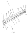
- FIG. 1 shows a perspective view of the holding unit 1 of an embodiment of the device 24 according to the invention, wherein the holding unit 1 is in its transport position. From this transport position, the holding unit 1 can be converted into its operating position, as in FIG. 2 is shown.
- the support unit 1 comprises a support element 2 and a latching element 3.
- the support element 2 is connectable to a solar module, not shown, to carry the latter in a desired manner.
- the operation of the locking element 3 is from the FIGS. 4 to 8 clear.
- the support member 2 and the locking element 3 are elongated and formed in cross-section substantially U-shaped. They each have two legs 5 and 6 or 7 and 8, which are connected to each other via a web 9 and 10 respectively.
- the support member 2 and the locking element 3 are pivotally connected to each other at the end shown on the left about a pivot axis S. For this purpose, 5 to 8 openings are introduced in the legs through which a bolt is guided, which is fixed by snap rings on the locking element 3 and the support member 2.
- the support element 2 further comprises means for attaching a solar module to the holding unit 1 in the form of elongated holes 11 and 12.
- the holding unit 1 further comprises a spacer 13, which is also formed in cross section also substantially U-shaped.
- the spacer 13 is connected via a bolt connection 14 with the support member 2.
- the support element 2 and the latching element 3 have at the respective ends facing the pivot axis S opposite, shown on the right end portions a plurality of the legs 5 and 6 or 7 and 8 in the longitudinal direction extending connecting openings 15.
- the support member 2 is connected by means of a bolt connection 14 with the spacer 13.
- the bolt connection 14 comprises a bolt 16, which is guided through connection openings 15 on the legs 5 and 6 and correspondingly in the legs of the spacer 13, and which is secured to the support element 2 via snap rings 17.
- connection openings 15 on the support element 2 and the latching element 3 it is possible for the spacer 13 to be connected at different positions to the latching element 3 and the support element 2 in order to fix a specific relative position between the support element 2 and the latching element 3 ,
- the latching element 3 has at its opposite ends in the axial direction in each case a latching projection 18, of which in FIG. 1 only the arranged at the left end of the locking element 18 can be seen.
- the latching projections 18 form part of the latching mechanism.
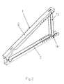
- FIG. 2 is a perspective view of in FIG. 1 shown holding unit 1 in its insertion position, in which the support member 2 is arranged at a desired angle to the locking element 3. This relative position of locking element 3 and supporting element 2 is fixed on the spacer 13, which according to FIG. 2 is also connected to the locking element 3 via a bolt connection 14.
- FIG. 3 shows a perspective view of the base unit 4 of an embodiment of the inventive device 24.
- the base unit 4 is formed in cross-section substantially U-shaped and has two legs 19 and 20 and a web 21 connecting them.
- the base unit 4 comprises four latching openings 22, which are arranged in the legs 19 and 20 adjacent to the web 21. To those in the FIGS. 1 and 2 shown retaining unit 1 to connect to the base unit 4, corresponds to the extending between the legs 19 and 20 width of the web 21 of the length of the locking element 3 minus the locking projections 18.
- the locking openings 22 are made by punching.
- FIG. 4 shows a perspective view of an embodiment of the device 24 according to the invention in not fully mounted position.
- the holding unit 1 is located in its in FIG. 2 shown insertion position.
- the latching openings 22 of the leg 20 of the base unit 4 each have a snap element 23, which engage behind the corresponding latching projection 18 of the latching element 3 releasably under appropriate arrangement of the locking element 3 on the base unit 4.
- the pivot axis S is in the in FIG. 6 shown intended arrangement of the holding unit 1 on the base unit 4 parallel and spaced from the longitudinal extension of the web 21 and the legs 19 and 20 aligned.
- FIG. 7 shows another perspective view of in FIG. 6 shown device 24, wherein the locking projection 18 can be seen at the left end of the locking element 3, which is engaged behind by the snap element 23 to releasably secure the holding unit 1 to the base unit 4.
- FIG. 8 shows in perspective another embodiment of the device 24 according to the invention in its insertion position.
- the device 24 has two holding units 1, which can hold a solar module.
- the base unit 4 is designed like a trough. It can be filled with a bulk material to give the device 24 sufficient support to a substrate. If the device 24 is to be disassembled again, the bulk material can simply be removed again from the base unit 4, after which the holding units 1 can be released from the base unit 4 by releasing the latching mechanisms with the aid of a flat screwdriver or the like. Subsequently, the bolt 16 is released from the support member 2 or from the locking element 1, whereby the device 24 can be brought into its transport position in total.
- FIGS. 9 to 16 show embodiments according to claims 8 to 14.
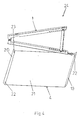
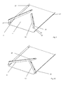
- FIGS. 9 and 10 show a base unit 4 with a support member 2 and a spacer 13.
- the support member 2 and the spacer 13 have at their ends hook elements 25, each with two hooks 26.
- the support element 2 is inserted by means of its hook element 25 in one of the four engagement openings 27 of the base unit 4.
- the spacer 13 is in FIG. 9 not yet mounted. In FIG. 10 Both support element 2 and spacer 13 are connected to the base unit 4.
- Support element 2 and spacers 13 are interconnected.
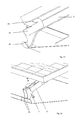
- the spacer 13 made of a U-profile has at its end opposite the hook element 25 a positioning element 28 in the form of a profile projection. This is according to FIG. 11 inserted into an opening on the also U-shaped support member 2.
- the end portion of the spacer 13 can be inserted into the U-profile of the support member 2.
- a laterally pushed through the legs of the U-profile screw ( FIG. 11 ) connects the support member 2 and the spacer 13 with each other.
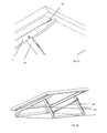
- FIG. 12 shows the fully assembled device with base element 4, and two mounted thereon units of support member 2 and spacer 13. On the support members 2, the solar module is installed.
- FIGS. 13 and 14 two lateral views of the device are shown with fastener 29 arranged thereon.
- the fastening element 29 has a hook-shaped end region, which engages in an engagement 30 on the underside of the solar module.
- the other end region of the fastening element 29 is rail-shaped and has a slot which corresponds to a slot on the support member 2.
- the rail-shaped end region is designed as an angle profile, so that it can be placed positively around a side edge of the support element.
- FIG. 15 is the fastening element 29 facing away from the end of the support member 2 is shown, which also engages with its end portion in an opening 31 on the underside of the solar module.
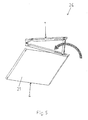
- FIG. 16 finally shows a completely assembled device with solar module arranged thereon. Between the spacers 13 of the device, a transverse strut 31 is additionally mounted.
- the base unit 4 is connected to two support elements 2 and two spacers 13.
- the hook elements 25 located on one end side of the support elements 2 and spacers 13 are thus connected to openings in the legs of the U-shaped base unit 4 such that the hooks 26 engage around the openings and around the material of the base unit 4.
- the mechanic performs a simple rotational movement until the hooks 26 are fully engaged.
- support element 2 and spacers 13 are connected together.
- the support member 2 is placed with its downwardly facing side on the end portion of the spacer 13, which has a positioning element 28 there. This positioning element 28 is inserted into a corresponding slot of the support element 2.
- the support member 2 has a plurality of such slots, so that depending on the choice of the slot, a different inclination of the support member 2 and thus also of the solar module can be achieved. After the pre-positioning of support member 2 and spacer 13, these are additionally secured with a screw which is pushed from the side by the support member 2 and the end portion of the spacer 13 disposed therein. It is also conceivable an embodiment in which the spacer 13 rests on the support member 2 without further notice.
- the base unit 4 can be set up at its destination.
- the upward-facing side the base unit 4 are occupied, for example, with bulk material, so that a sufficient weight resting on it. It would also be possible to screw the base unit 4 to a substrate.
- the solar module is installed on the fully assembled device.
- the solar module is first according to FIG. 15 connected to the end portion of the support member 2, which is closest to the spacer 13.
- the end of the support element 2 is thereby (partially or completely) inserted into an opening 31 on the underside of the solar module.
- the attachment of the solar module takes place at the opposite end of the support element 2.
- the fastening element 29, which (in accordance with FIG. 13 ) has a hook-shaped and a rail-shaped end portion.
- the hook-shaped end portion is hooked on the underside of the solar module in an engagement 30.
- the fastener 29 is pulled substantially in the direction of the hook 26 of the support member 2 until the solar module is firmly connected to the device.
- the fastener 29 slots are one above the other and can be bolted together.
- the cross member 32 between the spacers 13 are attached. Also for this purpose are slots in both the cross member 32 and the spacers 13th
Landscapes
- Engineering & Computer Science (AREA)
- Physics & Mathematics (AREA)
- Life Sciences & Earth Sciences (AREA)
- Sustainable Development (AREA)
- Sustainable Energy (AREA)
- Thermal Sciences (AREA)
- Chemical & Material Sciences (AREA)
- Combustion & Propulsion (AREA)
- Mechanical Engineering (AREA)
- General Engineering & Computer Science (AREA)
- Photovoltaic Devices (AREA)
- Roof Covering Using Slabs Or Stiff Sheets (AREA)
Applications Claiming Priority (1)
| Application Number | Priority Date | Filing Date | Title |
|---|---|---|---|
| DE202010015848U DE202010015848U1 (de) | 2010-11-26 | 2010-11-26 | Vorrichtung zum Anordnen wenigstens eines Solarmoduls an einem Untergrund |
Publications (3)
| Publication Number | Publication Date |
|---|---|
| EP2458301A2 true EP2458301A2 (fr) | 2012-05-30 |
| EP2458301A3 EP2458301A3 (fr) | 2013-01-23 |
| EP2458301B1 EP2458301B1 (fr) | 2014-07-30 |
Family
ID=43603935
Family Applications (1)
| Application Number | Title | Priority Date | Filing Date |
|---|---|---|---|
| EP11006460.7A Not-in-force EP2458301B1 (fr) | 2010-11-26 | 2011-08-05 | Dispositif d'agencement d'au moins un module solaire dans un sous-sol |
Country Status (3)
| Country | Link |
|---|---|
| EP (1) | EP2458301B1 (fr) |
| DE (1) | DE202010015848U1 (fr) |
| ES (1) | ES2522829T3 (fr) |
Cited By (3)
| Publication number | Priority date | Publication date | Assignee | Title |
|---|---|---|---|---|
| DE202014004487U1 (de) | 2014-06-04 | 2015-09-07 | Schletter Gmbh | Vorrichtung zum Halten von Solarmodulrahmen |
| DE102014007971A1 (de) | 2014-06-04 | 2015-12-17 | Schletter Gmbh | Vorrichtung zum Halten von Solarmodulrahmen |
| CN117294226A (zh) * | 2023-08-14 | 2023-12-26 | 敏捷智慧能源科技(绍兴)有限公司 | 一种光伏支架及光伏板总成 |
Families Citing this family (8)
| Publication number | Priority date | Publication date | Assignee | Title |
|---|---|---|---|---|
| US20120298201A1 (en) * | 2011-11-18 | 2012-11-29 | Erich Kai Stephan | Solar panel racking system |
| US20150059381A1 (en) * | 2011-12-20 | 2015-03-05 | Dometric S.a.r.I. | Mobile generator device and cooling system |
| ITBO20120063A1 (it) * | 2012-02-09 | 2013-08-10 | Green Business S R L | Struttura articolata per il supporto di pannelli fotovoltaici |
| BE1020837A3 (fr) * | 2012-07-20 | 2014-06-03 | Mc Solar | Systeme de fixation pour panneaux solaires. |
| KR20140028181A (ko) * | 2012-07-25 | 2014-03-10 | 삼성에스디아이 주식회사 | 태양광 발전 장치 |
| KR101460719B1 (ko) | 2012-08-28 | 2014-11-13 | 엘지전자 주식회사 | 지지 프레임 및 이를 포함하는 태양광 발전 장치 |
| DE202013002767U1 (de) | 2013-03-22 | 2013-05-28 | Lorenz-Montagesysteme Gmbh | Ausgleichende Seitverbindung von Solarmodulen |
| CH720824B1 (de) * | 2023-06-01 | 2026-04-15 | Rene Schmid | Montageeinrichtung und Montageverfahren für PV Module an Gebirgeflächen |
Citations (1)
| Publication number | Priority date | Publication date | Assignee | Title |
|---|---|---|---|---|
| DE202009007517U1 (de) | 2009-05-20 | 2009-12-10 | Trienergy Gmbh | Ständer für rechteckige Solarmodule |
Family Cites Families (1)
| Publication number | Priority date | Publication date | Assignee | Title |
|---|---|---|---|---|
| US6046399A (en) * | 1997-01-13 | 2000-04-04 | Kapner; Mark | Roofing panels with integral brackets for accepting inclined solar panels |
-
2010
- 2010-11-26 DE DE202010015848U patent/DE202010015848U1/de not_active Expired - Lifetime
-
2011
- 2011-08-05 ES ES11006460.7T patent/ES2522829T3/es active Active
- 2011-08-05 EP EP11006460.7A patent/EP2458301B1/fr not_active Not-in-force
Patent Citations (1)
| Publication number | Priority date | Publication date | Assignee | Title |
|---|---|---|---|---|
| DE202009007517U1 (de) | 2009-05-20 | 2009-12-10 | Trienergy Gmbh | Ständer für rechteckige Solarmodule |
Cited By (3)
| Publication number | Priority date | Publication date | Assignee | Title |
|---|---|---|---|---|
| DE202014004487U1 (de) | 2014-06-04 | 2015-09-07 | Schletter Gmbh | Vorrichtung zum Halten von Solarmodulrahmen |
| DE102014007971A1 (de) | 2014-06-04 | 2015-12-17 | Schletter Gmbh | Vorrichtung zum Halten von Solarmodulrahmen |
| CN117294226A (zh) * | 2023-08-14 | 2023-12-26 | 敏捷智慧能源科技(绍兴)有限公司 | 一种光伏支架及光伏板总成 |
Also Published As
| Publication number | Publication date |
|---|---|
| EP2458301B1 (fr) | 2014-07-30 |
| DE202010015848U1 (de) | 2011-02-17 |
| ES2522829T3 (es) | 2014-11-18 |
| EP2458301A3 (fr) | 2013-01-23 |
Similar Documents
| Publication | Publication Date | Title |
|---|---|---|
| EP2458301B1 (fr) | Dispositif d'agencement d'au moins un module solaire dans un sous-sol | |
| EP2435768B1 (fr) | Dispositif servant à fixer un rail de montage sur une tige filetée | |
| DE102018221183B3 (de) | Justierbeschlag und Tragsystem für Solarmodule | |
| DE102013112645B3 (de) | Türband | |
| DE202012012290U1 (de) | Befestigungsvorrichtung zur Befestigung plattenförmiger Bauteile | |
| EP2685111A1 (fr) | Dispositif de serrage de connexion amovibles de deux pièces profilées | |
| EP0671581A2 (fr) | Rail de montage pour la fixation de tuyaux ou similaires | |
| EP3643847B1 (fr) | Système de fixation et rail pour un système de fixation | |
| AT520220B1 (de) | Montageträger zur Montage von Oberschienen | |
| EP2253902B1 (fr) | Ensemble de composants pour le montage de modules solaires sur un toit | |
| EP3787137A1 (fr) | Dispositif de raccordement, garniture de raccordement et chemin de câbles | |
| EP3241974B1 (fr) | Système pour un joint d'étanchéité, en particulier pour un joint de seuil ou pour un joint de sol s'abaissant automatiquement | |
| EP3071896B1 (fr) | Support de montage pour une enceinte et méthode de monter une enceinte utilisant ledit support | |
| EP2869417B1 (fr) | Dispositif de liaison de sections de conduit de câble et conduit de câble | |
| EP3127789B1 (fr) | Ranche pour un montage de véhicule utilitaire et système de sécurisation de charge, montage de véhicule utilitaire et véhicule utilitaire comprenant une telle ranche | |
| EP2400239A1 (fr) | Dispositif de réglage et système de montage | |
| AT510784B1 (de) | Sanitärwannenträger, insbesondere duschwannenträger | |
| DE102012004773A1 (de) | Vorrichtung für die Halterung von Photovoltaikmodulen auf Freiflächen | |
| EP2458302B1 (fr) | Elément de liaison et dispositif de fixation de modules solaires | |
| EP3067486B1 (fr) | Serrure pour grille | |
| DE202012001078U1 (de) | Befestigungssystem für Solarmodule | |
| DE202012102863U1 (de) | Befestigungseinrichtung für ein Flächenelement an einem C-Profil | |
| EP3483047B1 (fr) | Dispositif de retenue pour un véhicule utilitaire, agencement d'un rancher doté d'un dispositif de retenue, véhicule utilitaire, procédé de fabrication d'un dispositif de retenue et procédé de montage d'un dispositif de retenue sur un rancher | |
| EP1659332A2 (fr) | Cadre encastré et luminaire correspondant | |
| EP2136027B1 (fr) | Raccordement d'angle pour cadre de porte et de fenêtre |
Legal Events
| Date | Code | Title | Description |
|---|---|---|---|
| PUAI | Public reference made under article 153(3) epc to a published international application that has entered the european phase |
Free format text: ORIGINAL CODE: 0009012 |
|
| AK | Designated contracting states |
Kind code of ref document: A2 Designated state(s): AL AT BE BG CH CY CZ DE DK EE ES FI FR GB GR HR HU IE IS IT LI LT LU LV MC MK MT NL NO PL PT RO RS SE SI SK SM TR |
|
| AX | Request for extension of the european patent |
Extension state: BA ME |
|
| PUAL | Search report despatched |
Free format text: ORIGINAL CODE: 0009013 |
|
| AK | Designated contracting states |
Kind code of ref document: A3 Designated state(s): AL AT BE BG CH CY CZ DE DK EE ES FI FR GB GR HR HU IE IS IT LI LT LU LV MC MK MT NL NO PL PT RO RS SE SI SK SM TR |
|
| AX | Request for extension of the european patent |
Extension state: BA ME |
|
| RIC1 | Information provided on ipc code assigned before grant |
Ipc: F24J 2/52 20060101AFI20121214BHEP Ipc: H01L 31/042 20060101ALI20121214BHEP Ipc: F24J 2/54 20060101ALI20121214BHEP |
|
| 17P | Request for examination filed |
Effective date: 20130722 |
|
| REG | Reference to a national code |
Ref country code: DE Ref legal event code: R079 Ref document number: 502011003863 Country of ref document: DE Free format text: PREVIOUS MAIN CLASS: F24J0002520000 Ipc: F24J0002460000 |
|
| GRAP | Despatch of communication of intention to grant a patent |
Free format text: ORIGINAL CODE: EPIDOSNIGR1 |
|
| RIC1 | Information provided on ipc code assigned before grant |
Ipc: H01L 31/042 20060101ALI20140114BHEP Ipc: F24J 2/46 20060101AFI20140114BHEP Ipc: F24J 2/52 20060101ALI20140114BHEP Ipc: F24J 2/54 20060101ALI20140114BHEP |
|
| INTG | Intention to grant announced |
Effective date: 20140217 |
|
| GRAS | Grant fee paid |
Free format text: ORIGINAL CODE: EPIDOSNIGR3 |
|
| GRAA | (expected) grant |
Free format text: ORIGINAL CODE: 0009210 |
|
| AK | Designated contracting states |
Kind code of ref document: B1 Designated state(s): AL AT BE BG CH CY CZ DE DK EE ES FI FR GB GR HR HU IE IS IT LI LT LU LV MC MK MT NL NO PL PT RO RS SE SI SK SM TR |
|
| REG | Reference to a national code |
Ref country code: GB Ref legal event code: FG4D Free format text: NOT ENGLISH |
|
| REG | Reference to a national code |
Ref country code: CH Ref legal event code: EP |
|
| REG | Reference to a national code |
Ref country code: AT Ref legal event code: REF Ref document number: 680173 Country of ref document: AT Kind code of ref document: T Effective date: 20140815 |
|
| REG | Reference to a national code |
Ref country code: IE Ref legal event code: FG4D Free format text: LANGUAGE OF EP DOCUMENT: GERMAN |
|
| REG | Reference to a national code |
Ref country code: DE Ref legal event code: R096 Ref document number: 502011003863 Country of ref document: DE Effective date: 20140911 |
|
| REG | Reference to a national code |
Ref country code: ES Ref legal event code: FG2A Ref document number: 2522829 Country of ref document: ES Kind code of ref document: T3 Effective date: 20141118 |
|
| REG | Reference to a national code |
Ref country code: NL Ref legal event code: T3 |
|
| REG | Reference to a national code |
Ref country code: LT Ref legal event code: MG4D |
|
| PG25 | Lapsed in a contracting state [announced via postgrant information from national office to epo] |
Ref country code: SE Free format text: LAPSE BECAUSE OF FAILURE TO SUBMIT A TRANSLATION OF THE DESCRIPTION OR TO PAY THE FEE WITHIN THE PRESCRIBED TIME-LIMIT Effective date: 20140730 Ref country code: FI Free format text: LAPSE BECAUSE OF FAILURE TO SUBMIT A TRANSLATION OF THE DESCRIPTION OR TO PAY THE FEE WITHIN THE PRESCRIBED TIME-LIMIT Effective date: 20140730 Ref country code: LT Free format text: LAPSE BECAUSE OF FAILURE TO SUBMIT A TRANSLATION OF THE DESCRIPTION OR TO PAY THE FEE WITHIN THE PRESCRIBED TIME-LIMIT Effective date: 20140730 Ref country code: GR Free format text: LAPSE BECAUSE OF FAILURE TO SUBMIT A TRANSLATION OF THE DESCRIPTION OR TO PAY THE FEE WITHIN THE PRESCRIBED TIME-LIMIT Effective date: 20141031 Ref country code: BG Free format text: LAPSE BECAUSE OF FAILURE TO SUBMIT A TRANSLATION OF THE DESCRIPTION OR TO PAY THE FEE WITHIN THE PRESCRIBED TIME-LIMIT Effective date: 20141030 Ref country code: NO Free format text: LAPSE BECAUSE OF FAILURE TO SUBMIT A TRANSLATION OF THE DESCRIPTION OR TO PAY THE FEE WITHIN THE PRESCRIBED TIME-LIMIT Effective date: 20141030 Ref country code: PT Free format text: LAPSE BECAUSE OF FAILURE TO SUBMIT A TRANSLATION OF THE DESCRIPTION OR TO PAY THE FEE WITHIN THE PRESCRIBED TIME-LIMIT Effective date: 20141202 |
|
| PG25 | Lapsed in a contracting state [announced via postgrant information from national office to epo] |
Ref country code: PL Free format text: LAPSE BECAUSE OF FAILURE TO SUBMIT A TRANSLATION OF THE DESCRIPTION OR TO PAY THE FEE WITHIN THE PRESCRIBED TIME-LIMIT Effective date: 20140730 Ref country code: CY Free format text: LAPSE BECAUSE OF FAILURE TO SUBMIT A TRANSLATION OF THE DESCRIPTION OR TO PAY THE FEE WITHIN THE PRESCRIBED TIME-LIMIT Effective date: 20140730 Ref country code: RS Free format text: LAPSE BECAUSE OF FAILURE TO SUBMIT A TRANSLATION OF THE DESCRIPTION OR TO PAY THE FEE WITHIN THE PRESCRIBED TIME-LIMIT Effective date: 20140730 Ref country code: IS Free format text: LAPSE BECAUSE OF FAILURE TO SUBMIT A TRANSLATION OF THE DESCRIPTION OR TO PAY THE FEE WITHIN THE PRESCRIBED TIME-LIMIT Effective date: 20141130 Ref country code: HR Free format text: LAPSE BECAUSE OF FAILURE TO SUBMIT A TRANSLATION OF THE DESCRIPTION OR TO PAY THE FEE WITHIN THE PRESCRIBED TIME-LIMIT Effective date: 20140730 Ref country code: LV Free format text: LAPSE BECAUSE OF FAILURE TO SUBMIT A TRANSLATION OF THE DESCRIPTION OR TO PAY THE FEE WITHIN THE PRESCRIBED TIME-LIMIT Effective date: 20140730 |
|
| PG25 | Lapsed in a contracting state [announced via postgrant information from national office to epo] |
Ref country code: MC Free format text: LAPSE BECAUSE OF FAILURE TO SUBMIT A TRANSLATION OF THE DESCRIPTION OR TO PAY THE FEE WITHIN THE PRESCRIBED TIME-LIMIT Effective date: 20140730 Ref country code: EE Free format text: LAPSE BECAUSE OF FAILURE TO SUBMIT A TRANSLATION OF THE DESCRIPTION OR TO PAY THE FEE WITHIN THE PRESCRIBED TIME-LIMIT Effective date: 20140730 Ref country code: RO Free format text: LAPSE BECAUSE OF FAILURE TO SUBMIT A TRANSLATION OF THE DESCRIPTION OR TO PAY THE FEE WITHIN THE PRESCRIBED TIME-LIMIT Effective date: 20140730 Ref country code: DK Free format text: LAPSE BECAUSE OF FAILURE TO SUBMIT A TRANSLATION OF THE DESCRIPTION OR TO PAY THE FEE WITHIN THE PRESCRIBED TIME-LIMIT Effective date: 20140730 Ref country code: SK Free format text: LAPSE BECAUSE OF FAILURE TO SUBMIT A TRANSLATION OF THE DESCRIPTION OR TO PAY THE FEE WITHIN THE PRESCRIBED TIME-LIMIT Effective date: 20140730 Ref country code: CZ Free format text: LAPSE BECAUSE OF FAILURE TO SUBMIT A TRANSLATION OF THE DESCRIPTION OR TO PAY THE FEE WITHIN THE PRESCRIBED TIME-LIMIT Effective date: 20140730 |
|
| REG | Reference to a national code |
Ref country code: DE Ref legal event code: R097 Ref document number: 502011003863 Country of ref document: DE |
|
| REG | Reference to a national code |
Ref country code: IE Ref legal event code: MM4A |
|
| PLBE | No opposition filed within time limit |
Free format text: ORIGINAL CODE: 0009261 |
|
| STAA | Information on the status of an ep patent application or granted ep patent |
Free format text: STATUS: NO OPPOSITION FILED WITHIN TIME LIMIT |
|
| 26N | No opposition filed |
Effective date: 20150504 |
|
| PG25 | Lapsed in a contracting state [announced via postgrant information from national office to epo] |
Ref country code: IE Free format text: LAPSE BECAUSE OF NON-PAYMENT OF DUE FEES Effective date: 20140805 |
|
| PG25 | Lapsed in a contracting state [announced via postgrant information from national office to epo] |
Ref country code: SI Free format text: LAPSE BECAUSE OF FAILURE TO SUBMIT A TRANSLATION OF THE DESCRIPTION OR TO PAY THE FEE WITHIN THE PRESCRIBED TIME-LIMIT Effective date: 20140730 |
|
| PG25 | Lapsed in a contracting state [announced via postgrant information from national office to epo] |
Ref country code: SM Free format text: LAPSE BECAUSE OF FAILURE TO SUBMIT A TRANSLATION OF THE DESCRIPTION OR TO PAY THE FEE WITHIN THE PRESCRIBED TIME-LIMIT Effective date: 20140730 |
|
| PG25 | Lapsed in a contracting state [announced via postgrant information from national office to epo] |
Ref country code: MT Free format text: LAPSE BECAUSE OF FAILURE TO SUBMIT A TRANSLATION OF THE DESCRIPTION OR TO PAY THE FEE WITHIN THE PRESCRIBED TIME-LIMIT Effective date: 20140730 |
|
| PG25 | Lapsed in a contracting state [announced via postgrant information from national office to epo] |
Ref country code: HU Free format text: LAPSE BECAUSE OF FAILURE TO SUBMIT A TRANSLATION OF THE DESCRIPTION OR TO PAY THE FEE WITHIN THE PRESCRIBED TIME-LIMIT; INVALID AB INITIO Effective date: 20110805 Ref country code: LU Free format text: LAPSE BECAUSE OF NON-PAYMENT OF DUE FEES Effective date: 20140805 Ref country code: TR Free format text: LAPSE BECAUSE OF FAILURE TO SUBMIT A TRANSLATION OF THE DESCRIPTION OR TO PAY THE FEE WITHIN THE PRESCRIBED TIME-LIMIT Effective date: 20140730 |
|
| REG | Reference to a national code |
Ref country code: FR Ref legal event code: PLFP Year of fee payment: 6 |
|
| REG | Reference to a national code |
Ref country code: FR Ref legal event code: PLFP Year of fee payment: 7 |
|
| PGFP | Annual fee paid to national office [announced via postgrant information from national office to epo] |
Ref country code: NL Payment date: 20170821 Year of fee payment: 7 |
|
| PGFP | Annual fee paid to national office [announced via postgrant information from national office to epo] |
Ref country code: CH Payment date: 20170821 Year of fee payment: 7 Ref country code: FR Payment date: 20170822 Year of fee payment: 7 Ref country code: GB Payment date: 20170822 Year of fee payment: 7 Ref country code: IT Payment date: 20170828 Year of fee payment: 7 Ref country code: ES Payment date: 20170928 Year of fee payment: 7 |
|
| REG | Reference to a national code |
Ref country code: DE Ref legal event code: R079 Ref document number: 502011003863 Country of ref document: DE Free format text: PREVIOUS MAIN CLASS: F24J0002460000 Ipc: F24S0040000000 |
|
| PGFP | Annual fee paid to national office [announced via postgrant information from national office to epo] |
Ref country code: BE Payment date: 20170821 Year of fee payment: 7 Ref country code: AT Payment date: 20170822 Year of fee payment: 7 |
|
| PG25 | Lapsed in a contracting state [announced via postgrant information from national office to epo] |
Ref country code: MK Free format text: LAPSE BECAUSE OF FAILURE TO SUBMIT A TRANSLATION OF THE DESCRIPTION OR TO PAY THE FEE WITHIN THE PRESCRIBED TIME-LIMIT Effective date: 20140730 |
|
| PG25 | Lapsed in a contracting state [announced via postgrant information from national office to epo] |
Ref country code: AL Free format text: LAPSE BECAUSE OF FAILURE TO SUBMIT A TRANSLATION OF THE DESCRIPTION OR TO PAY THE FEE WITHIN THE PRESCRIBED TIME-LIMIT Effective date: 20140730 |
|
| REG | Reference to a national code |
Ref country code: CH Ref legal event code: PL |
|
| REG | Reference to a national code |
Ref country code: NL Ref legal event code: MM Effective date: 20180901 |
|
| REG | Reference to a national code |
Ref country code: AT Ref legal event code: MM01 Ref document number: 680173 Country of ref document: AT Kind code of ref document: T Effective date: 20180805 |
|
| GBPC | Gb: european patent ceased through non-payment of renewal fee |
Effective date: 20180805 |
|
| PG25 | Lapsed in a contracting state [announced via postgrant information from national office to epo] |
Ref country code: AT Free format text: LAPSE BECAUSE OF NON-PAYMENT OF DUE FEES Effective date: 20180805 Ref country code: LI Free format text: LAPSE BECAUSE OF NON-PAYMENT OF DUE FEES Effective date: 20180831 Ref country code: CH Free format text: LAPSE BECAUSE OF NON-PAYMENT OF DUE FEES Effective date: 20180831 |
|
| REG | Reference to a national code |
Ref country code: BE Ref legal event code: MM Effective date: 20180831 |
|
| PG25 | Lapsed in a contracting state [announced via postgrant information from national office to epo] |
Ref country code: NL Free format text: LAPSE BECAUSE OF NON-PAYMENT OF DUE FEES Effective date: 20180901 |
|
| PG25 | Lapsed in a contracting state [announced via postgrant information from national office to epo] |
Ref country code: IT Free format text: LAPSE BECAUSE OF NON-PAYMENT OF DUE FEES Effective date: 20180805 |
|
| PG25 | Lapsed in a contracting state [announced via postgrant information from national office to epo] |
Ref country code: BE Free format text: LAPSE BECAUSE OF NON-PAYMENT OF DUE FEES Effective date: 20180831 Ref country code: FR Free format text: LAPSE BECAUSE OF NON-PAYMENT OF DUE FEES Effective date: 20180831 |
|
| REG | Reference to a national code |
Ref country code: ES Ref legal event code: FD2A Effective date: 20190918 |
|
| PG25 | Lapsed in a contracting state [announced via postgrant information from national office to epo] |
Ref country code: ES Free format text: LAPSE BECAUSE OF NON-PAYMENT OF DUE FEES Effective date: 20180806 Ref country code: GB Free format text: LAPSE BECAUSE OF NON-PAYMENT OF DUE FEES Effective date: 20180805 |
|
| P01 | Opt-out of the competence of the unified patent court (upc) registered |
Effective date: 20230508 |
|
| PGFP | Annual fee paid to national office [announced via postgrant information from national office to epo] |
Ref country code: DE Payment date: 20240821 Year of fee payment: 14 |
|
| REG | Reference to a national code |
Ref country code: DE Ref legal event code: R119 Ref document number: 502011003863 Country of ref document: DE |
|
| PG25 | Lapsed in a contracting state [announced via postgrant information from national office to epo] |
Ref country code: DE Free format text: LAPSE BECAUSE OF NON-PAYMENT OF DUE FEES Effective date: 20260303 |