EP3067486B1 - Serrure pour grille - Google Patents
Serrure pour grille Download PDFInfo
- Publication number
- EP3067486B1 EP3067486B1 EP16160203.2A EP16160203A EP3067486B1 EP 3067486 B1 EP3067486 B1 EP 3067486B1 EP 16160203 A EP16160203 A EP 16160203A EP 3067486 B1 EP3067486 B1 EP 3067486B1
- Authority
- EP
- European Patent Office
- Prior art keywords
- securing
- section
- grating
- fastening device
- component
- Prior art date
- Legal status (The legal status is an assumption and is not a legal conclusion. Google has not performed a legal analysis and makes no representation as to the accuracy of the status listed.)
- Active
Links
Images



Classifications
-
- E—FIXED CONSTRUCTIONS
- E04—BUILDING
- E04C—STRUCTURAL ELEMENTS; BUILDING MATERIALS
- E04C2/00—Building elements of relatively thin form for the construction of parts of buildings, e.g. sheet materials, slabs, or panels
- E04C2/30—Building elements of relatively thin form for the construction of parts of buildings, e.g. sheet materials, slabs, or panels characterised by the shape or structure
- E04C2/42—Gratings; Grid-like panels
- E04C2/428—Separate connecting means, e.g. connecting gratings to underlying structure
-
- E—FIXED CONSTRUCTIONS
- E04—BUILDING
- E04F—FINISHING WORK ON BUILDINGS, e.g. STAIRS, FLOORS
- E04F17/00—Vertical ducts; Channels, e.g. for drainage
- E04F17/06—Light shafts, e.g. for cellars
-
- E—FIXED CONSTRUCTIONS
- E05—LOCKS; KEYS; WINDOW OR DOOR FITTINGS; SAFES
- E05B—LOCKS; ACCESSORIES THEREFOR; HANDCUFFS
- E05B65/00—Locks or fastenings for special use
- E05B65/10—Locks or fastenings for special use for panic or emergency doors
- E05B65/1033—Locks or fastenings for special use for panic or emergency doors emergency release of windows, window grills, escape hatches or the like
Definitions
- the present invention relates to a fastening device for securing a first component with a lattice structure on a second component, in particular for securing a grating in a light shaft according to claim 1.
- Grating fastening devices are known from the prior art and are used primarily, but not only, to secure a grating in a light shaft, against the forcible removal of the grating by unauthorized persons. It is also conceivable to use it to secure crates, for example cellar compartment grids or other barriers.
- fastening devices are formed, for example, in the form of hook-shaped or multi-part plate-like constructions from a plate and a rod.
- Fastening devices of the generic type are designed in such a way that a square or round plate is applied to the lattice structure of a first component from above and is clamped down through the lattice structure to a second component via a fastening structure in the form of a chain or a metal strip.
- Generic fastening devices are for example in the utility model DE 76 38 968 U , the utility model DE 77 13 327 U as well as the utility model DE 77 38 787 U1 disclosed. These show various designs of safety devices for gratings, consisting of a rod-like element and a plate, the plate being placed above the lattice structure and through for anchoring from below with a rod or the like the grating is tensioned through and fixed to a wall of the light shaft.
- Another known possibility is a design as a simple hook, which is hung on a rod section of the lattice structure and attached and fixed downwards to a second component.
- the utility model GM 75 30 970 discloses a holding device for grids on shafts or the like.
- the holding device engages around the grating in the shape of a hook by means of a holding rod designed in the form of a hook.
- This holding rod is provided with a clamping screw for fastening to, for example, shaft walls.
- the screw head is covered and thus secured by a wing consisting of an angle piece.
- the opposing hook legs can be fixed to one another by a connecting screw.
- a holding device with a U-shaped hook in which both hook ends extend down to the bracing and are anchored there.
- the U-shaped hook is connected to the grating via a rod section.
- the DE 40 06 321 A1 describes a safety device for cellar gratings, comprising a grid safety section and a train safety section.
- a slotted hook which forms the lattice securing section
- the securing device can overlap two rod sections of the lattice structure.
- the hook is slotted on the two vertically parallel sections.
- a cover plate can be welded onto the top of the hook in order to cover a larger surface of the lattice structure.
- the hook can be detachably hooked into the tension protection section and can be inserted through the grid from above.
- Providing a plurality of hooks to grip around a plurality of rod sections is not envisaged. With such a safety device only two rod sections can be enclosed.
- the holding device in the DE 28 49 878 C2 engages around the grating in the shape of a hook by means of a slotted holding rod designed in the shape of a hook. This allows two bars to be enclosed at the same time.
- the support rod is provided with a clamping screw for fastening to the shaft walls using an angle piece.
- the hook can be slotted and enclose at least one rod section of the grating.
- a holding device of this type does not encompass a large number of rod sections.
- connection element for gratings to be attached to ceilings, so-called ceiling support structure of grid grids.
- the connecting element is designed in one piece as an elongated sheet metal and comprises a slotted hook at one end for grasping adjacent bars.
- the hook can therefore encompass two rod sections of the grating.
- the connecting element has a bending bead which can be pushed into a retaining rail curved in a complementary manner.
- the disclosure shows a non-generic ceiling support structure of grid grids, in which the holding device is attached above the grating and, moreover, no one-piece design of a hook comb.
- the DE 75 01 257 U shows a securing device for gratings, comprising a grating securing section and a train securing section.
- the lattice securing section has a hook which can engage in a rod section of the lattice structure and which can be hooked into a tension securing section.
- a grip of three or more rod sections is not given with such a design.
- the DE 90 02 369 U1 discloses a securing device for securing a grating in a light shaft.
- This has a slotted safety hook with a head-side arranged, for. B. welded, cover plate.
- the safety hook is slotted in a plane running at right angles to the grating plane. Due to the slotted design, the securing hook can encompass two rod sections of the grating in a U-shape.
- the safety hook is attached to the shaft wall with a pull safety section.
- the train protection section an opening into which the locking hook engages and hooks.
- a safety device with an L-shaped safety bracket.
- the safety bracket runs partially parallel to the shaft wall and partially parallel to the underside of the grating.
- a cover plate can be attached between the grating and bracket and above the grating, which covers the meshes of the grating in this area and which is connected to the safety bracket and the grating with at least two tensioning screws.
- the DE 29 13 112 A1 likewise shows a securing device for a grating of a cellar shaft with an L-shaped securing bracket.
- the horizontal section of the safety bracket is connected by a bolt to a cover plate which is attached above the grating and has a hole.
- the bolt is screwed with a nut and a lock nut underneath the grating.
- An eyelet or the like is mounted on the inside of the light well so that the eyelet can be pushed into a recess in the safety bracket and secured with a lock.
- the US 5 911 664 A shows a fastening system for a grating with an integrated frame component for the formation of a running surface in an area that can be washed over by water, such as a gangway, a railing staircase, in swimming platforms or the like. Due to the susceptibility of metal grids to corrosion in this area, a grating made of fiberglass is used. Furthermore, the grating is mechanically fastened to the frame component with a terminal strip.
- this component can be bent or levered out of its plane by unauthorized persons and rotated around the axis of rotation thus formed so that unauthorized persons can enter the building through the light shaft or the basement window.
- the plate-like designs consisting of at least one plate and a holding rod as well as further fixing elements and profiles, are constructed in several parts, which increases the manufacturing costs and the assembly effort and makes assembly more difficult.
- a large number of fastening devices also restrict the incidence of light through the grid structure and thus into the light shaft or the basement window.
- the object of the invention is to overcome the disadvantages of the known arrangements.
- Another task here is not to unnecessarily restrict the incidence of light into the light shaft through the lattice structure of the first component.
- the aim is also to provide a fastening device for securing a grating or the like, whereby a security against the intrusion of unauthorized persons with a resistance class 3 or higher according to DIN EN 1627 or DIN V ENV 1627 in the version of the year 2016 can be achieved.
- DIN EN 1627 or DIN V ENV 1627 in the version of the year 2016 can be achieved.
- a fastening device for securing a first component with a lattice structure, comprising a plurality of meshes delimited by rod sections on a second component, the first component being a grating and the second component being a light shaft, the fastening device being a grid securing section for connecting the Fastening device with the lattice structure and a tension securing section for connecting the fastening device to the second component, wherein the lattice securing section is formed in one piece or in several parts.
- the grid securing section has at least three to ten, in particular seven or eight securing units, which are detachably and / or non-detachably connected to a base body of the grid securing section, in particular screwed, riveted, welded or soldered and which are each connected to a rod section of the
- the lattice structure can be connected, the lattice securing section being plate-shaped and the securing units being shaped and attached to a longitudinal edge of the lattice securing section in such a way that they can enclose several rod sections of the lattice structure in a comb-like manner and each securing unit is U-hook-shaped in the end area and a rod section of the first component is at least partially and only the comb-like securing units without planar components are visible from a position above the first component, so that light does not enter the lattice structure is limited and optically the fuse units are barely perceived, and at least three rod sections of the lattice
- a one-piece design of the lattice securing section enables simple assembly and inexpensive manufacture of the fastening device.
- a multi-part design of the lattice securing section enables easier assembly, as well as scaling and adaptability of the lattice securing device.
- the grid securing section can preferably be straight, but curved or curved arrangements of the securing units of the grid securing section are also conceivable.
- the grid securing section can also have a rounded shape and have the shape of a pipe section, or the grid securing section can be angled.
- the lattice securing section in the form of a cylinder, for example as a tubular or rectangular cylinder, are also conceivable, the upper edge of the lattice securing section having a plurality of securing units which can be used for fastening to rod sections of the first component.
- the securing units can be detachably and / or non-detachably connected to the base body of the grid securing section.
- the fuse units can be screwed, riveted, welded or soldered on.
- safety screws or bolts or screws in conjunction with shear nuts, shear bolts or the like can be used when assembling the securing sections.
- safety screws have a special screw head with a special screw head drive, for example in the form of an internal multi-tooth or a Torx with a pin or pin.
- a special screw head drive for example in the form of an internal multi-tooth or a Torx with a pin or pin.
- Such safety screws are difficult to dismantle or cannot be dismantled simply by unscrewing them using special tools, shear nuts or bolts.
- the respective rod section is securely encompassed or encompassed and the meshes of the lattice structure are hardly covered, so that the incidence of light into the lattice structure is not restricted becomes.
- the end regions of the U-shaped securing units preferably overlap the rod sections of the lattice structure by at least an additional 5 mm so that the end regions can no longer be bent open by force.
- a connecting screw can be used to fix the end areas of the U-shaped securing units with the respective opposite areas of the respective securing unit with a screw, rivet, wire or rope, so that the rod sections are encompassed all around by the securing unit.
- a short long side of a first component, especially a grating, with eight safety units can secure a grating width of approx. 30 cm very well.
- a possible intruder would have to cut through almost the entire grating twice in width, which would require at least twenty cuts.
- the number of rod sections to be cut when removing the lattice structure from the mounted fastening device is twice the number of securing units plus at least four rod sections in the edge area.
- a lattice structure in particular of a light shaft lattice, comprises mechanically reinforced support rods as longitudinal rods for receiving a support weight and transverse rods for connecting the support rods.
- the height of the support rods is greater than that of the transverse rods, and the width of a support rod can also be greater than that of a transverse rod.
- the lattice securing section is plate-shaped and the securing units are shaped and attached to a longitudinal edge of the lattice securing section in such a way that they can enclose several rod sections of the lattice structure in a comb-like manner.
- the incidence of light is hardly restricted by such a slim design of the fuse units and the fuse unit is hardly noticeable optically, since only the comb-like design of the fuse units without flat components is visible from a position above the first component.
- a comb-like one Execution of the fuse units enables a simple manufacturing process from only one component and a simple assembly of a linear mounting of the construction in the lattice structure without pre-assembly of individual components of the lattice fuse section.
- the plate of the grid fuse section can be flat and thus define a linear arrangement of the fuse units.
- the plate can also be curved, angled or closed in itself to form a cylinder which, for example, can be round or rectangular.
- At least one securing unit preferably at least two securing units, each with at least one safety screw or one screw in connection with a shear nut or shear screw can be attached to the base body of the lattice securing section.
- Safety screws are easy to assemble with standard tools, but are very difficult to remove after assembly. With shear nuts, a conical nut remains after assembly, which can no longer be dismantled with standard tools. Securing objects against unintentional dismantling is possible with these screw-on shear nuts or shear bolts.
- the safety screw can be mounted from any side, ie from the side of the base body of the grid securing section or from the side of the securing units. From the side of the grating facing away from the light shaft, it is almost impossible to loosen such a safety screw with one hand. For a two-handed dismantling, an unauthorized person would have to make a very large recess in the grating, which involves a lot of time.
- At least one of the safety screws, screws or bolts can simultaneously fasten the tension protection section to the base body of the grid protection section if the tension protection section and the grid protection section are formed from at least two separate components.
- the grid securing section and the train securing section can be formed from separate components. This enables a flexible design of the train protection section.
- the train protection section can be designed in one or more parts and can be adapted to different geometries of the edge areas of the light shaft.
- the train protection section can be exchanged flexibly. Several grid protection units can thus also be secured with a common train protection section.
- the grid securing section and the at least one tension securing section can be connected to one another by a force-fit connection that cannot be released without tools, in particular a screw or rivet connection.
- the two-part design of the lattice securing section and the tension securing section enables a flexible design of both sections.
- the screw or rivet head can be covered by a wing, consisting for example of an angle piece, and thus secured against dismantling from an unauthorized position above the lattice structure.
- the grid securing section and the train securing section can be connected to one another by means of a flexible chain or rope connection, which in particular opens up the possibility of several grid securing sections being connected to one train securing section.
- the lattice securing section has at least one recess in the form of a hook, into which the at least one tension securing section can be hooked or with which the tension securing section can be attached to the lattice securing section.
- the tension protection section can be formed from a rod-like, rope-like, profile-like or chain-like component.
- the tension protection section can be flexibly adapted to different geometrical shapes of the second component and can be attached to this second component, for example by means of a dowel connection, bolt connection or an anchor connection.
- the train protection section can be flexibly exchanged or retensioned.
- the tension protection section can be adjustable and fixable in length via at least one long nut and at least one eyebolt.
- a long nut with at least one eyelet can be mounted between one end of the tension protection section and a second component, for example the wall of a light shaft, in order to adjust the length of the tension protection section variably and to fix it in a desired length.
- An eyebolt is preferably mounted on each side of the long nut, with the chain-like component being able to be hooked into one eyebolt and attachment to a second component being possible on the other eyebolt.
- the tension protection section By turning at least one eyebolt against the long nut, the tension protection section can be pretensioned and fixed in a desired length.
- the attachment to a second component, such as the wall of a light shaft, can be carried out using a heavy-duty dowel, for example a bolt anchor or a hanger bolt.
- a shear nut can be fitted to both ends of the long nut and act as a lock nut. The long nut cannot be twisted against the eye bolts and can therefore only be dismantled with difficulty by unauthorized persons.
- the tension securing section can be attached to a wall of the light shaft with at least one heavy-duty dowel, in particular a bolt anchor or a hanger bolt, with or without a split pin hole for the implementation of a clamping sleeve or a split pin or spring split pin.
- the tension protection section can be mounted on a second component, such as the wall of a light shaft, in a safe manner. This is particularly suitable for a concrete light shaft construction.
- the bolt anchor has a thread and a nut.
- split pins are made from wire with a semicircular cross-section. The two legs of different lengths are pressed parallel to one another and form a round cross-section with a diameter specified in the standard. At one end, the wire is compressed to form an approximately circular loop, the split pin head, which also has standardized dimensions.
- the legs can be bent up against each other after being pushed through.
- a longitudinally slotted, sleeve-shaped pin is pressed into the split pin hole, whereby the clamping sleeve must protrude beyond the diameter of the heavy-duty dowel on at least one side. Due to the longitudinally slotted design, the clamping sleeve expands when installed and presses against the split pin hole. Disassembly is also only possible with a special tool, in particular a pin punch, although this is hardly possible with one hand. After installing the bolt anchor and inserting a split pin or an adapter sleeve, the nut cannot be loosened without removing the split pin.
- the cotter pin can only be removed with a pin punch. This can only be operated with two hands. Thus the bolt anchor can only be released with two hands.
- hanger bolts with or without a split pin hole or the like can also be used for secure assembly.
- the hanger bolt preferably has two threads running in opposite directions at the two ends. For an unauthorized person from the side of the grating facing away from the light shaft, an opening of the size would have to be made in the grating so that both hands could be passed through. This would take an enormous amount of time, which means an increased resistance time according to the standardized resistance classes.
- Such a secured fastening device for gratings can easily be classified in resistance class RC3 (according to DIN EN 1627) or WK3 (according to DIN V ENV 1627) or higher.
- a quick release from the inside is always possible, as two-handed assembly / disassembly from the side of the light shaft, for example through the basement window, is easily possible.
- the tension protection section can be fastened to a wall of the light shaft with at least one heavy-duty dowel such as a bolt anchor or a hanger bolt with or without a hole for the implementation of a padlock.
- at least one heavy-duty dowel such as a bolt anchor or a hanger bolt with or without a hole for the implementation of a padlock.
- a connection area of the securing unit can correspond to a length of a rod section b of the lattice structure of the first component. This allows the fuse units to be hooked into the mesh of the lattice structure with a precise fit.
- the width b of a rod section of the lattice structure can, for example, be taken from the standard DIN 24 537, status October 1991, in which the dimensions, designations and the loading of gratings are regulated. If the securing units are matched precisely to the width b of a rod section, the rod sections which are encompassed by the securing units can only be separated with great effort and expense by force using bolt cutters or the like. In addition, it is not possible to move the lattice structure transversely to the fastening device by means of such securing units.
- connection area of the fuse unit can have a width b of 25 mm to 35 mm, preferably 28 mm and a distance d of 3 mm to 6 mm, preferably 4.5 mm to the connection area of an adjacent fuse unit.
- the fuse units can be adapted to the standard specifications for the dimensions of gratings and can be used for a large number of commercially available gratings. Due to the aforementioned dimensions, there is no space left within a rod section for attaching a bolt cutter or similar material-separating tool. Moving the first component, for example the grating, relative to the securing unit is no longer possible.
- the security unit can have a width of 6 mm to 9 mm, preferably 7.5 mm To include cross bars of the lattice structure. The securing unit can then be hooked into the short cross bars of the lattice structure.
- the grid securing section can be formed from a metal sheet, in particular from a galvanized steel sheet, with the securing units being formed by cutting sheet metal tongues on a longitudinal edge of the metal sheet and bending end sections of the sheet metal tongues in the one-piece design of the grid securing section.
- individual sheet metal tongues are, for example, milled, punched, lasered or cut into the sheet metal, which can have a thickness of 3 mm, on a longitudinal edge. These sheet metal tongues are bent at their end sections and thus formed into hook-shaped securing units.
- the end sections can be formed parallel to the sheet metal tongues.
- Galvanizing increases the weather resistance and protects against corrosion.
- the grid securing portion is hardened to increase the toughness and hardness of the fastening device. Such a production method is inexpensive and involves little effort.
- the grid securing section consists of only one component and can be produced in just a few steps.
- the fastening device can thus, for example, also be attached diagonally in a rectangular lattice structure of a first component, provided that the lattice securing section is shaped in a straight line.
- the angling of the securing units is used the adaptation to the fixed position of the rod sections.
- only one fastening device can thus be sufficient to secure the grating.
- the grid securing section can be provided as a whole with an angle, in other words have a kink and, for example, be provided for an arrangement of the fastening device at a corner.
- the fastening device can thus be optimally adapted to the geometry of the grid securing section.
- several contiguous longitudinal bar sections in combination with several contiguous transverse bar sections can be comprised with the securing units.
- a rectangular grating can be secured at two diagonally opposite corners.
- At least one securing unit after connection to a rod section, preferably hanging in a rod section, can be secured against detachment, in particular against unhinging, by means of a securing bolt or a safety screw or a screw in connection with a shear nut or shear screw on the rod section will. Forcible bending of the securing units can thus be prevented, since the securing unit completely encloses the rod section and the grid securing section cannot be unhooked without first opening the screw connection or removing the bolt.
- Fig. 1 shows a fastening device 20 according to the invention in a three-panel projection with a side view Figure 1b in longitudinal section, Fig. 1a , as well as in cross section Figure 1c .
- the fastening device 20 comprises a lattice securing section 22 and a tension securing section 24.
- the lattice securing section 22 comprises a plurality of securing units 26 which are designed in the shape of a hook 32 in their end region 30.
- the hook end 30 runs parallel to the base body of the grid securing section 22.
- the grid securing section 22 comprises seven securing units 26, but embodiments with more or fewer securing units 26 are also possible.
- each securing unit 26 forms a line, so that the securing units 26 can encompass a number of contiguous longitudinal or transverse rod sections 16.
- the fuse units 26 have a width b and are arranged at a distance d from one another.
- the grid securing section 22 can be formed from a metal sheet 40, in particular from a galvanized steel sheet.
- the grid fuse section 22 and the Train securing sections 24 are connected to one another by a releasable connection 28.
- This releasable connection 28 can for example be in the form of a screw or rivet connection 38, for example with safety screws.
- the tension protection section can be formed, for example, by a rod-like, rope-like, profile-like or chain-like component.
- the train protection section 24 can be connected to a second component in the end region 46.
- the tension protection section 24 can be designed in one piece or also in several pieces.
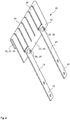
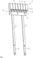
- FIG. 14 is a perspective view of the first embodiment 20 of a fastening device according to the invention Fig. 1 shown.
- the grid securing section 22 can be formed from a metal sheet 40, such as a galvanized steel sheet.
- the securing units 26 are formed by cutting sheet metal tongues 42 on a longitudinal edge 34 of the metal sheet 40 and bending end sections 44 of the sheet metal tongues 42.
- the individual sheet metal tongues 42 are milled or cut, for example, on the longitudinal edge 34.
- These sheet metal tongues 42 are bent at their end sections and thus formed into hook-shaped securing units 32.
- the end sections 44 can be formed parallel to the sheet metal tongues 42.
- the area of the end sections 44 can have a length of at least 35 mm so that the end section 44 of the sheet metal tongues 44 cannot be bent open when the fastening device 20 is installed.
- the grid securing section is connected to a tension securing section 24 via a releasable connection 28.
- screws, safety screws, bolts or rivets can be used as the detachable connection 28.
- the releasable connections 28 can preferably only be removed by means of a special tool.
- the train securing section 24 can be made in one piece or in several pieces.
- the tension protection section 24 can be formed as a sheet metal or profile component, as well as from a chain-like, rope-like or rod-like construction.
- a further protective structure can be provided around the detachable connection 28, which can prevent access to the grid and thus the detachment of the connection 28 by unauthorized persons.
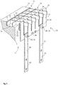
- FIG. 3 shows the first embodiment 20 of the fastening device in the installed state.
- a first component 10 is shown, comprising a lattice structure 12 and a frame 17 of the lattice structure 12, which in the edge region rests with the frame 17 on a support edge 19 of a second component 18.
- the lattice structure comprises individual meshes 14, which are formed by several rod sections 16, mostly by four rod sections 16.
- the first component 10 can form a grating for a light shaft 11 and the second component 18 the outer wall of the light shaft 11.
- the fastening device 20 is formed from a grid securing section 22 and a tension securing section 24.
- the grid securing section 22 is connected to the first component 10, which comprises a grid structure 12.
- the lattice securing section 22 comprises several securing units 26.
- the securing units 26 enclose with their end regions 30 individual rod sections 16 of the lattice structure 12.
- the securing units 26 comprise individual rod sections 16 of a contiguous row of rod sections.
- the width b of each securing unit 26 is adapted to the width of the rod sections 16 in the embodiment shown. This makes it almost impossible to sever the rod sections 16 which are enclosed by the hook-shaped securing unit 32.
- the grid securing section 22 is connected to the tension securing section 24 via a releasable connection 28.
- the tension securing section 24 can be fixed in its end region 46 on the second component 18 via bolt anchors (not shown).
- two fastening devices 20 can be attached to two opposite shaft walls of the light shaft 11.
- the number of securing units 26 can be adapted to the number of meshes 14 of the lattice structure 12 of the first component 10.
- a width of the lattice structure 12 of approximately 30 cm can be adequately secured with two fastening devices 20, each with eight securing units 26 with a width b of 29 mm each.
- the number of rod sections 16 to be cut in the event of unauthorized removal of the lattice structure 12 from the fastening device 20 is: number of securing units x 2 + 4.
- the lower edge of the lattice securing section 22 is provided with two mirror-inverted hook-shaped recesses 48 in which, for example, one or two traction safety chains or traction safety ropes can be suspended in order to fasten the lattice securing section.
- the fastening hooks 48 can be used in addition or as an alternative to the shown tension protection sections 24, which are designed in the form of flat bars or flat connectors, for tension protection of the grid protection section 22.
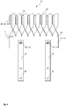
- Fig. 4 is a perspective view of another embodiment 20 of the invention shown.
- the fastening device 20 is designed in two parts, comprising a lattice securing section 22 and a tension securing section 24.
- the lattice securing section 22 comprises several securing units 26.
- the securing units 26 are arranged rotated by an angle ⁇ with respect to the base body of the lattice securing section 22.
- the longitudinal edges 34 of the fuse units 26 thus do not run in a line in the embodiment shown, but rather parallel to one another.
- the securing units 26 can encompass not only a contiguous row of longitudinal or transverse rod sections 16, but also longitudinal or transverse rod sections 16 running parallel. This can be of particular advantage if the fastening options in the light shaft 11 are not sufficient or are only available at a less than optimal location.
- the grid securing section 22 can be hung diagonally into a grid structure 12. With such an arrangement, a fastening device 20 can be sufficient for securing a first component 10 of a light shaft 11.
- the grid securing section 22 of the fastening device 20 can also have far more than seven securing units 26.
- each securing unit has a different angle ⁇ in order to be able to grip around corresponding rod sections.
- the angles can be adjusted during assembly.
- a tapering of the connection area of the fuse unit can be provided, which makes it easier to bend the fuse unit.
- Fig. 5 shows in perspective another embodiment of a fastening device 20 according to the invention.
- the grid securing section 22 and the tension securing section 24 are designed in one piece in the form of a single component.
- the fastening device 20 comprises several securing units 26 in the lattice securing section 22 and an end region 46 in the tension securing section 24 for fixing to a component.
- the end area can, for example, be fastened to the second component 18 in the light shaft 11 at several positions.
- the end area 46 is arranged in a step-like manner in a plane offset from the grid securing section 22. This prevents the end region 46 from being able to be reached from a position above the grid securing section.
- the fastening of the end region 46 to a component after the fastening device 20 has been installed in a light shaft 11 or the like cannot be released or removed by unauthorized persons.
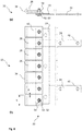
- Fig. 6 shows a fastening device 20 according to the invention in a side view Figure 6a as well as in cross section, Figure 6b .
- the fastening device 20 comprises a lattice securing section 22 and a tension securing section 24.
- the lattice securing section 22 comprises a plurality of securing units 26 which are not formed in one piece with the base body 23 of the lattice securing section 22.
- the securing units 26 are connected to the base body 23 of the grid securing section 22 with safety screws 50 or screws 52.
- These safety screws 50 or screws 52 which are fastened with shear nuts 54, represent a difficult-to-dismantle connection between the fuse units 26 and the base body 23 of the grid fuse section 22.
- the fuse units 26 run into the end region 30 in a hook-shaped 32.
- the hook end 30 runs parallel to the base body 23 of the grid securing section 22.
- the grid securing section 22 includes seven securing units 26, but embodiments with more or fewer securing units 26 are also possible.
- the longitudinal edges 34 of each fuse unit 26 form a line, so that the securing units 26 can encompass a number of contiguous longitudinal or transverse rod sections 16.
- the fuse units 26 have a width b, which corresponds to the width of a rod section, and are arranged at a distance d from one another.
- the grid securing section 22 can be formed from a metal sheet 40, in particular from a galvanized steel sheet.
- the grid securing section 22 and the train securing section 24 are connected to one another.
- the train securing section 24 can be formed, for example, by a rod-like, rope-like, profile-like or chain-like component.
- the tension protection section 24 can be connected in the end area 46 to a second component via bolt anchors (not shown) or the like.
- the tension protection section 24 can be designed in one piece or also in several pieces.
- FIG. 13 is a perspective view of the embodiment from FIG Fig. 6 a fastening device 20 according to the invention is shown.
- FIGs. 8a and 8b a fuse unit 26 and a base element 23 of the grid fuse section 22 are shown as individual elements.
- the illustrations each show a side view and a cross-sectional illustration.
- Figure 8a shows a securing unit 26 in the form of a flat hook.
- the end region 30 of the securing unit 26 runs parallel to the remaining region of the securing unit at a distance t2.
- the distance t2 is 5 mm, but can also be made larger or smaller.
- the longitudinal edge 34 is flat.
- the securing unit 26 comprises a borehole 64 which is used to attach the safety screws 50 or screws 52 with the tear-off nut 54.
- Figure 8b shows a base plate 23 of the grid securing section 22 with a plurality of boreholes 62 for attaching a plurality of securing units 26.
- the boreholes 62 are designed as elongated holes in order to enable the securing units 26 to be adjusted.
- the base element 23 likewise comprises three boreholes 66 for fixing the tension protection section (not shown).
- the train securing section 24 can also be anchored directly with the securing units 26 in a bore 62.
- the outer dimensions of the base plate 23 can be 220 mm ⁇ 40 mm.
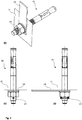
- FIGs. 9a to 9c show the bolt anchor 56 for fastening the tension protection section 24 to a wall of the light shaft 11 in three views.
- Figure 9a shows a three-dimensional view of the bolt anchor 56.
- the bolt anchor has a split pin hole with a clamping sleeve 61 passed through.
- the clamping sleeve 61 protrudes laterally with respect to the thread of the bolt anchor 56.
- the clamping sleeve 61 must therefore be removed with two hands using a hammer and a pin punch.
- the nut of the bolt anchor 56 can then be removed and the tension locking section 24 dismantled.
- the bolt anchor 56 per se is not released by turning the nut, but remains in the wall of the light shaft 11.
- the Figure 9b shows a view of the bolt anchor 56 from a view from the direction of the tension protection section.
- Figure 9c shows a side view of the built-in bolt anchor 56 in a wall of the light shaft 11, the light shaft 11 being shown in section.
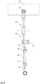
- Fig. 10 shows a train protection section 24 with a device for tensioning and fixing a certain length of the train protection section 24.
- the train securing section 24 consists of a chain which is connected to the base body 23 of the grid securing section 22 by a safety screw 50. At the other end, the chain is anchored in a wall of the light shaft (not shown), for example by means of a heavy-duty dowel (not shown).
- a long nut 68 is attached between this anchoring in a wall of the light shaft and the chain, an eyebolt 70 being screwed into both ends of the long nut 68.
- This eyebolt 70 is screwed to a tear-off nut 54 each in such a way that the tear-off nut 54 functions as a lock nut and fixes the eyebolt 70 relative to the long nut 68 so that it cannot rotate.
- the second eyebolt 70 is also fastened to the chain in the illustration by a shear nut 54.
- the long nut 68 including eye bolts 70 and shear nuts 54 can also be mounted between two chain sections.
Landscapes
- Engineering & Computer Science (AREA)
- Architecture (AREA)
- Civil Engineering (AREA)
- Structural Engineering (AREA)
- Business, Economics & Management (AREA)
- Emergency Management (AREA)
- Connection Of Plates (AREA)
- Sewage (AREA)
Claims (13)
- Dispositif de fixation (20) pour fixer un premier composant (10) présentant une structure réticulaire (12), comprenant une pluralité de mailles (14) délimitées par des sections de barres (16), à un second composant (18), sachant que le premier composant (10) est une grille et que le second composant (18) est un puits de lumière (11), sachant que le dispositif de fixation (20) comprend une section de fixation de grille (22) destinée à relier le dispositif de fixation (20) à la structure réticulaire (12) et une section de blocage de traction (24) destinée à relier le dispositif de fixation (20) au second composant (18), sachant que la section de fixation de grille (22) est formée d'un élément ou de plusieurs, sachant que la section de fixation de grille (22) présente au moins trois à dix, notamment sept ou huit unités de fixation (26) qui sont reliées à un corps de base (23) de la section de fixation de grille (22) de manière détachable et/ou non détachable, et sont notamment vissées, rivetées, soudées ou brasées et qui sont chacune reliables à une section de barre (16) de la structure réticulaire (12), sachant que la section de fixation de grille (22) est conçue sous forme de plaque et que les unités de fixation (26) sur un bord longitudinal (34) de la section de fixation de grille (22) sont formées et montées de sorte à pouvoir inclure, à la manière d'un peigne, plusieurs sections de barre (16) de la structure réticulaire (12) et que chaque unité de fixation (26) est conçue sous forme de crochet en U (32) à son extrémité (30) et enserre une section de barre (16) du premier composant (10) et que seulement les unités de fixation (26) à la manière d'un peigne sans composants plats sont visibles depuis une position située au-dessus du premier composant (10) si bien qu'une incidence de la lumière dans la structure réticulaire (12) n'est pas empêchée et que les unités de fixation (26) sont à peine perçues visuellement, et sachant qu'au moins trois sections de barre (16) de la structure réticulaire (12) sont entourées par les unités de fixation (26).
- Dispositif de fixation (20) selon la revendication 1, caractérisé en ce qu'au moins une unité de fixation (26), de préférence au moins deux unités de fixation (26), avec respectivement au moins une vis de sûreté (50) ou une vis (52), sont fixées en association avec un écrou de rupture (54) ou une vis de rupture (53) sur le corps de base (23) de la section de fixation de grille (22).
- Dispositif de fixation (20) selon une des revendications précédentes, caractérisé en ce que la section de fixation de grille (22) et la section de blocage de traction (24) sont formées à partir de composants séparés.
- Dispositif de fixation (20) selon la revendication 3, caractérisé en ce que la section de fixation de grille (22) et ladite au moins une section de blocage de traction (24) sont reliées l'une à l'autre par un raccord (28) par liaison de force et non détachable sans outil, notamment un raccord vissé ou riveté (38).
- Dispositif de fixation (20) selon la revendication 3, caractérisé en ce que la section de fixation de grille (22) présente au moins un évidement (48) conçu sous forme de crochet dans lequel il est possible de suspendre ladite au moins une section de blocage de traction (24).
- Dispositif de fixation (20) selon une des revendications 3 à 5, caractérisé en ce que la section de blocage de traction (24) est constituée d'un composant en forme de barre, de corde, de profilé ou de chaîne.
- Dispositif de fixation (20) selon une des revendications précédentes, caractérisé en ce que la section de blocage de traction (24) est réglable et fixable à une longueur au moyen d'au moins un écrou long (68) et d'au moins une vis à anneau (70).
- Dispositif de fixation (20) selon une des revendications précédentes, caractérisé en ce que la section de blocage de traction (24) est fixée à une paroi du puits de lumière (11), à l'aide d'au moins une cheville pour charge lourde (55), notamment un boulon d'ancrage (56) ou une vis à double filetage (57), avec ou sans trou de goupille (58), pour y faire passer une goupille élastique (61) ou une goupille fendue (60) ou une goupille fendue à ressort.
- Dispositif de fixation (20) selon une des revendications précédentes, caractérisé en ce qu'une zone de liaison (36) de l'unité de fixation (26) correspond à une longueur de section de barre b de la structure réticulaire (12) du premier composant (10).
- Dispositif de fixation (20) selon une des revendications précédentes, caractérisé en ce que la zone de liaison (36) de l'unité de fixation (26) présente une largeur b comprise entre 25 mm et 35 mm, de préférence 28 mm ou une largeur b comprise entre 6 mm et 9 mm, de préférence 7,5 mm et un écart d compris entre 3 mm et 6 mm, de préférence 4,5 mm par rapport à la zone de liaison (36) d'une unité de fixation (26) voisine.
- Dispositif de fixation (20) selon une des revendications précédentes, caractérisé en ce que la section de fixation de grille (22) est constituée d'une tôle métallique (40), notamment d'une tôle en acier galvanisé, sachant que dans le cas d'une conception de la section de fixation de grille (22) à un seul élément, les unités de blocage (26) sont conçues en entaillant des languettes de tôle (42) sur un bord longitudinal de la tôle métallique (40) et en déformant par flexion les sections terminales (44) des languettes de tôle (42).
- Dispositif de fixation (20) selon une des revendications précédentes, caractérisé en ce que les unités de blocage (26) sont tournées d'un angle α > 0°, notamment d'un angle α = 45° ou α = 90° par rapport à l'extension en forme de plaque de la section de fixation de grille (22).
- Dispositif de fixation (20) selon une des revendications précédentes, caractérisé en ce qu'au moins une unité de fixation (26) après avoir été assemblée à une barre (16), de préférence suspendue dans une section de barre (16) au moyen d'un boulon de sûreté ou d'une vis de sûreté (50) ou d'une vis (52) en association avec un écrou de rupture (54) ou une vis de rupture (53) sur la section de barre (16), peut être bloquée pour éviter un détachement, notamment un décrochement.
Applications Claiming Priority (2)
| Application Number | Priority Date | Filing Date | Title |
|---|---|---|---|
| DE201520101315 DE202015101315U1 (de) | 2015-03-13 | 2015-03-13 | Gitterrostsicherung |
| DE102015103758.0A DE102015103758A1 (de) | 2015-03-13 | 2015-03-13 | Gitterrostsicherung |
Publications (2)
| Publication Number | Publication Date |
|---|---|
| EP3067486A1 EP3067486A1 (fr) | 2016-09-14 |
| EP3067486B1 true EP3067486B1 (fr) | 2020-12-09 |
Family
ID=55650112
Family Applications (1)
| Application Number | Title | Priority Date | Filing Date |
|---|---|---|---|
| EP16160203.2A Active EP3067486B1 (fr) | 2015-03-13 | 2016-03-14 | Serrure pour grille |
Country Status (1)
| Country | Link |
|---|---|
| EP (1) | EP3067486B1 (fr) |
Cited By (1)
| Publication number | Priority date | Publication date | Assignee | Title |
|---|---|---|---|---|
| CN114876040A (zh) * | 2022-05-18 | 2022-08-09 | 无锡威而特金属制品有限公司 | 一种弧形钢格栅板及其使用方法 |
Families Citing this family (1)
| Publication number | Priority date | Publication date | Assignee | Title |
|---|---|---|---|---|
| DE102023005018A1 (de) * | 2023-12-06 | 2025-06-12 | Jungheinrich Aktiengesellschaft | Wärmestaublech zum Einsatz in Regallagern mit einer Mehrzahl von Lagerebenen |
Family Cites Families (12)
| Publication number | Priority date | Publication date | Assignee | Title |
|---|---|---|---|---|
| DE1890751U (de) | 1963-10-19 | 1964-04-09 | Gruenzweig & Hartmann | Verbindungs- und tragelement fuer gitterplatten. |
| DE7501257U (de) | 1975-01-17 | 1975-05-15 | Siegenia Frank Kg | Vorrichtung zur sicherung von gitterrosten |
| DE7638968U1 (de) | 1976-12-13 | 1977-04-14 | Kramer, Helga, 4150 Krefeld | Sicherung gegen abheben von kellergitterrosten |
| DE7713327U1 (de) | 1977-04-28 | 1977-11-03 | Hentschel, Karl, 6000 Frankfurt | Vorrichtung zur sicherung eines gitterrostes an einem kellerfenster |
| DE7738787U1 (de) | 1977-12-20 | 1978-05-03 | Wohllebe, Hans, 6056 Heusenstamm | Gitterrostsicherung |
| DE2849878C2 (de) | 1978-11-17 | 1986-08-21 | jobä Bäcker GmbH Fabrik für Gitterroste und Industrietreppen, 5940 Lennestadt | Einbruchsicherung für Gitterroste |
| DE2913112C2 (de) * | 1979-04-02 | 1982-03-18 | Fa. Aug. Winkhaus, 4404 Telgte | Sicherung für ein Abdeckgitter eines Kellerfensterschachts |
| DE3340106A1 (de) * | 1983-11-05 | 1985-05-15 | Lothar 7984 Wolpertswende Huber | Vorrichtung zum sichern eines eine schachtoeffnung abdeckenden gitterrostes gegen unbefugtes abheben |
| DE9002369U1 (de) * | 1990-03-01 | 1990-05-03 | Gebr. Sträb GmbH & Co, 7317 Wendlingen | Sicherungsvorrichtung für Schachtabdeckungen |
| DE4006321A1 (de) | 1990-03-01 | 1991-09-05 | Straeb Gmbh & Co Geb | Sicherungsvorrichtung fuer schachtabdeckungen |
| US5911664A (en) * | 1996-05-29 | 1999-06-15 | Advanced Industrial & Marine Services | Fastening system for securing composite gratings to structural members |
| CH699031B1 (de) | 2005-12-14 | 2010-01-15 | Beletto Ag | Sicherungsanordnung für einen Schacht mit einer Schachtabdeckung. |
-
2016
- 2016-03-14 EP EP16160203.2A patent/EP3067486B1/fr active Active
Non-Patent Citations (1)
| Title |
|---|
| None * |
Cited By (1)
| Publication number | Priority date | Publication date | Assignee | Title |
|---|---|---|---|---|
| CN114876040A (zh) * | 2022-05-18 | 2022-08-09 | 无锡威而特金属制品有限公司 | 一种弧形钢格栅板及其使用方法 |
Also Published As
| Publication number | Publication date |
|---|---|
| EP3067486A1 (fr) | 2016-09-14 |
Similar Documents
| Publication | Publication Date | Title |
|---|---|---|
| DE102018103897A1 (de) | Gerüst mit einer Aushebesicherungsvorrichtung und Verfahren zur Sicherung eines Gerüstbodens gegen Ausheben | |
| EP2685111A1 (fr) | Dispositif de serrage de connexion amovibles de deux pièces profilées | |
| WO2020049374A1 (fr) | Ferrure d'ajustage et système de support pour modules solaires | |
| EP3491205B1 (fr) | Élément de fixation | |
| EP2499311B1 (fr) | Grille de protection latérale et système de protection latérale | |
| CH698304B1 (de) | Drahtseilanker, insbesondere für Steinschlag- oder Lawinenschutzverbauungen. | |
| DE202015106689U1 (de) | Befestigungsvorrichtung für ein Gerüst oder eine Absturzsicherung und Gerüst oder Absturzsicherung damit | |
| EP3067486B1 (fr) | Serrure pour grille | |
| DE102021210759A1 (de) | Schutzzaunsystem und Verfahren zum Montieren eines Schutzzaunsystems | |
| DE202006018586U1 (de) | Anordnung zum Montieren von Solarmodulen | |
| DE202006003836U1 (de) | Deckenschalungssystem | |
| EP1232312A1 (fr) | Dispositif support pour objets longitudinaux accroches a un batiment, en particulier, gouttieres de drainage de toiture | |
| EP0872619A2 (fr) | Elément d'ajustement | |
| DE102019122106B3 (de) | Zaunerweiterungsvorrichtung | |
| EP2644807A1 (fr) | Système de mise en place de clôture | |
| DE3128505C2 (de) | Vorrichtung zur Verbindung einer hölzernen Fachwerksäule mit hölzernen Fachwerkträgern | |
| EP3402993B1 (fr) | Systeme de montage dote de rail de montage et ecrou de retenue en saillie | |
| DE202005011168U1 (de) | Vorrichtung zum Befestigen von Beschlägen | |
| EP0699260B1 (fr) | Systeme anti-chute a monter sur des toits | |
| DE202015101315U1 (de) | Gitterrostsicherung | |
| DE102015103758A1 (de) | Gitterrostsicherung | |
| WO1985001978A1 (fr) | Dispositif de fixation | |
| EP3322860B1 (fr) | Patte pour le transfert de charge dans l'isolation d'un bâtiment | |
| EP2434166B1 (fr) | Pince de support en tôle | |
| DE202006018108U1 (de) | Ankerschraube für Befestigungsklemmen an Profilschienen |
Legal Events
| Date | Code | Title | Description |
|---|---|---|---|
| PUAI | Public reference made under article 153(3) epc to a published international application that has entered the european phase |
Free format text: ORIGINAL CODE: 0009012 |
|
| AK | Designated contracting states |
Kind code of ref document: A1 Designated state(s): AL AT BE BG CH CY CZ DE DK EE ES FI FR GB GR HR HU IE IS IT LI LT LU LV MC MK MT NL NO PL PT RO RS SE SI SK SM TR |
|
| AX | Request for extension of the european patent |
Extension state: BA ME |
|
| STAA | Information on the status of an ep patent application or granted ep patent |
Free format text: STATUS: REQUEST FOR EXAMINATION WAS MADE |
|
| 17P | Request for examination filed |
Effective date: 20170314 |
|
| RBV | Designated contracting states (corrected) |
Designated state(s): AL AT BE BG CH CY CZ DE DK EE ES FI FR GB GR HR HU IE IS IT LI LT LU LV MC MK MT NL NO PL PT RO RS SE SI SK SM TR |
|
| STAA | Information on the status of an ep patent application or granted ep patent |
Free format text: STATUS: EXAMINATION IS IN PROGRESS |
|
| 17Q | First examination report despatched |
Effective date: 20190114 |
|
| REG | Reference to a national code |
Ref country code: DE Ref legal event code: R079 Ref document number: 502016011893 Country of ref document: DE Free format text: PREVIOUS MAIN CLASS: E04C0002420000 Ipc: E05B0065100000 |
|
| GRAP | Despatch of communication of intention to grant a patent |
Free format text: ORIGINAL CODE: EPIDOSNIGR1 |
|
| STAA | Information on the status of an ep patent application or granted ep patent |
Free format text: STATUS: GRANT OF PATENT IS INTENDED |
|
| RIC1 | Information provided on ipc code assigned before grant |
Ipc: E04C 2/42 20060101ALI20200602BHEP Ipc: E05B 65/10 20060101AFI20200602BHEP Ipc: E04F 17/06 20060101ALI20200602BHEP |
|
| INTG | Intention to grant announced |
Effective date: 20200630 |
|
| GRAS | Grant fee paid |
Free format text: ORIGINAL CODE: EPIDOSNIGR3 |
|
| GRAA | (expected) grant |
Free format text: ORIGINAL CODE: 0009210 |
|
| STAA | Information on the status of an ep patent application or granted ep patent |
Free format text: STATUS: THE PATENT HAS BEEN GRANTED |
|
| AK | Designated contracting states |
Kind code of ref document: B1 Designated state(s): AL AT BE BG CH CY CZ DE DK EE ES FI FR GB GR HR HU IE IS IT LI LT LU LV MC MK MT NL NO PL PT RO RS SE SI SK SM TR |
|
| REG | Reference to a national code |
Ref country code: GB Ref legal event code: FG4D Free format text: NOT ENGLISH |
|
| REG | Reference to a national code |
Ref country code: AT Ref legal event code: REF Ref document number: 1343617 Country of ref document: AT Kind code of ref document: T Effective date: 20201215 Ref country code: CH Ref legal event code: EP |
|
| REG | Reference to a national code |
Ref country code: DE Ref legal event code: R096 Ref document number: 502016011893 Country of ref document: DE |
|
| REG | Reference to a national code |
Ref country code: IE Ref legal event code: FG4D Free format text: LANGUAGE OF EP DOCUMENT: GERMAN |
|
| PG25 | Lapsed in a contracting state [announced via postgrant information from national office to epo] |
Ref country code: RS Free format text: LAPSE BECAUSE OF FAILURE TO SUBMIT A TRANSLATION OF THE DESCRIPTION OR TO PAY THE FEE WITHIN THE PRESCRIBED TIME-LIMIT Effective date: 20201209 Ref country code: FI Free format text: LAPSE BECAUSE OF FAILURE TO SUBMIT A TRANSLATION OF THE DESCRIPTION OR TO PAY THE FEE WITHIN THE PRESCRIBED TIME-LIMIT Effective date: 20201209 Ref country code: NO Free format text: LAPSE BECAUSE OF FAILURE TO SUBMIT A TRANSLATION OF THE DESCRIPTION OR TO PAY THE FEE WITHIN THE PRESCRIBED TIME-LIMIT Effective date: 20210309 Ref country code: GR Free format text: LAPSE BECAUSE OF FAILURE TO SUBMIT A TRANSLATION OF THE DESCRIPTION OR TO PAY THE FEE WITHIN THE PRESCRIBED TIME-LIMIT Effective date: 20210310 |
|
| PG25 | Lapsed in a contracting state [announced via postgrant information from national office to epo] |
Ref country code: BG Free format text: LAPSE BECAUSE OF FAILURE TO SUBMIT A TRANSLATION OF THE DESCRIPTION OR TO PAY THE FEE WITHIN THE PRESCRIBED TIME-LIMIT Effective date: 20210309 Ref country code: SE Free format text: LAPSE BECAUSE OF FAILURE TO SUBMIT A TRANSLATION OF THE DESCRIPTION OR TO PAY THE FEE WITHIN THE PRESCRIBED TIME-LIMIT Effective date: 20201209 Ref country code: LV Free format text: LAPSE BECAUSE OF FAILURE TO SUBMIT A TRANSLATION OF THE DESCRIPTION OR TO PAY THE FEE WITHIN THE PRESCRIBED TIME-LIMIT Effective date: 20201209 |
|
| PGFP | Annual fee paid to national office [announced via postgrant information from national office to epo] |
Ref country code: AT Payment date: 20210326 Year of fee payment: 6 |
|
| REG | Reference to a national code |
Ref country code: NL Ref legal event code: MP Effective date: 20201209 |
|
| PG25 | Lapsed in a contracting state [announced via postgrant information from national office to epo] |
Ref country code: HR Free format text: LAPSE BECAUSE OF FAILURE TO SUBMIT A TRANSLATION OF THE DESCRIPTION OR TO PAY THE FEE WITHIN THE PRESCRIBED TIME-LIMIT Effective date: 20201209 Ref country code: NL Free format text: LAPSE BECAUSE OF FAILURE TO SUBMIT A TRANSLATION OF THE DESCRIPTION OR TO PAY THE FEE WITHIN THE PRESCRIBED TIME-LIMIT Effective date: 20201209 |
|
| REG | Reference to a national code |
Ref country code: LT Ref legal event code: MG9D |
|
| PG25 | Lapsed in a contracting state [announced via postgrant information from national office to epo] |
Ref country code: SK Free format text: LAPSE BECAUSE OF FAILURE TO SUBMIT A TRANSLATION OF THE DESCRIPTION OR TO PAY THE FEE WITHIN THE PRESCRIBED TIME-LIMIT Effective date: 20201209 Ref country code: RO Free format text: LAPSE BECAUSE OF FAILURE TO SUBMIT A TRANSLATION OF THE DESCRIPTION OR TO PAY THE FEE WITHIN THE PRESCRIBED TIME-LIMIT Effective date: 20201209 Ref country code: PT Free format text: LAPSE BECAUSE OF FAILURE TO SUBMIT A TRANSLATION OF THE DESCRIPTION OR TO PAY THE FEE WITHIN THE PRESCRIBED TIME-LIMIT Effective date: 20210409 Ref country code: EE Free format text: LAPSE BECAUSE OF FAILURE TO SUBMIT A TRANSLATION OF THE DESCRIPTION OR TO PAY THE FEE WITHIN THE PRESCRIBED TIME-LIMIT Effective date: 20201209 Ref country code: CZ Free format text: LAPSE BECAUSE OF FAILURE TO SUBMIT A TRANSLATION OF THE DESCRIPTION OR TO PAY THE FEE WITHIN THE PRESCRIBED TIME-LIMIT Effective date: 20201209 Ref country code: SM Free format text: LAPSE BECAUSE OF FAILURE TO SUBMIT A TRANSLATION OF THE DESCRIPTION OR TO PAY THE FEE WITHIN THE PRESCRIBED TIME-LIMIT Effective date: 20201209 Ref country code: LT Free format text: LAPSE BECAUSE OF FAILURE TO SUBMIT A TRANSLATION OF THE DESCRIPTION OR TO PAY THE FEE WITHIN THE PRESCRIBED TIME-LIMIT Effective date: 20201209 |
|
| PG25 | Lapsed in a contracting state [announced via postgrant information from national office to epo] |
Ref country code: PL Free format text: LAPSE BECAUSE OF FAILURE TO SUBMIT A TRANSLATION OF THE DESCRIPTION OR TO PAY THE FEE WITHIN THE PRESCRIBED TIME-LIMIT Effective date: 20201209 |
|
| PGFP | Annual fee paid to national office [announced via postgrant information from national office to epo] |
Ref country code: CH Payment date: 20210422 Year of fee payment: 6 |
|
| REG | Reference to a national code |
Ref country code: DE Ref legal event code: R097 Ref document number: 502016011893 Country of ref document: DE |
|
| PG25 | Lapsed in a contracting state [announced via postgrant information from national office to epo] |
Ref country code: IS Free format text: LAPSE BECAUSE OF FAILURE TO SUBMIT A TRANSLATION OF THE DESCRIPTION OR TO PAY THE FEE WITHIN THE PRESCRIBED TIME-LIMIT Effective date: 20210409 |
|
| PLBE | No opposition filed within time limit |
Free format text: ORIGINAL CODE: 0009261 |
|
| STAA | Information on the status of an ep patent application or granted ep patent |
Free format text: STATUS: NO OPPOSITION FILED WITHIN TIME LIMIT |
|
| PG25 | Lapsed in a contracting state [announced via postgrant information from national office to epo] |
Ref country code: MC Free format text: LAPSE BECAUSE OF FAILURE TO SUBMIT A TRANSLATION OF THE DESCRIPTION OR TO PAY THE FEE WITHIN THE PRESCRIBED TIME-LIMIT Effective date: 20201209 Ref country code: AL Free format text: LAPSE BECAUSE OF FAILURE TO SUBMIT A TRANSLATION OF THE DESCRIPTION OR TO PAY THE FEE WITHIN THE PRESCRIBED TIME-LIMIT Effective date: 20201209 Ref country code: IT Free format text: LAPSE BECAUSE OF FAILURE TO SUBMIT A TRANSLATION OF THE DESCRIPTION OR TO PAY THE FEE WITHIN THE PRESCRIBED TIME-LIMIT Effective date: 20201209 |
|
| 26N | No opposition filed |
Effective date: 20210910 |
|
| GBPC | Gb: european patent ceased through non-payment of renewal fee |
Effective date: 20210314 |
|
| PG25 | Lapsed in a contracting state [announced via postgrant information from national office to epo] |
Ref country code: DK Free format text: LAPSE BECAUSE OF FAILURE TO SUBMIT A TRANSLATION OF THE DESCRIPTION OR TO PAY THE FEE WITHIN THE PRESCRIBED TIME-LIMIT Effective date: 20201209 Ref country code: ES Free format text: LAPSE BECAUSE OF FAILURE TO SUBMIT A TRANSLATION OF THE DESCRIPTION OR TO PAY THE FEE WITHIN THE PRESCRIBED TIME-LIMIT Effective date: 20201209 Ref country code: SI Free format text: LAPSE BECAUSE OF FAILURE TO SUBMIT A TRANSLATION OF THE DESCRIPTION OR TO PAY THE FEE WITHIN THE PRESCRIBED TIME-LIMIT Effective date: 20201209 |
|
| REG | Reference to a national code |
Ref country code: BE Ref legal event code: MM Effective date: 20210331 |
|
| PG25 | Lapsed in a contracting state [announced via postgrant information from national office to epo] |
Ref country code: IE Free format text: LAPSE BECAUSE OF NON-PAYMENT OF DUE FEES Effective date: 20210314 Ref country code: FR Free format text: LAPSE BECAUSE OF NON-PAYMENT OF DUE FEES Effective date: 20210331 Ref country code: GB Free format text: LAPSE BECAUSE OF NON-PAYMENT OF DUE FEES Effective date: 20210314 Ref country code: LU Free format text: LAPSE BECAUSE OF NON-PAYMENT OF DUE FEES Effective date: 20210314 |
|
| PG25 | Lapsed in a contracting state [announced via postgrant information from national office to epo] |
Ref country code: IS Free format text: LAPSE BECAUSE OF FAILURE TO SUBMIT A TRANSLATION OF THE DESCRIPTION OR TO PAY THE FEE WITHIN THE PRESCRIBED TIME-LIMIT Effective date: 20210409 |
|
| PG25 | Lapsed in a contracting state [announced via postgrant information from national office to epo] |
Ref country code: BE Free format text: LAPSE BECAUSE OF NON-PAYMENT OF DUE FEES Effective date: 20210331 |
|
| REG | Reference to a national code |
Ref country code: CH Ref legal event code: PL |
|
| REG | Reference to a national code |
Ref country code: AT Ref legal event code: MM01 Ref document number: 1343617 Country of ref document: AT Kind code of ref document: T Effective date: 20220314 |
|
| PG25 | Lapsed in a contracting state [announced via postgrant information from national office to epo] |
Ref country code: LI Free format text: LAPSE BECAUSE OF NON-PAYMENT OF DUE FEES Effective date: 20220331 Ref country code: CH Free format text: LAPSE BECAUSE OF NON-PAYMENT OF DUE FEES Effective date: 20220331 Ref country code: AT Free format text: LAPSE BECAUSE OF NON-PAYMENT OF DUE FEES Effective date: 20220314 |
|
| PG25 | Lapsed in a contracting state [announced via postgrant information from national office to epo] |
Ref country code: HU Free format text: LAPSE BECAUSE OF FAILURE TO SUBMIT A TRANSLATION OF THE DESCRIPTION OR TO PAY THE FEE WITHIN THE PRESCRIBED TIME-LIMIT; INVALID AB INITIO Effective date: 20160314 |
|
| PG25 | Lapsed in a contracting state [announced via postgrant information from national office to epo] |
Ref country code: CY Free format text: LAPSE BECAUSE OF FAILURE TO SUBMIT A TRANSLATION OF THE DESCRIPTION OR TO PAY THE FEE WITHIN THE PRESCRIBED TIME-LIMIT Effective date: 20201209 |
|
| PG25 | Lapsed in a contracting state [announced via postgrant information from national office to epo] |
Ref country code: MK Free format text: LAPSE BECAUSE OF FAILURE TO SUBMIT A TRANSLATION OF THE DESCRIPTION OR TO PAY THE FEE WITHIN THE PRESCRIBED TIME-LIMIT Effective date: 20201209 |
|
| PG25 | Lapsed in a contracting state [announced via postgrant information from national office to epo] |
Ref country code: MT Free format text: LAPSE BECAUSE OF FAILURE TO SUBMIT A TRANSLATION OF THE DESCRIPTION OR TO PAY THE FEE WITHIN THE PRESCRIBED TIME-LIMIT Effective date: 20201209 |
|
| PGFP | Annual fee paid to national office [announced via postgrant information from national office to epo] |
Ref country code: DE Payment date: 20250425 Year of fee payment: 10 |
|
| PG25 | Lapsed in a contracting state [announced via postgrant information from national office to epo] |
Ref country code: TR Free format text: LAPSE BECAUSE OF FAILURE TO SUBMIT A TRANSLATION OF THE DESCRIPTION OR TO PAY THE FEE WITHIN THE PRESCRIBED TIME-LIMIT Effective date: 20201209 |