EP2462046B1 - Appareil de traitement des pièces - Google Patents
Appareil de traitement des pièces Download PDFInfo
- Publication number
- EP2462046B1 EP2462046B1 EP10745453.0A EP10745453A EP2462046B1 EP 2462046 B1 EP2462046 B1 EP 2462046B1 EP 10745453 A EP10745453 A EP 10745453A EP 2462046 B1 EP2462046 B1 EP 2462046B1
- Authority
- EP
- European Patent Office
- Prior art keywords
- tower
- handled
- parts
- telescopic column
- handling device
- Prior art date
- Legal status (The legal status is an assumption and is not a legal conclusion. Google has not performed a legal analysis and makes no representation as to the accuracy of the status listed.)
- Not-in-force
Links
- 230000002779 inactivation Effects 0.000 claims description 2
- 230000001360 synchronised effect Effects 0.000 claims description 2
- 230000003028 elevating effect Effects 0.000 claims 1
- 238000010276 construction Methods 0.000 description 5
- 239000002184 metal Substances 0.000 description 4
- 238000005096 rolling process Methods 0.000 description 2
Images


Classifications
-
- B—PERFORMING OPERATIONS; TRANSPORTING
- B66—HOISTING; LIFTING; HAULING
- B66C—CRANES; LOAD-ENGAGING ELEMENTS OR DEVICES FOR CRANES, CAPSTANS, WINCHES, OR TACKLES
- B66C13/00—Other constructional features or details
- B66C13/04—Auxiliary devices for controlling movements of suspended loads, or preventing cable slack
- B66C13/08—Auxiliary devices for controlling movements of suspended loads, or preventing cable slack for depositing loads in desired attitudes or positions
Definitions
- the present invention is used in the metal construction field and relates to a parts handling device, particularly used for lifting and rotating up to 360° longitudinal parts such as profiles with different sections.
- the parts handling device allows for the execution of metal and mechanical construction works using long profiled parts, without overhead cranes help, in a safe and ergonomic manner to the operator.
- Parts handling devices for longitudinal parts are known from prior art. For instance, reference must be made to the devices disclosed in Patent Applications DE102004031206 and DE19962203 .
- DE102004031206 Patent Application refers to a device comprising a chain and two retaining arms carrying a load. Rolls are arranged at the retaining arms for deviating the chain, where the distance between the rolls is adjustable with each other.
- the device described in this invention also comprises further rolls also provided for deviating the chain, said rolls being located at opposite ends of the retaining arms.
- the retaining arms are rotatably designed at a rotating axis.
- DE19962203 Patent Application refers to a load rotating device having a rolling section provided with a belt, a chain, or a cable which is passed around at least one roller and used for supporting the load. Said rolling section is secured to one end of a lever arm, coupled to a support arm at the other end, said support arm being mounted on a base for supporting the load rotating device on the ground. Such a device is also disclosed in document DE 3917545 .
- the present invention relates to a parts handling device, particularly for longitudinal parts elevation and rotation up to 360°.
- the parts handling device comprises at least one tower, the main tower, and a secondary tower used as satellite tower relative to the main tower.
- the main tower controls the elevation and rotation of the part to be handled in the parts handling device.
- the parts handling device is used in the metal construction field, for assistance in welded construction, mould assembling and all kind of longitudinal parts handling, allowing for the execution of metal and mechanical construction works using long profiled parts, without overhead cranes help.
- the parts handling device is characterized by the elevation and rotation up to 360° of the parts to be handled, thus providing access to any section of the parts without forcing the operator to assume wrong or unsafe working positions.
- the parts handling device permits the parts to be handled to take various positions, due to the articulated loading arm and a completely open front access, allowing for a quick and safe loading and unloading of the parts to be handled.
- both towers such as a hydraulically adjustable telescopic column with a maximum travel of 800 mm, which may be changed as needed and as a function of the size of the parts to be handled; a height adjustable trestle for supporting the parts, thus achieving an optimal working position which meets the so desired ergonomic principles in workplaces for fitness of the work to the worker; a fixed loading arm at the upper part of the telescopic column; and a pulley coupled to the fixed loading arm where a belt runs giving support and rotating the part to be handled.
- the above mentioned hydraulic device comprises a load limitation system that prevents any movement if the part to be handled has a higher weight than the lifting force for which the parts handling device is designed.
- the rotation of the parts to be handled is executed through belts suspended from the pulleys, which are coupled to the respective fixed arms of the main tower and satellite tower.
- the pulley located at the main tower is connected to a gear-motor allowing for different pulley rotation speeds, the same happening with the belt supporting the part to be handled.
- a gear-motor allowing for different pulley rotation speeds, the same happening with the belt supporting the part to be handled.
- the pulley runs freely actuated by the belt, and together with the other pulley located in the main tower which is coupled to the gear-motor that drives the belt and hence rotates the part to be handled.
- the present invention refers to a parts handling device, particularly used in lifting and rotation of longitudinal parts such as metallic profiles with different sections.
- the device comprises at least one tower, the main tower (1), and a satellite tower (2) linked by a hydraulic device sleeve (not shown in the Figures), presenting each tower a support base (4, 13).
- the main tower (1) and the satellite tower (2) have several identical components, such as a telescopic column (5, 14), a trestle (6, 15) and a fixed loading arm (9, 16), a pulley (7, 17) where a belt (8, 18) runs giving support and rotating the part to be handled.
- One function of the main tower (1) is controlling the elevation and rotation of the part to be handled in the parts handling device, including elevation of the telescopic column (5) and of the telescopic column (14) of the satellite tower (2), and rotation of the belt (8) and of the belt (18) of the satellite tower (2), the latter being moved by the action of the part itself, so as to move the part to be handled in a synchronized way.
- the height of the telescopic columns (5, 14) can be adjusted through a hydraulic device (12) having a variable course, which can be changed as needed and depending on the size of the parts to be handled, and having a load limitation system that prevents any movement if the part to be handled has a higher weight than the lifting force for which the towers (1, 2) are designed.
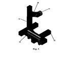
- the height of the trestle (6) and of the trestle (15), shown in Figures 2 and 4 and in Figure 3 respectively, is manually adjustable giving support to the part to be handled.
- a pulley (7, 17) is coupled to the fixed loading arm (9, 16), where a belt (8, 18) runs giving support and rotating the part to be handled, as shown in Figure 1 .
- the main tower (1) also includes a gear-motor (10) with a speed variator allowing for multiple rotation speeds of the pulley (7); a hydraulic device (12) for moving the telescopic column (5) and the telescopic column (14); an articulated loading arm (3) located at the upper part of the telescopic column (5) which performs a 270° rotation horizontally around the telescopic column (5), on which an electric winch (11) is coupled and can be manually moved along the loading arm (3) to help the positioning of the parts to be welded at the top and/or the sides of the handled part.
- a gear-motor (10) with a speed variator allowing for multiple rotation speeds of the pulley (7)
- a hydraulic device (12) for moving the telescopic column (5) and the telescopic column (14)
- an articulated loading arm (3) located at the upper part of the telescopic column (5) which performs a 270° rotation horizontally around the telescopic column (5), on which an electric winch (11) is coupled and
- the articulated loading arm (3) represented in Figures 2 and 4 , performs a 270° rotation horizontally around the telescopic column (5), on which an electric winch (11) is coupled and can be manually moved along the loading arm (3) to help the positioning of the parts to be welded at the top and/or the sides of the handled part.
- the satellite tower (2) ( Figure 1 ) includes a pulley (17) which runs freely actuated by the belt (18), and together with the other pulley (7), the latter being coupled to a gear-motor (10) that drives the belt (8) and hence rotates the part to be handled.
- Total stability and control in each one of the towers (1, 2) is achieved by lifting the part to be handled in a strictly horizontal manner and by load control during this movement, since during the elevation the part to be handled always keeps the same distance from the main tower (1) and satellite tower (2), thus avoiding any collisions with either of them.
- the tower (1) in the device described in this invention can move the parts to be handled autonomously and independently from the satellite tower (2), through inactivation of the hydraulic device sleeve (not shown in the Figures).
Landscapes
- Engineering & Computer Science (AREA)
- Mechanical Engineering (AREA)
- Jib Cranes (AREA)
- Load-Engaging Elements For Cranes (AREA)
Claims (6)
- Un dispositif de manipulation de pièces, utilisé en particulier pour l'élévation et la rotation jusqu'à 360° de pièces, comprenant au moins une tour, la tour principale (1) et une tour satellite (2) reliées par une manche d'un dispositif hydraulique, chaque tour disposant d'une base de support (4, 13), caractérisé en ce que :chacune des tours, la tour principale (1) et la tour satellite (2), comprend :- une colonne télescopique (5, 14) dont la hauteur peut être réglée au moyen d'un dispositif hydraulique (12) ayant un cours variable, qui peut être altéré selon les nécessités et en fonction de la dimension des pièces à être manipulées, et ayant un système de limitation de charge qui empêche tout mouvement si la pièce à être manipulée a un poids supérieur à la force d'élévation pour laquelle les tours (1, 2) sont conçues ;- un chevalet (6, 15) dont la hauteur peut être réglée manuellement afin d'appuyer la pièce à être manipulée ;- un bras de charge fixe (9, 16) couplé à la partie supérieure de la colonne télescopique (5, 14), sur lequel est montée une poulie (7, 17) où passe une ceinture (8, 18) pour appuyer et faire tourner la pièce à être manipulée.
- Un dispositif de manipulation de pièces selon la revendication 1, caractérisé en ce que ladite tour principale (1) comprend également :- un moto-réducteur (10) avec un variateur de vitesse qui permet des vitesses de rotation multiples de la poulie (7) ;- un dispositif hydraulique (12) situé dans la tour (1) pour assurer le mouvement de la colonne télescopique (5) et de la colonne télescopique (14) au moyen d'une manche d'un dispositif hydraulique qui relie les deux tours (1, 2) ; et- un bras de charge articulé (3) situé dans la partie supérieure de la colonne télescopique (5), qui réalise une rotation de 270° horizontalement autour de la colonne télescopique (5), et sur lequel est couplé un treuil électrique (11) qui peut être déplacé manuellement le long du bras de charge (3) pour aider le positionnement des pièces à être soudées sur le dessus et/ou les côtés de la pièce qui est manipulée.
- Un dispositif de manipulation de pièces selon les revendications précédentes, caractérisé en ce que le dispositif hydraulique (12) de la tour principale (1) commande le mouvement de la colonne télescopique (14) de la tour satellite (2) et commande la rotation de la ceinture (18) de la tour satellite (2), au moyen de l'action de la pièce suspendue de la ceinture (8), afin de déplacer de façon synchronisée la pièce qui est manipulée.
- Un dispositif de manipulation de pièces selon les revendications précédentes, caractérisé en ce que la poulie (17) se déplace librement dans la tour satellite (2) par l'action de la ceinture (18), et simultanément avec l'autre poulie (7) qui est couplée à un moto-réducteur (10) qui actionne la ceinture (8) et donc fait tourner la pièce à être manipulée.
- Un dispositif de manipulation de pièces selon les revendications précédentes, caractérisé en ce que l'élévation de la pièce à être manipulée, dans la colonne télescopique (5) et la colonne télescopique (14), de façon parfaitement horizontale et tout en maintenant le contrôle de la charge pendant le mouvement, permet le contrôlé total de la stabilité de chacune des tours (1, 2), étant donné que pendant tout le cycle de fonctionnement, la pièce à être manipulée maintient toujours la même distance des tours (1, 2), en évitant des collisions avec elles.
- Un dispositif de manipulation de pièces selon les revendications précédentes, caractérisé en ce que dans le cas de pièces à être manipulées de petites dimensions, la tour (1) peut déplacer lesdites pièces à être manipulées de façon autonome et indépendante de la tour (2), au moyen de la désactivation de la manche d'un dispositif hydraulique.
Applications Claiming Priority (2)
| Application Number | Priority Date | Filing Date | Title |
|---|---|---|---|
| PT10470709A PT104707A (pt) | 2009-08-04 | 2009-08-04 | Equipamento para movimentação de peças |
| PCT/PT2010/000031 WO2011016740A1 (fr) | 2009-08-04 | 2010-07-14 | Appareil de traitement des pièces |
Publications (2)
| Publication Number | Publication Date |
|---|---|
| EP2462046A1 EP2462046A1 (fr) | 2012-06-13 |
| EP2462046B1 true EP2462046B1 (fr) | 2013-07-31 |
Family
ID=43016497
Family Applications (1)
| Application Number | Title | Priority Date | Filing Date |
|---|---|---|---|
| EP10745453.0A Not-in-force EP2462046B1 (fr) | 2009-08-04 | 2010-07-14 | Appareil de traitement des pièces |
Country Status (4)
| Country | Link |
|---|---|
| EP (1) | EP2462046B1 (fr) |
| ES (1) | ES2433232T3 (fr) |
| PT (1) | PT104707A (fr) |
| WO (1) | WO2011016740A1 (fr) |
Families Citing this family (2)
| Publication number | Priority date | Publication date | Assignee | Title |
|---|---|---|---|---|
| DE202012005764U1 (de) | 2012-06-13 | 2012-08-06 | Hans-Ulrich Hedicke | Vorrichtung zum Wenden und Drehen von Lasten |
| DE102012011734A1 (de) | 2012-06-13 | 2013-12-19 | Hans-Ulrich Hedicke | Vorrichtung zum Wenden und Drehen von Lasten |
Family Cites Families (3)
| Publication number | Priority date | Publication date | Assignee | Title |
|---|---|---|---|---|
| DE3917545A1 (de) * | 1989-05-30 | 1989-11-23 | Petry Stahlbau Gmbh | Vorrichtung und verfahren zum wenden von lasten |
| DE19962203C2 (de) | 1999-12-22 | 2002-09-26 | Temme Stahlbau Gmbh | Vorrichtung zum Wenden von Lasten |
| DE102004031206A1 (de) | 2004-06-28 | 2006-01-12 | Stierli-Bieger Ag | Vorrichtung zum Drehen und Wenden von Lasten |
-
2009
- 2009-08-04 PT PT10470709A patent/PT104707A/pt not_active IP Right Cessation
-
2010
- 2010-07-14 WO PCT/PT2010/000031 patent/WO2011016740A1/fr not_active Ceased
- 2010-07-14 ES ES10745453T patent/ES2433232T3/es active Active
- 2010-07-14 EP EP10745453.0A patent/EP2462046B1/fr not_active Not-in-force
Also Published As
| Publication number | Publication date |
|---|---|
| EP2462046A1 (fr) | 2012-06-13 |
| ES2433232T3 (es) | 2013-12-10 |
| WO2011016740A8 (fr) | 2012-04-19 |
| WO2011016740A1 (fr) | 2011-02-10 |
| PT104707A (pt) | 2011-02-04 |
Similar Documents
| Publication | Publication Date | Title |
|---|---|---|
| AU2016386566B2 (en) | Gondola device | |
| EP1974109B1 (fr) | Dispositif donnant acces a une structure se trouvant au-dessus du niveau du sol | |
| EP2949614B1 (fr) | Chariot | |
| US8671626B1 (en) | Apparatus and method for a drilling rig assembly | |
| CN205916923U (zh) | 风机塔筒内的维护工装 | |
| EP2828193B1 (fr) | Dispositif de levage de charge | |
| AU2013350006A1 (en) | Gripping apparatus for handling reinforcement cages for tower segments of a wind turbine | |
| JPS61136095A (ja) | 昇降装置 | |
| JPH11310396A (ja) | 移動式昇降作業台用垂直マストの横ジブ | |
| CN209601918U (zh) | 一种角度可调的吊具 | |
| CN205114818U (zh) | 一种翻转吊具用翻转机构及翻转吊具 | |
| EP2915768A1 (fr) | Grue-portail | |
| EP2462046B1 (fr) | Appareil de traitement des pièces | |
| KR200482680Y1 (ko) | 배관용 리프터 | |
| KR101016263B1 (ko) | 철골 구조의 볼트 체결을 위한 더블시저타입 이동 메니퓰레이터 로봇 | |
| CN106542444A (zh) | 一种建立在塔身回转的弯矩减少结构 | |
| EP3356278B2 (fr) | Agencement de levage permettant de soulever un composant de turbine d'éolienne | |
| CN207108405U (zh) | 移动式轻型顶升装置 | |
| KR100881807B1 (ko) | 더블 크레인 | |
| KR101834355B1 (ko) | 사절회전기구를 이용한 관절식 리프트 | |
| KR101363260B1 (ko) | 두 개 아암의 폭이 가변 가능한 이동식 곤도라 행거 | |
| KR20160113870A (ko) | 크레인에 장착되는 고소 작업 장치 | |
| JP7028635B2 (ja) | 水平ジブを備えた揚重装置 | |
| JP7042080B2 (ja) | 水平ジブを備えた揚重装置 | |
| JP2026048074A (ja) | 高所作業台及びそれを備えた高所作業ロボット |
Legal Events
| Date | Code | Title | Description |
|---|---|---|---|
| PUAI | Public reference made under article 153(3) epc to a published international application that has entered the european phase |
Free format text: ORIGINAL CODE: 0009012 |
|
| 17P | Request for examination filed |
Effective date: 20120424 |
|
| AK | Designated contracting states |
Kind code of ref document: A1 Designated state(s): AL AT BE BG CH CY CZ DE DK EE ES FI FR GB GR HR HU IE IS IT LI LT LU LV MC MK MT NL NO PL PT RO SE SI SK SM TR |
|
| R17P | Request for examination filed (corrected) |
Effective date: 20120227 |
|
| DAX | Request for extension of the european patent (deleted) | ||
| GRAP | Despatch of communication of intention to grant a patent |
Free format text: ORIGINAL CODE: EPIDOSNIGR1 |
|
| GRAS | Grant fee paid |
Free format text: ORIGINAL CODE: EPIDOSNIGR3 |
|
| GRAA | (expected) grant |
Free format text: ORIGINAL CODE: 0009210 |
|
| AK | Designated contracting states |
Kind code of ref document: B1 Designated state(s): AL AT BE BG CH CY CZ DE DK EE ES FI FR GB GR HR HU IE IS IT LI LT LU LV MC MK MT NL NO PL PT RO SE SI SK SM TR |
|
| REG | Reference to a national code |
Ref country code: GB Ref legal event code: FG4D Ref country code: CH Ref legal event code: EP |
|
| REG | Reference to a national code |
Ref country code: AT Ref legal event code: REF Ref document number: 624492 Country of ref document: AT Kind code of ref document: T Effective date: 20130815 |
|
| REG | Reference to a national code |
Ref country code: IE Ref legal event code: FG4D |
|
| REG | Reference to a national code |
Ref country code: DE Ref legal event code: R096 Ref document number: 602010009089 Country of ref document: DE Effective date: 20130926 |
|
| REG | Reference to a national code |
Ref country code: NL Ref legal event code: T3 |
|
| REG | Reference to a national code |
Ref country code: ES Ref legal event code: FG2A Ref document number: 2433232 Country of ref document: ES Kind code of ref document: T3 Effective date: 20131210 |
|
| REG | Reference to a national code |
Ref country code: AT Ref legal event code: MK05 Ref document number: 624492 Country of ref document: AT Kind code of ref document: T Effective date: 20130731 |
|
| REG | Reference to a national code |
Ref country code: LT Ref legal event code: MG4D |
|
| PG25 | Lapsed in a contracting state [announced via postgrant information from national office to epo] |
Ref country code: HR Free format text: LAPSE BECAUSE OF FAILURE TO SUBMIT A TRANSLATION OF THE DESCRIPTION OR TO PAY THE FEE WITHIN THE PRESCRIBED TIME-LIMIT Effective date: 20130731 Ref country code: IS Free format text: LAPSE BECAUSE OF FAILURE TO SUBMIT A TRANSLATION OF THE DESCRIPTION OR TO PAY THE FEE WITHIN THE PRESCRIBED TIME-LIMIT Effective date: 20131130 Ref country code: CY Free format text: LAPSE BECAUSE OF FAILURE TO SUBMIT A TRANSLATION OF THE DESCRIPTION OR TO PAY THE FEE WITHIN THE PRESCRIBED TIME-LIMIT Effective date: 20130828 Ref country code: SE Free format text: LAPSE BECAUSE OF FAILURE TO SUBMIT A TRANSLATION OF THE DESCRIPTION OR TO PAY THE FEE WITHIN THE PRESCRIBED TIME-LIMIT Effective date: 20130731 Ref country code: PT Free format text: LAPSE BECAUSE OF FAILURE TO SUBMIT A TRANSLATION OF THE DESCRIPTION OR TO PAY THE FEE WITHIN THE PRESCRIBED TIME-LIMIT Effective date: 20131202 Ref country code: BE Free format text: LAPSE BECAUSE OF FAILURE TO SUBMIT A TRANSLATION OF THE DESCRIPTION OR TO PAY THE FEE WITHIN THE PRESCRIBED TIME-LIMIT Effective date: 20130731 Ref country code: LT Free format text: LAPSE BECAUSE OF FAILURE TO SUBMIT A TRANSLATION OF THE DESCRIPTION OR TO PAY THE FEE WITHIN THE PRESCRIBED TIME-LIMIT Effective date: 20130731 Ref country code: NO Free format text: LAPSE BECAUSE OF FAILURE TO SUBMIT A TRANSLATION OF THE DESCRIPTION OR TO PAY THE FEE WITHIN THE PRESCRIBED TIME-LIMIT Effective date: 20131031 Ref country code: AT Free format text: LAPSE BECAUSE OF FAILURE TO SUBMIT A TRANSLATION OF THE DESCRIPTION OR TO PAY THE FEE WITHIN THE PRESCRIBED TIME-LIMIT Effective date: 20130731 |
|
| PG25 | Lapsed in a contracting state [announced via postgrant information from national office to epo] |
Ref country code: LV Free format text: LAPSE BECAUSE OF FAILURE TO SUBMIT A TRANSLATION OF THE DESCRIPTION OR TO PAY THE FEE WITHIN THE PRESCRIBED TIME-LIMIT Effective date: 20130731 Ref country code: SI Free format text: LAPSE BECAUSE OF FAILURE TO SUBMIT A TRANSLATION OF THE DESCRIPTION OR TO PAY THE FEE WITHIN THE PRESCRIBED TIME-LIMIT Effective date: 20130731 Ref country code: PL Free format text: LAPSE BECAUSE OF FAILURE TO SUBMIT A TRANSLATION OF THE DESCRIPTION OR TO PAY THE FEE WITHIN THE PRESCRIBED TIME-LIMIT Effective date: 20130731 Ref country code: GR Free format text: LAPSE BECAUSE OF FAILURE TO SUBMIT A TRANSLATION OF THE DESCRIPTION OR TO PAY THE FEE WITHIN THE PRESCRIBED TIME-LIMIT Effective date: 20131101 Ref country code: FI Free format text: LAPSE BECAUSE OF FAILURE TO SUBMIT A TRANSLATION OF THE DESCRIPTION OR TO PAY THE FEE WITHIN THE PRESCRIBED TIME-LIMIT Effective date: 20130731 |
|
| PG25 | Lapsed in a contracting state [announced via postgrant information from national office to epo] |
Ref country code: CY Free format text: LAPSE BECAUSE OF FAILURE TO SUBMIT A TRANSLATION OF THE DESCRIPTION OR TO PAY THE FEE WITHIN THE PRESCRIBED TIME-LIMIT Effective date: 20130731 |
|
| PG25 | Lapsed in a contracting state [announced via postgrant information from national office to epo] |
Ref country code: SK Free format text: LAPSE BECAUSE OF FAILURE TO SUBMIT A TRANSLATION OF THE DESCRIPTION OR TO PAY THE FEE WITHIN THE PRESCRIBED TIME-LIMIT Effective date: 20130731 Ref country code: EE Free format text: LAPSE BECAUSE OF FAILURE TO SUBMIT A TRANSLATION OF THE DESCRIPTION OR TO PAY THE FEE WITHIN THE PRESCRIBED TIME-LIMIT Effective date: 20130731 Ref country code: CZ Free format text: LAPSE BECAUSE OF FAILURE TO SUBMIT A TRANSLATION OF THE DESCRIPTION OR TO PAY THE FEE WITHIN THE PRESCRIBED TIME-LIMIT Effective date: 20130731 Ref country code: RO Free format text: LAPSE BECAUSE OF FAILURE TO SUBMIT A TRANSLATION OF THE DESCRIPTION OR TO PAY THE FEE WITHIN THE PRESCRIBED TIME-LIMIT Effective date: 20130731 Ref country code: DK Free format text: LAPSE BECAUSE OF FAILURE TO SUBMIT A TRANSLATION OF THE DESCRIPTION OR TO PAY THE FEE WITHIN THE PRESCRIBED TIME-LIMIT Effective date: 20130731 |
|
| PLBE | No opposition filed within time limit |
Free format text: ORIGINAL CODE: 0009261 |
|
| STAA | Information on the status of an ep patent application or granted ep patent |
Free format text: STATUS: NO OPPOSITION FILED WITHIN TIME LIMIT |
|
| 26N | No opposition filed |
Effective date: 20140502 |
|
| REG | Reference to a national code |
Ref country code: DE Ref legal event code: R097 Ref document number: 602010009089 Country of ref document: DE Effective date: 20140502 |
|
| REG | Reference to a national code |
Ref country code: NL Ref legal event code: V1 Effective date: 20150201 |
|
| PG25 | Lapsed in a contracting state [announced via postgrant information from national office to epo] |
Ref country code: LU Free format text: LAPSE BECAUSE OF FAILURE TO SUBMIT A TRANSLATION OF THE DESCRIPTION OR TO PAY THE FEE WITHIN THE PRESCRIBED TIME-LIMIT Effective date: 20140714 |
|
| REG | Reference to a national code |
Ref country code: CH Ref legal event code: PL |
|
| GBPC | Gb: european patent ceased through non-payment of renewal fee |
Effective date: 20140714 |
|
| PG25 | Lapsed in a contracting state [announced via postgrant information from national office to epo] |
Ref country code: NL Free format text: LAPSE BECAUSE OF NON-PAYMENT OF DUE FEES Effective date: 20150201 |
|
| REG | Reference to a national code |
Ref country code: IE Ref legal event code: MM4A |
|
| REG | Reference to a national code |
Ref country code: FR Ref legal event code: ST Effective date: 20150331 |
|
| PG25 | Lapsed in a contracting state [announced via postgrant information from national office to epo] |
Ref country code: LI Free format text: LAPSE BECAUSE OF NON-PAYMENT OF DUE FEES Effective date: 20140731 Ref country code: CH Free format text: LAPSE BECAUSE OF NON-PAYMENT OF DUE FEES Effective date: 20140731 |
|
| PGFP | Annual fee paid to national office [announced via postgrant information from national office to epo] |
Ref country code: IT Payment date: 20141231 Year of fee payment: 5 Ref country code: DE Payment date: 20150127 Year of fee payment: 5 |
|
| PG25 | Lapsed in a contracting state [announced via postgrant information from national office to epo] |
Ref country code: FR Free format text: LAPSE BECAUSE OF NON-PAYMENT OF DUE FEES Effective date: 20140731 Ref country code: GB Free format text: LAPSE BECAUSE OF NON-PAYMENT OF DUE FEES Effective date: 20140714 |
|
| REG | Reference to a national code |
Ref country code: ES Ref legal event code: FD2A Effective date: 20150826 |
|
| PG25 | Lapsed in a contracting state [announced via postgrant information from national office to epo] |
Ref country code: IE Free format text: LAPSE BECAUSE OF NON-PAYMENT OF DUE FEES Effective date: 20140714 |
|
| PG25 | Lapsed in a contracting state [announced via postgrant information from national office to epo] |
Ref country code: ES Free format text: LAPSE BECAUSE OF NON-PAYMENT OF DUE FEES Effective date: 20140715 |
|
| REG | Reference to a national code |
Ref country code: DE Ref legal event code: R119 Ref document number: 602010009089 Country of ref document: DE |
|
| PG25 | Lapsed in a contracting state [announced via postgrant information from national office to epo] |
Ref country code: IT Free format text: LAPSE BECAUSE OF NON-PAYMENT OF DUE FEES Effective date: 20150714 Ref country code: SM Free format text: LAPSE BECAUSE OF FAILURE TO SUBMIT A TRANSLATION OF THE DESCRIPTION OR TO PAY THE FEE WITHIN THE PRESCRIBED TIME-LIMIT Effective date: 20130731 Ref country code: DE Free format text: LAPSE BECAUSE OF NON-PAYMENT OF DUE FEES Effective date: 20160202 Ref country code: MC Free format text: LAPSE BECAUSE OF FAILURE TO SUBMIT A TRANSLATION OF THE DESCRIPTION OR TO PAY THE FEE WITHIN THE PRESCRIBED TIME-LIMIT Effective date: 20130731 |
|
| PG25 | Lapsed in a contracting state [announced via postgrant information from national office to epo] |
Ref country code: BG Free format text: LAPSE BECAUSE OF FAILURE TO SUBMIT A TRANSLATION OF THE DESCRIPTION OR TO PAY THE FEE WITHIN THE PRESCRIBED TIME-LIMIT Effective date: 20130731 Ref country code: MT Free format text: LAPSE BECAUSE OF FAILURE TO SUBMIT A TRANSLATION OF THE DESCRIPTION OR TO PAY THE FEE WITHIN THE PRESCRIBED TIME-LIMIT Effective date: 20130731 |
|
| PG25 | Lapsed in a contracting state [announced via postgrant information from national office to epo] |
Ref country code: TR Free format text: LAPSE BECAUSE OF FAILURE TO SUBMIT A TRANSLATION OF THE DESCRIPTION OR TO PAY THE FEE WITHIN THE PRESCRIBED TIME-LIMIT Effective date: 20130731 Ref country code: HU Free format text: LAPSE BECAUSE OF FAILURE TO SUBMIT A TRANSLATION OF THE DESCRIPTION OR TO PAY THE FEE WITHIN THE PRESCRIBED TIME-LIMIT; INVALID AB INITIO Effective date: 20100714 |
|
| PG25 | Lapsed in a contracting state [announced via postgrant information from national office to epo] |
Ref country code: MK Free format text: LAPSE BECAUSE OF FAILURE TO SUBMIT A TRANSLATION OF THE DESCRIPTION OR TO PAY THE FEE WITHIN THE PRESCRIBED TIME-LIMIT Effective date: 20130731 |
|
| PG25 | Lapsed in a contracting state [announced via postgrant information from national office to epo] |
Ref country code: AL Free format text: LAPSE BECAUSE OF FAILURE TO SUBMIT A TRANSLATION OF THE DESCRIPTION OR TO PAY THE FEE WITHIN THE PRESCRIBED TIME-LIMIT Effective date: 20130731 |