EP2462881B1 - Interventionskatheter - Google Patents
Interventionskatheter Download PDFInfo
- Publication number
- EP2462881B1 EP2462881B1 EP12152930.9A EP12152930A EP2462881B1 EP 2462881 B1 EP2462881 B1 EP 2462881B1 EP 12152930 A EP12152930 A EP 12152930A EP 2462881 B1 EP2462881 B1 EP 2462881B1
- Authority
- EP
- European Patent Office
- Prior art keywords
- infusion
- aspiration
- operating head
- catheter assembly
- interventional
- Prior art date
- Legal status (The legal status is an assumption and is not a legal conclusion. Google has not performed a legal analysis and makes no representation as to the accuracy of the status listed.)
- Active
Links
Images

Classifications
-
- A—HUMAN NECESSITIES
- A61—MEDICAL OR VETERINARY SCIENCE; HYGIENE
- A61B—DIAGNOSIS; SURGERY; IDENTIFICATION
- A61B17/00—Surgical instruments, devices or methods
- A61B17/32—Surgical cutting instruments
- A61B17/3205—Excision instruments
- A61B17/3207—Atherectomy devices working by cutting or abrading; Similar devices specially adapted for non-vascular obstructions
-
- A—HUMAN NECESSITIES
- A61—MEDICAL OR VETERINARY SCIENCE; HYGIENE
- A61B—DIAGNOSIS; SURGERY; IDENTIFICATION
- A61B17/00—Surgical instruments, devices or methods
- A61B17/22—Implements for squeezing-off ulcers or the like on inner organs of the body; Implements for scraping-out cavities of body organs, e.g. bones; for invasive removal or destruction of calculus using mechanical vibrations; for removing obstructions in blood vessels, not otherwise provided for
-
- A—HUMAN NECESSITIES
- A61—MEDICAL OR VETERINARY SCIENCE; HYGIENE
- A61B—DIAGNOSIS; SURGERY; IDENTIFICATION
- A61B1/00—Instruments for performing medical examinations of the interior of cavities or tubes of the body by visual or photographical inspection, e.g. endoscopes; Illuminating arrangements therefor
- A61B1/00064—Constructional details of the endoscope body
- A61B1/00071—Insertion part of the endoscope body
- A61B1/0008—Insertion part of the endoscope body characterised by distal tip features
- A61B1/00087—Tools
-
- A—HUMAN NECESSITIES
- A61—MEDICAL OR VETERINARY SCIENCE; HYGIENE
- A61B—DIAGNOSIS; SURGERY; IDENTIFICATION
- A61B1/00—Instruments for performing medical examinations of the interior of cavities or tubes of the body by visual or photographical inspection, e.g. endoscopes; Illuminating arrangements therefor
- A61B1/04—Instruments for performing medical examinations of the interior of cavities or tubes of the body by visual or photographical inspection, e.g. endoscopes; Illuminating arrangements therefor combined with photographic or television appliances
- A61B1/05—Instruments for performing medical examinations of the interior of cavities or tubes of the body by visual or photographical inspection, e.g. endoscopes; Illuminating arrangements therefor combined with photographic or television appliances characterised by the image sensor, e.g. camera, being in the distal end portion
-
- A—HUMAN NECESSITIES
- A61—MEDICAL OR VETERINARY SCIENCE; HYGIENE
- A61B—DIAGNOSIS; SURGERY; IDENTIFICATION
- A61B17/00—Surgical instruments, devices or methods
- A61B17/32—Surgical cutting instruments
-
- A—HUMAN NECESSITIES
- A61—MEDICAL OR VETERINARY SCIENCE; HYGIENE
- A61B—DIAGNOSIS; SURGERY; IDENTIFICATION
- A61B17/00—Surgical instruments, devices or methods
- A61B17/32—Surgical cutting instruments
- A61B17/320016—Endoscopic cutting instruments, e.g. arthroscopes, resectoscopes
- A61B17/32002—Endoscopic cutting instruments, e.g. arthroscopes, resectoscopes with continuously rotating, oscillating or reciprocating cutting instruments
-
- A—HUMAN NECESSITIES
- A61—MEDICAL OR VETERINARY SCIENCE; HYGIENE
- A61B—DIAGNOSIS; SURGERY; IDENTIFICATION
- A61B17/00—Surgical instruments, devices or methods
- A61B17/32—Surgical cutting instruments
- A61B17/3205—Excision instruments
- A61B17/3207—Atherectomy devices working by cutting or abrading; Similar devices specially adapted for non-vascular obstructions
- A61B17/320725—Atherectomy devices working by cutting or abrading; Similar devices specially adapted for non-vascular obstructions with radially expandable cutting or abrading elements
-
- A—HUMAN NECESSITIES
- A61—MEDICAL OR VETERINARY SCIENCE; HYGIENE
- A61B—DIAGNOSIS; SURGERY; IDENTIFICATION
- A61B17/00—Surgical instruments, devices or methods
- A61B17/32—Surgical cutting instruments
- A61B17/3205—Excision instruments
- A61B17/3207—Atherectomy devices working by cutting or abrading; Similar devices specially adapted for non-vascular obstructions
- A61B17/320758—Atherectomy devices working by cutting or abrading; Similar devices specially adapted for non-vascular obstructions with a rotating cutting instrument, e.g. motor driven
-
- A—HUMAN NECESSITIES
- A61—MEDICAL OR VETERINARY SCIENCE; HYGIENE
- A61B—DIAGNOSIS; SURGERY; IDENTIFICATION
- A61B8/00—Diagnosis using ultrasonic, sonic or infrasonic waves
- A61B8/12—Diagnosis using ultrasonic, sonic or infrasonic waves in body cavities or body tracts, e.g. by using catheters
-
- A—HUMAN NECESSITIES
- A61—MEDICAL OR VETERINARY SCIENCE; HYGIENE
- A61B—DIAGNOSIS; SURGERY; IDENTIFICATION
- A61B8/00—Diagnosis using ultrasonic, sonic or infrasonic waves
- A61B8/44—Constructional features of the ultrasonic, sonic or infrasonic diagnostic device
- A61B8/4444—Constructional features of the ultrasonic, sonic or infrasonic diagnostic device related to the probe
- A61B8/445—Details of catheter construction
-
- A—HUMAN NECESSITIES
- A61—MEDICAL OR VETERINARY SCIENCE; HYGIENE
- A61M—DEVICES FOR INTRODUCING MEDIA INTO, OR ONTO, THE BODY; DEVICES FOR TRANSDUCING BODY MEDIA OR FOR TAKING MEDIA FROM THE BODY; DEVICES FOR PRODUCING OR ENDING SLEEP OR STUPOR
- A61M1/00—Suction or pumping devices for medical purposes; Devices for carrying-off, for treatment of, or for carrying-over, body-liquids; Drainage systems
- A61M1/71—Suction drainage systems
-
- A—HUMAN NECESSITIES
- A61—MEDICAL OR VETERINARY SCIENCE; HYGIENE
- A61M—DEVICES FOR INTRODUCING MEDIA INTO, OR ONTO, THE BODY; DEVICES FOR TRANSDUCING BODY MEDIA OR FOR TAKING MEDIA FROM THE BODY; DEVICES FOR PRODUCING OR ENDING SLEEP OR STUPOR
- A61M1/00—Suction or pumping devices for medical purposes; Devices for carrying-off, for treatment of, or for carrying-over, body-liquids; Drainage systems
- A61M1/80—Suction pumps
-
- A—HUMAN NECESSITIES
- A61—MEDICAL OR VETERINARY SCIENCE; HYGIENE
- A61M—DEVICES FOR INTRODUCING MEDIA INTO, OR ONTO, THE BODY; DEVICES FOR TRANSDUCING BODY MEDIA OR FOR TAKING MEDIA FROM THE BODY; DEVICES FOR PRODUCING OR ENDING SLEEP OR STUPOR
- A61M1/00—Suction or pumping devices for medical purposes; Devices for carrying-off, for treatment of, or for carrying-over, body-liquids; Drainage systems
- A61M1/84—Drainage tubes; Aspiration tips
-
- A—HUMAN NECESSITIES
- A61—MEDICAL OR VETERINARY SCIENCE; HYGIENE
- A61M—DEVICES FOR INTRODUCING MEDIA INTO, OR ONTO, THE BODY; DEVICES FOR TRANSDUCING BODY MEDIA OR FOR TAKING MEDIA FROM THE BODY; DEVICES FOR PRODUCING OR ENDING SLEEP OR STUPOR
- A61M25/00—Catheters; Hollow probes
-
- A—HUMAN NECESSITIES
- A61—MEDICAL OR VETERINARY SCIENCE; HYGIENE
- A61M—DEVICES FOR INTRODUCING MEDIA INTO, OR ONTO, THE BODY; DEVICES FOR TRANSDUCING BODY MEDIA OR FOR TAKING MEDIA FROM THE BODY; DEVICES FOR PRODUCING OR ENDING SLEEP OR STUPOR
- A61M25/00—Catheters; Hollow probes
- A61M25/0067—Catheters; Hollow probes characterised by the distal end, e.g. tips
- A61M25/0082—Catheter tip comprising a tool
-
- A—HUMAN NECESSITIES
- A61—MEDICAL OR VETERINARY SCIENCE; HYGIENE
- A61M—DEVICES FOR INTRODUCING MEDIA INTO, OR ONTO, THE BODY; DEVICES FOR TRANSDUCING BODY MEDIA OR FOR TAKING MEDIA FROM THE BODY; DEVICES FOR PRODUCING OR ENDING SLEEP OR STUPOR
- A61M25/00—Catheters; Hollow probes
- A61M25/01—Introducing, guiding, advancing, emplacing or holding catheters
- A61M25/09—Guide wires
-
- A—HUMAN NECESSITIES
- A61—MEDICAL OR VETERINARY SCIENCE; HYGIENE
- A61M—DEVICES FOR INTRODUCING MEDIA INTO, OR ONTO, THE BODY; DEVICES FOR TRANSDUCING BODY MEDIA OR FOR TAKING MEDIA FROM THE BODY; DEVICES FOR PRODUCING OR ENDING SLEEP OR STUPOR
- A61M5/00—Devices for bringing media into the body in a subcutaneous, intra-vascular or intramuscular way; Accessories therefor, e.g. filling or cleaning devices, arm-rests
- A61M5/14—Infusion devices, e.g. infusing by gravity; Blood infusion; Accessories therefor
- A61M5/142—Pressure infusion, e.g. using pumps
-
- A—HUMAN NECESSITIES
- A61—MEDICAL OR VETERINARY SCIENCE; HYGIENE
- A61M—DEVICES FOR INTRODUCING MEDIA INTO, OR ONTO, THE BODY; DEVICES FOR TRANSDUCING BODY MEDIA OR FOR TAKING MEDIA FROM THE BODY; DEVICES FOR PRODUCING OR ENDING SLEEP OR STUPOR
- A61M5/00—Devices for bringing media into the body in a subcutaneous, intra-vascular or intramuscular way; Accessories therefor, e.g. filling or cleaning devices, arm-rests
- A61M5/14—Infusion devices, e.g. infusing by gravity; Blood infusion; Accessories therefor
- A61M5/168—Means for controlling media flow to the body or for metering media to the body, e.g. drip meters, counters ; Monitoring media flow to the body
- A61M5/16831—Monitoring, detecting, signalling or eliminating infusion flow anomalies
-
- A—HUMAN NECESSITIES
- A61—MEDICAL OR VETERINARY SCIENCE; HYGIENE
- A61B—DIAGNOSIS; SURGERY; IDENTIFICATION
- A61B17/00—Surgical instruments, devices or methods
- A61B17/22—Implements for squeezing-off ulcers or the like on inner organs of the body; Implements for scraping-out cavities of body organs, e.g. bones; for invasive removal or destruction of calculus using mechanical vibrations; for removing obstructions in blood vessels, not otherwise provided for
- A61B2017/22079—Implements for squeezing-off ulcers or the like on inner organs of the body; Implements for scraping-out cavities of body organs, e.g. bones; for invasive removal or destruction of calculus using mechanical vibrations; for removing obstructions in blood vessels, not otherwise provided for with suction of debris
-
- A—HUMAN NECESSITIES
- A61—MEDICAL OR VETERINARY SCIENCE; HYGIENE
- A61B—DIAGNOSIS; SURGERY; IDENTIFICATION
- A61B17/00—Surgical instruments, devices or methods
- A61B17/32—Surgical cutting instruments
- A61B2017/320004—Surgical cutting instruments abrasive
-
- A—HUMAN NECESSITIES
- A61—MEDICAL OR VETERINARY SCIENCE; HYGIENE
- A61B—DIAGNOSIS; SURGERY; IDENTIFICATION
- A61B17/00—Surgical instruments, devices or methods
- A61B17/32—Surgical cutting instruments
- A61B17/320016—Endoscopic cutting instruments, e.g. arthroscopes, resectoscopes
- A61B17/32002—Endoscopic cutting instruments, e.g. arthroscopes, resectoscopes with continuously rotating, oscillating or reciprocating cutting instruments
- A61B2017/320032—Details of the rotating or oscillating shaft, e.g. using a flexible shaft
-
- A—HUMAN NECESSITIES
- A61—MEDICAL OR VETERINARY SCIENCE; HYGIENE
- A61B—DIAGNOSIS; SURGERY; IDENTIFICATION
- A61B17/00—Surgical instruments, devices or methods
- A61B17/32—Surgical cutting instruments
- A61B17/3205—Excision instruments
- A61B17/3207—Atherectomy devices working by cutting or abrading; Similar devices specially adapted for non-vascular obstructions
- A61B17/320758—Atherectomy devices working by cutting or abrading; Similar devices specially adapted for non-vascular obstructions with a rotating cutting instrument, e.g. motor driven
- A61B2017/320775—Morcellators, impeller or propeller like means
-
- A—HUMAN NECESSITIES
- A61—MEDICAL OR VETERINARY SCIENCE; HYGIENE
- A61B—DIAGNOSIS; SURGERY; IDENTIFICATION
- A61B2217/00—General characteristics of surgical instruments
- A61B2217/002—Auxiliary appliance
- A61B2217/005—Auxiliary appliance with suction drainage system
-
- A—HUMAN NECESSITIES
- A61—MEDICAL OR VETERINARY SCIENCE; HYGIENE
- A61B—DIAGNOSIS; SURGERY; IDENTIFICATION
- A61B2217/00—General characteristics of surgical instruments
- A61B2217/002—Auxiliary appliance
- A61B2217/007—Auxiliary appliance with irrigation system
Definitions
- the present invention relates to systems for removing material, such as obstructions and partial obstructions, from an internal lumen or cavity of a mammalian subject, such as a blood vessel. More particularly, the present invention relates to interventional catheters having operating heads incorporating structures for removing obstructions and partial obstructions from a lumen or cavity, and aspiration/infusion and/or mastication systems for removal of material cleared from the target site.
- any cutter structures In interventional catheters that employ a "cutting head,” any cutter structures must be benign during navigation of the operating head to and from the interventional target site, yet effectively remove material during the operation. In addition, cutter structures must effectively remove disease or undesired material without damaging delicate neighboring tissue, such as blood vessel walls or other healthy tissue, which often surrounds and may be attached to the undesired material. Thus, it is important for cutter structures of interventional catheters to accurately and reliably differentiate between the diseased or undesired material and healthy tissue.
- Differential cutting blades exert high shear forces against relatively hard substrates to cut or ablate relatively hard, inelastic, material.
- Softer, elastic structures such as healthy tissue, blood vessel walls and the like, are deformed rather than cut by differential cutting blades, thereby reducing the shear forces and protecting elastic structures from damage.
- Less elastic material does not deform when contacted by a differential cutting blade, and shear stresses are consequently exerted on less elastic material to cut or scrape and ablate the material without damaging elastic tissue in proximity. In this manner, fragments of diseased, undesirable material are removed by differential cutting blades, while the more elastic, healthy tissue remains undamaged.
- U.S. Patent 4,445,509 describes differential cutting in the context of an atherectomy device.
- This patent describes a cutter assembly having a plurality of cutting flutes, each cutting flute having a blade surface operating according to the principle of differential cutting.
- Aspiration ports are provided in the body of the cutter assembly for collection and removal of particulates and liquids from the site of the intervention.
- U.S. Patent Publication 2004/0006358 A1 also discloses differential cutting surfaces forming an acute angle of attack with respect to the occlusive material. Aspiration ports are provided between the cutting surfaces.
- Some interventional catheters use diamond grit on a cutting surface in an effort to provide highly divided, small particle size debris.
- Diamond grit particles do not operate as differential cutters except in their smallest embodiment because, depending on their orientation on the cutting surface, their exposed surfaces form random cant angles producing different cutting characteristics at different points of contact with tissue.
- Relatively coarse diamond grit can act as a differential cutter because of the ratios of diamond size and population to tissue flexibility, but typically is more likely to damage elastic, healthy tissue such as blood vessel walls.
- Relatively fine diamond grit has slow material removal rates, requiring the use of higher rotational speeds.
- the use of grit or abrasive particles or surfaces is, however, beneficial in many applications.
- interventional catheters and cutter assemblies having different sizes and material removal properties may be provided, and may even be interchangeable on a material removal system, it is difficult to ascertain which combination of features will be most effective in any particular intervention prior to insertion of the device.
- Various quick-connect systems have been developed to permit removal and installation of multiple operating catheters during a single surgical intervention. This is not ideal, since interchange, withdrawal and insertion of multiple interventional catheters is time consuming, may result in increased blood loss and increases the risk to the patient.
- Interventional catheters having cutter or material removal assemblies that can be operated to vary the size of the cutting profile at the material removal site are known.
- Cutter assemblies comprising a distal cutter assembly having fixed blades and a proximal cutter assembly having pivoting blades are described, for example, in U.S. Patents 6,565,588 , which forms the basis of the preamble of claim 1, and 6,818,001.
- Alternative material removal systems may incorporate an Archimedes screw-type mechanism at a distal end of an interventional catheter, in which material is caught between the threads of the screw and withdrawn from the site using mechanical rotational motion.
- Material removal systems may also incorporate a plaque excision device having a blade that traverses and exits a window at a distal end of an interventional catheter to scrape plaque from a vessel wall and collect it in an internal collection space provided in the distal end of the interventional catheter.
- interventional catheters provide for aspiration of liquids and/or debris from the material removal site.
- Aspirating thrombectomy catheters employ a catheter having a vacuum system to draw thrombus into the catheter and remove it from the site.
- Many interventional catheters incorporate, or are used with, a distal filter mechanism that traps debris before it can be carried away in the bloodstream.
- Numerous interventional catheters also provide infusion of a liquid to the site of the intervention. Infused liquids may also assist in the material removal process, or may be provided as diagnostic or therapeutic materials prior to, during or following an intervention.
- interventional catheters are used frequently, limitations in the flexibility, reliability and versatility, together with capability of use and performance of existing systems limit the types of disease conditions that can be effectively treated. There thus remains a need for improved interventional catheter assemblies and control systems.
- the present invention provides an interventional catheters assembly as specified in appended claim 1 that may be employed to rapidly and effectively remove unwanted material from body lumens or cavities.
- Interventional catheters and control systems disclosed herein may be adapted for use within a variety of body lumens or cavities such as blood vessels and vascular cavities, gastrointestinal cavities, lumens or cavities in the urinary system and in male and female reproductive organs, and other fluid cavities such as pulmonary lumens and gas exchange cavities, nasal and sinus cavities and the like.
- the lumen or cavity may form a generally tubular structure, such as a blood vessel, a ureter, a fallopian tube, a nasal passageway, and other tubular passageways.
- systems of the present invention may be used for removing undesired material from native blood vessels such as native coronary, renal, cranial, peripheral and other blood vessels, artificial or grafted vessels such as saphenous vein grafts, and the like.
- the lumen may have implanted devices such as stents in place.
- the lumen or cavity may be within, or in proximity to, an organ such as a kidney, gall bladder, lung or the like, or the body cavity may form part of another system, such as a lymph node, spinal canal, or the like.
- Interventional catheters are generally used to remove unwanted material from a target site in body lumens or cavities of mammalian subjects, particularly human patients.
- the undesired material that is removed using interventional catheter assemblies and control systems disclosed herein may be disease material such as atherosclerotic plaque, calcified plaque, thrombus, or other types of deposits, gallstones, a valve or portion thereof, and the like.
- the interventional catheter assemblies disclosed herein are employed in the treatment of cardiovascular or peripheral artery disease (PAD) to remove disease material from blood vessels, including peripheral blood vessels.
- PAD peripheral artery disease
- the present interventional catheter assembly includes a catheter system that is at least partially inserted and navigated within a patient's body while an operator controls the system externally of the patient's body.
- a control module housing aspiration and/or infusion systems, providing power to a downstream interventional catheter controller, and providing various control and display features may also be provided.
- the interventional catheters disclosed herein incorporate a material removal component, referred to herein as an "operating head,” which is generally positioned at or near the distal end of the interventional catheter system.
- proximal refers to a direction toward the system controls and the operator along the path of the catheter system
- distal refers to the direction away from the system controls and the operator along the path of the catheter system toward or beyond a terminal end of the operating head.
- Fluidic communication between the operating head and externally positioned components of the interventional catheter system is generally provided by one or more sealed passageways of the catheter system.
- Other types of communication systems or pathways may also be provided for delivery of power, for rotationally driving and translating the operating head, for implementing various control features, and the like.
- the operating head may be driven, or controlled, using electrical systems, radio frequency and other remote control systems, mechanical systems, magnetic systems and other systems or modalities suitable for remote operation of an operating head.
- the operating head may also incorporate features providing additional functionalities such as ultrasound guidance, various types of imaging features, and the like.
- the system components described below are described as exemplary components and are not intended to limit the scope of the invention.
- the interventional catheter system may be used in conjunction with a flexible guidewire that is navigated through internal pathways, such as blood vessels, to a target material removal site.
- the guidewire is generally placed across the lesion and the operating head of the interventional catheter is advanced on the guidewire to the target site and then operated into and through the lesion.
- the operating head may be advanced beyond the distal tip of the guidewire and into and through the obstruction, or the operating head and guidewire may be advanced in tandem.
- the operating head is rotatable, incorporates cutter elements, and is operably connected to a rotatable and axially translatable drive shaft, drive system and control systems.
- the operating head comprises at least one blade having a cutting surface that operates according to the principles of differential cutting.
- the "cutting" surfaces or blades of an interventional catheter of the present invention may be sharp and may actually “cut” material at the target site, the term “cut” or “cutting” or “cutter” or “blade(s),” as used herein, refers to cutting, scraping, abrading, ablating, macerating and otherwise breaking down undesired material into particles or smaller, removable, units of material.
- Cutter assemblies disclosed herein generally comprise a plurality of differential cutting blades and may incorporate fixed and/or adjustable blades as disclosed, for example, in U.S. Patents 6,565,588 and 6,818,001 . Differential cutting blades are also disclosed, for example, in U.S. Patent Publication 2004/0006358 A1 .
- the operating head may comprise an abrasive surface or an abrasive material provided on a surface of a rotational element. Rotational elements incorporating abrasives are well known in the art.
- the operating head may comprise another type of ablation device, such as a plaque excision device, a laser ablation or high frequency ultrasound ablation device, or a radio frequency or heat-producing or electrical device that operates to remove unwanted material from body lumens or cavities and generally does not rotate during operation.
- ablation devices are also well known in the art.
- interventional catheters have an operating head incorporating a cutter assembly having a plurality of radially arranged, fixed blades, each blade providing a differential cutting surface at a leading edge.
- leading edge or surface indicates the edge or surface that contacts material during rotation of the operating head in a direction to achieve removal of material by contact with the edge or surface
- trailing edge or surface indicates the edge or surface generally "behind” or on an opposite side of the leading edge.
- a fixed blade cutter assembly comprises a plurality of raised cutting surfaces having depressions between adjacent cutting surfaces, with both the blade and depression structures terminating in a generally smooth distal collar.
- Cutter assemblies may optionally incorporate openings or ports providing access to an internal cavity communicating, for example, with a sealed lumen of the catheter for aspiration and/or infusion of fluids.
- Ports may be provided in a fixed blade or adjustable blade cutter assembly, or both.
- ports may be located between all or a portion of the cutting surfaces and are preferably provided in a radially symmetrical arrangement in a generally proximal portion of the cutter assembly.
- the cutter assembly may comprise more than one distinct type of cutter element.
- a dual cutter configuration incorporates a fixed diameter cutter and an adjustable diameter cutter in combination. Dual cutter assembly configurations are described in the prior art publications incorporated herein by reference and may present two different material removal profiles in two different operational modes. In one mode, the cutter assembly is rotated and advanced to remove occlusive material in an initial "pilot pass" in which the fixed diameter cutter is the primary cutter, and the adjustable diameter cutter is in a smaller diameter condition. Following one or more pilot passes, the adjustable diameter cutter may be adjusted to a larger diameter condition in a second mode of operation, and the dual cutter assembly may be advanced so that the adjustable diameter cutter, in its expanded condition, operates as the primary cutter and clears an even larger volume of occlusive material.
- the adjustable diameter cutter may be adjusted to a smaller diameter condition and the dual cutter assembly may be withdrawn from the site.
- fixed blade cutter assemblies of the present invention incorporate differential cutting surfaces having a leading edge cant angle of less than 90°, and preferably incorporate differential cutting surfaces having a leading edge cant angle of less than 80°.
- the trailing edge cant angle may be different from the leading edge cant angle, and is generally less than the leading edge cant angle.
- Fixed blade cutter assemblies may incorporate differential cutting surfaces having generally planar leading and trailing faces.
- the generally planar differential cutting surfaces are continuous and generally smooth, and they do not provide any communication with internal spaces of the cutter assembly.
- any number of blades generally from about three to about twelve, may be provided in a radially symmetrical arrangement.
- ten fixed cutter blades are provided in a cutter assembly having multiple ports providing access to an internal cavity.
- four fixed cutter blades having smooth, continuous surfaces with no openings are provided.
- Interventional catheters of the present invention incorporating a fixed blade cutter assembly may additionally comprise cutter blades presenting differential cutting surfaces having a different configuration, profile and/or cant angle. Additional cutter surfaces may be provided proximally to the fixed blade cutter assembly, for example, as adjustable (e.g., pivoting) cutting blades. Pivoting cutting blades may be mounted for limited rotation on a rotating structure with or without ports that communicate with an internal space for aspiration and/or infusion. In general, any number of blades, generally from about three to about twelve, may be provided in a radially symmetrical arrangement. According to one embodiment, adjustable blade cutter assemblies of the present invention may incorporate differential cutting surfaces having a leading edge cant angle of less than 100° and greater than 80°.
- Cutter assemblies comprising an operating head having a combination of cutter blades and another material removal modality are also contemplated.
- fixed or adjustable cutting blades may be provided in an operating head in combination with a non-cutting material removal system, such as a laser-based device, a high frequency ultrasound device, or a heating and/or electrically ablative device.
- the fixed or adjustable cutting blades may be positioned proximal to or distal to the non-cutting material removal system.
- the drive shaft that conveys rotation and torque from a drive system to the operating head is small enough and flexible enough to be navigated through small and tortuous passageways during navigation of the operating head to the target removal site. It also has sufficient mechanical integrity to transfer high rotational and torque loads, and operate in a high vacuum, or aspirate withdrawal, environment.
- Multi-filar helical coils are used as drive shafts in many types of interventional catheters having a rotatable operating head. Suitable drive shafts are well known in the art.
- the drive shaft is carried in a flexible catheter structure and mounted, directly or indirectly, to the operating head to rotate the operating head.
- the rotational operating head and drive shaft may be directly or indirectly connected to the flexible catheter structure by means of a bearing near the distal end, such that the catheter remains stationary during operation of the operating head, while the operating head is rotated by the drive shaft.
- the operating head and drive shaft may be independent of the catheter at its distal end, such that the operating head is rotatable and axially translatable independent of the catheter assembly.
- Interventionl catheters according to the present invention preferably incorporate an aspiration system for removal of debris from the intervention site by means of aspiration through the one or more aspiration ports.
- Aspiration systems suitable for use in interventional catheters of the present invention are described, for example, in U.S. Patent Publication 2004/0220519 A1 .
- Debris generated during a material removal operation is entrained in fluids (e.g. blood), and the aspirate fluid containing debris is removed through the material removal port(s) and withdrawn through a sealed lumen of the interventional catheter.
- the sealed lumen is connectable to a vacuum source and aspirate collection system.
- At least one aspiration port having a large opening is located proximal to the operating head (e.g., the cutter or plaque excision assembly).
- the aspiration port may be provided directly in a catheter structure, or it may be provided in a rigid shell structure mounted directly or indirectly to a distal portion of the catheter. Debris generated during a material removal operation is entrained in fluids (e.g. blood and infusate), and the aspirate fluid containing debris is removed by aspiration through the material removal port(s) and withdrawn through a sealed lumen of the interventional catheter.
- the sealed lumen is connectable to an aspirate conduit and aspirate collection system.
- Generally smaller material aspiration ports may additionally be disposed on one or more surfaces of the cutter assembly itself.
- Liquid infusion may be used to provide additional liquid volume for removal of debris, or to deliver lubricating fluids, diagnostic or treatment agents, contrast agents and the like.
- Infusion of fluids such as saline in proximity to the target material removal area may be desirable because it tends to reduce the viscosity of the materials being removed, thus facilitating removal through relatively small diameter lumens.
- Infusion of liquids also desirably tends to reduce the volume of blood removed during a material removal operation, thereby reducing blood loss and allowing longer procedures if necessary.
- infusion of liquids reduces vessel collapse and keeps the vessel wall in tension, thereby improving the effectiveness of cutting and reducing damage to the vessel wall.
- Liquid infusion may also reduce guidewire friction in embodiments where guidewires are employed.
- liquid infusion is provided proximal to the operating head, and may additionally be provided through the operating head or distal to the operating head.
- infusion ports are arranged to provide a substantially even distribution of infusate around the circumference of the device, while in alternative embodiments, one or more infusion ports may be provided to distribute infusate in a directed manner at one or more locations around the circumference of the device.
- a plurality of fluid infusion ports are provided in an outer sheath mounted over a distal catheter portion and positioned proximal to the operating head in one embodiment. Infusion may additionally be provided through ports in the operating head.
- Interventional catheters of the present invention operate to provide a volume ratio of infusate to aspirate of greater than about 1:1.
- the volume ratio of infusate to aspirate may greater than 1.5:1 and less than about 2.5:1.
- Infusion and aspiration rates may also be controlled within desired ranges, and several monitoring and control features may be provided.
- a bubble detection mechanism is provided to detect a bubble in the infusion conduit and inactivate the infusion pump and/or power to the operating head upon detection of a bubble.
- the infusion and aspiration systems are activated automatically upon activation of the operating head, or after a delay period following activation of the operating head.
- the infusion and aspiration systems are may also be inactivated automatically upon inactivation of the operating head, or after a delay period following inactivation of the operating head.
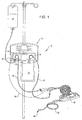
- Fig. 1 illustrates an exemplary embodiment of an interventional catheter assembly 10 comprising console unit 12, controller 30, and catheter system 32 having a rotatable operating head 40 located at or in proximity to the distal end of the catheter system and incorporating one or more cutter assemblies.
- Controller 30 may be used to manipulate (e.g. advance and/or rotate) the catheter system 32 and operating head 40, or alternative controls may be provided.
- the configuration of the operating head and cutter assemblies will be described below with reference to Figs. 2-7 .
- Console unit 12 may incorporate an infusion pump 14 and/or an aspiration pump 16.
- an infusate conduit 18 draws fluid from an infusate reservoir 20 and operably contacts the infusion pump 14 to provide fluid through an infusion lumen in catheter system 32 to one or more infusion ports provided in proximity to the operating head.
- fluids with entrained particulates may be withdrawn from the site of intervention through an aspiration lumen in catheter system 32 and conveyed to aspiration conduit 22, which is in operable contact with the aspiration pump 16, and communicates with the aspirate collection vessel 24.
- Console unit 12 may also provide a power source for operating the operating head and system components, or it may be in communication with an external power source. In the illustrated embodiment, console unit 12 provides power to the interventional catheter assembly and controller 30 by means of a device power port 25 and power cord 26.
- console unit for controlling operation of the interventional catheter as described herein.
- Software may be provided in a machine-readable medium storing executable code and/or other data to provide one or a combination of mechanisms to process user-specific data.
- various systems and components may be controlled using hardware or firmware implementations.
- Data storage and processing systems may also be provided in console unit 12.
- console unit 12 provides feedback of system and/or environmental conditions or operating parameters.
- the console unit may output operational information concerning operating conditions and feedback from the material removal site to the operator.
- console unit 12 provides continuously updated output to an operator of operating parameters such as operating head rotation rate, which may include the actual run speed as well as the desired speed; operating head advance rate; aspiration rate and/or volume; infusion rate and/or volume; elapsed run-time; and the like.
- Certain automated and selectable control features may be implemented in console unit 12. Preset routines or programs involving various operating parameters may be preselected, stored and selectable by an operator, for example.
- the disclosed material removal system implements control features based on an operator's input of specified parameters.
- Specified parameters may include, for example: lesion length, lesion type and character, such as calcified, fibrotic, lipid/fatty and the like; historical factors, such as restenosis; rate of blood flow; volume of blood flow; percentage of restriction; lumen type and/or location; lumen diameter; desired rotation rate and/or rotation profile for the cutter assembly; desired advance rate and/or advance profile for the cutter assembly; desired aspiration rate and/or profile; desired infusion rate and/or profile; and the like.
- control unit may calculate and implement automated operating conditions, such as: cutter assembly rotation rate and profile; cutter assembly advance rate and profile; aspiration rate and profile; infusion rate and profile; cutter assembly size; and the like.
- automated operating conditions such as: cutter assembly rotation rate and profile; cutter assembly advance rate and profile; aspiration rate and profile; infusion rate and profile; cutter assembly size; and the like.
- Various system operating parameters, operating conditions, patient conditions, and the like may also be recorded and stored during interventions to preserve a record of the patient and intervention operational parameters.
- fluid and associated particulates are aspirated from the intervention site at rates of at least 15 ml/min of operating head run time and in many embodiments, fluid and associated particulates are aspirated at rates of at least 25 ml/min of operating head run-time.
- the aspiration site may be more than a meter away from the controller 30 through an aspirate removal passageway located within the catheter system 32 and having a diameter of less than 2.54 mm (0.10 inch) for example between about 1.27 to 1.78 mm (0.050 to 0.070 inch).
- the distance that the aspirate travels between controller 30 and console unit 12 may be from about 0.5 meter to several meters, through an aspirate conduit that is between about 3.175 mm (0.125 inch) to about 25.4 mm (1.0 inch) in diameter.
- the blood and debris being aspirated are relatively viscous fluids, and achieving a relatively constant and high level of aspiration under these conditions is essential.
- aspiration pump 16 comprises a multi-lobed roller pump.
- the rotation rates of multiple rollers, or of a multi-lobed rotating structure, may be variable or selectable to control the aspiration rate and volume.
- Roller pumps permit fluid to flow in a conduit through the rollers of the pump at atmospheric pressure, and thus reduce or prevent the formation of bubbles and foam in the liquid being evacuated. Because the aspirate is at atmospheric pressure when it exits the roller pump, a simplified, atmospheric pressure collection vessel may be used rather than an evacuated collection vessel.
- a simple bag or another collection vessel, such as those used for collection of blood, may be used.
- a collection bag 24 and a sealed aspiration conduit may be provided as part of a sterile disposable interventional catheter kit.
- a distal end of the aspiration conduit may be pre-mounted on and sealed to the controller 30.
- a proximal portion of the aspiration conduit is mounted on the aspiration pump prior to operation of the interventional catheter and the aspirate collection bag is mounted to or in proximity to the control module.
- Infusion pump 14 may also comprise a multi-lobed roller pump employing variable or selectable rotation rates to control the infusion rate and volume.
- a simple bag or another infusate reservoir such as those used for intravenous infusions, may be used to supply the infusate.
- an infusate reservoir 20 having a sealed conduit that is mounted in the infusion pump 16 during operation of the interventional catheter may be provided.
- the sealed infusate conduit may be provided as part of the sterile disposable interventional catheter system and a distal end of the infusate conduit may be pre-mounted on and sealed to the controller 30.
- a proximal portion of the infusate conduit may be connected to an infusate reservoir, such as a saline bag, and mounted in proximity to the infusion pump prior to operation.
- a bubble detector 15 may be provided in association with console unit 12 and infusate conduit 18 to detect the presence of gas bubbles in the infusate.
- a control feature that automatically disables the infusion pump and/or power to the operating head may be activated upon detection of a fault (e.g. a bubble) in the infusate conduit.
- Console unit 12 may also have control switches for activating and shutting down the aspiration pump and system, and for activating and shutting down the infusion pump and system. These control features may be provided as simple on/off switches. Alternatively, systems providing different levels or rates of aspiration and/or infusion that are selectable by an operator may be provided. In addition, console unit 12 may be provided with a timing mechanism that determines, and displays, the elapsed time of operation of the operating head and/or the aspiration and infusion systems. The volumes of aspirate withdrawn and the volume of infusate introduced may also be detected and displayed by console unit 12.
- Detection systems for monitoring the levels of aspirate and infusate in the respective reservoirs may be incorporated and alarms indicating an overfill condition for the aspirate collection system or a low supply condition for the infusate reservoir may be provided.
- Back-up aspirate collection and infusate supply systems may also be provided.
- console unit 12 together with aspiration pump 16 and infusion pump 14 and the associated control and display features, is provided as a separate, re-usable unit, that may be used as standard equipment in operating rooms, for example.
- console unit 12 is not contaminated by contact with blood or aspirate during operation, and the power and control systems are durable and long-lasting and may be reused for many interventions.
- Console unit 12 may be provided in a housing designed to sit on a platform during operation, or the housing may be designed for mounting on a portable structure, such as an i.v. pole or another structure.
- the interventional catheter system comprising the catheter system 32 with operating head 40, controller 30, aspirate conduit 22, aspirate collection vessel 24, and infusion conduit 18 may be provided as a sterile, single use system kit.
- aspiration and/or infusion conduits terminate at or within controller 30, where they communicate with aspiration and infusion lumens within the catheter system 32.
- a rotatable drive shaft for driving the operating head is provided in catheter system 32.
- a guidewire may also transit controller 30 and catheter system 32.
- controller 30 or an associated control mechanism provides user-operated mechanisms for rotating and/or translating the operating head.
- Controller 30 which is constructed from a durable, sterilizable material, such as hard plastic, may be provided in any convenient ergonomic design and constructed for placement in proximity to and/or in contact with the external body.
- the controller may include an integrated handle for operator convenience in holding and supporting the controller during operation.
- Catheter system 32, exiting controller 30, is axially translatable with respect to controller 30 as the operating head and catheter system are guided to a target material removal site. It will be appreciated that some of the control and operational features described herein with reference to controller 30 may be provided in console unit 12 and, likewise, some of the control and operational features described with reference to console unit 12 may be provided in controller 30.
- the operating head 40 of the interventional catheter disclosed herein may comprise any of a variety of rotational cutting devices or assemblies having one or more cutting surface(s) for cutting, fragmentizing, pulverizing, ablating, scraping, grinding or otherwise reducing the size of undesired material and/or separating undesired material from healthy tissue, such as the walls of a blood vessel, in proximity to the target removal site.
- non-rotational operating heads may also be used that incorporate alternative material removal modalities, such as laser or ultrasound ablation techniques, or other types of ablation techniques.
- Rotational operating heads having differential cutter assemblies may be provided, as described in the U.S. patent publications incorporated herein by reference. Operating heads comprising abrasive rotational surfaces may also be used. The operating head, or subcomponents thereof, such as the cutting surfaces, may be coated with a radio-opaque material such as gold, platinum, inks and the like, to render the operating head radioscopically visible and to assist a medical professional in guiding and positioning the cutter assembly relative to an occlusion.
- a radio-opaque material such as gold, platinum, inks and the like
- Exemplary materials for construction of the cutting surface(s) of cutter assemblies of the present invention include metals, metal alloys, ceramics and cermet materials such as, but not limited to, various types of stainless steels, such as series 300 and/or 400, vanadium steel, nickel-titanium, titanium, titanium-containing metals and oxide ceramics.
- Metallic materials such as stainless steels may be hardened using well-known techniques.
- cutter surfaces are constructed from hard materials and may be treated to impart even greater hardness to the cutter surfaces.
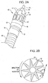
- Fig. 2A illustrates a fixed blade cutter assembly having a plurality of differential cutting surfaces according to the present invention.
- Cutter assembly 40 comprises a plurality of cutter blades 42 arranged in a radially symmetrical arrangement with respect to a central longitudinal axis of the cutter assembly. Each of the cutter blades 42 is joined at a distal end to form a distal bore 44 which serves as a rotating bearing for a guidewire 45.
- cutter blades 42 may alternatively terminate at their distal ends in a blunt or rounded or pointed structure without forming a distal bore.
- Cutter blades 42 terminate at their proximal ends in a proximal ring-like collar 46.
- cutter assembly 40 may be mounted to a drive shaft, a catheter system, or an intermediate bearing structure.
- Fig. 2 illustrates an embodiment in which cutter assembly 40 is mounted to a rotating element 52 of bearing 50.
- a non-rotating element 54 of the bearing is mounted to a distal portion of catheter 56 or another cylindrical structure provided at a distal portion of the interventional catheter.
- the rotating bearing element and cutter assembly are rotated during operation by the drive shaft, while the non-rotating element of the bearing structure and the distal portion of the catheter remain stationary during rotation of the operating head.
- the overall outer configuration of cutter assembly 40 is generally round from an axial view and oblong or frusto-conical from a profile view.
- the outer edges of cutter blades 42 taper along a curved line between smaller diameter distal bore 44 and larger diameter proximal collar 46, such that the diameter of the cutter assembly decreases toward its distal end. This configuration allows the smaller diameter distal end of the cutter assembly to penetrate an obstruction or partial obstruction while providing a progressively larger bore as the cutter assembly is advanced through the obstruction.
- Each of the cutter blades 42 has a differential cutter surface on a leading edge 43 that contacts material to be removed when cutter assembly 40 is rotated during a material removal operation.
- Differential cutter surfaces may be optimized for use in different types of cutting environments, for different types of materials being removed, and for different applications, by providing different cant angles. In general, the higher the cant angle the more aggressive the action of the cutter surface.
- a cutter surface having a cant angle of less than 90° has previously been shown to be gentle and benign when it contacts a resilient surface, such as the wall of a body lumen, yet it effectively cuts and abrades less resilient materials, such as plaque, calcified material and thrombus, to provide effective removal of disease material.
- Cutter assemblies disclosed herein are benign to healthy, elastic tissue while providing effective removal of less elastic, disease tissue.
- the leading edge cutter surfaces are preferably generally smooth, although they may be provided as abrasive surfaces, or surfaces coated with abrasive materials, in alternative embodiments.
- the use of diamond grit or other types of abrasives on the cutting surfaces may reduce the size of particles generated during rotation of cutter assemblies, thereby improving the efficiency of removal of the particles and reducing the risk of undesirable side effects.
- the use of diamond grit or other types of abrasives is particularly advantageous when removing hard materials, and/or small, targeted areas of unwanted material.
- the diamond grit or other type of abrasive employed on the cutting surfaces may have a particle size of about 400 microns or less.
- the abrasive materials have a particle size of about 100 microns or less, while in some embodiments, the abrasives have a particle size of about 40 microns or less, generally between about 20 and 40 microns in size.
- the cant angle ⁇ formed by the leading edges 43 of cutter blades 42 and a line tangent to a circle circumscribing the outer edges of the cutter surfaces are illustrated in Fig. 2B .
- Cant angles ⁇ formed by leading edges 43 of cutter surfaces 42 are preferably less than 90°.
- the cant angle of the cutter blades is less than 80° and, in some embodiments, is about 70°.
- Trailing angles ⁇ formed by trailing edges 45 of cutter surfaces 42 are preferably less than the corresponding cant angles and, in many embodiments, are less than 70°.
- a plurality of generally oval ports 48 may be provided between neighboring blades for communication with an internal space of the cutter assembly. Ports 48 may be provided between each pair of neighboring blades, as illustrated, or fewer ports may be provided. In one embodiment, as illustrated, ports 48 are preferably provided in a proximal portion of the cutter assembly in proximity to the proximal collar. Ports 48 may be used as aspiration or infusion ports and communicate with an appropriate aspiration or infusion lumen provided within catheter 56. Additional aspiration and/or infusion ports may be provided in locations proximal to the cutter assembly.
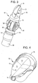
- Fig. 3 illustrates another cutter assembly for interventional catheters of the present invention in which a dual cutter assembly 60 comprises a fixed blade cutter 70 and an adjustable blade cutter assembly 80.
- cutter assembly 60 may be mounted to a drive shaft, a catheter system, or an intermediate bearing structure.
- Fig. 3 illustrates an embodiment in which cutter assembly 60 is mounted to a rotating element 92 of bearing 90.
- a non-rotating element 94 of the bearing is mounted to a distal portion of catheter 96 or another cylindrical structure provided at a distal portion of the interventional catheter.
- the rotating bearing element 92 and cutter assembly 60 are rotated during operation by the drive shaft, while the non-rotating element of the bearing structure 94 and the distal portion of the catheter 96 remain stationary during rotation of the operating head.
- Fixed blade cutter assembly 70 illustrated in isolation in Fig. 4 , comprises a plurality of differential cutting surfaces 72.
- the overall outer configuration of cutter assembly 70 is generally round from an axial view and oblong or frusto-conical from a profile view.
- the outer edges of cutter blades 72 taper along a curved line between smaller diameter distal bore 74 and larger diameter proximal collar 76, such that the diameter of the cutter assembly decreases toward its distal end. This configuration allows the smaller diameter distal end of the cutter assembly to penetrate an obstruction or partial obstruction while providing a progressively larger bore as the cutter assembly is advanced through the obstruction.
- Each of the cutter blades 72 is fixed on the cutter assembly and preferably has a differential cutter surface on a leading edge 73 that contacts material to be removed when cutter assembly 70 is rotated during a material removal operation.
- the leading edge cutter surfaces are preferably generally smooth, although they may be provided as abrasive surfaces, or surfaces coated with abrasive materials, in alternative embodiments.
- the blades may be provided as generally planar surfaces 75 at a distal portion, terminating proximally in a curved or scooped area 77.
- the cant angles formed as described above by the leading edges 73 of cutter surfaces 72 and a line tangent to a circle circumscribing the outer edges of the cutter surfaces at each cutter surface are preferably less than 90°.
- the cant angle of the cutter blades is less than 80° and, in some embodiments, is about 70°.
- the trailing angles ⁇ formed by the trailing edges 78 of cutter surfaces 72 and a line tangent to a circle circumscribing the edges of the cutter surfaces are generally less than the cant angle ⁇ and, in many embodiments, are less than 70°.
- the fixed blade cutter assembly 70 does not have ports or openings, other than the guidewire bore 74, communicating with an interior of the assembly. Aspiration and/or infusion ports may be provided elsewhere in proximity to the cutter assembly, if desired.
- the number of cutter blades provided on fixed cutter assembly 70 of the present invention may vary depending on the interventional application and the nature of the material being removed. As few as three blades may be provided and as many as 5-7 blades may be provided in a radially symmetrical arrangement. Fixed blade cutter assemblies having 3 or more blades are preferred for many applications.
- Cutter assembly 60 illustrated in Fig. 3 also incorporates an adjustable blade cutter assembly 80 having a plurality of cutter surfaces 82 presenting a different cutting profile than that of cutter surfaces of the distal blades 72.
- adjustable blade cutter assemblies are known in the art and may be used in combination with a fixed blade distal cutter assembly of the present invention.
- Cutter assembly 80 may comprise a plurality of pivoting blades, for example, that move between a tangential, non-cutting, position and a radial, cutting, position by changing the direction of rotation of the cutter assembly.
- the fixed blade cutter assembly may be operated in one direction of rotation in a first cutting operation to clear a passageway, and the adjustable blade cutter may be operated in an opposite direction of rotation in a second cutting operation to clear a larger opening in a lumen or cavity.
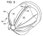
- cutter assembly 100 has a plurality of cutter blades 102 oriented for operation by rotation in a counterclockwise direction B.
- Cutter blades 102 incorporate upstanding cutter surfaces 106 adjacent shoulders 104.
- the embodiment illustrated in Fig. 5 does not incorporate a chamfered edge, but the shoulders 104 provide generally atraumatic contact with tissue.
- the trailing edges of cutter blades 102 may be provided at a shallow angle to cutter surfaces 106, providing a relatively blunt circumferential edge on cutter blades 102.
- Fig. 6 illustrates the distal end of one embodiment of an interventional catheter of the present invention.
- the operating head comprises a multi-bladed cutter assembly 150 having a plurality of raised blades 152 arranged in a radially symmetrical configuration.
- Blades 152 are preferably differential cutting blades, and cutting assembly 150 may incorporate a plurality of ports 154 arranged in a radially symmetrical configuration in the spaces between blades 152.
- Ports 154 are shown provided between each set of neighboring blade structures in Fig. 6 , but it will be appreciated that fewer ports may be provided.
- Ports 154 are preferably provided in a generally proximal portion of cutter assembly 150 and may have a generally oblong configuration, as illustrated, or may take a variety of other configurations.
- the distal end of the interventional catheter illustrated in Fig. 6 additionally comprises a large port 156 located in a distal portion of the catheter, or a proximal portion of the cutter assembly, proximal to blades 152.
- Port 156 is generally provided as a window or cut-out in a cylindrical structure and preferably spans at least 10% of the circumference of the structure; more preferably at least 20% of the circumference of the structure; and yet more preferably at least 30% of the circumference of the structure.
- the cylindrical structure supporting port 156 may be a distal catheter portion, or port 156 may be provided in a generally cylindrical tubular shell structure mounted, directly or indirectly, to a distal catheter portion 160. In one embodiment, illustrated in Fig.
- a rigid cylindrical shell 158 is mounted to distal catheter portion 160 at its proximal end and is mounted to, or forms a stationary element of, bearing 162 at its distal end.
- Bearing 162 allows distal catheter portion 160 and cylindrical shell 158 to remain stationary during rotation of cutting assembly 150.
- Bearing 162 may also provide limited articulation of cutting assembly 150 about its longitudinal axis.
- Ports 154 may be operated as aspiration or infusion ports and, likewise, enlarged proximal port 156 may be operated as an aspiration or infusion port.
- proximal port 156 is provided as an aspiration port and communicates with an aspiration lumen within catheter 160 that communicates with aspiration conduit 22, while ports 154 operate as infusion ports and communicate with an infusion lumen within catheter 160 that communicates with infusion conduit 26.
- port 156 is provided as an infusion port and communicates with an infusion lumen within catheter 160 that communicates with infusion conduit 26, while ports 154 operate as aspiration ports and communicate with an aspiration lumen within catheter 160 that communicates with aspiration infusion conduit 22.
- ports 154 may be operated as aspiration or infusion ports and enlarged proximal port 156 operates as an aspiration port and incorporates a rotating macerator assembly 164, which is described in greater detail below.
- operating head 170 comprises a distal cutter assembly 172 mounted to a bearing system 176 that allows rotation of the operating head while the catheter components proximal to the operating head remain stationary during rotation.
- the interventional catheter illustrated in Fig. 7 additionally comprises a proximal aspiration port 178 provided as an opening in a cylindrical shell structure 180 located proximal to the cutter assembly 172.
- Aspiration port 178 communicates with an aspiration lumen within catheter 182 that communicates proximally with aspiration conduit 22.
- Proximal aspiration port 178 may be provided as an opening or window in a distal catheter portion, or it may be provided as an opening in a substantially rigid cylindrical shell 180, as illustrated.
- Cylindrical shell 180 is constructed from a generally rigid, durable material, such as surgical steel or stainless steel, and has a length that is approximately the same as that of the cutter assembly.
- Shell 180 is generally mounted to, or forms a stationary component of, bearing 176 at its distal end. Bearing 176 allows catheter 182 and cylindrical casing 180 to remain stationary during rotation of operating head 150. Bearing 176 may also provide limited articulation of operating head 170 about its longitudinal axis.
- Aspiration port 178 may be provided as a window spanning at least 15% of the circumference of the shell structure; more preferably at least 25% of the circumference of the shell structure; and yet more preferably at least 35% of the circumference of the shell structure.
- the proximal aspiration port may be provided, for example, in a generally ovoid, rectangular, or square profile.
- the surface area, or size of the opening of port 178 depends on the relative sizes of the operating head, the catheter and the size of debris that is anticipated will be generated during operation of the operating head.
- port 178 has a length in the direction of the longitudinal axis of the interventional catheter that is from about 0.5 to about 2.5 times the transverse width of the port as measured on the arc of the cylindrical surface, preferably from about 0.7 to about 2.0 times the transverse width of the port.
- aspiration port 178 has an opening, or surface area that is between about 0.5 to about 20 mm 2 , preferably between about 0.5 and 10 mm 2 in surface area.
- the interventional catheter of Fig. 7 incorporates a macerator assembly 190 mounted for rotation inside cylindrical shell 180.
- Macerator assembly 190 rotates within the inner cavity of cylindrical shell 180 and has projecting bars, described in detail below, that interact with walls of the aspiration port 178 and the inner surface of cylindrical shell 180 to grind or macerate debris that is aspirated through port 178.
- the interventional catheter illustrated in Fig. 7 additionally incorporates a plurality of infusion ports 185 located proximally with respect to aspiration port 178, but in proximity to the aspiration port and operating head 170.
- Infusion ports 185 which may be provided in an outer sheath 184, as shown in Fig. 7 , communicate with an infusion lumen in the catheter assembly, which communicates with infusion conduit 26. In certain embodiments, between two and twenty, for example twelve, infusion ports 185 are provided in an infusion sheath 184 mounted to distal catheter 182.
- the infusion ports may have a generally uniform size, or infusion ports of different sizes may be provided.
- the infusion ports may be generally cylindrical, as shown in Fig. 7 , or they may have alternative configurations.
- Each infusion port 185 may have a diameter of approximately 0.005 in. to 0.20 in., more preferably from about 0.006 in. to about 0.015 in. Infusion ports having diameters of about 0.010 in. are especially preferred for certain applications.. In one embodiment, the infusion ports are spaced in a generally circumferential pattern to provide a substantially uniform flow of infusate around the circumference of the infusion sheath.
- a single infusion port having a surface area generally equal to or less than the surface area of the aspiration port may be provided proximally to the aspiration port.
- a plurality of infusion ports may also be spaced relatively closely and arranged to provide targeted infusion, resulting in a higher volume or pressure of infusate at different locations around the circumference of the infusion sheath. Providing a large infusion port, or a series of infusion ports in close proximity to one another allows directional flow of infusate and may facilitate aspiration of debris and/or positioning of the operating head.
- the infusion rate and pressure is relatively low, unlike many prior art systems in which a high rate of fluid infusion is employed to break-up unwanted material or to guide an operating head.
- the pressure of the infusion fluid as measured at the infusion pump may from about 5.5-13.8 bar (80 to 200 psi).
- the volume ratio of infusate to aspirate is also important in many applications.
- the rate of infusion is generally greater than the rate of aspiration.
- the volume ratio of infusate to aspirate may be greater than about 1:1 and less than about 3:1.
- the volume ratio of infusate to aspirate may be greater than about 1.5:1 and less than about 2.5:1.
- the volume ratio of infusate to aspirate is approximately 1.5:1, 2:1 or 2.5:1.
- the rate of infusion is approximately 45-100 ml/min of device run-time, and the rate of aspiration is approximately 20-60 ml/min of device run-time.
- the rate of infusion is approximately 45-150 ml/min, for example 50-90 ml/min, of device run-time, and the rate of aspiration is approximately 20-90 ml/min, for example, 20-60 ml/min of device run-time.
- a bubble detection device is provided in proximity to an infusate conduit and operates to detect gas bubbles in the infusate fluid.
- An alarm may be triggered upon detection of a bubble, or a control mechanism may inactivate the infusion and aspiration systems in response to detection of a bubble.
- Power to the operating head may also be inactivated upon detection of a bubble to inactivate the system and prevent introduction of the bubble into the patient.
- Activation and inactivation of the infusion and aspiration systems may be controlled by an operator using operator selectable features and controls. Alternatively, various operating protocols may be programmed into the system or provided as selectable features. Operation of the aspiration and infusion systems may be coordinated in a variety of ways, for example, with operation of the operating head. Activation and inactivation of the operating head is generally controlled by the operator. In one embodiment, the infusion system is primed to ensure that the infusate conduit is filled with liquid and a reliable supply of infusate to infusion ports in proximity to the operating head is established prior to guidance of the interventional catheter to the site of intervention. In one embodiment, the infusate and aspiration systems are activated automatically upon activation of the operating head.
- the infusate and aspiration systems are activated after a generally short delay period following activation of the operating head.
- the infusion and aspiration systems may also be inactivated automatically upon inactivation of the operating head.
- the infusion and/or aspiration systems may be inactivated after a predetermined or selectable time period following inactivation of the operating head.
- the system may optionally incorporate override controls that allow an operator to override a programmed infusion or aspiration feature.
Landscapes
- Health & Medical Sciences (AREA)
- Life Sciences & Earth Sciences (AREA)
- Heart & Thoracic Surgery (AREA)
- Veterinary Medicine (AREA)
- Engineering & Computer Science (AREA)
- Biomedical Technology (AREA)
- Animal Behavior & Ethology (AREA)
- General Health & Medical Sciences (AREA)
- Public Health (AREA)
- Surgery (AREA)
- Vascular Medicine (AREA)
- Anesthesiology (AREA)
- Hematology (AREA)
- Nuclear Medicine, Radiotherapy & Molecular Imaging (AREA)
- Medical Informatics (AREA)
- Molecular Biology (AREA)
- Biophysics (AREA)
- Physics & Mathematics (AREA)
- Pathology (AREA)
- Radiology & Medical Imaging (AREA)
- Pulmonology (AREA)
- Optics & Photonics (AREA)
- Orthopedic Medicine & Surgery (AREA)
- Surgical Instruments (AREA)
- Media Introduction/Drainage Providing Device (AREA)
Claims (15)
- Interventionskatheteranordnung, die aufweist:(a) einen Katheter (32) zur Einführung und Führung zu einer Zielstelle in einem Körper;(b) einen rotierenden Arbeitskopf (40, 60, 70, 100, 150, 160), der nahe einem distalen Ende des Katheters montiert ist, wobei der Arbeitskopf mehrere externe Schneidelemente (42, 72, 82, 93, 152, 172) zum Aufbrechen von Obstruktionsmaterial in Teilchen an der Zielstelle aufweist;(c) mindestens einen Aspirationsport (156, 178), der nahe den externen Schneidelementen und in Kommunikation mit einem ersten abgedichteten Lumen zum Abziehen von Fluiden und Obstruktionsmaterial von der Zielstelle liegt; und(d) mehrere Infusionsports (185), die auch nahe den externen Schneidelementen liegen und mit einem Infusionslumen im Katheter kommunizieren;dadurch gekennzeichnet, dass der mindestens eine Aspirationsport (156, 178) proximal zum Arbeitskopf (40, 60, 70, 100, 150, 160) und zu dessen externen Schneidelementen (42, 72, 82, 93, 152, 172) liegt und sich über mindestens 20 % eines Umfangs des Katheters erstreckt,
und dadurch, dass die mehreren Infusionsports (185) im Hinblick auf den mindestens einen Aspirationsport (156, 178) proximal liegen. - Interventionskatheteranordnung nach Anspruch 1, wobei sich der mindestens eine Aspirationsport (156, 178) über mindestens 30 % des Umfangs des Katheters erstreckt.
- Interventionskatheteranordnung nach Anspruch 1, wobei die mehreren Flüssigkeitsinfusionsports (185) um den Katheter über den Umfang beabstandet sind, um für im Wesentlichen gleichmäßige Verteilung von Infusionsfluid um den Umfang des Katheters zu sorgen.
- Interventionskatheteranordnung nach Anspruch 1, wobei die mehreren Flüssigkeitsinfusionsports (185) ungleichmäßig beabstandet sind, um Infusionsfluidfluss in mindestens einer gewünschten Richtung um den Umfang des Katheters zu leiten.
- Interventionskatheteranordnung nach Anspruch 1, die zusätzlich mindestens einen im Arbeitskopf und in Kommunikation mit einem abgedichteten Lumen liegenden Port (48, 154) zur Aspiration oder Infusion von Flüssigkeit aufweist.
- Interventionskatheteranordnung nach Anspruch 1, die zusätzlich aufweist:ein Infusionssystem zum Bereitstellen von Infusionsfluid und ein Aspirationssystem, wobei das Infusions- und Aspirationssystem im Betrieb der Interventionskatheteranordnung so gesteuert werden, dass sie für Volumenverhältnisse von Infusat zu Aspirat über etwa 1:1 und unter etwa 2,5:1 sorgen.
- Interventionskatheteranordnung nach Anspruch 1, die zusätzlich aufweist:ein Infusionssystem zum Bereitstellen von Infusionsfluid an einem Ort nahe der Zielstelle und ein Aspirationssystem, wobei das Infusions- und Aspirationssystem im Betrieb der Interventionskatheteranordnung so gesteuert werden, dass sie für eine Infusionsrate von etwa 45 bis 150 ml/min und eine Aspirationsrate von etwa 20 bis 90 ml/min sorgen.
- Interventionskatheteranordnung nach Anspruch 1, die zusätzlich aufweist:ein Infusionssystem zum Bereitstellen von Infusionsfluid an einem Ort nahe der Zielstelle und ein Aspirationssystem, wobei das Infusions- und Aspirationssystem nach einer ausgewählten Zeitdauer nach Deaktivierung des Arbeitskopfs automatisch deaktiviert werden.
- Interventionskatheteranordnung nach Anspruch 1, wobei die Schneidelemente feste Schneidklingen sind.
- Interventionskatheteranordnung nach Anspruch 1, wobei die Schneidelemente einstellbare Schneidklingen sind.
- Interventionskatheteranordnung nach Anspruch 1, wobei die Schneidelemente differenzielle Schneidklingen sind.
- Interventionskatheteranordnung nach Anspruch 1, wobei der Arbeitskopf zusätzlich eine Schleiffläche aufweist.
- Interventionskatheteranordnung nach Anspruch 1, die zusätzlich ein Infusionssystem aufweist, das Infusionsfluid distal zum Arbeitskopf bereitstellt.
- Interventionskatheteranordnung nach Anspruch 1, die zusätzlich ein Infusionssystem mit mindestens einem Flüssigkeitsinfusionsport aufweist, der für Richtungsfluss von Infusat sorgt.
- Interventionskatheteranordnung nach Anspruch 1, die zusätzlich ein Infusionssystem aufweist, das Infusionsfluid mit Drücken von etwa 5,52 x 10⁵ bis 13,79 x 10⁵ Pa (80 bis 200 psi) im Betrieb bereitstellt.
t
Applications Claiming Priority (3)
| Application Number | Priority Date | Filing Date | Title |
|---|---|---|---|
| US82820906P | 2006-10-04 | 2006-10-04 | |
| US89417307P | 2007-03-09 | 2007-03-09 | |
| EP07843776.1A EP2068730B1 (de) | 2006-10-04 | 2007-10-03 | Interventionskatheter |
Related Parent Applications (3)
| Application Number | Title | Priority Date | Filing Date |
|---|---|---|---|
| EP07843776.1A Division-Into EP2068730B1 (de) | 2006-10-04 | 2007-10-03 | Interventionskatheter |
| EP07843776.1A Division EP2068730B1 (de) | 2006-10-04 | 2007-10-03 | Interventionskatheter |
| EP07843776.1 Division | 2007-10-03 |
Publications (2)
| Publication Number | Publication Date |
|---|---|
| EP2462881A1 EP2462881A1 (de) | 2012-06-13 |
| EP2462881B1 true EP2462881B1 (de) | 2016-08-24 |
Family
ID=39269201
Family Applications (4)
| Application Number | Title | Priority Date | Filing Date |
|---|---|---|---|
| EP12152930.9A Active EP2462881B1 (de) | 2006-10-04 | 2007-10-03 | Interventionskatheter |
| EP07843776.1A Active EP2068730B1 (de) | 2006-10-04 | 2007-10-03 | Interventionskatheter |
| EP16177750.3A Active EP3103404B1 (de) | 2006-10-04 | 2007-10-03 | Interventionskatheter |
| EP12152932.5A Ceased EP2462882B1 (de) | 2006-10-04 | 2007-10-03 | Interventionskatheter |
Family Applications After (3)
| Application Number | Title | Priority Date | Filing Date |
|---|---|---|---|
| EP07843776.1A Active EP2068730B1 (de) | 2006-10-04 | 2007-10-03 | Interventionskatheter |
| EP16177750.3A Active EP3103404B1 (de) | 2006-10-04 | 2007-10-03 | Interventionskatheter |
| EP12152932.5A Ceased EP2462882B1 (de) | 2006-10-04 | 2007-10-03 | Interventionskatheter |
Country Status (8)
| Country | Link |
|---|---|
| US (9) | US8852219B2 (de) |
| EP (4) | EP2462881B1 (de) |
| JP (2) | JP4787363B2 (de) |
| KR (2) | KR101382094B1 (de) |
| CN (2) | CN101522115B (de) |
| AU (1) | AU2007303132B2 (de) |
| CA (1) | CA2663014C (de) |
| WO (1) | WO2008042987A2 (de) |
Families Citing this family (285)
| Publication number | Priority date | Publication date | Assignee | Title |
|---|---|---|---|---|
| US7708749B2 (en) | 2000-12-20 | 2010-05-04 | Fox Hollow Technologies, Inc. | Debulking catheters and methods |
| US6299622B1 (en) | 1999-08-19 | 2001-10-09 | Fox Hollow Technologies, Inc. | Atherectomy catheter with aligned imager |
| US8328829B2 (en) | 1999-08-19 | 2012-12-11 | Covidien Lp | High capacity debulking catheter with razor edge cutting window |
| US7713279B2 (en) | 2000-12-20 | 2010-05-11 | Fox Hollow Technologies, Inc. | Method and devices for cutting tissue |
| ATE499054T1 (de) | 2000-12-20 | 2011-03-15 | Fox Hollow Technologies Inc | Verkleinerungskatheter |
| EP1530441B1 (de) | 2002-06-13 | 2017-08-02 | Ancora Heart, Inc. | Vorrichtung und verfahren zur herzklappenreparatur |
| EP1613390A2 (de) | 2003-04-08 | 2006-01-11 | Medrad, Inc. | Fluid-abgabesysteme, vorrichtungen und verfahren zur abgabe von gefährlichen fluids |
| US8246640B2 (en) | 2003-04-22 | 2012-08-21 | Tyco Healthcare Group Lp | Methods and devices for cutting tissue at a vascular location |
| US7393181B2 (en) | 2004-09-17 | 2008-07-01 | The Penn State Research Foundation | Expandable impeller pump |
| GR20050100452A (el) | 2005-09-02 | 2007-04-25 | Estelle Enterprises Limited | Συστημα καθετηρα ανταλλαγης υγρων |
| AU2007230945B2 (en) | 2006-03-23 | 2013-05-02 | The Penn State Research Foundation | Heart assist device with expandable impeller pump |
| US20130218161A1 (en) * | 2011-08-25 | 2013-08-22 | The Cleveland Clinic Foundation | Method and apparatus for material removal |
| US20070276419A1 (en) | 2006-05-26 | 2007-11-29 | Fox Hollow Technologies, Inc. | Methods and devices for rotating an active element and an energy emitter on a catheter |
| WO2008005888A2 (en) | 2006-06-30 | 2008-01-10 | Atheromed, Inc. | Atherectomy devices and methods |
| US20080004645A1 (en) | 2006-06-30 | 2008-01-03 | Atheromed, Inc. | Atherectomy devices and methods |
| US8361094B2 (en) | 2006-06-30 | 2013-01-29 | Atheromed, Inc. | Atherectomy devices and methods |
| US8007506B2 (en) | 2006-06-30 | 2011-08-30 | Atheromed, Inc. | Atherectomy devices and methods |
| US20090018566A1 (en) | 2006-06-30 | 2009-01-15 | Artheromed, Inc. | Atherectomy devices, systems, and methods |
| US9492192B2 (en) * | 2006-06-30 | 2016-11-15 | Atheromed, Inc. | Atherectomy devices, systems, and methods |
| US20080045986A1 (en) | 2006-06-30 | 2008-02-21 | Atheromed, Inc. | Atherectomy devices and methods |
| US8394078B2 (en) * | 2006-10-04 | 2013-03-12 | Medrad, Inc. | Interventional catheters incorporating an active aspiration system |
| EP2462881B1 (de) * | 2006-10-04 | 2016-08-24 | Boston Scientific Limited | Interventionskatheter |
| US8388680B2 (en) | 2006-10-18 | 2013-03-05 | Guided Delivery Systems, Inc. | Methods and devices for catheter advancement and delivery of substances therethrough |
| US9028520B2 (en) | 2006-12-22 | 2015-05-12 | The Spectranetics Corporation | Tissue separating systems and methods |
| US8961551B2 (en) | 2006-12-22 | 2015-02-24 | The Spectranetics Corporation | Retractable separating systems and methods |
| EP2120737B1 (de) | 2007-02-05 | 2020-04-01 | Boston Scientific Limited | Thrombektomie-vorrichtung |
| US8070762B2 (en) | 2007-10-22 | 2011-12-06 | Atheromed Inc. | Atherectomy devices and methods |
| WO2009065078A1 (en) * | 2007-11-14 | 2009-05-22 | Pathway Medical Technologies, Inc. | Delivery and administration of compositions using interventional catheters |
| US10517617B2 (en) | 2007-12-20 | 2019-12-31 | Angiodynamics, Inc. | Systems and methods for removing undesirable material within a circulatory system utilizing a balloon catheter |
| US20110213392A1 (en) * | 2007-12-20 | 2011-09-01 | Vortex Medical | Systems and Methods for Removing Undesirable Material Within a Circulatory System |
| US8506512B2 (en) * | 2007-12-20 | 2013-08-13 | Angio Dynamics | Systems and methods for removing undesirable material within a circulatory system utilizing a balloon catheter |
| US8613717B2 (en) | 2007-12-20 | 2013-12-24 | Angiodynamics, Inc. | Systems and methods for removing and fragmenting undesirable material within a circulatory system |
| US8734374B2 (en) * | 2007-12-20 | 2014-05-27 | Angiodynamics, Inc. | Systems and methods for removing undesirable material within a circulatory system during a surgical procedure |
| US20170136158A1 (en) | 2015-10-16 | 2017-05-18 | Angiodynamics, Inc. | Systems and Methods for Removing Undesirable Material Within a Circulatory System |
| US11589880B2 (en) | 2007-12-20 | 2023-02-28 | Angiodynamics, Inc. | System and methods for removing undesirable material within a circulatory system utilizing during a surgical procedure |
| US20110213290A1 (en) * | 2007-12-20 | 2011-09-01 | Vortex Medical | Systems and Methods for Removing Undesirable Material Within a Circulatory System |
| US8784440B2 (en) | 2008-02-25 | 2014-07-22 | Covidien Lp | Methods and devices for cutting tissue |
| US9125562B2 (en) | 2009-07-01 | 2015-09-08 | Avinger, Inc. | Catheter-based off-axis optical coherence tomography imaging system |
| US8062316B2 (en) | 2008-04-23 | 2011-11-22 | Avinger, Inc. | Catheter system and method for boring through blocked vascular passages |
| US20100125253A1 (en) * | 2008-11-17 | 2010-05-20 | Avinger | Dual-tip Catheter System for Boring through Blocked Vascular Passages |
| US8096985B2 (en) | 2008-05-07 | 2012-01-17 | Guided Delivery Systems Inc. | Deflectable guide |
| JP5555242B2 (ja) | 2008-10-13 | 2014-07-23 | コヴィディエン リミテッド パートナーシップ | カテーテルシャフトを操作するデバイスおよび方法 |
| US9510854B2 (en) | 2008-10-13 | 2016-12-06 | Boston Scientific Scimed, Inc. | Thrombectomy catheter with control box having pressure/vacuum valve for synchronous aspiration and fluid irrigation |
| WO2010085456A1 (en) | 2009-01-20 | 2010-07-29 | Guided Delivery Systems Inc. | Anchor deployment devices and related methods |
| WO2010093630A2 (en) | 2009-02-10 | 2010-08-19 | Vesatek, Llc | Method and apparatus for manipulating a surgical guidewire |
| WO2010129075A1 (en) | 2009-04-28 | 2010-11-11 | Avinger, Inc. | Guidewire support catheter |
| AU2010241801B2 (en) | 2009-04-29 | 2013-04-11 | Covidien Lp | Methods and devices for cutting and abrading tissue |
| US8632557B2 (en) * | 2009-05-12 | 2014-01-21 | Cardiovascular Systems, Inc. | Rotational atherectomy device and method to improve abrading efficiency |
| BRPI1010595A2 (pt) * | 2009-05-14 | 2017-05-16 | Tyco Healthcare | cateteres de aterectomia facilmente limpaveis e metodos para uso |
| WO2010138927A2 (en) | 2009-05-28 | 2010-12-02 | Avinger, Inc. | Optical coherence tomography for biological imaging |
| WO2011003006A2 (en) | 2009-07-01 | 2011-01-06 | Avinger, Inc. | Atherectomy catheter with laterally-displaceable tip |
| WO2011008758A2 (en) * | 2009-07-16 | 2011-01-20 | Mayo Foundation For Medical Education And Research | Colonic lavage catheter |
| US9072540B2 (en) | 2009-08-12 | 2015-07-07 | Boston Scientific Limited | Adaptive tubing cassettes for use in connection with interventional catheter assemblies |
| US8388582B2 (en) | 2009-08-12 | 2013-03-05 | Medrad, Inc. | Systems and methods for operating interventional catheters using a common operating console and adaptive interface components |
| US8435228B2 (en) | 2009-08-12 | 2013-05-07 | Medrad, Inc. | Interventional catheter assemblies incorporating guide wire brake and management systems |
| US9005203B2 (en) | 2009-09-24 | 2015-04-14 | Imds, Llc | Reciprocating surgical instruments |
| US8617164B2 (en) * | 2009-09-24 | 2013-12-31 | Imds Corporation | Surgical rasping systems and methods |
| US9198675B2 (en) | 2009-09-24 | 2015-12-01 | Imds Llc | Reciprocating surgical instrument |
| US9033986B2 (en) | 2009-09-24 | 2015-05-19 | Imds, Llc | Reciprocating surgical instrument |
| WO2011068932A1 (en) | 2009-12-02 | 2011-06-09 | Fox Hollow Technologies, Inc. | Methods and devices for cutting tissue |
| EP2509498B1 (de) | 2009-12-08 | 2020-09-16 | Avinger, Inc. | Vorrichtungen zur prognose und vermeidung von restenosen |
| RU2520801C2 (ru) | 2009-12-11 | 2014-06-27 | ТАЙКО ХЕЛСКЕА ГРУП эЛПи | Устройство для съема материала с улучшенной эффективностью захвата и способы применения |
| US9050126B2 (en) | 2010-02-26 | 2015-06-09 | Cardiovascular Systems, Inc. | Rotational atherectomy device with electric motor |
| US8858546B2 (en) | 2010-05-12 | 2014-10-14 | Ethicon Endo-Surgery, Inc. | Instrument for debriding fistula and applying therapeutic cells |
| US8986331B2 (en) | 2010-05-12 | 2015-03-24 | Ethicon Endo-Surgery, Inc. | Instrument for debriding fistula and applying therapeutic cells |
| US9023070B2 (en) | 2010-05-13 | 2015-05-05 | Rex Medical, L.P. | Rotational thrombectomy wire coupler |
| US8764779B2 (en) | 2010-05-13 | 2014-07-01 | Rex Medical, L.P. | Rotational thrombectomy wire |
| US8663259B2 (en) | 2010-05-13 | 2014-03-04 | Rex Medical L.P. | Rotational thrombectomy wire |
| US9795406B2 (en) | 2010-05-13 | 2017-10-24 | Rex Medical, L.P. | Rotational thrombectomy wire |
| CA2799775C (en) | 2010-06-04 | 2020-03-24 | Medrad, Inc. | System and method for planning and monitoring multi-dose radiopharmaceutical usage on radiopharmaceutical injectors |
| CN102946815B (zh) | 2010-06-14 | 2015-07-15 | 科维蒂恩有限合伙公司 | 材料移除装置 |
| WO2014039096A1 (en) | 2012-09-06 | 2014-03-13 | Avinger, Inc. | Re-entry stylet for catheter |
| US11382653B2 (en) | 2010-07-01 | 2022-07-12 | Avinger, Inc. | Atherectomy catheter |
| EP2588012B1 (de) | 2010-07-01 | 2016-08-17 | Avinger, Inc. | Atherektomiekatheter mit länglich verschiebbaren antriebswellen |
| US9239049B2 (en) | 2010-07-16 | 2016-01-19 | Boston Scientific Limited | Peristaltic pump having a self-closing occlusion bed |
| RU2539720C2 (ru) | 2010-10-28 | 2015-01-27 | Ковидиен Лп | Устройство для удаления материала и способ применения |
| KR101518151B1 (ko) | 2010-11-11 | 2015-05-06 | 코비디엔 엘피 | 촬영용 가요성 디벌킹 카테터와, 사용 및 제조 방법 |
| CN103298420B (zh) * | 2010-11-15 | 2016-08-31 | 脊柱诊察公司 | 具有保持机构的组织去除系统 |
| JP5981442B2 (ja) | 2010-11-24 | 2016-08-31 | アシスト・メディカル・システムズ,インコーポレイテッド | 造影剤注入シリンジの入口弁システム |
| CN102058931B (zh) * | 2010-12-08 | 2012-11-07 | 上海交通大学医学院附属新华医院 | 一种柔索驱动的可吸附主动弯曲介入导管 |
| WO2012094641A2 (en) | 2011-01-06 | 2012-07-12 | Thoratec Corporation | Percutaneous heart pump |
| WO2012114333A1 (en) | 2011-02-24 | 2012-08-30 | Ilan Ben Oren | Hybrid catheter for vascular intervention |
| US9055964B2 (en) | 2011-03-15 | 2015-06-16 | Angio Dynamics, Inc. | Device and method for removing material from a hollow anatomical structure |
| US12245788B2 (en) | 2011-03-15 | 2025-03-11 | Angiodynamics, Inc. | Device and method for removing material from a hollow anatomical structure |
| EP2691038B1 (de) | 2011-03-28 | 2016-07-20 | Avinger, Inc. | Verstopfungsdurchquerungsvorrichtungen sowie bildgebungs- und atherektomievorrichtungen |
| US9949754B2 (en) | 2011-03-28 | 2018-04-24 | Avinger, Inc. | Occlusion-crossing devices |
| DE102011107613A1 (de) * | 2011-06-30 | 2013-01-03 | Siegfried Riek | Trokarsystem |
| US8992717B2 (en) | 2011-09-01 | 2015-03-31 | Covidien Lp | Catheter with helical drive shaft and methods of manufacture |
| USD685473S1 (en) | 2011-10-12 | 2013-07-02 | Grace Manufacturing, Inc. | Surgical reamer |
| US9345511B2 (en) | 2011-10-13 | 2016-05-24 | Atheromed, Inc. | Atherectomy apparatus, systems and methods |
| EP3653151A1 (de) | 2011-10-17 | 2020-05-20 | Avinger, Inc. | Atherektomiekatheter und kontaktloser antriebsmechanismus für katheter |
| USD685090S1 (en) | 2011-10-19 | 2013-06-25 | Grace Manufacturing, Inc. | Surgical reamer |
| US9345406B2 (en) | 2011-11-11 | 2016-05-24 | Avinger, Inc. | Occlusion-crossing devices, atherectomy devices, and imaging |
| US9216037B2 (en) | 2013-06-21 | 2015-12-22 | Previvo Genetics, Llc | Uterine lavage for embryo retrieval |
| US20150272622A1 (en) | 2011-12-22 | 2015-10-01 | Previvo Genetics, Llc | Recovery and processing of human embryos formed in vivo |
| US9282995B2 (en) | 2011-12-22 | 2016-03-15 | Previvo Genetics, Llc | Recovery and processing of human embryos formed in vivo |
| US9155555B2 (en) * | 2012-01-31 | 2015-10-13 | Medtronic Xomed, Inc. | Surgical instrument with distal bearing assembly |
| US20130253552A1 (en) * | 2012-03-20 | 2013-09-26 | Cardiovascular Systems, Inc. | Controller for an atherectomy device |
| US9186173B2 (en) * | 2012-04-27 | 2015-11-17 | Specialty Care, Inc. | Optical obturator system |
| US8721517B2 (en) | 2012-05-14 | 2014-05-13 | Thoratec Corporation | Impeller for catheter pump |
| US9872947B2 (en) | 2012-05-14 | 2018-01-23 | Tc1 Llc | Sheath system for catheter pump |
| WO2013172972A1 (en) | 2012-05-14 | 2013-11-21 | Avinger, Inc. | Optical coherence tomography with graded index fiber for biological imaging |
| US9446179B2 (en) | 2012-05-14 | 2016-09-20 | Thoratec Corporation | Distal bearing support |
| GB2504177B (en) | 2012-05-14 | 2014-12-10 | Thoratec Corp | Sheath system for catheter pump |
| WO2013172974A1 (en) | 2012-05-14 | 2013-11-21 | Avinger, Inc. | Atherectomy catheter drive assemblies |
| GB2504176A (en) | 2012-05-14 | 2014-01-22 | Thoratec Corp | Collapsible impeller for catheter pump |
| WO2013172970A1 (en) | 2012-05-14 | 2013-11-21 | Avinger, Inc. | Atherectomy catheters with imaging |
| CN102698328B (zh) * | 2012-06-08 | 2014-12-03 | 李广成 | 血肿清除器的双容器式平衡灌洗装置 |
| CN102698327A (zh) * | 2012-06-08 | 2012-10-03 | 李广成 | 血肿清除器 |
| US9050127B2 (en) * | 2012-06-27 | 2015-06-09 | Boston Scientific Limited | Consolidated atherectomy and thrombectomy catheter |
| US9358329B2 (en) | 2012-07-03 | 2016-06-07 | Thoratec Corporation | Catheter pump |
| EP4186557A1 (de) | 2012-07-03 | 2023-05-31 | Tc1 Llc | Motoranordnung für katheterpumpe |
| US9421311B2 (en) | 2012-07-03 | 2016-08-23 | Thoratec Corporation | Motor assembly for catheter pump |
| US10179009B2 (en) | 2012-08-07 | 2019-01-15 | Ahmad Abdul-Karim | Needleless transseptal access device and methods |
| US9498247B2 (en) | 2014-02-06 | 2016-11-22 | Avinger, Inc. | Atherectomy catheters and occlusion crossing devices |
| EP2892448B1 (de) | 2012-09-06 | 2020-07-15 | Avinger, Inc. | Ballonatherektomiekatheter mit bildgebung |
| US11284916B2 (en) | 2012-09-06 | 2022-03-29 | Avinger, Inc. | Atherectomy catheters and occlusion crossing devices |
| US9532844B2 (en) | 2012-09-13 | 2017-01-03 | Covidien Lp | Cleaning device for medical instrument and method of use |
| US20140081289A1 (en) | 2012-09-14 | 2014-03-20 | The Spectranetics Corporation | Lead removal sleeve |
| US9265925B2 (en) * | 2012-10-16 | 2016-02-23 | Acist Medical Systems, Inc. | Controlling flow in a medical injection system |
| US9943329B2 (en) | 2012-11-08 | 2018-04-17 | Covidien Lp | Tissue-removing catheter with rotatable cutter |
| EP2931148B1 (de) * | 2012-12-12 | 2016-09-21 | Covidien LP | Schneidvorrichtung für gewebeentfernungskatheter |
| US12514456B2 (en) | 2013-01-31 | 2026-01-06 | Eximo Medical Ltd. | System and methods for lesion characterization in blood vessels |
| US9108027B2 (en) | 2013-02-26 | 2015-08-18 | Boston Scientific Scimed, Inc. | Interventional catheter housing assemblies incorporating guide wire brakes and management systems |
| US11033728B2 (en) | 2013-03-13 | 2021-06-15 | Tc1 Llc | Fluid handling system |
| WO2014164136A1 (en) | 2013-03-13 | 2014-10-09 | Thoratec Corporation | Fluid handling system |
| US11077294B2 (en) | 2013-03-13 | 2021-08-03 | Tc1 Llc | Sheath assembly for catheter pump |
| US9456872B2 (en) | 2013-03-13 | 2016-10-04 | The Spectranetics Corporation | Laser ablation catheter |
| US9283040B2 (en) | 2013-03-13 | 2016-03-15 | The Spectranetics Corporation | Device and method of ablative cutting with helical tip |
| US10383691B2 (en) | 2013-03-13 | 2019-08-20 | The Spectranetics Corporation | Last catheter with helical internal lumen |
| US9291663B2 (en) | 2013-03-13 | 2016-03-22 | The Spectranetics Corporation | Alarm for lead insulation abnormality |
| US9883885B2 (en) | 2013-03-13 | 2018-02-06 | The Spectranetics Corporation | System and method of ablative cutting and pulsed vacuum aspiration |
| US10835279B2 (en) | 2013-03-14 | 2020-11-17 | Spectranetics Llc | Distal end supported tissue slitting apparatus |
| US9649437B2 (en) | 2013-03-14 | 2017-05-16 | Boston Scientific Scimed, Inc. | Interventional catheter assemblies and control components for interventional catheter assemblies |
| WO2014143064A1 (en) | 2013-03-15 | 2014-09-18 | Avinger, Inc. | Chronic total occlusion crossing devices with imaging |
| US11096717B2 (en) | 2013-03-15 | 2021-08-24 | Avinger, Inc. | Tissue collection device for catheter |
| US9925366B2 (en) | 2013-03-15 | 2018-03-27 | The Spectranetics Corporation | Surgical instrument for removing an implanted object |
| US10932670B2 (en) | 2013-03-15 | 2021-03-02 | Avinger, Inc. | Optical pressure sensor assembly |
| CA2901443A1 (en) * | 2013-03-15 | 2014-09-25 | Insera Therapeutics, Inc. | Vascular treatment devices and methods |
| US9668765B2 (en) | 2013-03-15 | 2017-06-06 | The Spectranetics Corporation | Retractable blade for lead removal device |
| US9308302B2 (en) | 2013-03-15 | 2016-04-12 | Thoratec Corporation | Catheter pump assembly including a stator |
| US10448999B2 (en) | 2013-03-15 | 2019-10-22 | The Spectranetics Corporation | Surgical instrument for removing an implanted object |
| US10842532B2 (en) | 2013-03-15 | 2020-11-24 | Spectranetics Llc | Medical device for removing an implanted object |
| EP2968742B1 (de) * | 2013-03-15 | 2020-12-02 | Tc1 Llc | Katheterpumpenanordnung mit einem stator |
| US9603618B2 (en) | 2013-03-15 | 2017-03-28 | The Spectranetics Corporation | Medical device for removing an implanted object |
| EP3341071B1 (de) | 2013-03-15 | 2020-01-29 | The Spectranetics Corporation | Medizinische vorrichtung zur entfernung eines implantierten objekts mittels lasergeschnittenen hypotubes |
| US20140378752A1 (en) * | 2013-06-21 | 2014-12-25 | Previvo Genetics, Llc | Uterine lavage for embryo retrieval |
| JP6517198B2 (ja) | 2013-07-08 | 2019-05-22 | アビンガー・インコーポレイテッドAvinger, Inc. | 介入療法を案内する弾性層の識別 |
| US20150018844A1 (en) * | 2013-07-11 | 2015-01-15 | Hsc Development Llc | Dissecting punch for follicular extraction and tools and methods using same |
| EP3027126B1 (de) * | 2013-07-31 | 2019-10-23 | Atheromed, Inc. | Atherektomievorrichtung |
| US10052122B2 (en) * | 2014-01-17 | 2018-08-21 | Cardiovascular Systems, Inc. | Spin-to-open atherectomy device with electric motor control |
| JP6539669B2 (ja) | 2014-02-06 | 2019-07-03 | アビンガー・インコーポレイテッドAvinger, Inc. | 粥腫切除カテーテル及び閉塞横断装置 |
| US12053203B2 (en) | 2014-03-03 | 2024-08-06 | Spectranetics, Llc | Multiple configuration surgical cutting device |
| EP3113701B1 (de) | 2014-03-03 | 2020-07-22 | The Spectranetics Corporation | Chirurgische schneidevorrichtung mit mehrfachkonfiguration |
| CN106456208B (zh) | 2014-03-12 | 2020-04-03 | 波士顿科学有限公司 | 注入润滑斑块切除导管 |
| US9248221B2 (en) | 2014-04-08 | 2016-02-02 | Incuvate, Llc | Aspiration monitoring system and method |
| US9433427B2 (en) | 2014-04-08 | 2016-09-06 | Incuvate, Llc | Systems and methods for management of thrombosis |
| JP5953445B2 (ja) * | 2014-04-11 | 2016-07-20 | オリンパス株式会社 | プラズマ処置システム |
| WO2015160979A1 (en) | 2014-04-15 | 2015-10-22 | Thoratec Corporation | Catheter pump with access ports |
| WO2015160943A1 (en) | 2014-04-15 | 2015-10-22 | Thoratec Corporation | Sensors for catheter pumps |
| US10583232B2 (en) | 2014-04-15 | 2020-03-10 | Tc1 Llc | Catheter pump with off-set motor position |
| EP4417244A3 (de) | 2014-04-15 | 2024-10-16 | Tc1 Llc | Katheterpumpeneinführersystem |
| US10363349B2 (en) | 2014-04-15 | 2019-07-30 | Tc1 Llp | Heart pump providing adjustable outflow |
| EP3145430B1 (de) | 2014-05-18 | 2019-07-03 | Eximo Medical Ltd. | System zur gewebeablation mit gepulstem laser |
| US9883877B2 (en) | 2014-05-19 | 2018-02-06 | Walk Vascular, Llc | Systems and methods for removal of blood and thrombotic material |
| US10405924B2 (en) | 2014-05-30 | 2019-09-10 | The Spectranetics Corporation | System and method of ablative cutting and vacuum aspiration through primary orifice and auxiliary side port |
| EP3160567A4 (de) * | 2014-06-26 | 2018-02-21 | Taryag Medical Ltd. | Fernbedienungssystem und verfahren zur verwendung bei intraluminalen oder intravaskulären operationen |
| WO2015200702A1 (en) | 2014-06-27 | 2015-12-30 | Covidien Lp | Cleaning device for catheter and catheter including the same |
| MX2017000303A (es) | 2014-07-08 | 2017-07-10 | Avinger Inc | Dispositivos para oclusion transversal cronica total de alta velocidad. |
| US10405878B2 (en) | 2014-07-25 | 2019-09-10 | Boston Scientific Scimed, Inc. | Rotatable medical device |
| WO2016028644A1 (en) | 2014-08-18 | 2016-02-25 | Thoratec Corporation | Guide features for percutaneous catheter pump |
| WO2016089847A1 (en) | 2014-12-04 | 2016-06-09 | Boston Scientific Scimed, Inc. | Rotatable medical device |
| WO2016118784A1 (en) | 2015-01-22 | 2016-07-28 | Thoratec Corporation | Attachment mechanisms for motor of catheter pump |
| WO2016118781A2 (en) | 2015-01-22 | 2016-07-28 | Thoratec Corporation | Motor assembly with heat exchanger for catheter pump |
| WO2016118777A1 (en) | 2015-01-22 | 2016-07-28 | Thoratec Corporation | Reduced rotational mass motor assembly for catheter pump |
| JP6746503B2 (ja) * | 2015-01-23 | 2020-08-26 | テルモ株式会社 | ガイドワイヤ |
| USD765243S1 (en) | 2015-02-20 | 2016-08-30 | The Spectranetics Corporation | Medical device handle |
| USD770616S1 (en) | 2015-02-20 | 2016-11-01 | The Spectranetics Corporation | Medical device handle |
| WO2016141358A1 (en) | 2015-03-05 | 2016-09-09 | Guided Delivery Systems Inc. | Devices and methods of visualizing and determining depth of penetration in cardiac tissue |
| US10314667B2 (en) | 2015-03-25 | 2019-06-11 | Covidien Lp | Cleaning device for cleaning medical instrument |
| US9907890B2 (en) | 2015-04-16 | 2018-03-06 | Tc1 Llc | Catheter pump with positioning brace |
| EP3322338B1 (de) | 2015-07-13 | 2025-02-12 | Avinger, Inc. | Mikrogeformte anamorphotische reflektorlinse für bildgeführte therapeutische/diagnosekatheter |
| US10292721B2 (en) | 2015-07-20 | 2019-05-21 | Covidien Lp | Tissue-removing catheter including movable distal tip |
| US10702292B2 (en) | 2015-08-28 | 2020-07-07 | Incuvate, Llc | Aspiration monitoring system and method |
| US10561440B2 (en) | 2015-09-03 | 2020-02-18 | Vesatek, Llc | Systems and methods for manipulating medical devices |
| US10314664B2 (en) | 2015-10-07 | 2019-06-11 | Covidien Lp | Tissue-removing catheter and tissue-removing element with depth stop |
| US20170100142A1 (en) | 2015-10-09 | 2017-04-13 | Incuvate, Llc | Systems and methods for management of thrombosis |
| US11147944B2 (en) | 2015-10-19 | 2021-10-19 | Actuated Medical, Inc. | Handset for occlusion clearing device |
| US9603656B1 (en) * | 2015-10-23 | 2017-03-28 | RELIGN Corporation | Arthroscopic devices and methods |
| BR112018011092A2 (pt) * | 2015-11-30 | 2018-11-21 | Piranha Medical Llc | remoção de bloqueio |
| US11141177B2 (en) | 2015-11-30 | 2021-10-12 | Piranha Medical Llc | Blockage clearing devices, systems, and methods |
| US10226263B2 (en) * | 2015-12-23 | 2019-03-12 | Incuvate, Llc | Aspiration monitoring system and method |
| CN108882857A (zh) | 2016-01-25 | 2018-11-23 | 阿维格公司 | 具有滞后修正的oct成像导管 |
| US10702298B2 (en) * | 2016-02-26 | 2020-07-07 | Cardiovascular Systems, Inc. | Powerline communication systems and methods for medical devices |
| US20190090843A1 (en) * | 2016-03-30 | 2019-03-28 | Koninklijke Philips N.V. | Flexible support member for intravascular imaging device and associated devices, systems, and methods |
| JP6959255B2 (ja) | 2016-04-01 | 2021-11-02 | アビンガー・インコーポレイテッドAvinger, Inc. | 粥腫切除用カテーテルデバイス |
| US10492805B2 (en) | 2016-04-06 | 2019-12-03 | Walk Vascular, Llc | Systems and methods for thrombolysis and delivery of an agent |
| US11684420B2 (en) | 2016-05-05 | 2023-06-27 | Eximo Medical Ltd. | Apparatus and methods for resecting and/or ablating an undesired tissue |
| US11344327B2 (en) | 2016-06-03 | 2022-05-31 | Avinger, Inc. | Catheter device with detachable distal end |
| US11224459B2 (en) | 2016-06-30 | 2022-01-18 | Avinger, Inc. | Atherectomy catheter with shapeable distal tip |
| EP3808401A1 (de) | 2016-07-21 | 2021-04-21 | Tc1 Llc | Gasgefüllte kammer für eine katheterpumpenmotoranordnung |
| EP3808403A1 (de) | 2016-07-21 | 2021-04-21 | Tc1 Llc | Fluiddichtungen für katheterpumpenmotoranordnung |
| US12138149B2 (en) * | 2016-09-07 | 2024-11-12 | Daniel Ezra Walzman | Endovascular devices and methods with filtering elements |
| JP6964082B2 (ja) | 2016-09-16 | 2021-11-10 | テルモ株式会社 | 医療デバイス |
| CN109715092B (zh) * | 2016-09-16 | 2021-07-09 | 泰尔茂株式会社 | 医疗器械 |
| US10028767B2 (en) | 2016-09-20 | 2018-07-24 | RELIGN Corporation | Arthroscopic devices and methods |
| AU2018239346B2 (en) * | 2017-03-20 | 2020-11-26 | Penumbra, Inc. | Methods and apparatus for removal of intracranial hemorrhage |
| US11690645B2 (en) | 2017-05-03 | 2023-07-04 | Medtronic Vascular, Inc. | Tissue-removing catheter |
| CN110582242B (zh) | 2017-05-03 | 2023-03-10 | 美敦力瓦斯科尔勒公司 | 组织移除导管 |
| US20180344993A1 (en) * | 2017-05-31 | 2018-12-06 | Robert A. Ganz | Blockage clearing devices, systems, and methods |
| EP4732889A2 (de) | 2017-06-07 | 2026-04-29 | Supira Medical, Inc. | Vorrichtungen, systeme und verfahren zur bewegung intravaskulärer flüssigkeiten |
| EP3658043A4 (de) * | 2017-07-27 | 2021-08-18 | Xablecath Inc. | Systeme und verfahren zur durchkreuzung und behandlung einer okklusion |
| EP4173579B1 (de) | 2017-08-02 | 2024-06-19 | Stryker Corporation | Chirurgische werkzeugsysteme |
| US11246649B2 (en) * | 2017-08-28 | 2022-02-15 | RELIGN Corporation | Arthroscopic devices and methods |
| US11511103B2 (en) | 2017-11-13 | 2022-11-29 | Shifamed Holdings, Llc | Intravascular fluid movement devices, systems, and methods of use |
| CN107981917B (zh) * | 2017-12-18 | 2024-06-14 | 高峰 | 一种用于微创人体静脉移植物获取的管式刀具 |
| CN108013918B (zh) * | 2017-12-26 | 2018-06-29 | 微创心脉医疗科技(上海)有限公司 | 一种取栓导管 |
| US11490923B2 (en) | 2018-01-05 | 2022-11-08 | Cook Medical Technologies Llc | Device with sharp and blunt regions for removing occlusions |
| FR3077209A1 (fr) * | 2018-02-01 | 2019-08-02 | Hemodia | Dispositifs et systemes de lavage / aspiration pulse jetable pour la chirurgie orthopedique |
| JP7410034B2 (ja) | 2018-02-01 | 2024-01-09 | シファメド・ホールディングス・エルエルシー | 血管内血液ポンプならびに使用および製造の方法 |
| WO2019152727A1 (en) | 2018-02-02 | 2019-08-08 | Kalera Medical, Inc. | Devices and methods for minimally invasive kidney stone removal by combined aspiration and irrigation |
| CN108324349B (zh) * | 2018-03-28 | 2023-07-28 | 宁波市第一医院 | 一种笔形清创器 |
| US12167867B2 (en) | 2018-04-19 | 2024-12-17 | Avinger, Inc. | Occlusion-crossing devices |
| EP3790478A1 (de) | 2018-05-08 | 2021-03-17 | Boston Scientific Scimed, Inc. | Zubehör zur führungsdrahtverwaltung einer vorrichtung |
| EP3801312B8 (de) * | 2018-06-04 | 2025-05-07 | Pavel V. Efremkin | Vorrichtungen für die intrakörperchirurgie |
| US10716880B2 (en) | 2018-06-15 | 2020-07-21 | Incuvate, Llc | Systems and methods for aspiration and monitoring |
| US11678905B2 (en) | 2018-07-19 | 2023-06-20 | Walk Vascular, Llc | Systems and methods for removal of blood and thrombotic material |
| WO2020028537A1 (en) | 2018-07-31 | 2020-02-06 | Shifamed Holdings, Llc | Intravascaular blood pumps and methods of use |
| WO2020073047A1 (en) | 2018-10-05 | 2020-04-09 | Shifamed Holdings, Llc | Intravascular blood pumps and methods of use |
| CN118697424A (zh) | 2018-11-16 | 2024-09-27 | 美敦力瓦斯科尔勒公司 | 组织去除导管 |
| CN110009962B (zh) * | 2019-04-16 | 2023-10-10 | 西南石油大学 | 基于运动缩放的血管介入手术训练系统 |
| WO2020226997A1 (en) * | 2019-05-03 | 2020-11-12 | Actuated Medical, Inc. | Handset for occlusion clearing device |
| US11819236B2 (en) | 2019-05-17 | 2023-11-21 | Medtronic Vascular, Inc. | Tissue-removing catheter |
| WO2020243571A1 (en) * | 2019-05-31 | 2020-12-03 | Microvention, Inc. | Clot retrieval |
| KR102518523B1 (ko) * | 2019-06-18 | 2023-04-06 | 고려대학교 산학협력단 | 경피적 석회 침작물 제거장치 |
| US11504181B2 (en) | 2019-07-01 | 2022-11-22 | RELIGN Corporation | Arthroscopic devices and methods |
| WO2021011473A1 (en) | 2019-07-12 | 2021-01-21 | Shifamed Holdings, Llc | Intravascular blood pumps and methods of manufacture and use |
| WO2021011659A1 (en) | 2019-07-15 | 2021-01-21 | Ancora Heart, Inc. | Devices and methods for tether cutting |
| US11654275B2 (en) | 2019-07-22 | 2023-05-23 | Shifamed Holdings, Llc | Intravascular blood pumps with struts and methods of use and manufacture |
| CN110313980B (zh) * | 2019-07-31 | 2023-04-18 | 宋勇 | 一种可变径输送套管和医疗器械套装 |
| EP4010046A4 (de) | 2019-08-07 | 2023-08-30 | Calomeni, Michael | Katheterblutpumpen und zusammenklappbare pumpengehäuse |
| US20220273335A1 (en) * | 2019-08-22 | 2022-09-01 | Philips Image Guided Therapy Corporation | Atherectomy devices including cutting blades having different edge shapes |
| EP4034192B1 (de) | 2019-09-25 | 2025-12-24 | Supira Medical, Inc. | Intravaskuläre blutpumpensysteme und verfahren zur verwendung und steuerung davon |
| WO2021062260A1 (en) | 2019-09-25 | 2021-04-01 | Shifamed Holdings, Llc | Catheter blood pumps and collapsible blood conduits |
| EP4034221B1 (de) | 2019-09-25 | 2024-11-13 | Shifamed Holdings, LLC | Katheterblutpumpen und zusammenklappbare pumpengehäuse |
| JP2022553223A (ja) | 2019-10-18 | 2022-12-22 | アビンガー・インコーポレイテッド | 閉塞横断装置 |
| EP4072650A4 (de) | 2019-12-11 | 2024-01-10 | Shifamed Holdings, LLC | Absteigende aorten- und hohlvenenblutpumpen |
| US12599758B2 (en) | 2019-12-19 | 2026-04-14 | Shifamed Holdings, Llc | Intravascular blood pumps, motors, and fluid control |
| WO2021123395A1 (en) * | 2019-12-20 | 2021-06-24 | Koninklijke Philips N.V. | Vibrational wire guide for coring and aspirating a venous obstruction |
| KR102354300B1 (ko) * | 2019-12-23 | 2022-01-21 | 주식회사 메디케어텍 | 막힘 현상이 방지되는 부비동 처치 시스템 |
| CA3160134A1 (en) | 2020-01-30 | 2021-08-05 | Acist Medical Systems, Inc. | Valve assembly |
| US11648020B2 (en) | 2020-02-07 | 2023-05-16 | Angiodynamics, Inc. | Device and method for manual aspiration and removal of an undesirable material |
| EP4114285A4 (de) | 2020-03-04 | 2024-03-06 | Shifamed Holdings, LLC | Thrombusentfernungssysteme und zugehörige verfahren |
| US11560964B2 (en) | 2020-08-21 | 2023-01-24 | Acist Medical Systems, Inc. | Valve actuation device coupling |
| US12376904B1 (en) | 2020-09-08 | 2025-08-05 | Angiodynamics, Inc. | Dynamic laser stabilization and calibration system |
| CN116685279A (zh) * | 2020-10-30 | 2023-09-01 | 波士顿科学国际有限公司 | 具有血流增强的斑块切除旋磨头 |
| CN112451045B (zh) * | 2020-12-16 | 2025-03-18 | 福建珞创医疗科技有限公司 | 一种血管钙化组织高效去除装置及其工作方法 |
| US11304723B1 (en) | 2020-12-17 | 2022-04-19 | Avantec Vascular Corporation | Atherectomy devices that are self-driving with controlled deflection |
| JP7690291B2 (ja) * | 2021-01-14 | 2025-06-10 | アズビル株式会社 | モジュールシステムおよびモジュール |
| US12274458B2 (en) | 2021-02-15 | 2025-04-15 | Walk Vascular, Llc | Systems and methods for removal of blood and thrombotic material |
| WO2022174175A1 (en) | 2021-02-15 | 2022-08-18 | Walk Vascular, Llc | Systems and methods for removal of blood and thrombotic material |
| WO2022187307A1 (en) * | 2021-03-03 | 2022-09-09 | Covidien Lp | Guidewires |
| US12582426B2 (en) | 2021-04-17 | 2026-03-24 | Inquis Medical, Inc. | Apparatuses for removing obstructive material from body lumens |
| US11376028B1 (en) | 2021-04-17 | 2022-07-05 | Inquis Medical, Inc. | Devices, systems, and methods for removing obstructive material from body lumens |
| US11679195B2 (en) | 2021-04-27 | 2023-06-20 | Contego Medical, Inc. | Thrombus aspiration system and methods for controlling blood loss |
| EP4340751A4 (de) | 2021-05-19 | 2025-03-26 | Shifamed Holdings, LLC | Thrombusentfernungssysteme und zugehörige verfahren |
| WO2022261043A1 (en) | 2021-06-07 | 2022-12-15 | Avantec Vascular Corporation | Hybrid atherectomy devices |
| JP2024524386A (ja) | 2021-06-28 | 2024-07-05 | インクイス メディカル,インコーポレーテッド | 閉塞性物質の除去を制御するための装置および方法 |
| CN116407226A (zh) * | 2021-12-31 | 2023-07-11 | 杭州唯强医疗科技有限公司 | 一种可调式旋切结构及可调式旋切抽吸装置 |
| EP4537867A3 (de) | 2022-03-02 | 2025-05-21 | Calyxo, Inc. | Nierensteinbehandlungssystem |
| US12220139B2 (en) | 2022-03-20 | 2025-02-11 | Von Vascular, Inc. | System, devices and methods for removing obstructions in body lumens |
| CN119698258A (zh) | 2022-04-22 | 2025-03-25 | 因奎斯医疗公司 | 用于移除凝块的抽取设备 |
| CN114617613B (zh) * | 2022-05-16 | 2022-08-16 | 广州博鑫医疗技术有限公司 | 一种冠状动脉旋磨介入系统 |
| WO2023220903A1 (zh) * | 2022-05-16 | 2023-11-23 | 广州博鑫医疗技术有限公司 | 一种冠状动脉旋磨介入系统 |
| US12038322B2 (en) | 2022-06-21 | 2024-07-16 | Eximo Medical Ltd. | Devices and methods for testing ablation systems |
| CN218651946U (zh) * | 2022-07-19 | 2023-03-21 | 武汉微新坦医疗科技有限公司 | 心肌调弯切割装置及系统 |
| US20240108412A1 (en) | 2022-09-29 | 2024-04-04 | Calyxo, Inc. | Tool guiding device for kidney stone treatment apparatus |
| WO2024145533A2 (en) | 2022-12-28 | 2024-07-04 | Inquis Medical, Inc. | Clot sensing methods and apparatuses |
| WO2025038507A1 (en) * | 2023-08-11 | 2025-02-20 | The Board Of Trustees Of The Leland Stanford Junior University | Devices, systems, and methods for performing thrombectomy procedures |
| WO2025038964A1 (en) | 2023-08-16 | 2025-02-20 | Avantec Vascular Corporation | Thrombectomy devices with lateral and vertical bias |
| US12544500B2 (en) | 2023-08-28 | 2026-02-10 | Incuvate, Llc | Systems and methods for injection and aspiration |
| US12280222B2 (en) | 2023-08-28 | 2025-04-22 | Incuvate, Llc | Systems and methods for injection and aspiration |
| US20250268620A1 (en) * | 2024-02-25 | 2025-08-28 | Center for Heart and Circulation PA | Atherectomy Catheter |
| WO2025194148A1 (en) * | 2024-03-14 | 2025-09-18 | The Board Of Trustees Of The Leland Stanford Junior University | Devices, systems, and methods for performing thrombectomy procedures |
| US12414785B1 (en) | 2025-03-17 | 2025-09-16 | Avantec Vascular Corporation | Cutters with pulsating vacuum control |
Family Cites Families (61)
| Publication number | Priority date | Publication date | Assignee | Title |
|---|---|---|---|---|
| US3922190A (en) | 1972-05-01 | 1975-11-25 | Inotech Process Ltd | Vacuum drainage device having a plurality of stepped blades |
| US4445509A (en) * | 1982-02-04 | 1984-05-01 | Auth David C | Method and apparatus for removal of enclosed abnormal deposits |
| JPS61500529A (ja) * | 1983-12-01 | 1986-03-27 | ハルコフスキイ ナウチノ−イススレドワテルスキイ インスチチユ−ト オブスチエイ イ ネオトロジノイ ヒルルギイ | 電気手術用器械 |
| US4790813A (en) | 1984-12-17 | 1988-12-13 | Intravascular Surgical Instruments, Inc. | Method and apparatus for surgically removing remote deposits |
| DE3541000C1 (de) | 1985-11-19 | 1987-05-07 | Karlsruhe Wiederaufarbeit | Stufenmesser fuer eine horizontale Brennelementbuendelschere |
| US4728319A (en) | 1986-03-20 | 1988-03-01 | Helmut Masch | Intravascular catheter |
| US5097849A (en) | 1989-08-17 | 1992-03-24 | Kensey Nash Corporation | Method of use of catheter with working head having selectable impacting surfaces |
| US5042984A (en) * | 1989-08-17 | 1991-08-27 | Kensey Nash Corporation | Catheter with working head having selectable impacting surfaces and method of using the same |
| WO1991002494A1 (en) * | 1989-08-18 | 1991-03-07 | Evi Corporation | Catheter atherotome |
| US5030201A (en) | 1989-11-24 | 1991-07-09 | Aubrey Palestrant | Expandable atherectomy catheter device |
| US5074841A (en) | 1990-01-30 | 1991-12-24 | Microcision, Inc. | Atherectomy device with helical cutter |
| US4981467A (en) * | 1990-02-27 | 1991-01-01 | Baxter International Inc. | Apparatus and method for the detection of air in fluid delivery systems |
| CA2048120A1 (en) | 1990-08-06 | 1992-02-07 | William J. Drasler | Thrombectomy method and device |
| US5078722A (en) | 1990-08-14 | 1992-01-07 | Cordis Corporation | Method and apparatus for removing deposits from a vessel |
| US5284486A (en) | 1991-06-11 | 1994-02-08 | Microvena Corporation | Self-centering mechanical medical device |
| US5569275A (en) * | 1991-06-11 | 1996-10-29 | Microvena Corporation | Mechanical thrombus maceration device |
| US5261877A (en) | 1991-07-22 | 1993-11-16 | Dow Corning Wright | Method of performing a thrombectomy procedure |
| EP0681458B1 (de) * | 1992-01-13 | 1998-06-03 | Schneider (Usa) Inc. | Schneideinrichtung für atherektomie-katheter |
| CA2107741C (en) | 1992-10-07 | 2000-06-27 | Peter T. Keith | Ablation devices and methods of use |
| US5417703A (en) * | 1993-07-13 | 1995-05-23 | Scimed Life Systems, Inc. | Thrombectomy devices and methods of using same |
| US5516242A (en) * | 1994-03-24 | 1996-05-14 | Andronica; Randall | Cutting tool and shank |
| AU701424B2 (en) | 1994-10-24 | 1999-01-28 | Smith & Nephew, Inc. | Hollow surgical cutter with apertured flutes |
| DE59609338D1 (de) | 1995-03-28 | 2002-07-18 | Straub Medical Ag Wangs | Katheter zum ablösen von abnormalen ablagerungen in menschlichen blutgefässen |
| US6905505B2 (en) | 1996-07-26 | 2005-06-14 | Kensey Nash Corporation | System and method of use for agent delivery and revascularizing of grafts and vessels |
| US6080170A (en) | 1996-07-26 | 2000-06-27 | Kensey Nash Corporation | System and method of use for revascularizing stenotic bypass grafts and other occluded blood vessels |
| US5779721A (en) | 1996-07-26 | 1998-07-14 | Kensey Nash Corporation | System and method of use for revascularizing stenotic bypass grafts and other blood vessels |
| US5947989A (en) * | 1996-12-12 | 1999-09-07 | United States Surgical Corporation | Method and apparatus for transmyocardial revascularization |
| US5913867A (en) | 1996-12-23 | 1999-06-22 | Smith & Nephew, Inc. | Surgical instrument |
| US6183487B1 (en) * | 1997-03-06 | 2001-02-06 | Scimed Life Systems, Inc. | Ablation device for reducing damage to vessels and/or in-vivo stents |
| US6063069A (en) | 1997-05-19 | 2000-05-16 | Micro Therapeutics Inc. | Method and apparatus for power lysis of a thrombus |
| US20060074442A1 (en) * | 2000-04-06 | 2006-04-06 | Revascular Therapeutics, Inc. | Guidewire for crossing occlusions or stenoses |
| US6053923A (en) * | 1998-03-17 | 2000-04-25 | Arthrotek, Inc. | Method and apparatus for abrading tissue |
| US6666874B2 (en) * | 1998-04-10 | 2003-12-23 | Endicor Medical, Inc. | Rotational atherectomy system with serrated cutting tip |
| US6001112A (en) * | 1998-04-10 | 1999-12-14 | Endicor Medical, Inc. | Rotational atherectomy device |
| JP4147673B2 (ja) | 1999-03-12 | 2008-09-10 | 日立工機株式会社 | セーバソー |
| AU3741400A (en) * | 1999-03-15 | 2000-10-04 | Prolifix Medical, Inc. | Shielded atherectomy device |
| US6238405B1 (en) | 1999-04-30 | 2001-05-29 | Edwards Lifesciences Corp. | Percutaneous material removal device and method |
| US6454775B1 (en) | 1999-12-06 | 2002-09-24 | Bacchus Vascular Inc. | Systems and methods for clot disruption and retrieval |
| US6702830B1 (en) | 1999-09-17 | 2004-03-09 | Bacchus Vascular, Inc. | Mechanical pump for removal of fragmented matter and methods of manufacture and use |
| US6550702B2 (en) | 2000-02-29 | 2003-04-22 | William R Champlin | Apparatus for removing and chipping wood scraps |
| DE60121556T2 (de) * | 2000-04-05 | 2007-06-28 | Pathway Medical Technologies, Inc., Redmond | System und Verfahren zum Entfernen von intraluminalem Material |
| US20040243162A1 (en) | 2000-04-05 | 2004-12-02 | Pathway Medical Technologies, Inc. | Interventional catheter assemblies and control systems |
| US7344546B2 (en) | 2000-04-05 | 2008-03-18 | Pathway Medical Technologies | Intralumenal material removal using a cutting device for differential cutting |
| US6565588B1 (en) | 2000-04-05 | 2003-05-20 | Pathway Medical Technologies, Inc. | Intralumenal material removal using an expandable cutting device |
| EP1289596B1 (de) * | 2000-05-31 | 2008-01-16 | Fox Hollow Technologies, Inc. | Embolisierungsschutzsystem für vaskuläre behandlungen |
| US6538356B1 (en) | 2000-06-28 | 2003-03-25 | Robert M. Jones | Electric machine using composite blade structure |
| US6503261B1 (en) * | 2001-01-17 | 2003-01-07 | Scimed Life Systems, Inc. | Bi-directional atherectomy burr |
| US20050085769A1 (en) * | 2001-07-17 | 2005-04-21 | Kerberos Proximal Solutions | Fluid exchange system for controlled and localized irrigation and aspiration |
| US7699849B2 (en) * | 2002-01-17 | 2010-04-20 | Concept Matrix, Llc | Diskectomy instrument with disposable blade head |
| WO2003070823A2 (en) * | 2002-02-20 | 2003-08-28 | The General Hospital Corporation | Conjugates comprising a biodegradable polymer and uses therefor |
| JP2006514577A (ja) * | 2003-03-10 | 2006-05-11 | パスウェイ メディカル テクノロジーズ インコーポレイテッド | 差動切刃面を有する介入カテーテル |
| US20040220551A1 (en) * | 2003-04-30 | 2004-11-04 | Flaherty J. Christopher | Low profile components for patient infusion device |
| US7959608B2 (en) | 2004-04-27 | 2011-06-14 | The Spectranetics Corporation | Thrombectomy and soft debris removal device |
| US20070060888A1 (en) * | 2005-09-06 | 2007-03-15 | Kerberos Proximal Solutions, Inc. | Methods and apparatus for assisted aspiration |
| US7935077B2 (en) | 2005-09-28 | 2011-05-03 | Medrad, Inc. | Thrombectomy catheter deployment system |
| US20070106245A1 (en) | 2005-11-08 | 2007-05-10 | Kerberos Proximal Solutions, Inc. | Infusion guidewire |
| US20070179436A1 (en) * | 2005-12-21 | 2007-08-02 | Braig James R | Analyte detection system with periodic sample draw and laboratory-grade analyzer |
| US8361094B2 (en) | 2006-06-30 | 2013-01-29 | Atheromed, Inc. | Atherectomy devices and methods |
| US20080004645A1 (en) | 2006-06-30 | 2008-01-03 | Atheromed, Inc. | Atherectomy devices and methods |
| US8007506B2 (en) | 2006-06-30 | 2011-08-30 | Atheromed, Inc. | Atherectomy devices and methods |
| EP2462881B1 (de) * | 2006-10-04 | 2016-08-24 | Boston Scientific Limited | Interventionskatheter |
-
2007
- 2007-10-03 EP EP12152930.9A patent/EP2462881B1/de active Active
- 2007-10-03 US US11/866,967 patent/US8852219B2/en active Active
- 2007-10-03 EP EP07843776.1A patent/EP2068730B1/de active Active
- 2007-10-03 US US11/866,973 patent/US7842009B2/en active Active
- 2007-10-03 CN CN2007800373382A patent/CN101522115B/zh active Active
- 2007-10-03 WO PCT/US2007/080348 patent/WO2008042987A2/en not_active Ceased
- 2007-10-03 EP EP16177750.3A patent/EP3103404B1/de active Active
- 2007-10-03 CA CA2663014A patent/CA2663014C/en not_active Expired - Fee Related
- 2007-10-03 US US11/866,975 patent/US7713235B2/en active Active
- 2007-10-03 AU AU2007303132A patent/AU2007303132B2/en not_active Ceased
- 2007-10-03 KR KR1020127028421A patent/KR101382094B1/ko not_active Expired - Fee Related
- 2007-10-03 CN CN201210533963.9A patent/CN103142308B/zh active Active
- 2007-10-03 KR KR1020097009283A patent/KR101273813B1/ko not_active Expired - Fee Related
- 2007-10-03 JP JP2009531592A patent/JP4787363B2/ja not_active Expired - Fee Related
- 2007-10-03 EP EP12152932.5A patent/EP2462882B1/de not_active Ceased
-
2010
- 2010-11-30 US US12/957,236 patent/US8657785B2/en not_active Expired - Fee Related
-
2011
- 2011-07-13 JP JP2011154643A patent/JP5374551B2/ja active Active
-
2014
- 2014-02-12 US US14/179,441 patent/US9295373B2/en active Active
- 2014-10-07 US US14/508,731 patent/US9656008B2/en active Active
-
2016
- 2016-02-24 US US15/052,248 patent/US10010657B2/en active Active
-
2017
- 2017-04-12 US US15/485,837 patent/US10537669B2/en active Active
-
2018
- 2018-06-06 US US16/001,722 patent/US10869956B2/en active Active
Non-Patent Citations (1)
| Title |
|---|
| None * |
Also Published As
Similar Documents
| Publication | Publication Date | Title |
|---|---|---|
| EP2462881B1 (de) | Interventionskatheter | |
| US8394078B2 (en) | Interventional catheters incorporating an active aspiration system | |
| US20070239182A1 (en) | Thrombus removal device | |
| AU2013205920B2 (en) | Interventional catheters | |
| HK1135302B (en) | Interventional catheters |
Legal Events
| Date | Code | Title | Description |
|---|---|---|---|
| PUAI | Public reference made under article 153(3) epc to a published international application that has entered the european phase |
Free format text: ORIGINAL CODE: 0009012 |
|
| AC | Divisional application: reference to earlier application |
Ref document number: 2068730 Country of ref document: EP Kind code of ref document: P |
|
| AK | Designated contracting states |
Kind code of ref document: A1 Designated state(s): AT BE BG CH CY CZ DE DK EE ES FI FR GB GR HU IE IS IT LI LT LU LV MC MT NL PL PT RO SE SI SK TR |
|
| RIN1 | Information on inventor provided before grant (corrected) |
Inventor name: SALSTROM, JAROD Inventor name: TORRANCE, CASEY Inventor name: YOUMANS, SCOTT Inventor name: WULFMAN, EDWARD, I. Inventor name: WALSH, KATE |
|
| RAP1 | Party data changed (applicant data changed or rights of an application transferred) |
Owner name: MEDRAD, INC. |
|
| 17P | Request for examination filed |
Effective date: 20121211 |
|
| RAP1 | Party data changed (applicant data changed or rights of an application transferred) |
Owner name: BAYER MEDICAL CARE INC. |
|
| RAP1 | Party data changed (applicant data changed or rights of an application transferred) |
Owner name: BOSTON SCIENTIFIC LIMITED |
|
| GRAP | Despatch of communication of intention to grant a patent |
Free format text: ORIGINAL CODE: EPIDOSNIGR1 |
|
| INTG | Intention to grant announced |
Effective date: 20160108 |
|
| GRAS | Grant fee paid |
Free format text: ORIGINAL CODE: EPIDOSNIGR3 |
|
| GRAP | Despatch of communication of intention to grant a patent |
Free format text: ORIGINAL CODE: EPIDOSNIGR1 |
|
| INTG | Intention to grant announced |
Effective date: 20160608 |
|
| GRAA | (expected) grant |
Free format text: ORIGINAL CODE: 0009210 |
|
| AC | Divisional application: reference to earlier application |
Ref document number: 2068730 Country of ref document: EP Kind code of ref document: P |
|
| AK | Designated contracting states |
Kind code of ref document: B1 Designated state(s): AT BE BG CH CY CZ DE DK EE ES FI FR GB GR HU IE IS IT LI LT LU LV MC MT NL PL PT RO SE SI SK TR |
|
| REG | Reference to a national code |
Ref country code: GB Ref legal event code: FG4D |
|
| REG | Reference to a national code |
Ref country code: CH Ref legal event code: EP |
|
| REG | Reference to a national code |
Ref country code: AT Ref legal event code: REF Ref document number: 822330 Country of ref document: AT Kind code of ref document: T Effective date: 20160915 |
|
| REG | Reference to a national code |
Ref country code: FR Ref legal event code: PLFP Year of fee payment: 10 |
|
| REG | Reference to a national code |
Ref country code: IE Ref legal event code: FG4D |
|
| REG | Reference to a national code |
Ref country code: DE Ref legal event code: R096 Ref document number: 602007047673 Country of ref document: DE |
|
| REG | Reference to a national code |
Ref country code: NL Ref legal event code: FP |
|
| REG | Reference to a national code |
Ref country code: LT Ref legal event code: MG4D |
|
| REG | Reference to a national code |
Ref country code: AT Ref legal event code: MK05 Ref document number: 822330 Country of ref document: AT Kind code of ref document: T Effective date: 20160824 |
|
| PG25 | Lapsed in a contracting state [announced via postgrant information from national office to epo] |
Ref country code: LT Free format text: LAPSE BECAUSE OF FAILURE TO SUBMIT A TRANSLATION OF THE DESCRIPTION OR TO PAY THE FEE WITHIN THE PRESCRIBED TIME-LIMIT Effective date: 20160824 Ref country code: FI Free format text: LAPSE BECAUSE OF FAILURE TO SUBMIT A TRANSLATION OF THE DESCRIPTION OR TO PAY THE FEE WITHIN THE PRESCRIBED TIME-LIMIT Effective date: 20160824 Ref country code: IT Free format text: LAPSE BECAUSE OF FAILURE TO SUBMIT A TRANSLATION OF THE DESCRIPTION OR TO PAY THE FEE WITHIN THE PRESCRIBED TIME-LIMIT Effective date: 20160824 |
|
| PG25 | Lapsed in a contracting state [announced via postgrant information from national office to epo] |
Ref country code: ES Free format text: LAPSE BECAUSE OF FAILURE TO SUBMIT A TRANSLATION OF THE DESCRIPTION OR TO PAY THE FEE WITHIN THE PRESCRIBED TIME-LIMIT Effective date: 20160824 Ref country code: BE Free format text: LAPSE BECAUSE OF NON-PAYMENT OF DUE FEES Effective date: 20161031 Ref country code: SE Free format text: LAPSE BECAUSE OF FAILURE TO SUBMIT A TRANSLATION OF THE DESCRIPTION OR TO PAY THE FEE WITHIN THE PRESCRIBED TIME-LIMIT Effective date: 20160824 Ref country code: PT Free format text: LAPSE BECAUSE OF FAILURE TO SUBMIT A TRANSLATION OF THE DESCRIPTION OR TO PAY THE FEE WITHIN THE PRESCRIBED TIME-LIMIT Effective date: 20161226 Ref country code: AT Free format text: LAPSE BECAUSE OF FAILURE TO SUBMIT A TRANSLATION OF THE DESCRIPTION OR TO PAY THE FEE WITHIN THE PRESCRIBED TIME-LIMIT Effective date: 20160824 Ref country code: GR Free format text: LAPSE BECAUSE OF FAILURE TO SUBMIT A TRANSLATION OF THE DESCRIPTION OR TO PAY THE FEE WITHIN THE PRESCRIBED TIME-LIMIT Effective date: 20161125 Ref country code: LV Free format text: LAPSE BECAUSE OF FAILURE TO SUBMIT A TRANSLATION OF THE DESCRIPTION OR TO PAY THE FEE WITHIN THE PRESCRIBED TIME-LIMIT Effective date: 20160824 |
|
| PG25 | Lapsed in a contracting state [announced via postgrant information from national office to epo] |
Ref country code: RO Free format text: LAPSE BECAUSE OF FAILURE TO SUBMIT A TRANSLATION OF THE DESCRIPTION OR TO PAY THE FEE WITHIN THE PRESCRIBED TIME-LIMIT Effective date: 20160824 Ref country code: EE Free format text: LAPSE BECAUSE OF FAILURE TO SUBMIT A TRANSLATION OF THE DESCRIPTION OR TO PAY THE FEE WITHIN THE PRESCRIBED TIME-LIMIT Effective date: 20160824 |
|
| REG | Reference to a national code |
Ref country code: DE Ref legal event code: R097 Ref document number: 602007047673 Country of ref document: DE |
|
| PG25 | Lapsed in a contracting state [announced via postgrant information from national office to epo] |
Ref country code: CZ Free format text: LAPSE BECAUSE OF FAILURE TO SUBMIT A TRANSLATION OF THE DESCRIPTION OR TO PAY THE FEE WITHIN THE PRESCRIBED TIME-LIMIT Effective date: 20160824 Ref country code: DK Free format text: LAPSE BECAUSE OF FAILURE TO SUBMIT A TRANSLATION OF THE DESCRIPTION OR TO PAY THE FEE WITHIN THE PRESCRIBED TIME-LIMIT Effective date: 20160824 Ref country code: BG Free format text: LAPSE BECAUSE OF FAILURE TO SUBMIT A TRANSLATION OF THE DESCRIPTION OR TO PAY THE FEE WITHIN THE PRESCRIBED TIME-LIMIT Effective date: 20161124 Ref country code: PL Free format text: LAPSE BECAUSE OF FAILURE TO SUBMIT A TRANSLATION OF THE DESCRIPTION OR TO PAY THE FEE WITHIN THE PRESCRIBED TIME-LIMIT Effective date: 20160824 Ref country code: BE Free format text: LAPSE BECAUSE OF FAILURE TO SUBMIT A TRANSLATION OF THE DESCRIPTION OR TO PAY THE FEE WITHIN THE PRESCRIBED TIME-LIMIT Effective date: 20160824 Ref country code: SK Free format text: LAPSE BECAUSE OF FAILURE TO SUBMIT A TRANSLATION OF THE DESCRIPTION OR TO PAY THE FEE WITHIN THE PRESCRIBED TIME-LIMIT Effective date: 20160824 |
|
| REG | Reference to a national code |
Ref country code: CH Ref legal event code: PL |
|
| PLBE | No opposition filed within time limit |
Free format text: ORIGINAL CODE: 0009261 |
|
| STAA | Information on the status of an ep patent application or granted ep patent |
Free format text: STATUS: NO OPPOSITION FILED WITHIN TIME LIMIT |
|
| PG25 | Lapsed in a contracting state [announced via postgrant information from national office to epo] |
Ref country code: CH Free format text: LAPSE BECAUSE OF NON-PAYMENT OF DUE FEES Effective date: 20161031 Ref country code: LI Free format text: LAPSE BECAUSE OF NON-PAYMENT OF DUE FEES Effective date: 20161031 |
|
| 26N | No opposition filed |
Effective date: 20170526 |
|
| PG25 | Lapsed in a contracting state [announced via postgrant information from national office to epo] |
Ref country code: LU Free format text: LAPSE BECAUSE OF NON-PAYMENT OF DUE FEES Effective date: 20161003 Ref country code: SI Free format text: LAPSE BECAUSE OF FAILURE TO SUBMIT A TRANSLATION OF THE DESCRIPTION OR TO PAY THE FEE WITHIN THE PRESCRIBED TIME-LIMIT Effective date: 20160824 |
|
| REG | Reference to a national code |
Ref country code: FR Ref legal event code: PLFP Year of fee payment: 11 |
|
| PG25 | Lapsed in a contracting state [announced via postgrant information from national office to epo] |
Ref country code: HU Free format text: LAPSE BECAUSE OF FAILURE TO SUBMIT A TRANSLATION OF THE DESCRIPTION OR TO PAY THE FEE WITHIN THE PRESCRIBED TIME-LIMIT; INVALID AB INITIO Effective date: 20071003 Ref country code: CY Free format text: LAPSE BECAUSE OF FAILURE TO SUBMIT A TRANSLATION OF THE DESCRIPTION OR TO PAY THE FEE WITHIN THE PRESCRIBED TIME-LIMIT Effective date: 20160824 |
|
| PG25 | Lapsed in a contracting state [announced via postgrant information from national office to epo] |
Ref country code: MT Free format text: LAPSE BECAUSE OF NON-PAYMENT OF DUE FEES Effective date: 20161031 Ref country code: IS Free format text: LAPSE BECAUSE OF FAILURE TO SUBMIT A TRANSLATION OF THE DESCRIPTION OR TO PAY THE FEE WITHIN THE PRESCRIBED TIME-LIMIT Effective date: 20160824 Ref country code: MC Free format text: LAPSE BECAUSE OF FAILURE TO SUBMIT A TRANSLATION OF THE DESCRIPTION OR TO PAY THE FEE WITHIN THE PRESCRIBED TIME-LIMIT Effective date: 20160824 Ref country code: TR Free format text: LAPSE BECAUSE OF FAILURE TO SUBMIT A TRANSLATION OF THE DESCRIPTION OR TO PAY THE FEE WITHIN THE PRESCRIBED TIME-LIMIT Effective date: 20160824 |
|
| REG | Reference to a national code |
Ref country code: FR Ref legal event code: PLFP Year of fee payment: 12 |
|
| REG | Reference to a national code |
Ref country code: FR Ref legal event code: PLFP Year of fee payment: 15 |
|
| REG | Reference to a national code |
Ref country code: DE Ref legal event code: R081 Ref document number: 602007047673 Country of ref document: DE Owner name: BOSTON SCIENTIFIC MEDICAL DEVICE LIMITED, IE Free format text: FORMER OWNER: BOSTON SCIENTIFIC LIMITED, HAMILTON, BM |
|
| PGFP | Annual fee paid to national office [announced via postgrant information from national office to epo] |
Ref country code: FR Payment date: 20210913 Year of fee payment: 15 |
|
| PG25 | Lapsed in a contracting state [announced via postgrant information from national office to epo] |
Ref country code: FR Free format text: LAPSE BECAUSE OF NON-PAYMENT OF DUE FEES Effective date: 20221031 |
|
| REG | Reference to a national code |
Ref country code: NL Ref legal event code: PD Owner name: BOSTON SCIENTIFIC MEDICAL DEVICE LIMITED; IE Free format text: DETAILS ASSIGNMENT: CHANGE OF OWNER(S), ASSIGNMENT; FORMER OWNER NAME: BOSTON SCIENTIFIC LIMITED Effective date: 20230929 |
|
| PGFP | Annual fee paid to national office [announced via postgrant information from national office to epo] |
Ref country code: IE Payment date: 20230921 Year of fee payment: 17 |
|
| REG | Reference to a national code |
Ref country code: GB Ref legal event code: 732E Free format text: REGISTERED BETWEEN 20231116 AND 20231122 |
|
| PGFP | Annual fee paid to national office [announced via postgrant information from national office to epo] |
Ref country code: GB Payment date: 20240919 Year of fee payment: 18 |
|
| PGFP | Annual fee paid to national office [announced via postgrant information from national office to epo] |
Ref country code: NL Payment date: 20240919 Year of fee payment: 18 |
|
| PGFP | Annual fee paid to national office [announced via postgrant information from national office to epo] |
Ref country code: DE Payment date: 20240919 Year of fee payment: 18 |